

Page 1
LCD Display
1. Manual Range Indicator of manual range
2. Warning ! Indicator for Warning signal
3. The battery is low
4. Indicator for high voltage signal
5. Indicator for Negative reading
display
6. AC Indicator for AC voltage or current
( DC indicator do not display)
7. Data hold is active
8. Test of diode
9. The continuity buzzer is on
10. Number Indicates testing reading
11. Units of measurement:
General Specications
1. Maximum Vol tage between term inal input and
COM: 1000V( except 200mV, 230V)
2. μA mA terminal input protection: (CE)250mA 265V
auto recovery fuse
3. 10A t erminal input prote ct io n: (CE)F1 (10A H
250V) Fast type melted fuse Φ5x20mm
4. Resistance input protection: PTC/250V
5. Capacitance input protection: (CE)F2, F3 (0.5A H
250V) Fast type melted fuse Φ5x20mm
6. Frequency input protection: PTC/250V
7. Temperature input protection: (CE)250mA 265V
fuse
8. terminal input protection: PTC/250V
9. hFE input prot ectio n: ( CE)25 0mA 265V auto
recovery fuse, F3 (0.5A H 250V) Fast type melted
fuse Φ5x20mm
10 . Di spl a y : LCD fu l l fun c t i on s i g n al di s p lay,
maximum reading is 1999(UT801) , 19999(UT802)
Updates 2-3 times / second
11. Range: Manual
12. Polarity Display: Auto
13. Overload indication: 1
14. Battery Deciency:
15. Operating Temperature: 0~40℃(32℉~104℉)
16. Storing Temperature: -10~50℃(14℉~122℉)
17. Relative Humidity: 0℃~30℃ below ≤75%
30℃~40℃ ≤50%
18. Electromagnetic Field: Under 1V/m the inuence
of radia ted radio-fr equen cy el ect ro mag ne tic fiel d
phen ome non , Total accuracy= specific ac cur acy +
measurement 5%, Over 1V/m radiated radiofrequency electromagnetic which do n ot have any
reference data on this topic.
19. Power: AC(external power adapter AC220V/
DC9V-200mA) or DC(internal battery type 2 R14/1.5V
6 pieces)
20. Product size: (300x245x105)mm
21. Product Net Weight : About1500g(w ithout the
accessories)
22. Safety Compaliances : IEC 61010: CATⅡ1000V
6. Do not overload voltage or current on EITHER
between terminal and terminal OR between terminal
and grounding which indicate on meter limitation.
7. The rotary switch sh ould be placed in the right
posit ion and no any changeover of range shall be
made during measurement is conducted to prevent
damage of the Meter.
8. Do not use or store the meter in an environment
of hig h tem p era t ure , hum idi t y, fla mma b le an d
electromagnetic environment. The performance of
the meter may deteriorate after dampened.
9. The in te rnal ci rc uit of th e mete r shall not be
altered at will to avoid damage of the meter and any
accident
10. Repl ace the battery a s soon as the b attery
indicator “ ”Appea rs. With a low battery, the
meter might produce false readings that can lead to
electric shock and personal injury.
11. Turn the meter off when it is not is use and take
out the battery when not using for a long time.
UT801/802
Operating Manual
Bench Type Digital Multimeters
UT801/802
Operating Manual
Overview
Digital Bench-Type Multimeter Model UT801 is the
maximum reading 1999 and 3 1/2 digits and UT802
is the maxi mu m reading 19999 and 4 1/2 digi ts ,
both models are in manual range, DC / AC current
type digital multimeter, This is also the extra large
characters in LCD display backlight with full function,
full measurement and full overload protection as well
as a good product design outlook, In addition to all
the conventional fe atu res in clu de DC/AC voltage,
DC/AC current, resistance, frequency, capacitance,
temperature
℃,
Transistor hFE、di od e an d
continuity buzzer.
Th is opera tin g manual cove rs infor mation on
sa fe ty and cauti ons . Pl e as e r ea d t he rel eva nt
information careful ly and observ e all the Warnin gs
and Notes strictly.
Unpacking Inspection
Open the package case and take out the Meter.
Check the following items carefully to see any missing
or damaged part. If you nd any missing or damage,
please contact your dealer in your country.
● Operating Manual 1 piece
● Test Lead 1 pair
● Alligator Clip 1 pair
● K Type Temperature Probe 1 piece
( For the temperature under 230℃testing)
● Multi-Purpose Socket 1 piece
● Power Cord 1 piece
(AC220V 50Hz DC9V/200mA)
Safety Information
This Meter co mplies wi t h th e st a n d a r d s
IE C61 010 -1 in poll uti o n degr ee 2, over vol t ag e
category (CAT II 1000V) and double insulation. If you
can not follow up this operating instruction to use the
meter and it reduces the cha nce to have an using
protection.
1. Before using the Meter and Test Leads inspect
both items. Do not use the Meter and Test Leads
if it is damaged or the case (or part of the case) is
removed or no reaction on LCD display. Prohibited
to use the meter without housing or housing without
screw x up in order to avoid possible electric shock
or to avoid possible damage to the meter or to the
equipment under test.
2. If the d amage of test leads, use only the same
model number or identical electrical specific atio ns
replacement parts.
3. Do no t use your fi nger to touch on any test ing
cable, co nne ctor, unused te rmi nal inpu t or circui t
during the testing stage
4. When the meter working at an effective voltage
over 60V in DC or 30V rms in AC, special care should
be taken for there is danger of electric shock.
5. Selecting the correct terminal input and turn the
rotary switch to s elect the measu ring function. In
case of no any idea on the value input of the current,
just simply test from the high value to low one.
Unit of Voltage: The millivolt, volt
Unit of current: Microampere, milliampere,
ampere
Unit of electrical resistance: Ohm, thousand
ohms, trillion ohm
Unit of electrical capacity: Accepts the farad,
the microfarad
Unit of Frequency: Kilohertz
Unit of Temperature: Degree Celsius Factor
Unit of Triode enlargement: Times
mV, V
μA, mA, A
Ω, kΩ, MΩ
nF/μF
kHz
℃
β
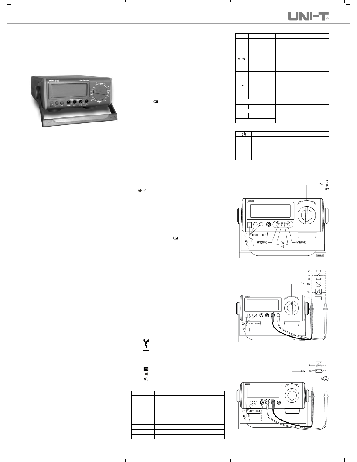
Operational Measurement Guide (see Diagram 1, 2,
3)
Diagram 1
Diagram 2
Diagram 3
Functions
Symbol Terminal Input
Explanation
V V
←→
COM DC Voltage Measurement
V V
←→
COM AC Voltage Measurement
Ω V
←→
COM Resistance Measurement
V
←→
COM Diode / Continuity Buzzer
Measurement
kHz V
←→
COM Frequency Measurement
A
mA μA ←→ COM
mA/μA DC Current Measurement
10A
←→
COM
ADCCurrent Measurement
A
mA μA ←→ COM
mA/μA AC Current Measurement
10A
←→
COM
A AC Current Measurement
F V←→ mA μA
Capacitance Measurement
(Use Multi-Purpose Socket)
V
←→
mA μA
Temperature Measurement
(Use Multi-Purpose Socket)
hFE V ←→mA μA Triode Enlargement Factor
(Use Multi-Purpose Socket)
Measurement
℃
Functional Buttons
Turn the power on and off Turn the display
backlight on and off(suitable for battery
supply, backlight turn on about 10 seconds
after auto shut down.)
Press Hold to enter and exit the hold mode
in any mode, the meter beeps.
LIGHT
HOLD
Page 2
hFE
Warning:
1. Selecting the correct terminal input and turns the
rotary switch to select the measuring function. If fails
to do that, the buzzer beep and the warning signal
ash on.
Range Alarm Alert On False Terminal Input
V Hz Ω 10A mAμA
mAμA ℃ hFE F 10A
10A mAμA
2.DC or AC Voltage Measurement
● To avoid harms to you or damages to the Meter
from electric shock, please do not attempt to measure
voltages higher than 1000 V although reading may
be obtained.
● Th e Me t e r ha s a n i n p u t im p e da n ce o f
10MΩ(exceptUT802/ACV input impedance of 2MΩ)
This loading effect can cause measurement errors in
high impedance circuits and so you need to take a
note on it.
3.DC or AC Current Measurement
● Before connect the Meter in serial with the tested
return circuit, closed
the return circuit current to avoid the dangerous of
sparking.
● Do not use over >10A current measurement.
Although the meter can work on below 20A current
tes ting but for the avoidi ng an y harms to you or
damages to the Meter.
4. Me asu ri n g Res ist an ce, Diod e s, Conti nu i ty or
Capacitance
● To maintain the measurement accuracy, discount
cir cu it power an d disc ha rg e all the high voltag e
capacitors during the measuring resistance.
● When measur in g high resi stanc e on 1M Ω or
ab ov e , it is n or m al to tak e seve ra l seco n ds to
obtain a stable reading . In order to obtain stable
readin g, choos e shorter test lead to ca rry ing out
measurement.
● The test le ads and the Meter insid e wire will
bring around 0.1Ω~0.2Ω o f err or to r es is tan ce
measurement when measuring low resistance. To
obtain accur ate re adings in low- res istance, short
–cir cui t the tes t leads be for ehand and record th e
reading obtained, call this reading as X. Then use
the equation: measured resistance value (Y) – (X) =
accurate readings of resistance.
● During measurement, Diodes is in a good silicon
junction drops between 500mV~800m V as the
normal value. The continuity measurement, the poles
between resistance is >100Ω. it is a short circuit, but
on the poles between resistance is ≤10Ω, it is a good
connection, buzzer is continually beep on, and the
reading value is nearly to the circuit resistance value,
Unit is Ω.
Accuracy Specications
Accuracy: ±(% reading + digits), guarantee for 1 year
Operating temperature: 18℃~28
℃
Environmental humidity: Less than 75%RH
1. DC Voltage
Range Resolution
UT801 UT802 UT801 UT802
200mV 0.1mV 0.01mV ±(0.1%+5)
2V 1mV 0.1mV
20V 10mV 1mV ±(0.5%+2) ±(0.1%+3)
200V 100mV 10mV
1000V 1V 0.1V ±(0.8%+3) ±(0.2%+5)
Input Impedance: is average on 10MΩ
Max im um Vol ta ge Input: 1000 V (Exc ep t 200m V,
250V)
2. AC Voltage
Range Resolution
UT801 UT802 UT801 UT802
2V 1mV 0.1mV ±(0.8%+3) ±(0.5%+20)
20V 10mV 1mV
200V 100mV 10mV ±(1.0%+4)
±(0.8%+40)
1000V 1V 0.1V
Input Impe dance : UT801 is aver age on 10MΩ ,
UT802 is about 2MΩ .
Maximum Voltage Input: 750Vrms
Frequency: 45Hz~400Hz
Display: True RMS
3. DC Current
Range Resolution
UT801 UT802 UT801 UT802
200μA 0.1μA 0.01μA
2mA 1μA 0.1μA
20mA 10μA 1μA ±(0.8%+2) ±(0.5%+20)
200mA 0.1mA 0.01mA
10A 10mA 1mA ±(2.0%+4) ±(1.5%+40)
* When ≥5A, Continuous measurement less than 10
seconds at an interval more than 15 minutes.
4. AC Current
Range Resolution
UT801 UT802 UT801 UT802
2mA 1μA 0.1μA
20mA 10μA 1μA ±(1.0%+3) ±(0.8%+40)
200mA 0.1mA 0.01mA
10A 10mA 1mA ±(2.5%+5) ±(2.0%+40)
Frequency: 45Hz~400Hz
* When ≥5A, Continuous measurement less than 10
seconds at an interval more than 15 minutes.
5. Resistance
Range Resolution
UT801 UT802 UT801 UT802
200Ω 0.1Ω 0.01Ω
2kΩ 1Ω 0.1Ω
20kΩ 10Ω 1Ω ±(0.8%+3) ±(0.5%+10)
200kΩ 100Ω 10Ω
2MΩ 1kΩ 100Ω
20MΩ 10kΩ ±(1.2%+5)
200MΩ 10kΩ ±(5%+40)
When >100MΩ resistance measurement as reference
purpose.
6. Capacitance
Range Resolution
UT801 UT802 UT801 UT802
20nF 10pF 1pF
2μF 1nF 100pF
200μF* 100nF 10nF
±(5%+5) ±5%+10)
*>40 μF capa ci ta nce m ea su remen t as referen ce
purpose.
7. Frequency
Range Resolution
UT801 UT802 UT801 UT802
2kHz 1Hz 0.1Hz
200kHz 100Hz 10Hz
Input Amplitude a:
(2kHz range) 50mV≤a≤30Vrms
(200kHz range)150mV≤a≤30Vrms
8. Temperature
R
ange Resolution
UT801 UT802 UT801 UT802
-40~-20℃ -(8%+5) -(8%+40)
>-20℃0℃ ±(1.2%+4) ±(1.2%+30)
>0~100℃ ±(1.2%+3) ±(1.2%+25)
>100~1000
℃
±(2.5%+2) ±(2.5%+20)
* Ther moc o u ple : I t is sui t a ble t o use K t y pe
the rm oc ou pl e. T hi s incl ud e poin t contact K type
thermocouple can only be used on less than 230
℃
temperature measurement.
9. Diode Test
Range Resolution Remarks
UT801 UT802
1mV 0.1mV
10. Continuity Test
Range Resolution Remarks
UT801 UT802
1Ω* 0.1Ω*
Whe n circ ui t disc on ne ct ed with resistance value
>100Ω, buzzer does not beep.
When circuit is in good connectio n with re sistance
value ≤10Ω, buzzer beeps continuously.
11. Transistor hFE
Range Resolution Remarks
UT801 UT802
1β* 0.1β*
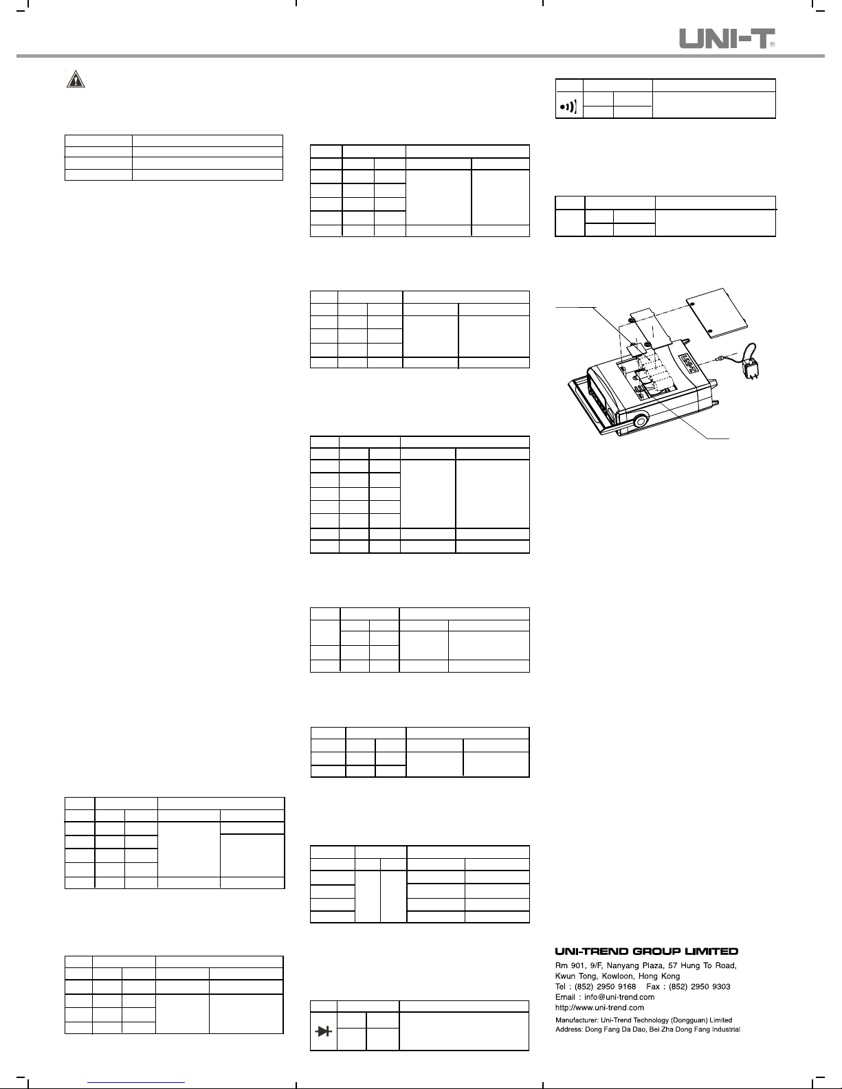
Replacing the battery(see Diagram 4)
Accuracy Tolerance:±(% Reading+Digits)
Accuracy Tolerance:±(% Reading+Digits)
Accuracy Tolerance:±(% Reading+Digits)
Accuracy Tolerance:±(% Reading+Digits)
Accuracy Tolerance:±(% Reading+Digits)
Ope n circui t voltag e is aro und 3
V, Si licon junct ion drops betw een
0.5~0.8V as the normal value.
O p e n c i r c u i t v o l t a g e is
approximate 3V
Ib 0 is ab ou t 10μ A, Vc e is
about 2.5V
Diagram 4
R14 1.5V*6
Fuse
Power
adapter
Specifications and ot her info rmat ion show n on this
ins tr uc tion ma nu al are subj ec t to chan ge w ithout
notice
UT801/802
Operating Manual
Accuracy Tolerance:±(% Reading+Digits)
1℃ 0.1
℃
Accuracy Tolerance:±(% Reading+Digits)
±(1.5%+5) ±(1.2%+10)
Accuracy Tolerance:±(% Reading+Digits)
±(4%+3) ±(4%+10)
P/N: 110401101618
Development District,Hu Men Town,Dong Guan City,
Guang Dong Province,China
 Loading...