

UNI-T UT60F, UT60G Operating Manual
Page
3
4
5
6
8
9
10
1 1
13
15
17
17
18
19
21
23
24
26
27
29
DC or AC Current Measurement
30
31
32
32
32
33
33
Measuring Resistance
Testing Diodes
Testing for Continuity
Capacitance Measurement
Frequency Measurement
Model UT60 G: Temperature
Measurement
Functional Button
Rotary Switch
Display Symbols
Measurement Ranges
Model UT60F/G: OPERATING MANUAL
1
Table of Contents
Title
Overview
Unpacking Inspection
Safety Information
Rules For Safe Operation
International Electrical Symbols
The multimeter Structure
Measurement Operation
C.
D.
E.
F.
G.
H.
I.
D. AC Current
General Specifications
Sleep Mode
Accuracy Specifications
A. DC Voltage
B. AC Voltage
C. DC Current
A. DC Voltage Measurement
B. AC Voltage Measurement
Page
34
34
34
I.
35
35
C. Replacing the Fuses
36
36
36
37
Resistance
Diode Test
Continuity Test
Capacitance
Frequency
J.
35
Temperature
Maintenance
Model UT60F/G: OPERATING MANUAL
2
Title
E.
F.
G.
H.
A. General Service
B. Replacing the Battery

Digital Multimeter Model UT60F/UT60G (hereafter
referred to as “the Meter”) are 3 3/4 digits with steady
operations, fashionable structure and highly reliable
measuring instrument. The Meter uses large scale of
integrated circuit with double integrated A/D converter
as its core and has full range overload protection.
The Meter can measure AC/DC Voltage, AC/DC Current,
Resistance, Capacitance, Temperature, Frequency,
Diodes, Continuity and etc. The Meter adopted advanced
“co-injection” technique in order to provide sufficient
insulation. In addition, the Display Backlight feature
enables user to work in a dim condition.
This Operating Manual covers information on safety and
cautions. Please read the relevant information carefully
and observe all the Warnings and Notes strictly.
Overview
Warning
To avoid electric shock or personal injury, read the
"Safety Information" and "Rules for Safe Operation"
carefully before using the Meter.
Model UT60F/G: OPERATING MANUAL
3
Unpacking Inspection
Open the package case and take out the Meter. Check
the following items carefully to see any missing or
damaged part:
In the event you find any missing or damage, please
contact your dealer immediately.
Point Contact Temperature Probe
(UT60G only)
5 RS-232C Interface Cable 1 piece
CD-ROM (Installation Guide &
Computer Interface Software)
1 piece
6
Model UT60F/G: OPERATING MANUAL
4
Item
1
2
3
4
Description
English Operating Manual
Test Lead
Test Clip
Qty
1 piece
1 pair
1 pair
1 piece

Safety Information
This Meter complies with the standards IEC61010: in
pollution degree 2, overvoltage category (CA T. III 1000V,
CAT. IV 600V) and double insulation.
CA T. III: Distribution level, fixed installation, with smaller
transient overvoltages than CAT. IV
CAT IV: Primary supply level, overhead lines, cable
systems etc.
Use the Meter only as specified in this operating manual,
otherwise the protection provided by the Meter may be
impaired.
In this manual, a Warning identifies conditions and actions
that pose hazards to the user, or may damage the Meter
or the equipment under test.
A Note identifies the information that user should pay
attention on.
International electrical symbols used on the Meter and
in this Operating Manual are explained on page 8.
Model UT60F/G: OPERATING MANUAL
5
Rules For Safe Operation (1)
Warning
To avoid possible electric shock or personal injury,
and to avoid possible damage to the Meter or to the
equipment under test, adhere to the following rules:
l Before using the Meter inspect the case. Do
not use the Meter if it is damaged or the case (or
part of the case) is removed. Look for cracks or
missing plastic. Pay attention to the insulation
around the connectors.
l Inspect the test leads for damaged insulation
or exposed metal. Check the test leads for
continuity. Replace damaged test leads with
identical model number or electrical specifications
before using the Meter.
l Do not apply more than the rated voltage, as
marked on the Meter, between the terminals or
between any terminal and grounding.
l The rotary switch should be placed in the right
position and no any changeover of range shall
be made during measurement is conducted to
prevent damage of the Meter.
l When the Meter working at an effective voltage
over 60V in DC or 30V rms in AC, special care
should be taken for there is danger of electric
shock.
l Use the proper terminals, function, and range
for your measurements.
l Do not use or store the Meter in an environment
of high temperature, humidity, explosive,
inflammable and strong magnetic field. The
performance of the Meter may deteriorate after
dampened.
l When using the test leads, keep your fingers
behind the finger guards.
l Disconnect circuit power and discharge all high voltage capacitors before testing resistance,
continuity, diodes, current or capacitance.
Model UT60F/G: OPERATING MANUAL
6

Rules For Safe Operation (2)
l Before measuring current, check the Meter’s
fuses and turn off power to the circuit before
connecting the Meter to the circuit.
l Replace the battery as soon as the battery
indicator appears. With a low battery , the Meter
might produce false readings that can lead to
electric shock and personal injury.
l Remove test leads, point contact temperature
probe and RS232C interface cable from the Meter
and turn the Meter power off before opening the
Meter case.
l When servicing the Meter, use only the same
model number or identical electrical specifications
replacement parts.
l The internal circuit of the Meter shall not be
altered at will to avoid damage of the Meter and
any accident.
l Soft cloth and mild detergent should be used
to clean the surface of the Meter when servicing.
No abrasive and solvent should be used to
prevent the surface of the Meter from corrosion,
damage and accident.
l The Meter is suitable for indoor use.
l Turn the Meter off when it is not in use and
take out the battery when not using for a long
time.
l Constantly check the battery as it may leak when
it has been using for some time, replace the
battery as soon as leaking appears. A leaking
battery will damage the Meter.
Model UT60F/G: OPERATING MANUAL
7
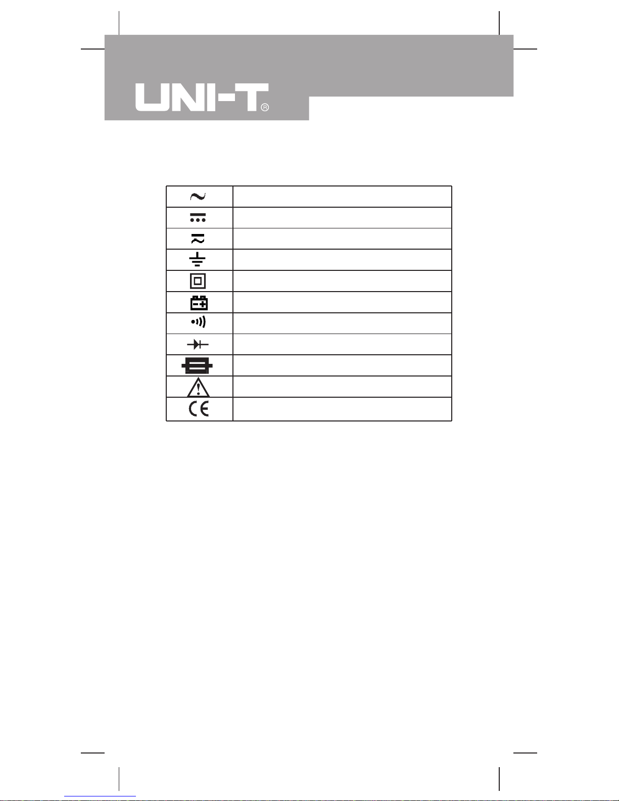
International Electrical Symbols
AC (Alternating Current).
DC (Direct Current).
AC or DC.
Grounding.
Double Insulated.
Deficiency of Built-In Battery.
Continuity Test.
Diode.
Fuse.
Warning. Refer to the Operating Manual.
Conforms to Standards of European Union.
Model UT60F/G: OPERATING MANUAL
8
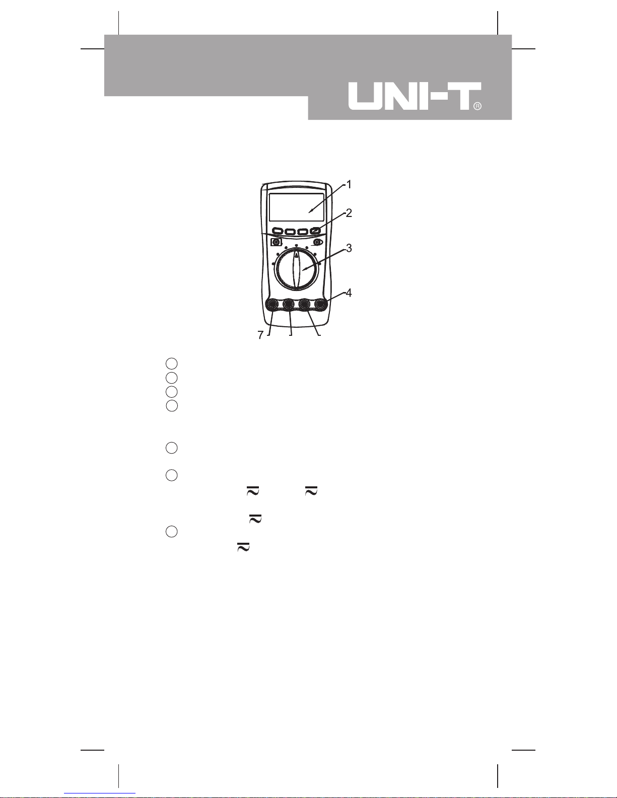
The multimeter Structure (see figure 1)
9
( figure 1)
1 LCD Display
2 Functional Buttons
3 Rotary Switch
4 HzVΩInput Terminal:
Input for voltage, frequency, resistance,diode,
capacitance and continuity measurements.
5 COM Input Terminal:
Return terminal for all measurements.
6 Model UT60F: µA mA Input Terminal;
Input for µA and mA measurement.
Model UT60G: mAoC Input Terminal
Input for mA and temperature measurement.
7 10A Input Terminal
Input for A measurement.
5
6
Model UT60F/G: OPERATING MANUAL
10
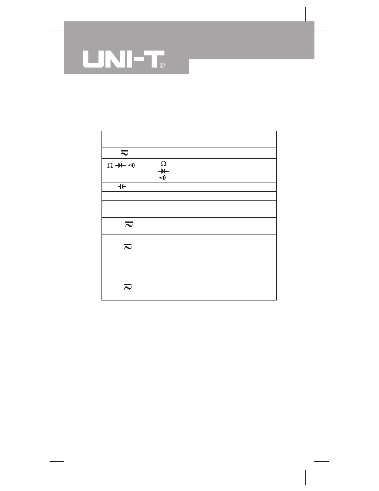
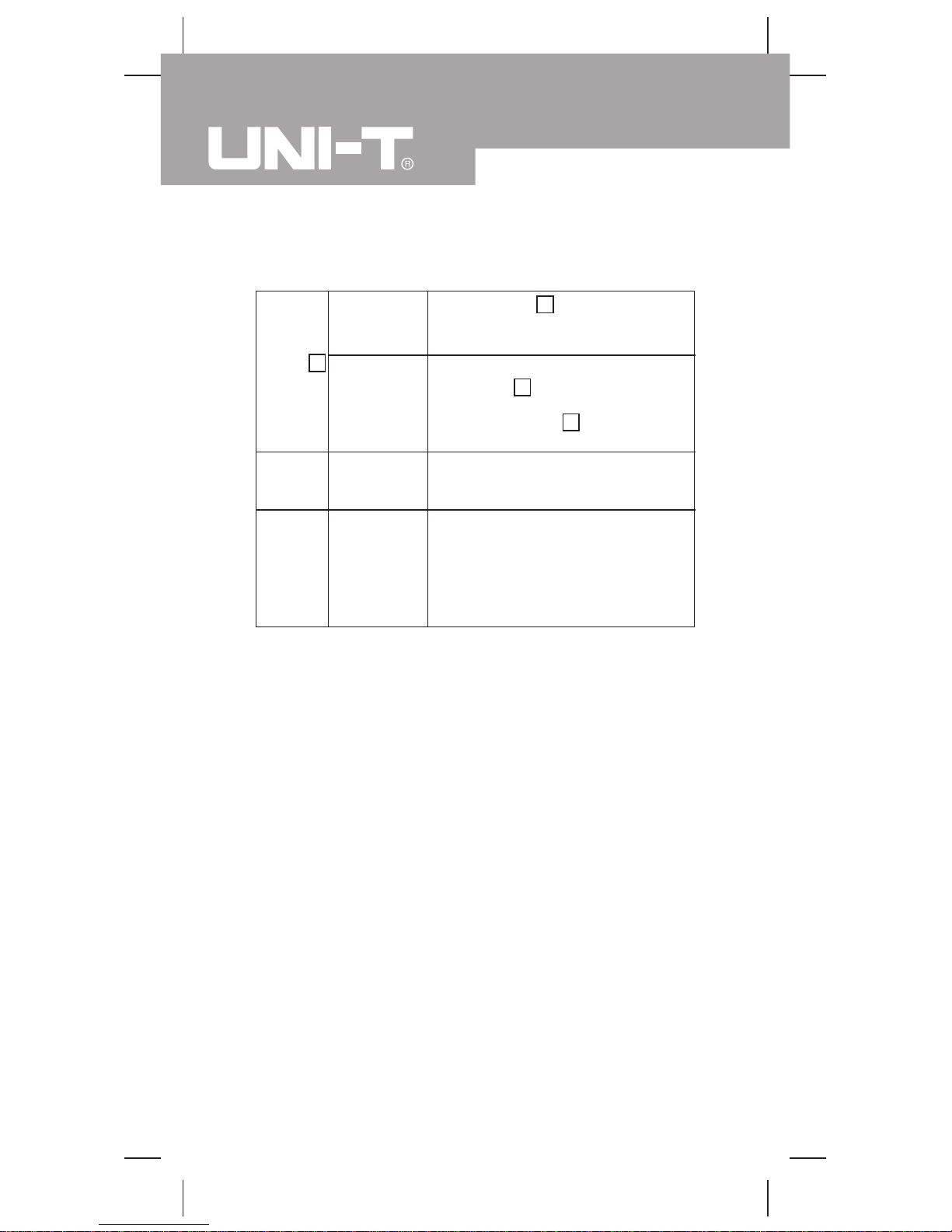
Rotary Switch
Below table indicated for information about the rotary
switch positions.
Rotary Switch
Position
Function
AC or DC voltage measurement
: Resistance measurement
: Diode test
: Continuity test
Capacitance measurement
Frequency measurement
Hz
Temperature measurement
(UT60G only)
o
C
AC or DC current measurement range
from 0.1µA to 4.000mA (UT60F only)
µA
Model UT60F: AC or DC current
measurement range from 0.01mA to
400.0mA
Model UT60G: AC or DC current
measurement range from 0.01mA to
600.0mA.
mA
AC or DC current measurement
range from 10mA to 10.00A
A
V
Model UT60F/G: OPERATING MANUAL
11
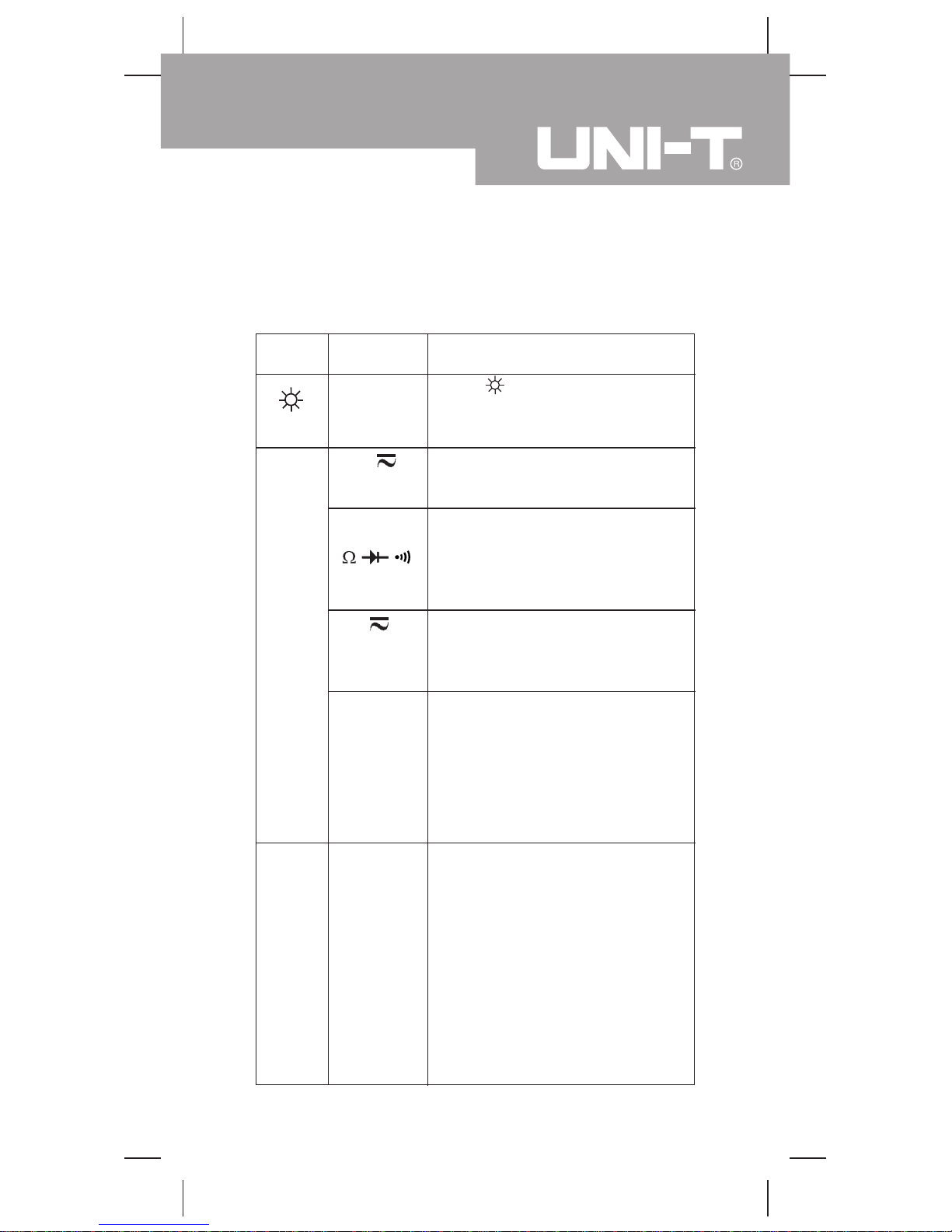
Functional Button(1)
Below table indicated for information about the functional
button operations.
Button
Measuring
Function
Operation Performed
Display
Backlight
Press once to turn the Display
Backlight on and it shall shut off
automatically in around 60 seconds
later.
V
Switches between AC and DC
Voltage; the Meter beeps. DC is
default.
(BLUE)
Switches between continuity and
diode and resistance
measurement;
The Meter beeps.
Resistance is default.
Switches between AC and DC
current range from 0.1µA to
4.000mA; the Meter beeps. DC
is default
(UT60F
ONLY)
µA
Model UT60F: Switches between
AC and DC current measurement
range from 0.01mA to 400.0mA;
the Meter beeps. DC is default.
Model UT60G: Switches between
AC and DC current measurement
range from 0.01mA to 600.0mA ;
the Meter beeps. DC is default.
mA
RANGE
Any rotary
Switch
Position
1.Press RANGE to enter the
manual ranging mode; the Meter
beeps.
Manually selecting a range
causes the Meter to exit the
Hold mode.
2.Press RANGE to step through
the ranges available for the
selected function; the Meter
beeps.
3.Press and hold RANGE for over
1 second to return to autoranging;
the Meter beeps.
Model UT60F/G: OPERATING MANUAL
12
Functional Button(2)
Any rotary
Switch
Position
Press HOLD H to enter and exit
the Hold mode in any mode, the
Meter beeps.
At OFF
position
l Press and hold
HOLD H button while turning
on the Meter to display full icons.
l Press HOLD H again to return
to normal display mode.
HOLDH
POWER
Any rotary
Switch
Position
Turn the Meter’s power on and off.
RS232C
Any rotary
switch
position
Turn on or off the serial port
interface without changing the
original setting. Although HOLD H
is on, outputted data displayed
on the computer is the current
measurement value.
Model UT60F/G: OPERATING MANUAL
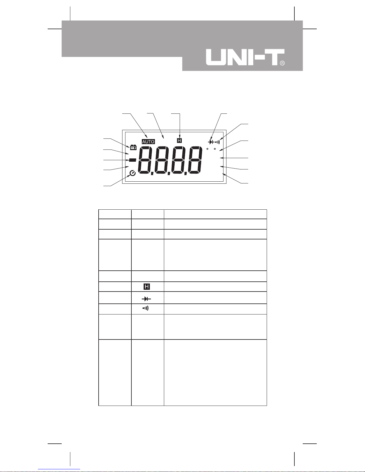
Display Symbols(1) (see figure 2)
13
Number Symbol Meaning
Indicator for DC voltage or current1 DC
Indicator for AC voltage or current2 AC
The Meter is in the auto range
mode in which the Meter autom
atically selects the range with the
best resolution.
AUTO
3
Data output is in progress
4 RS232C
Data hold is active
5
Test of diode
6
The continuity buzzer is on
7
The unit of temperature:
Centigrade temperature
Fahrenheit temperature
8
Farad. The unit of capacitance
nF: Nanofarad. 1x10
-9
or
0.000000001 farads.
µF:Microfarad.1x10
-6
or
0.000001 farads.
mF: Millifarad. 1x10⁻³ or
0.001 farads.
9
nF,µF,
mF
o
C
o
F
Model UT60F/G: OPERATING MANUAL
( figure 2)
n mF
µ
C F
1
2
14
15
16
3
4 5 6
7
8
9
10/11
12/13
DC
AC
mVA
Mk Hz
µ
Ω
RS232C
 Loading...