


LEA-5S
u-blox LEA-5S, NEO-5, LEA-5Q, LEA-5A, LEA-5T Hardware Manual
...
Abstract
This document describes the hardware features and specifications of
the cost effective and high-performance LEA-5, NEO-5 and TIM-5H
GPS modules featuring the u-blox 5 positioning engine.
These compact, easy to integrate stand-alone GPS receiver modules
combine exceptional GPS performance with highly flexible power,
design, and connectivity options. Their compact form factors and
SMT pads allow fully automated assembly with standard pick &
place and reflow soldering equipment for cost-efficient, highvolume production enabling short time-to-market.
locate, communicate, accelerate
www.u-blox.com
LEA-5, NEO-5, TIM-5H
u-blox 5 GPS Modules
Hardware Integration Manual

Document Information
Title
LEA-5, NEO-5, TIM-5H
Subtitle
u-blox 5 GPS Modules
Document type
Hardware Integration Manual
Document number
GPS.G5-MS5-09027-A2
Document status
Released
This document contains the final product specification.
Name
Type number
ROM/FLASH version
PCN reference
LEA-5H
LEA-5H-0-009
LEA-5H-0-008
LEA-5H-0-007
FW6.02
FW6.00
FW5.00
UBX-TN-09017
UBX-TN-09001-A
UBX-TN-08027
LEA-5S
LEA-5S-0-004
ROM5.00
UBX-TN-08023
LEA-5A
LEA-5A-0-003
ROM5.00
UBX-TN-08023
LEA-5Q
LEA-5Q-0-002
ROM5.00
UBX-TN-08023
LEA-5M
LEA-5M-0-002
ROM5.00
UBX-TN-08023
LEA-5T
LEA-5T-0-003
LEA-5T-0-002
LEA-5T-0-001
FW6.02
FW6.00
FW5.00
UBX-TN-09017
UBX-TN-09001-A
UBX-TN-08027
NEO-5Q
NEO-5Q-0-002
ROM5.00
N/A
NEO-5M
NEO-5M-0-001
ROM5.00
N/A
NEO-5G
NEO-5G-0-000
ROM5.00
N/A
NEO-5D
NEO-5D-0-001
ROM5.00
N/A
TIM-5H
TIM-5H-0-004
TIM-5H-0-003
FW6.02
FW6.00
UBX-TN-09017
UBX-TN-09001-A
This document and the use of any information contained therein, is subject to the acceptance of the u-blox terms and conditions. They
can be downloaded from www.u-blox.com.
u-blox makes no warranties based on the accuracy or completeness of the contents of this document and reserves the right to make
changes to specifications and product descriptions at any time without notice.
u-blox reserves all rights to this document and the information contained herein. Reproduction, use or disclosure to third parties without
express permission is strictly prohibited. Copyright © 2009, u-blox AG.
u-blox® is a registered trademark of u-blox Holding AG in the EU and other countries. ARM® is the registered trademark of ARM Limited in
the EU and other countries.
This document applies to the following products:
LEA-5, NEO-5, TIM-5H - Hardware Integration Manual
GPS.G5-MS5-09027-A2 Page 2 of 68
LEA-5, NEO-5, TIM-5H - Hardware Integration Manual
Preface
u-blox Technical Documentation
As part of our commitment to customer support, u-blox maintains an extensive volume of technical
documentation for our products. In addition to our product-specific technical data sheets, the following manuals
are available to assist u-blox customers in product design and development.
GPS Compendium: This document, also known as the GPS book, provides a wealth of information
regarding generic questions about GPS system functionalities and technology.
Receiver Description including Protocol Specification: Messages, configuration and functionalities of
the u-blox 5 software releases and receivers are explained in this document.
Hardware Integration Manual: This Manual provides hardware design instructions and information on
how to set up production and final product tests.
Application Note: document provides general design instructions and information that applies to all u-blox
GPS receivers. See Section Related documents for a list of Application Notes related to your GPS receiver.
How to use this Manual
The LEA-5, NEO-5, TIM-5H Hardware Integration Manual provides the necessary information to successfully
design in and configure these u-blox 5-based GPS/GALILEO receiver modules. For navigating this document
please note the following:
This manual has a modular structure. It is not necessary to read it from the beginning to the end. To help in
finding needed information, a brief section overview is provided below:
1. Hardware description: This chapter introduces the basics of function and architecture of the u-blox 5
modules.
2. Design-in: This chapter provides the Design-In information necessary for a successful design.
3. Handling and soldering: This chapter defines packaging, handling, shipment, storage and soldering.
4. Product testing: This chapter provides information about testing of OEM receivers in production.
5. Appendix: The Appendix includes guidelines on how to successfully migrate to u-blox 5 designs, and useful
information about the different antenna types available on the market and how to reduce interference in
your GPS design.
This manual has a modular structure. It is not necessary to read it from the beginning to the end.
The following symbols are used to highlight important information within the manual:
An index finger points out key information pertaining to module integration and performance.
A warning symbol indicates actions that could negatively impact or damage the module.
GPS.G5-MS5-09027-A2 Released Preface
Page 3 of 68

LEA-5, NEO-5, TIM-5H - Hardware Integration Manual
Questions
If you have any questions about u-blox 5 Hardware Integration, please:
Read this manual carefully.
Contact our information service on the homepage http://www.u-blox.com
Read the questions and answers on our FAQ database on the homepage http://www.u-blox.com
Technical Support
Worldwide Web
Our website (www.u-blox.com) is a rich pool of information. Product information, technical documents and
helpful FAQ can be accessed 24h a day.
By E-mail
If you have technical problems or cannot find the required information in the provided documents, contact the
nearest of the Technical Support offices by email. Use our service pool email addresses rather than any personal
email address of our staff. This makes sure that your request is processed as soon as possible. You will find the
contact details at the end of the document.
Helpful Information when Contacting Technical Support
When contacting Technical Support please have the following information ready:
Receiver type (e.g. LEA-5A) and firmware version (e.g. V6.00)
Receiver configuration
Clear description of your question or the problem together with a u-center logfile
A short description of the application
Your complete contact details
GPS.G5-MS5-09027-A2 Released Preface
Page 4 of 68

LEA-5, NEO-5, TIM-5H - Hardware Integration Manual
Contents
Preface ................................................................................................................................ 3
Contents .............................................................................................................................. 5
1 Hardware description .................................................................................................. 8
1.1 Overview .............................................................................................................................................. 8
1.2 Architecture .......................................................................................................................................... 8
1.3 Power management ............................................................................................................................. 9
1.3.1 Connecting power ........................................................................................................................ 9
1.3.2 Operating modes ........................................................................................................................ 10
1.3.3 V_ANT (LEA-5H/5S/5A, TIM-5H) .................................................................................................. 11
1.4 System functions ................................................................................................................................ 11
1.4.1 EXTINT - –xternal interrupt pin ..................................................................................................... 11
1.4.2 System monitoring ...................................................................................................................... 11
1.5 Interfaces ............................................................................................................................................ 11
1.5.1 UART ........................................................................................................................................... 11
1.5.2 USB (LEA-5, NEO-5) ..................................................................................................................... 12
1.5.3 DDC (LEA-5, NEO-5) .................................................................................................................... 13
1.5.4 SPI (planned with LEA-5Q and NEO-5Q/5G) ................................................................................. 17
1.6 I/O pins ............................................................................................................................................... 22
1.6.1 RESET_N (LEA-5, TIM-5H) ............................................................................................................ 22
1.6.2 EXTINT0 ...................................................................................................................................... 22
1.6.3 AADET_N (LEA-5, TIM-5H) ........................................................................................................... 22
1.6.4 Configuration pins (LEA-5S/5A/5Q/5M, NEO-5) ........................................................................... 22
2 Design-in ..................................................................................................................... 23
2.1 Design-in checklist .............................................................................................................................. 23
2.1.1 Layout design-in checklist ............................................................................................................ 23
2.1.2 Design considerations .................................................................................................................. 25
2.2 LEA-5 design ...................................................................................................................................... 26
2.2.1 LEA-5 passive antenna design ...................................................................................................... 26
2.2.2 Pin description for antenna designs (LEA-5H/5S/5A/5T) ............................................................... 27
2.2.3 Pin description for antenna designs (LEA-5Q/5M) ........................................................................ 28
2.3 NEO-5 design ..................................................................................................................................... 30
2.3.1 Passive antenna design (NEO-5) ................................................................................................... 30
GPS.G5-MS5-09027-A2 Released Contents
Page 5 of 68

LEA-5, NEO-5, TIM-5H - Hardware Integration Manual
2.4 TIM-5H design .................................................................................................................................... 31
2.5 Layout ................................................................................................................................................ 32
2.5.1 Footprint and paste mask ............................................................................................................ 32
2.5.2 Placement ................................................................................................................................... 34
2.5.3 Antenna connection and grounding plane design ....................................................................... 36
2.5.4 Antenna micro strip ..................................................................................................................... 37
2.6 Antenna and antenna supervisor ........................................................................................................ 38
2.6.1 Passive antenna ........................................................................................................................... 39
2.6.2 Active antenna (LEA-5H/5S/5A/5T, TIM-5H) ................................................................................. 39
2.6.3 Active antenna (LEA-5Q/5M, NEO-5) ........................................................................................... 40
2.6.4 Active antenna bias power (LEA-5H/5S/5A/5T, TIM-5H) ............................................................... 41
2.6.5 Active antenna supervisor (LEA-5H/5S/5A/5T, TIM-5H)................................................................. 42
2.7 EOS/ESD/EMI Precautions .................................................................................................................... 46
2.7.1 Abbreviations .............................................................................................................................. 46
2.7.2 Electrostatic discharge (ESD) ........................................................................................................ 46
2.7.3 ESD protection measures ............................................................................................................. 46
2.7.4 Electrical Overstress (EOS) ............................................................................................................ 47
2.7.5 EOS protection measures ............................................................................................................. 47
2.7.6 Electromagnetic interference (EMI) .............................................................................................. 47
2.7.7 GSM applications ........................................................................................................................ 48
2.7.8 Recommended parts ................................................................................................................... 50
3 Handling and soldering ............................................................................................. 51
3.1 Packaging, shipping, storage and moisture preconditioning ............................................................... 51
3.2 ESD handling precautions ................................................................................................................... 51
3.3 Soldering ............................................................................................................................................ 52
3.3.1 Soldering paste............................................................................................................................ 52
3.3.2 Reflow soldering ......................................................................................................................... 52
3.3.3 Optical inspection ........................................................................................................................ 53
3.3.4 Cleaning ...................................................................................................................................... 53
3.3.5 Repeated reflow soldering ........................................................................................................... 54
3.3.6 Wave soldering............................................................................................................................ 54
3.3.7 Hand soldering ............................................................................................................................ 54
3.3.8 Rework ........................................................................................................................................ 54
3.3.9 Conformal coating ...................................................................................................................... 54
3.3.10 Casting ........................................................................................................................................ 54
3.3.11 Grounding metal covers .............................................................................................................. 55
GPS.G5-MS5-09027-A2 Released Contents
Page 6 of 68

LEA-5, NEO-5, TIM-5H - Hardware Integration Manual
3.3.12 Use of ultrasonic processes .......................................................................................................... 55
4 Product testing ........................................................................................................... 56
4.1 u-blox in-series production test ........................................................................................................... 56
4.2 Test parameters for OEM manufacturer .............................................................................................. 56
4.3 System sensitivity test ......................................................................................................................... 57
4.3.1 Guidelines for sensitivity tests ...................................................................................................... 57
4.3.2 ―Go/No go‖ tests for integrated devices ........................................................................................ 57
Appendix .......................................................................................................................... 58
A Migration to u-blox-5 receivers ................................................................................. 58
A.1 Checklist for migration ....................................................................................................................... 58
A.2 Software migration ............................................................................................................................. 60
A.3 Hardware Migration ........................................................................................................................... 61
A.4 Migration from LEA-4 to LEA-5 ........................................................................................................... 61
A.5 Migration from NEO-4S to NEO-5Q/NEO-5M ...................................................................................... 64
A.6 Migration from TIM-4H / TIM-4P to TIM-5H ........................................................................................ 65
A.7 Typical Pin Assignment TIM modules .................................................................................................. 66
Related documents........................................................................................................... 67
Revision history ................................................................................................................ 67
Contact .............................................................................................................................. 68
GPS.G5-MS5-09027-A2 Released Contents
Page 7 of 68

LEA-5, NEO-5, TIM-5H - Hardware Integration Manual
RF Front-End
with
Integrated LNA
Baseband Processor
Power
Management
TCXO or
Crystal (optional)
RTC
FLASH EPROM
(optional)
Antenna
Supervision
& Supply
(optional)
Power Control
RF_IN
V_ANT
AADET_N
VCC_RF
VCC
V_BACKUP
G ND
VCC
_OUT
UART
EXTINT
RESET_N
USBV2.0
CFG_xxx
Digital
IF Filter
Backup
RAM
ROM Code
GPS/GALILEO
Engine
ARM7TDMI-S
®
SRAM
TIMEPULSE
SAW
Filter
RTC
VDDIO
DDC
SPI
LEA-5 Block Diagram
1 Hardware description
1.1 Overview
The LEA-5, NEO-5 and TIM-5H modules are a family of standalone GPS receivers featuring the high performance
u-blox 5 positioning engine. These compact, easy to integrate modules combine exceptional GPS performance
with highly flexible power, design, and connectivity options. Their compact form factors and SMT pads allow
fully automated assembly with standard pick & place and reflow-soldering equipment for cost-efficient, highvolume production enabling short time-to-market.
u-blox GPS modules are not designed for life saving or supporting devices or for aviation and should not be used
in products that could in any way negatively impact the security or health of the user or third parties or that
could cause damage to goods.
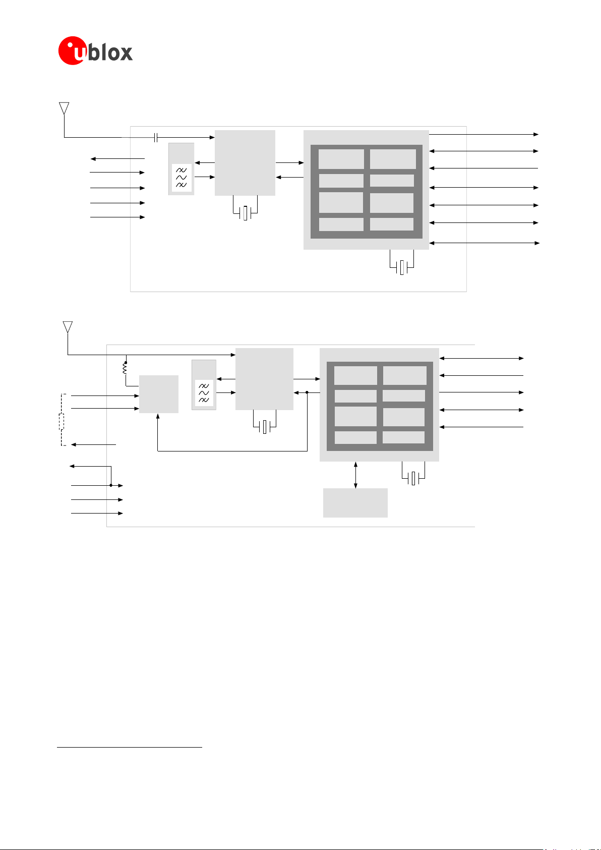
1.2 Architecture
LEA-5, NEO-5 and TIM-5H modules consist of two functional parts - –he RF and the Baseband sections. See
Figure 1 for a block diagram of the modules.
The RF Front-End includes the input matching elements, the integrated Low Noise Amplifier (LNA), the SAW
bandpass filter, the u-blox 5 RF-IC and the Crystal.
The Baseband section contains the u-blox 5 Baseband processor, the RTC crystal and additional elements such as
the optional FLASH Memory for enhanced programmability and flexibility.
GPS.G5-MS5-09027-A2 Released Hardware description
Page 8 of 68
LEA-5, NEO-5, TIM-5H - Hardware Integration Manual
RF Front-End
with
Integrated LNA
Baseband Processor
Power
Management
TCXO or Crystal
RTC
RF_IN
Digital
IF Filter
Backup
RAM
ROM Code
GPS
Engine
ARM7TDMI-S
®
SRAM
SAW
Filter
RTC
VCC_RF
VCC
V_BACKUP
GND
SPI (optional)
DDC
TIMEPULSE
EXTINT
UART
USB V2.0
CFG
V_RESET
NEO-5 Block Diagram
RF Front-End
with
Integrated LNA
Baseband Processor
Power
Management
TCXO
RTC
FLASH Memory
Antenna
Supervision
Power Control
RF_IN
V_ANT
AADET_N
VCC_RF
VCC
V_BACKUP
GND
VCC
_OUT
UART
EXTINT
RESET_N
SAFEBOOT
TIMEPULSE
Digital
IF Filter
Backup
RAM
ROM Code
GPS/GALILEO
Engine
ARM7TDMI-S
®
SRAM
SAW
Filter
RTC
TIM-5H Block Diagram
1
Figure 1: Block diagrams of LEA-5, NEO-5 and TIM-5H modules
1.3 Power management
1.3.1 Connecting power
u-blox 5 receiver modules have up to three power supply pins: VCC, V_BCKP and VDDUSB1.
1.3.1.1 VCC - –ain power
The main power supply is fed through the VCC pin. During operation, the current drawn by the u-blox 5 GPS
module can vary by some orders of magnitude, especially, if low-power operation modes are enabled. It is
important that the system power supply circuitry is able to support the peak power (see datasheet for
Not available with TIM-5H
GPS.G5-MS5-09027-A2 Released Hardware description
Page 9 of 68

LEA-5, NEO-5, TIM-5H - Hardware Integration Manual
VCC
V_BCKP
Voltage
Supervisor
Module Voltage Supply
RTC and Battery Backup RAM (BBR)
J1
specification) for a short time. In order to define a battery capacity for specific applications the sustained power
figure shall be used.
When switching from backup mode to normal operation u-blox 5 modules must charge the internal
capacitors in the core domain. This can result in certain situations result in a significant current draw. For
low power applications using Power Save and backup modes it is important that the power supply or
low ESR capacitors at the module input can deliver this current/charge.
1.3.1.2 V_BCKP - –ackup battery
In case of a power failure on pin VCC, the real-time clock and backup RAM are supplied through pin V_BCKP.
This enables the u-blox 5 receiver to recover from a power failure with either a Hotstart or a Warmstart
(depending on the duration of VCC outage) and to maintain the configuration settings. If no backup battery is
connected, the receiver performs a Coldstart at power up.
If no backup battery available connect the V_BCKP pin to GND (or VCC).
As long as VCC is supplied to the u-blox 5 receiver, the backup battery is disconnected from the RTC and the
backup RAM in order to avoid unnecessary battery drain (see Figure 2). Power to RTC and BBR is supplied from
VCC in this case.
Figure 2: Backup Battery and Voltage
1.3.1.3 VDD_USB - –SB interface power supply (LEA-5, NEO-5)
VDD_USB supplies the I/Os of the USB interface. If the USB interface is not used, the VDD_USB pin must be
connected to GND. For more information regarding the correct handling of VDD_USB see section 1.5.2.1
1.3.2 Operating modes
u-blox 5 modules with FW 6.00 have 2 continuous operating modes (Maximum Performance and Eco) and 1
intermittent operating mode (Power Save mode). Maximum Performance mode freely uses the acquisition
engine, resulting in the best possible TTFF, while Eco mode optimizes the use of the acquisition engine to deliver
lower current consumption. At medium to strong signals, there is almost no difference for acquisition and
tracking performance in these modes.
1.3.2.1 Maximum Performance mode
In Maximum Performance mode, u-blox 5 receivers use the acquisition engine at full performance to search for
all possible satellites until the Almanac is completely downloaded.
As a consequence, tracking current consumption level will be achieved when:
A valid GPS position is fixed
Almanac is entirely downloaded
Ephemeris for all satellites in view are valid
GPS.G5-MS5-09027-A2 Released Hardware description
Page 10 of 68

LEA-5, NEO-5, TIM-5H - Hardware Integration Manual
2
1.3.2.2 Eco mode
In Eco mode, u-blox 5 receivers use the acquisition engine to search for new satellites only when needed for
navigation:
In cold starts, u-blox 5 searches for enough satellites to navigate and optimizes use of the acquisition
engine to download their ephemeris.
In non-cold starts, u-blox 5 focuses on searching for visible satellites whose orbits are known from the
Almanac.
In Eco mode, the u-blox 5 acquisition engine limits use of its searching resources to minimize power
consumption. As a consequence the time to find some satellites at weakest signal level might be slightly
increased in comparison to the Maximum Performance mode.
u-blox 5 deactivates the acquisition engine as soon as a position is fixed and a sufficient number (at least 4) of
satellites are being tracked. The tracking engine continues to search and track new satellites without orbit
information.
1.3.2.3 Power Save mode (new with FW 6.00)
u-blox 5 modules include power saving options that allow reducing the average tracking current consumption by
periodically switching off parts of or the complete GPS receiver and waking it up at configurable intervals from
one second to one week. This can be done by using a hardware interrupt or by sending a serial command. The
firmware also offers the option to reduce the peak and acquisition current independently of the power down
option.
1.3.3 V_ANT (LEA-5H/5S/5A, TIM-5H)
TIM-5H and LEA-5 modules supporting active antenna supply and supervision use the pin V_ANT to supply the
active antenna. Use a 10R resistor in front of V_ANT2. See chapter 2.6.
1.4 System functions
1.4.1 EXTINT - –xternal interrupt pin
EXTINT0 is an external interrupt pin used for the time mark function on LEA-5T. With FW 6.0, it can be used for
wake-up functions in low-power modes.
1.4.2 System monitoring
The u-blox-5 receiver modules provide system monitoring functions that allow the operation of the embedded
processor and associated peripherals to be supervised. These System Monitoring functions are output as part of
the UBX protocol, class ―MON‖.
Please refer to the u-blox 5 Receiver Description including Protocol Specification [2]. For more information on
UBX messages, serial interfaces for design analysis and individual system monitoring functions.
1.5 Interfaces
1.5.1 UART
u-blox 5 modules include up to 2 Universal Asynchronous Receiver Transmitter (UART) serial interfaces. UART 1
(RxD1/TxD1) is the default. It supports data rates from 4.8 to 230.4 kBit/s. The signal output levels are 0 V to
Only applies to modules supporting active antenna supply and supervision.
GPS.G5-MS5-09027-A2 Released Hardware description
Page 11 of 68

LEA-5, NEO-5, TIM-5H - Hardware Integration Manual
Module
VDD_USB
LDO
VDD_USB
R4
USB_DP
USB_DM
R5
C24 C23
D2
VBUS
DP
DM
GND
USB Device Connector
U1
EN R11
EN
Name
Component
Function
Comments
U1
LDO
Regulates VBUS (4.4 …5.25 V)
down to a voltage of 3.3 V).
Almost no current requirement (~1 mA) if the GPS receiver is operated as a USB
self-powered device, but if bus-powered LDO (U1) must be able to deliver the
maximum current of ~150 mA. A low-cost DC/DC converter such as LTC3410
from Linear Technology may be used as an alternative.
C23,
C24
Capacitors
Required according to the specification of LDO U1
D2
Protection
diodes
Protect circuit from overvoltage
/ ESD when connecting.
Use low capacitance ESD protection such as ST Microelectronics USBLC6-2.
R4, R5
Serial
termination
resistors
Establish a full-speed driver
impedance of 28…44 Ohms
A value of 27 Ohms is recommended.
R11
Resistor
10k R is recommended for USB self-powered setup. For bus-powered setup
R11 can be ignored.
VCC (or VDDIO where available). An interface based on RS232 standard levels (+/- 12 V) can be realized using
level shifters such as Maxim MAX3232.
The RxD1 has fixed input voltage thresholds, which do not depend on VCC (see module data sheet).
Leave open if unused.
Hardware handshake signals and synchronous operation are not supported.
For the default settings see the module data sheet.
1.5.2 USB (LEA-5, NEO-5)
The u-blox 5 Universal Serial Bus (USB) interface supports the full-speed data rate of 12 Mbit/s.
1.5.2.1 USB external components
The USB interface requires some external components in order to implement the physical characteristics required
by the USB 2.0 specification. These external components are shown in Figure 3 and listed in Table 1.
In order to comply with USB specifications, VBUS must be connected through a LDO (U1) to pin VDD_USB of
the module.
If the USB device is self-powered it is possible that the power supply (VCC) is shut down and the Baseband-IC
core is not powered. Since VBUS is still available, it still would be signaled to the USB host that the device is
present and ready to communicate. This is not desired and thus the LDO (U1) should be disabled using the
enable signal (EN) of the VCC-LDO or the output of a voltage supervisor. Depending on the characteristics of the
LDO (U1) it is recommended to add a pull-down resistor (R11) at its output to ensure VDD_USB is not floating if
LDO (U1) is disabled or the USB cable is not connected i.e. VBUS is not supplied.
If the device is bus-powered, LDO (U1) does not need an enable control.
Figure 3: USB Interface
Table 1: Summary of USB external components
GPS.G5-MS5-09027-A2 Released Hardware description
Page 12 of 68

LEA-5, NEO-5, TIM-5H - Hardware Integration Manual
DDC Device A DDC Device B
V
DD
SDA
SCL
GND
RpRp
SDA in
SDA out
SCL in
SDA out
SDA in
SDA out
SCL in
SDA out
1.5.3 DDC (LEA-5, NEO-5)
An I2C compatible Display Data Channel (DDC) interface is available with LEA-5 and NEO-5 modules for serial
communication. For more information about DDC implementation refer to the u-blox 5 Receiver Description
including Protocol Specification [2].
u-blox 5 GPS receivers normally run in the slave mode. Master Mode is only supported when external
EEPROM is used to store configuration. No other nodes are connected to the bus. In this case, the
receiver attempts to establish presence of such a non-volatile memory component by writing and
reading from a specific location.
Two wires, serial data (SDA) and serial clock (SCL), carry information between the devices connected to the bus.
These lines are connected to all devices on the DDC. SCL is used to synchronize data transfers and SDA is the
data line. Both SCL and SDA lines are "o“en drain" ”rivers. This means that DDC devices can only drive them
low or leave them open. The pull-up resistor (Rp) pulls the line up to VDD if no DDC device is pulling it down to
GND. If the pull-up resistors are missing, the SCL and SDA lines –are undefined and the DDC bus will not work.
For most DDC systems the low and high input voltage level thresholds of SDA and SCL depend on VDD. See
receiver datasheet for the applicable voltage levels.
Figure 4: A simple DDC connection
The signal shape and the maximum rate in which data can be transferred over SDA and SCL is limited by the
values of Rp and the wire and I/O capacitance (Cp). Long wires and a large number of devices on the bus
increase Cp, therefore DDC connections should always be as short as possible. The resistance of the pull-up
resistors and the capacitance of the wires should be carefully chosen.
Figure 5: DDC block diagram
GPS.G5-MS5-09027-A2 Released Hardware description
Page 13 of 68

LEA-5, NEO-5, TIM-5H - Hardware Integration Manual
Transmit
Receive
Master: sends the clock and addresses slaves
Sends data to slave
Receives data from slave
Slave: receives the clock and address
Sends data to master
Receives data from master
1.5.3.1 Addresses, roles and modes
Each device connected to a DDC is identified by a unique 7-bit address (e.g. whether it‖s a microcontroller,
EEPROM or D/A Converter, etc) and can operate as either a transmitter or receiver, depending on the function of
the device. The default DDC address for u-blox GPS receivers is set to 0x42. Setting the mode field in the CFGPRT message for DDC accordingly can change this address.
The first byte sent is comprised of the address field and R/W bit. Hence the byte seen on the bus 0x42 is
shifted by 1 to the left plus R/W bit thus being 0x84 or 0x85 if analyzed by scope or protocol analyzer.
In addition to transmitters and receivers, devices can also be considered as masters or slaves when performing
data transfers. A master is the device which initiates a data transfer on the bus and generates the clock signals to
permit that transfer. At that time, any device addressed is considered a slave. The DDC-bus is a multi-master bus,
i.e. multiple devices are capable of controlling the bus. Such architecture is not permanent and depends on the
direction of data transfer at any given point in time. A master device not only allocates the time slots when
slaves can respond but also enables and synchronizes designated slaves to physically access the bus by driving
the clock. Although multiple nodes can assume the role of a master, only one at any time is permitted to do so.
Thus, when one node acts as master, all other nodes act as slaves. Table 2 shows the possible roles and modes
for devices connected to a DDC bus.
Table 2: Possible roles and modes of devices connected to DDC bus
u-blox 5 GPS receivers normally run in the slave mode. There is an exception when an external EEPROM is
attached. In that case, the receiver attempts to establish presence of such a non-volatile memory component by
writing and reading from a specific location. If EEPROM is present (assumed to be located at a fixed address
0xA0), the receiver assumes the role of a master on the bus and never changes role to slave until the following
start-up (subject to EEPROM presence). This process takes place only once at the start-up, i.e. the receiver‖s role
cannot be changed during the normal operation afterward. This model is an exception and should not be
implemented if there are other participants on the bus contending for the bus control (µC / CPU, etc.).
Since the physical layer lacks a handshake mechanism to indicate the data availability, a layer has been inserted
between the physical layer and the UBX and NMEA layer. The DDC implements a simple streaming interface that
allows for constant data polling, discarding the segments of the data stream that do not belong to a valid UBX
or NMEA message. Thus the u-blox GPS receiver returns 0xFf If no data is available. If the polling process is
suspended for an extended period of time of 1.5 sec, the receiver temporarily stops writing data to the output
buffer to prevent overflowing.
As a slave on the bus, the u-blox 5 GPS receiver cannot initiate the data transfers. The master node has the
exclusive right and responsibility to generate the data clock, therefore the slave nodes need not be configured to
use the same baud rate. For the purpose of simplification, if not specified differently, SLAVE denotes the u-blox 5
GPS receiver while MASTER denotes the external device (CPU, μC) controlling the DDC bus by driving the SCL
line.
u-blox GPS receivers support standard mode I2C-bus specification with 7-bit addressing and a data
transfer rate up to 100 kbit/s.
1.5.3.2 Communicating to a slave with the GPS receiver as master
Pins SDA2 and SCL2 have internal pull-ups. If capacitive bus load is large, additional external pull-ups may be
needed in order to reduce the pull-up resistance.
Table 3 lists the maximum total pull-up resistor values for the DDC interface. The pull-up resistors integrated in
the pads of the baseband-IC can simply be ignored for high capacitive loads. However, for small loads, e.g. if just
connecting to an external EEPROM, these built-in pull-ups are sufficient.
GPS.G5-MS5-09027-A2 Released Hardware description
Page 14 of 68

LEA-5, NEO-5, TIM-5H - Hardware Integration Manual
Load Capacitance
Pull-Up Resistor Value R20, R21
50 pF
18 k
100 pF
9 k
250 pF
4 k
u-blox 5 Module EEPROM
SDA2
SCL2
SDA
SCL
VDD
VDD_IO
VDD
R20
VDD_IO
VDD_IO
R21
A0
A1
A2
WP
Table 3: Pull-up resistor values for DDC interface
Serial I2C memory can be connected to the DDC interface. It will automatically be recognized by firmware. The
memory address must be set to 0b1010000 and the size fixed to 4 kB.
Figure 6: Connecting external serial I2C memory used by the GPS receiver (see data sheet for exact pin orientation)
Note that the case shown on Figure 6 is different than the case when EEPROM is present but used by external
host / CPU as indicated on Figure 7. This is allowed but precaution is required to ensure that the GPS receiver
does not detect the EEPROM device, which would effectively configure the GPS receiver to be MASTER on the
bus causing collision with the external host.
To ensure that the EEPROM device (connected to the bus and used by the host) is not detected by the GPS
receiver it is important to set the EEPROM‖s address to a value different than 0xA0. This way EEPROM remains
free to be used for other purposes and the GPS receiver will assume the SLAVE mode.
Ensure that at the start up the host allows enough time for the receiver to communicate over the bus to
establish presence of the EEPROM. It is only when this interrogation is complete that the host can
exercise full control over the bus (MASTER mode).
Also note that the FLASH based modules do not attempt to store any information in the external
EEPROM and as such do not attempt to communicate to the external EEPROM. The ROM based
receivers always interrogate external EEPROM at the start-up. The interrogation process is guaranteed to
complete within 250ms upon start up. This is the time the external host has to give to the ROM based
GPS receiver to complete the EEPROM interrogation.
Although the FLASH based modules do not attempt to detect the EEPROM at the start up, an attempt to
communicate to the GPS receiver via DDC before 250msec expires is not advised because the GPS
receiver is unable to respond due to other start up activities.
GPS.G5-MS5-09027-A2 Released Hardware description
Page 15 of 68

LEA-5, NEO-5, TIM-5H - Hardware Integration Manual
u-blox 5 Module EEPROM
SDA2
SCL2
SDA
SCL
VDD
VDD_IO
VDD
R20
VDD_IO
VDD_IO
R21
External CPU / Host
SDA SCL
VDD
A0
A1
A2
WP
}
000
Figure 7: Connecting external serial I2C memory used by external host (see data sheet for exact pin orientation)
1.5.3.3 DDC troubleshooting
Consider the following questions when implementing DDC in designs:
Is there a stable supply voltage Vcc? Often, external I
provided with Vcc.
Are appropriate termination resistances attached between SDA, SCL and Vcc? The voltage level on SDA and
SCL must be Vcc as long as the bus is idle and drop near GND if shorted to GND. [Note: Very few I2C
masters exist which drive SCL high and low, i.e. the SCL line is not open-drain. In this case, a termination
resistor is not needed and SCL cannot be pulled low. These masters will not work together with other
masters (as they have no multi-master support) and may not be used with devices which stretch SCL during
transfers.]
Are SDA and SCL mixed up? This may accidentally happen e.g. when connecting I
connectors.
Do all I
Do all I
If more than one I2C master is connected to the bus: do all masters provide multi-master support?
2
C devices support the I2C supply voltage used on the bus?
2
C devices support the maximum SCL clock rate used on the bus?
Are the high and low level voltages on SDA and SCL correct during I2C transfers? The I
the low level threshold with 0.3 Vcc, the high level threshold with 0.7 Vcc. Modifying the termination
resistance Rp, the serial resistors Rs or lowering the SCL clock rate could help here.
Are there spikes or noise on SDA, SCL or even Vcc? They may result from interferences from other
components or because the capacitances Cp and/or Cc are too high. The effects can often be reduced by
using shorter interconnections.
2
C devices (like I2C masters or monitors) must be
2
C buses with cables or
2
C standard defines
GPS.G5-MS5-09027-A2 Released Hardware description
Page 16 of 68

LEA-5, NEO-5, TIM-5H - Hardware Integration Manual
SPI Slave
MISO
MOSI
SCK
SCS
For more information about DDC implementation refer to the u-blox 5 Receiver Description including
Protocol Specification [2].
1.5.4 SPI (planned with LEA-5Q and NEO-5Q/5G)
A Serial Peripheral Interface (SPI) will be available with selected u-blox 5 modules for serial communication. This
is a synchronous serial data link standard that operates in full duplex mode. SPI is primarily used to enable a
microcontroller unit ( C) to communicate with peripheral devices. Peripheral devices can be as simple as an
ordinary transistor-transistor logic (TTL) shift register or as complex as a complete subsystem.
1.5.4.1 SPI basics
Devices communicate in master/slave mode where the master device provides the clock signal (SCK) and
determines the state of the chip select (SCS/SS_N) lines, i.e. it activates the slave it wants t o communicate with.
The slave device receives the clock and chip select from the master. Multiple slave devices are allowed with
individual slave select (chip select) lines. This means that there is one master, while the number of slaves is only
limited by the number of chip selects. In addition to reliability and relatively high speed (with respect to the
conventional UART), the SPI interface is easy to use and requires no special handling or complex communication
stack implementation in the software.
The standard configuration for a slave device (see Figure 8) uses two control and two data lines. These are
identified as follows:
SCS — Slave Chip Select (control: output from master, usually active low)
SCK — Serial Clock (control: output from master)
MOSI — Master Output, Slave Input (data: output from master)
MISO — Master Input, Slave Output (data: output from slave)
Alternative naming conventions are also widely used. Confirm the pin/signal naming with specific
components used.
Figure 8: SPI slave
SPI always follows the basic principle of a shift register. During an SPI transfer, command codes and data values
are simultaneously transmitted (shifted out serially) and received (shifted in serially). The data is entered into a
shift register and then internally available for parallel processing. The length of the shift registers is not fixed, but
can vary from device to device. Normally the shift registers are 8Bit or integral multiples thereof. However, they
can also have an odd number of bits. For example two cascaded 9Bit EEPROMs can store 18Bit data.
When an SPI transfer occurs, an 8-bit character is shifted out one data pin while a different 8-bit character is
simultaneously shifted in a second data pin. Another way to view this transfer is that an 8-bit shift register in the
master and another 8-bit shift register in the slave are connected as a circular 16-bit shift register. When a
transfer occurs, this distributed shift register is shifted eight bit positions; thus, the characters in the master and
slave are effectively exchanged.
The serial clock (SCK) line synchronizes shifting and sampling of the information on the two serial data lines
(MOSI and MISO). The chip select (SCS/SS_N) line allows individual selection of a slave SPI device. If an SPI slave
GPS.G5-MS5-09027-A2 Released Hardware description
Page 17 of 68

LEA-5, NEO-5, TIM-5H - Hardware Integration Manual
SPI Master
SPI Slave
0
Chip Select
MOSI
SCK
Data Input
MISO
SPI Slave
1
SPI Slave
2
SCS
0
SCS
1
SCS
2
Clock
Data Output
MOSI
MOSI
MOSI
SS_N
SS_N
SS_N
SCK
SCK
SCK
MISO
MISO
MISO
device is not selected (i.e. its chip select is not activated), its data output enters a high-impedance state (hi-Z) and
does not interfere with SPI bus activities.
The data output MISO functions as the data return signal from the slave to the master.
Figure 9 shows a typical block diagram for an SPI master with several slaves. Here, the SCK and MOSI data lines
are shared by all of the slaves. Also the MISO data lines are linked together and led back to the master. Only the
chip selects are separately brought to each SPI device.
Figure 9: Master with independent slaves
SPI allows multiple microcontrollers to be linked together. These can be configured according to single or
multiple master protocols. In the first variant the microcontroller(s) designated as slave(s) behave like a normal
peripheral device. The second variant allows for several masters and allows each microprocessor the possibility to
take the role of master and to address another microprocessor. In this case one microcontroller must
permanently provide the clock signal.
There are two SPI system errors. The first occurs if several SPI devices want to become master at the same time.
The other is a collision error that occurs for example when SPI devices work with different polarities.
Systems involving multiple microcontrollers are beyond the scope of this document.
Cascading slave peripherals is not supported.
Four I/O pin signals are associated with SPI transfers: the SCK, the MISO data line, the MOSI data line, and the
active low SCS/SS_N pin. In the unselected state the MISO lines are hi-Z and therefore inactive. The master
GPS.G5-MS5-09027-A2 Released Hardware description
Page 18 of 68

LEA-5, NEO-5, TIM-5H - Hardware Integration Manual
u-blox GPS Receiver EEPROM
SCS1_N
MISO
CE_N
SO
VDD
WP_N
SIMOSI
SCK SCK
VDD
decides with which peripheral device it wants to communicate. The clock line SCK provides synchronization for
data communication and is brought to the device whether or not it is selected.
The majority of SPI devices provide all four of these lines. Sometimes MOSI and MISO are multiplexed, or else
one is missing. A peripheral device, which must not or cannot be configured, requires no input line but only a
data output. As soon as it gets selected it starts sending data. In some ADCs therefore the MOSI line is missing .
Some devices have no data output (e.g. LCD controllers which can be configured, but cannot send data or status
messages).
The following rules should answer the most common questions concerning these signals:
SCK: The SCK pin is an output when the SPI is configured as a master and an input when the SPI is
configured as a slave. When the SPI is configured as a master, the SCK signal is derived from the internal bus
clock. When the master initiates a transfer, eight clock cycles are automatically generated on the SCK pin.
When the SPI is configured as a slave, the SCK pin is an input, and the clock signal from the master
synchronizes the data transfer between the master and slave devices. Slave devices ignore the SCK signal
unless the slave select pin is active low. In both the master and slave SPI devices, data is shifted on one edge
of the SCK signal and is sampled on the opposite edge where data is stable. Edge polarity is determined by
the SPI transfer protocol.
MISO/MOSI: The MISO and MOSI data pins are used for transmitting and receiving serial data. When the
SPI is configured as a master, MISO is the master data input line, and MOSI is the master data output line.
When the SPI is configured as a slave, these pins reverse roles.
SCS/SS_N: In master mode, the SCS output(s) select external slaves (e.g. SCS1_N, SCS2_N). In slave mode,
SS_N is the slave select input. The chip select pin behaves differently on master and slave devices. On a slave
device, this pin is used to enable the SPI slave for a transfer. If the SS_N pin of a slave is inactive (high), the
device ignores SCK clocks and keeps the MISO output pin in the high-impedance state. On a master device,
the SCS pin can serve as a general-purpose output not affecting the SPI.
1.5.4.2 Connecting serial memory to u-blox 5 modules
Serial SPI memory can be connected to the SPI interface. It will automatically be recognized by firmware when
connected to SCS1_N.
Figure 10 shows how external memory can be connected. Note that an external voltage is required to power the
EEPROM (VDD_IO on the receiver is an input).
Figure 10: Connecting external Serial SPI Memory to u-blox GPS receivers
External memory on the SPI interface is only supported by FW 6.00 and above. Only 128 kByte
memory size is supported.
1.5.4.3 Connecting u-blox 5 modules to an SPI master
Figure 11 shows how to connect a u-blox GPS receiver to a host/master. The signal on the pins must meet the
conditions specified in the Data Sheet.
GPS.G5-MS5-09027-A2 Released Hardware description
Page 19 of 68

LEA-5, NEO-5, TIM-5H - Hardware Integration Manual
u-blox GPS Receiver SPI Master
SSN_N
MISO
SCS_N
MI
VDD
MOMOSI
SCK SCK
VDD
Figure 11: Connecting to SPI Master
1.5.4.4 SPI and u-blox 5 configuration pins
With some u-blox 5 modules the SPI MOSI, MISO and SCK pins have a shared configuration function at start up.
To secure correct receiver operation make sure that the SS_N pin is high at start up. Afterwards the SPI function
will not affect the configuration pins.
GPS.G5-MS5-09027-A2 Released Hardware description
Page 20 of 68

LEA-5, NEO-5, TIM-5H - Hardware Integration Manual
SPI Slave
X
MOSI
X
u-blox 5
GPS Receiver
(SPI Slave1)
VDD_IO
SS_N
MOSI
(CFG_COM0)
MISO
(CFG_COM1)
SCK
(CFG_GPS0)
GND
Microprocessor
(SPI Master)
SPI
Chip
Select
DATA_OUT_SPI
SPI_Clock
DATA_IN_SPI
A
A
A
Y
Y
Y
OE
OE
OE
CSXN
CS2N
CS1N
Chip_Select
X
SPI Slave
2
Chip_Select
2
SCK
X
SCK
2
MOSI
2
MISO
X
MISO
2
U
1
U
2
U
3
Component
Description
Model
Supplier
U1 – U3
Buffer
NC7SZ125
Fairchild
1.5.4.5 Pin configuration with u-blox 5 module as one of several slaves
Figure 12: Diagram of SPI Pin Configuration
Figure 13: Recommended components for SPI pin configuration
Use same power voltage to supply U1 – U3 and VDD_IO.
GPS.G5-MS5-09027-A2 Released Hardware description
Page 21 of 68
 Loading...