


UBB Quick Start Guide
System Requirements
One of the following:
UniFi Cloud Key (1.0.5 or newer) or UniFi Dream Machine (1.0.1 or newer)
Linux, Mac OS X, or Microsoft Windows 7/8/10
Java Runtime Environment 1.6 (1.8 or newer recommended)
UniFi Controller software v5.12.x (or newer), available at: ui.com/download/unifi
UniFi Network App (iOS or Android™) or Web Browser (Google Chrome preferred)
Installation Requirements
Pole-mounting: 8 mm socket wrench or screwdriver
Wall-mounting: wall fastener (not included)
The device needs to have clear line of sight to the sky for proper GPS operation.
Shielded Category 5 (or above) cabling with drain wire should be used for all wired
Ethernet connections and should be grounded through the AC ground of the PoE.
We recommend that you protect your networks from harmful outdoor environments and
destructive ESD events with industrial-grade, shielded Ethernet cable from Ubiquiti. For
more details, visit
ui.com/toughcable
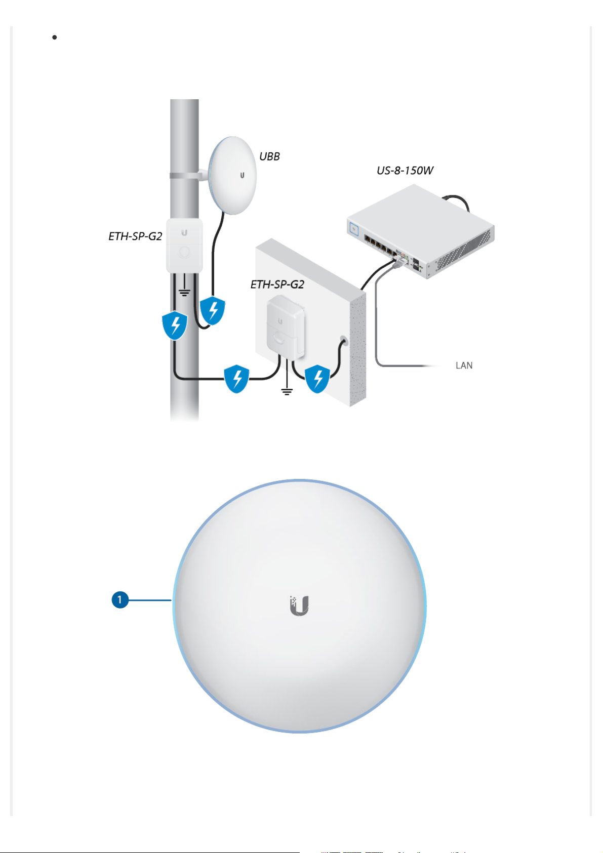
Surge protection should be used for all outdoor installations. We recommend that you use
two Ethernet Surge Protectors, model ETH-SP-G2, one near the device and the other at the
entry point to the building. The ETH-SP-G2 will absorb power surges and safely discharge
them into the ground.
Hardware Overview
System LED
Flashing White Initializing.
White Factory defaults, waiting for integration.
Device is busy; do not touch or unplug it. This usually
Alternating White/Blue
indicates that a process such as a firmware upgrade is
taking place.
Blue
Flashing
Red with Circulating Blue LED
Successfully integrated into a network and working
properly.
This is used to locate a device.
When you click Locate in the UniFi Network Controller
software, the LED will flash blue. The software will also
display the location of the device on the map.
The 60 GHz link cannot be established or has dropped
due to bad weather. If the UBB fails over to 5 GHz, the
LED will remain red. When the 60 GHz link is reestablished, the LED will turn blue or the custom color
you selected in the UniFi Network Controller.
Note: If the other bridge device is within range
and the UBB LED is red, we recommend
moving the UBB device up or down to enhance
the signal strength.
In the Manage Device section of the UniFi Network
Controller, you can enable the Alignment Tool. When the
UBB devices are properly aligned, the LED will turn green.

Green
Note: If the other bridge device is within range
and the UBB LED is green and red, we
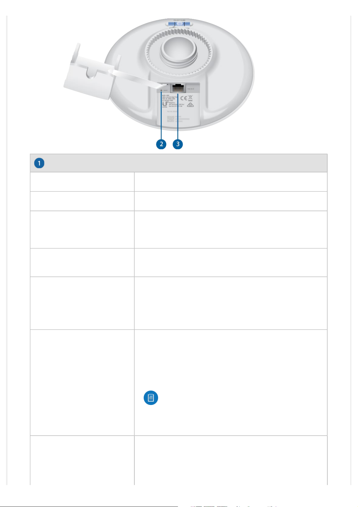
Reset Button
Resets to factory defaults. The device should be running after bootup is complete. Press
and hold the Reset button for about 10 seconds until the LED starts flashing and then
becomes solidly lit. After a few seconds, the LED will turn off, and the device will
automatically reboot.
Note: The UBB radios are pre-paired. If a link is lost due to configuration
changes, you can reset both UBB radios to re-establish the link.
Ethernet Port
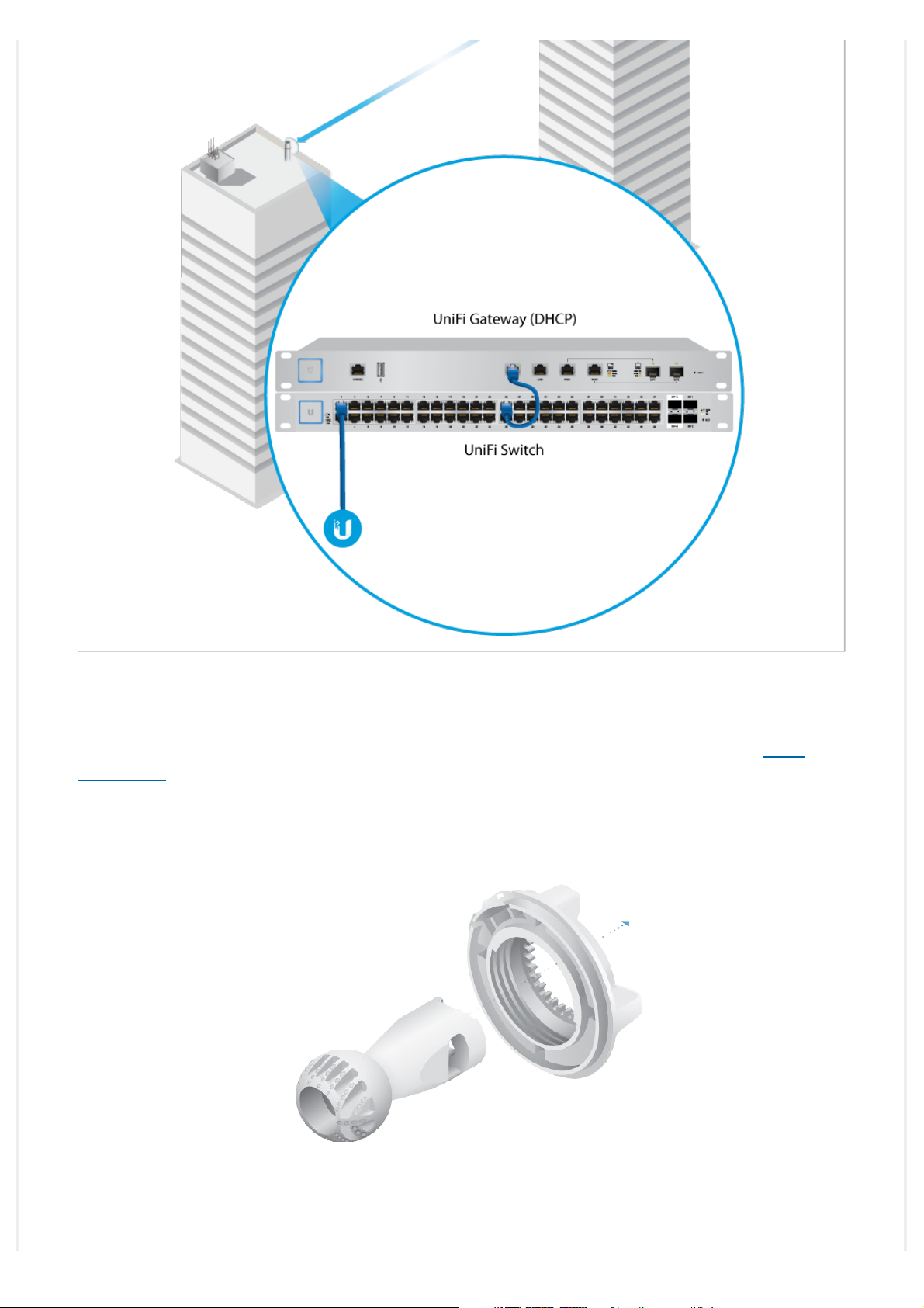
Local UBB radio (source LAN) This Gigabit Ethernet port is used to connect the power and
should be connected to the LAN and DHCP server.
recommend moving the UBB device up or
down until the LED is green.
Remote UBB radio (bridged LAN) This Gigabit Ethernet port is used to connect the power
and should be connected to the LAN. It will receive its IP address from the DHCP server via
the wireless link to the local UBB radio.
Hardware Installation
For each UBB radio, go to the appropriate mounting instructions: Pole Mounting or “Wall
Mounting”.
Pole-Mounting
1.
2.

3.
4.
 Loading...