


UBIQUITI UBI UAP-AC-LR5 Quick Installation Guide
802.11AC Scalable
Enterprise Wi-Fi Technology
Model: UAP-AC-LR
Introduction
Thank you for purchasing the Ubiquiti Networks® UniFi®AP.
This Quick Start Guide is designed to guide you through
installation and also includes warranty terms.
IMPORTANT:
v4.7 or higher, available at: downloads.ubnt.com/unifi
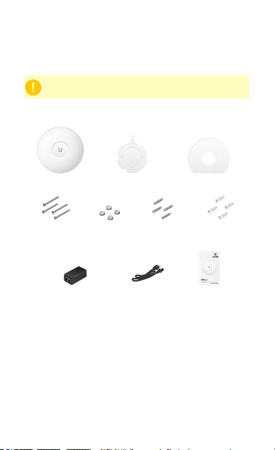
Package Contents
UniFi AP AC LR Mounting Bracket Ceiling Backing Plate
The UAP-AC-LR requires the UniFi Controller
Flat Head Screws
(M3x50, Qty. 4)
Gigabit PoE* (24V, 0.5A)
with Mounting Bracket
* Included only in the single-pack of the UAP-AC-LR.
Keps Nuts
(M3, Qty. 4)
Screws
(M2.9x20, Qty. 4)
Power Cord* Quick Start Guide
Screw Anchors
(M3x20, Qty. 4)
802.11AC Scalable
Enterprise Wi-Fi Technology
Model: UAP-AC-LR
Installation Requirements
• CAT5/6 cable
• Phillips screwdriver
• Drill and drill bit (6 mm for wall-mounting or 3 mm for
ceiling-mounting)
• Optional: Drywall or keyhole saw (to cut 18 mm hole for
Ethernet cable feed)
TERMS OF USE: All Ethernet cabling runs must use CAT5 (or above). It is the customer’s
responsibility to follow local country regulations, including operation within legal frequency
channels, output power, indoor cabling requirements, and Dynamic Frequency Selection
(DFS) requirements.
System Requirements
UAP-AC Outdoor
Management
Internet
• Linux, MacOSX, or Microsoft Windows 7/8
• Java Runtime Environment 1.6 (or above)
• Web Browser: Mozilla Firefox, Google Chrome, or Microsoft
Internet Explorer 10 (or above)
• UniFi Controller software v4.7 or higher (available at:
downloads.ubnt.com/unifi)
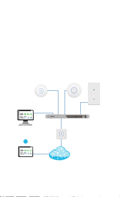
Network Topology Requirements
• A DHCP-enabled network (for the AP to obtain an IP address
as well as for the wireless clients after deployment)
• A management station running the UniFi Controller
software, located either on-site and connected to the same
Layer-2 network, or off-site in a cloud or NOC
CURRENT SITE
Default
DASHBOARD
Network Health
MAP
DEVICES
CLIENTS
CALLS
STATISTICS
INSIGHTS
SETTINGS
On-Site
Station
or
CURRENT SITE
Default
DASHBOARD
Network Health
MAP
DEVICES
CLIENTS
CALLS
STATISTICS
INSIGHTS
SETTINGS
O-Site
Cloud/NOC
REFRESH RATE
2 minutes
REFRESH RATE
2 minutes
UAP-AC-LR
LAN
WAN
UAP-PRO
UniFi Switch
UniFi
Security
Gateway
Sample Network Diagram
All UniFi devices support off-site management controllers.
For setup details, see the User Guide on the website:
documentation.ubnt.com/unifi
1G
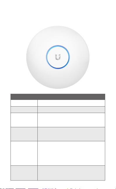
Hardware Overview
LED
LED Color Status
White
Flashing White
Alternating
White/Blue
Blue
Quickly
Flashing Blue
Steady Blue
with occasional
flashing
Factory default, waiting to be integrated.
Initializing.
Device is busy; do not touch or unplug it.
This usually indicates that a process such
as a firmware upgrade is taking place.
Indicates the device has been successfully
integrated into a network and is working
properly.
This is used to locate an AP.
When you click Locate in the UniFi
Controller software, the LED on the AP will
flash. It will also display the location of the
AP on the map.
Indicates the device is in an isolated state
(all WLANs are brought down until an
uplink is found).
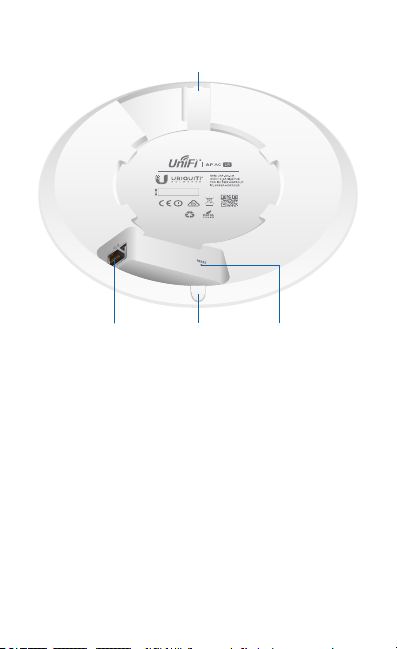
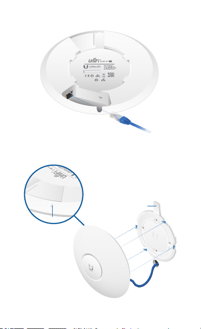
Ports
Locking Notch
Cable Feed Plug
Locking Notch The Locking Notch will be used with the
Mounting Bracket to help secure the UniFi AP. (This is described
further in the Mounting Bracket section.)
Ethernet This Gigabit Ethernet port is used to connect the
power and should be connected to the LAN and DHCP server.
Power can be provided by a Ubiquiti Networks UniFi Switch or
Gigabit PoE adapter (included with single-pack only).
Reset ButtonEthernet Port
Reset The Reset button serves two functions for the UniFi AP:
• Restart Press and release the Reset button quickly.
• Restore to Factory Default Settings Press and hold the
Reset button for more than five seconds.
Alternatively, the UniFi AP may be reset remotely via a Reset
button located on the bottom of the Gigabit PoE adapter.
Cable Feed Plug If your Ethernet cable feeds along the
mounting surface, remove the Cable Feed Plug.
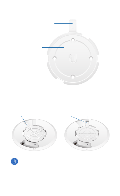
Mounting Bracket
Locking Tab
Mounting Bracket
Locking Tab During installation, the Locking Tab on the
Mounting Bracket moves from the Initial Position to the Final
Position, where the Locking Tab fits securely into the Locking
Notch on the UniFi AP to help prevent theft.
Initial Position SlotFinal Position
Note:
If you need to remove the UniFi AP from the
Mounting Bracket, insert a paper clip in the Slot to release
the Locking Tab and turn the UniFi AP counterclockwise.
Hardware Installation
The UniFi AP can be mounted on the wall or ceiling. Perform
the steps for the appropriate installation:
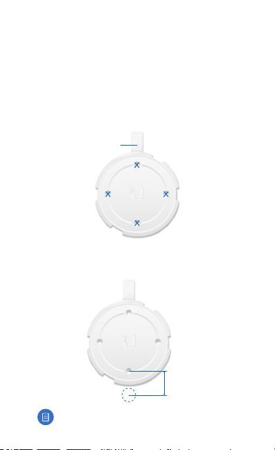
Wall Mount
1. Position the Mounting Bracket at the desired location on
the wall with the arrow pointing up.
2. Use a pencil to mark the four mounting holes. Use a 6 mm
drill bit to drill the mounting holes.
Arrow
3. If your Ethernet cable feeds through the wall, then cut or
drill a circle approximately 18 mm in diameter. Then feed
the CAT5/6 cable through the hole.
25 mm
Note: 25 mm is the distance from the center of the
bottom mounting hole to the center of the cable hole.
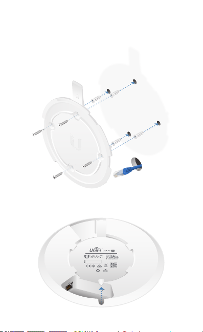
4. Insert the Screw Anchors into the 6 mm holes. Secure the
Mounting Bracket to the wall by inserting the Screws into
the anchors.
5. If the Ethernet cable runs along the mounting surface, then
remove the Cable Feed Plug.
6. Connect the Ethernet cable to the Ethernet port.
7. Align the arrow on the UniFi AP with the arrow on the
Locking Tab of the Mounting Bracket.
Locking Tab
Arrow