

Page 1
Compact 802.11ac Wave 2
Enterprise Access Point
Model: UAP-nanoHD
Page 2
Introduction
Thank you for purchasing the Ubiquiti Networks® UniFi®
802.11ac Wave 2 Enterprise Access Point. This Quick Start
Guide is designed to guide you through installation and
includes warranty terms.
IMPORTANT:
Controller
www.ubnt.com/download/unifi
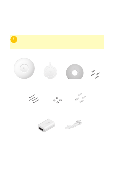
Package Contents
The UAP-nanoHD requires the UniFi
v5.7 or higher, available at:
UniFi nanoHD AP Mounting Bracket Ceiling Backing
Flat Head Screws
(Qty. 4)
Gigabit PoE* (48V, 0.5A)
* Included only in the single-pack of the UAP-nanoHD
TERMS OF USE: All Ethernet cabling runs must use CAT5 (or above). It is the professional
installer’s responsibility to follow local country regulations, including operation within legal
frequency channels, output power, indoor cabling requirements, and Dynamic Frequency
Selection (DFS) requirements.
Keps Nuts
(Qty. 4)
with Mount Bracket
Plate
Screw Anchors
Power Cord*
(Qty. 4)
Screws
(Qty. 4)
Page 3

Installation Requirements
• CAT5 cable
• Phillips screwdriver
• Drill and drill bit (6 mm for wall-mounting or 3 mm for
ceiling-mounting)
• Optional: Drywall or keyhole saw (to cut 18 mm hole for
Ethernet cable feed)
System Requirements
• Microsoft Windows 7/8/10, MacOSX, or Linux
• Java Runtime Environment 1.8 (or above)
• Web Browser: Google Chrome (Other browsers may have
limited functionality.)
• UniFi Controller software v5.7 or higher (available at:
www.ubnt.com/download/unifi)
Page 4
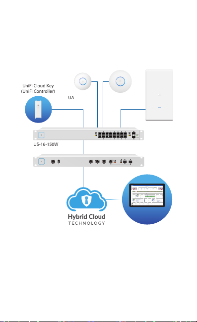
Network Topology Requirements
UAP-AC-M-PRO
(UniFi Controller)
Good
Fair
Poor
Great
Network:
Switches12Gateway
Ulizaon
18%
Internet
Capacity
43%
Clients
412
Guests
113
IoT
45
Everything is
great
My Dashboard
Edit Widgets
-24hrs
-24hrs
Max
980
Min
0
Now
Now
Throughput
Latency
ISP Load:
Great
-24hrs
Max
0
Now
Airme
-24hrs
High
Low
Now
Retry Rate
Great
Wi-Fi Load:
225.2 Mbps
125.2 Mbps
1
Wi-Fi Traffic Distribuon
3661140444852566064100
104
108
112
116
120
124
128
132
136
140
149
153
157
161
165
5 GHz
2.4 GHz
Access Points
20
Last 24 Hrs
Most Acve APs
Office
Back Room
Storage
Roof
Hallway We ...
91 GB
86 GB
53 GB
48 GB
45 GB
Top 5 Applicaons
YouTube
35 Clients
Instagram
19 Clients
Squarespace
17 Clients
Google
12 Clients
Facebook
20 Clients
Top Interference
Hallway We ...
Roof
Storage
51%
45%
44%
Top CPU Usage
Office
Back Room
Home
51%
45%
43%
Most Acve Clients
Wi-Fi Key Metrics
91 Clients
iPhone
87 Clients
Android
45 Clients
MacBook
35 Clients
PC Laptop
12 Clients
iPad
Top Memory Usage
Client Frequency Distribuon
Device Distribuon
HD-Kitchen
HD-Conference
Storage
Roof
Hallway We ...
56.9%
35.6%
34%
28%
24%
Longest Client Upme
Wi-Fi Summary
Roung Ulizaon
Switch Summary
iPad-1
APs Online
Gateway - USG Main
Controller - Office CK
Controller - Office 2 CK
25% CPU Ulizaon
50% CPU Ulizaon
33% CPU Ulizaon
Online
MBP-2
Clients
iPad-2
Ulizaon
Clients
Port Ulizaon
8d 4h 0m3224
2d 8h 30m
1,324
2d 5h 15m
64%
1,324
32%
Port Usage
VPN Name
Status
Users
Guests
Purpose
Average Data
Port 1- GB
VPN-LA-PDX
212Corporate
320 GB
Port 2- GB POE+
VPN-LA-PDX2
60VLAN Only
11 GB
Port 3- 10 GB
Remote-Office-1
430VLAN Only
12 GB
1208032
HD-Conference
42%
Office - Art Dept
42%
MBP-1
Traffic
Devices
Traffic
2d 3h 10m
248 GB
536
1,248 GB
Port 4- GB POE
Transfer-1
712VLAN Only
0 GB
13
5GHz
50%
13 LAN
03 WLAN
01 WAN
0%
0%
0%
100%
100%
100%
Average Capacity
500 Mbps
Average Airme Ulizaon8%Average Spectral Efficiency
2.1 (b/s) Hz
64% 11ac W2
28% 11ac
08% 11n
1300 Mbps
0 Mbps
100%
0%
(b/s) Hz
3.76 (b/s) Hz
Internet Connecon:
30 Mbps
40 Mbps
50 Mbps
20 Mbps
10 Mbps
0 Mbps
-24 hrs
-12 hrs
Now
Download
Theorecal Capacity
Throughput
Portlan d
SDN
Most Acve Switches
• A DHCP-enabled network (for the AP to obtain an IP address
as well as for the wireless clients after deployment)
• A UniFi Cloud Key or management station running the UniFi
Controller software, located either on-site and connected to
the same Layer-2 network, or off-site in the cloud or a NOC
UniFi Cloud Key
UAP-nanoHD
UAP-AC-HD
US-16-150W
USG-PRO-4
(DHCP Server)
LAN
WAN
Internet
Remote Access to
UniFi Controller
Sample Network Diagram
All UniFi devices support off-site management controllers. For
setup details, see the User Guide on the website:
www.ubnt.com/download/unifi
SW-24A
56.9%
SW-8A
35.6%
SW-8B
34%
SW-24E
28%
SW-24D
24%
Page 5
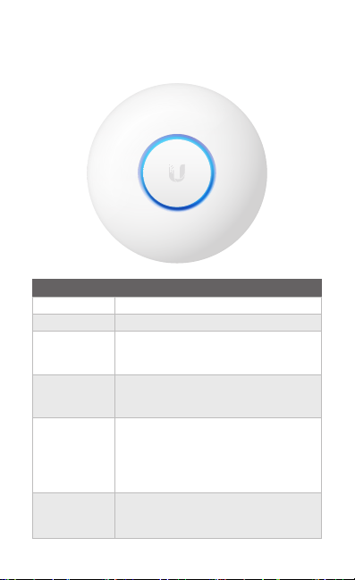
Hardware Overview
LED
LED Color Status
White Factory default, waiting to be adopted.
Flashing White Initializing.
Alternating
White/Blue
Blue
Quickly
Flashing Blue
Steady Blue
with Occasional
Flashing
Device is busy; do not touch or unplug it.
This usually indicates that a process such
as a firmware upgrade is taking place.
Indicates the device has been successfully
adopted by a network and is working
properly.
This is used to locate an AP.
When you click Locate in the UniFi
Controller software, the LED on the AP will
flash. It will also display the location of the
AP on the map.
Indicates the device is in an isolated state
(all WLANs are brought down until an
uplink is found).
Page 6
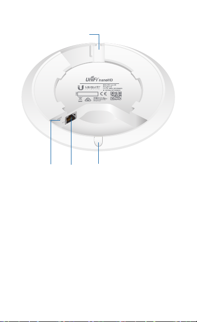
Ports
Locking Notch
Ethernet
Port
Cable
Feed Plug
Reset
Button
Locking Notch The Locking Notch will be used with the
Mounting Bracket to help secure the UniFi AP. (This is described
further in the Mounting Bracket section.)
Ethernet This Gigabit Ethernet port is used to connect the
power and should be connected to the LAN and DHCP server.
Reset The Reset button serves two functions for the UniFi AP:
• Restart Press and release the Reset button quickly.
• Restore to Factory Default Settings Press and hold the
Reset button for more than five seconds.
Cable Feed Plug If your Ethernet cable feeds along the
mounting surface, remove the Cable Feed Plug.
Page 7
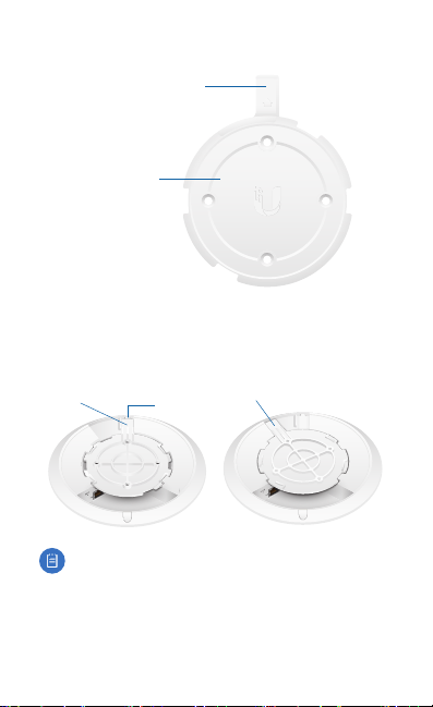
Mounting Bracket
Locking Tab
Mounting Bracket
Locking Tab During installation, the Locking Tab on the
Mounting Bracket moves from the Initial Position to the Final
Position, where the Locking Tab fits securely into the Locking
Notch on the UniFi AP to help prevent theft.
Final Position
Note:
Mounting Bracket, insert a paper clip in the Slot to release
the Locking Tab and turn the UniFi AP counterclockwise.
Slot
If you need to remove the UniFi AP from the
Initial Position
Page 8
Hardware Installation
The UniFi AP can be mounted on the wall or ceiling. Perform
the steps for the appropriate installation:
Wall Mount
1. Position the Mounting Bracket at the desired location on
the wall with the arrow pointing up.
2. Use a pencil to mark the four mounting holes. Use a 6 mm
drill bit to drill the mounting holes.
Arrow
3. If your Ethernet cable feeds through the wall, then cut or
drill a circle approximately 18 mm in diameter. Then feed
the CAT5 cable through the hole.
25 mm
Note: 25 mm is the distance from the center of the
bottom mounting hole to the center of the cable hole.
Page 9
4. Insert the Screw Anchors into the 6 mm holes. Secure the
Mounting Bracket to the wall by inserting the Screws into
the anchors.
5. If the Ethernet cable runs along the mounting surface,
remove the Cable Feed Plug.
Page 10

6. Connect the Ethernet cable to the Ethernet port.
7. Align the arrow on the UniFi AP with the arrow on the
Locking Tab of the Mounting Bracket.
Locking Tab
Arrow
Page 11

8. Ensure that the UniFi AP is firmly seated on the Mounting
Bracket. Turn the UniFi AP clockwise until it locks into place
and the Locking Tab fits securely into the Locking Notch.
Page 12

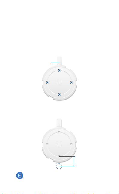
Ceiling Mount
1. Remove the ceiling tile.
2. Place the Ceiling Backing Plate in the center of the ceiling
tile. Mark the four mounting screw holes.
3. Mark a hole approximately 18 mm in diameter for the
Ethernet cable feed.
25 mm
Note: 25 mm is the distance from the center of the
bottom mounting hole to the center of the cable hole.
4. Use a 3 mm drill bit to drill the screw holes, and cut or drill
the hole for the Ethernet cable feed.
Page 13

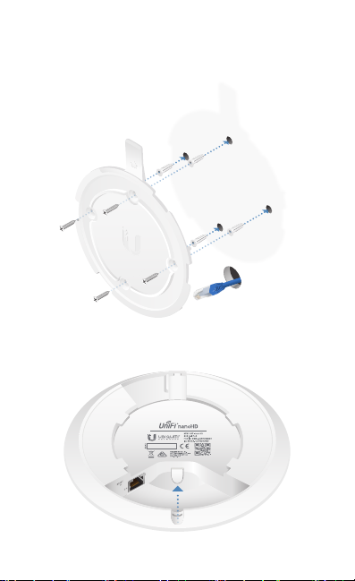
5. Insert the Flat Head Screws through the Mounting Bracket,
ceiling tile, and Ceiling Backing Plate. Fasten the screws
using the Keps Nuts. Then feed the Ethernet cable through
the 18 mm hole.
Page 14
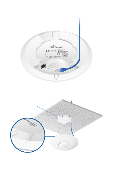
6. Connect the Ethernet cable to the Ethernet port.
7. Align the arrow on the UniFi AP with the arrow on the
Locking Tab of the Mounting Bracket.
Locking Tab
Arrow
Page 15

8. Ensure that the UniFi AP is firmly seated on the Mounting
Bracket. Turn the UniFi AP clockwise until it locks into place
and the Locking Tab fits securely into the Locking Notch.
9. Set the ceiling tile back into place.
Page 16

Powering the UniFi AP
The UAP-nanoHD features auto-sensing 802.3af PoE support
and can be powered by any of the following:
• Ubiquiti Networks UniFi Switch with PoE
• 802.3af PoE compliant switch
• Ubiquiti Networks Gigabit PoE Adapter (48V, 0.5A)
The single-pack of the UAP-nanoHD includes one Gigabit PoE
adapter. For multi-pack units, PoE adapters or a UniFi Switch
with PoE may be purchased separately.
Connecting to a PoE Switch
Connect the Ethernet cable from the UniFi AP directly to an
802.3af-compliant port on the switch.
Page 17

Connecting Power over Ethernet
1. Connect the Ethernet cable from the device to the
adapter’s POE port.
2. Connect an Ethernet cable from your LAN to the adapter’s
LAN port.
3. Connect the Power Cord to the adapter’s power port.
Connect the other end of the Power Cord to a power outlet.
Mounting the PoE Adapter (Optional)
1. Remove the PoE Mounting Bracket from the adapter, place
the bracket at the desired location, and mark the two holes.
2. Pre-drill the holes if necessary, and secure the bracket
using two fasteners (not included).
3. Align the adapter’s slots with the tabs of the PoE Mounting
Bracket, and then slide the adapterdown.
Page 18

Software Installation
Download and install the latest version of the UniFi Controller
software. Launch it and follow the on-screen instructions. The
software and step-by-step instructions in the User Guide are
available at: www.ubnt.com/download/unifi
After you have installed the software and run the UniFi
Installation Wizard, a login screen will appear for the UniFi
Controller management interface. Enter the Admin Name and
Password that you created and click Sign In.
Mobile App Installation
Ubiquiti Networks also offers the UniFi app, which is available
from the App Store® (iOS) or Google Play™ Store (Android).
You can use it to provision a UniFi AP for basic functionality
without configuring a UniFi Controller. It also allows seamless
provisioning of APs for remote controllers (controllers not on
the same Layer 2 network) and easy access to local controllers
and those monitored on unifi.ubnt.com
Page 19
Specifications
Dimensions 160 x 160 x 32.65 mm
Weight
With Mounting Kits
Networking Interface (1) RJ45 GbE
Buttons (1) Reset to Defaults
Power Method 802.3af
Power Supply 48V, 0.5A Gigabit PoE Adapter*
Max. Power Consumption 10.5W
Operating Frequency 2.4 GHz
Max. TX Power
2.4 GHz
5 GHz
Antenna Gain
2.4 GHz
5 GHz
MIMO
2.4 GHz
5 GHz
Radio Rate
2.4 GHz
5 GHz
Wi-Fi Standards 802.11 a/b/g/n/ac/ac-wave2
Wireless Security WEP, WPA-PSK,
BSSID 8 per Radio
Mounting Wall/Ceiling (Kits Included)
Operating Temperature -10 to 70° C (14 to 158° F)
Operating Humidity 5 to 95% Noncondensing
Certications CE, FCC, IC
* Only the single-pack of the UAP-nanoHD includes a PoE adapter.
UAP-nanoHD
(6.3 x 6.3 x 1.29")
WPA-Enterprise (WPA/WPA2, TKIP/AES)
300 g (10.6 oz)
315 g (11.1 oz)
5 GHz
23 dBm
26 dBm
2.8 dBi
300 Mbps
1733 Mbps
3 dBi
2x2
4x4
Page 20

Safety Notices
1. Read, follow, and keep these instructions.
2. Heed all warnings.
3. Only use attachments/accessories specified by the manufacturer.
WARNING: Do not use this product in a location that can
be submerged by water.
WARNING: Avoid using this product during an electrical
storm. There may be a remote risk of electric shock from
lightning.
Electrical Safety Information
1. Compliance is required with respect to voltage, frequency, and current
requirements indicated on the manufacturer’s label. Connection to a
different power source than those specified may result in improper
operation, damage to the equipment or pose a fire hazard if the
limitations are not followed.
2. There are no operator serviceable parts inside this equipment. Service
should be provided only by a qualified service technician.
3. This equipment is provided with a detachable power cord which has
an integral safety ground wire intended for connection to a grounded
safety outlet.
a. Do not substitute the power cord with one that is not the provided
approved type. Never use an adapter plug to connect to a 2-wire
outlet as this will defeat the continuity of the grounding wire.
b. The equipment requires the use of the ground wire as a part of the
safety certification, modification or misuse can provide a shock
hazard that can result in serious injury or death.
c. Contact a qualified electrician or the manufacturer if there
are questions about the installation prior to connecting the
equipment.
d. Protective earthing is provided by Listed AC adapter. Building
installation shall provide appropriate short-circuit backup
protection.
e. Protective bonding must be installed in accordance with local
national wiring rules and regulations.
Page 21

Limited Warranty
www.ubnt.com/support/warranty/
The limited warranty requires the use of arbitration to resolve disputes on
an individual basis, and, where applicable, specify arbitration instead of
jury trials or class actions.
Compliance
FCC
Changes or modifications not expressly approved by the party responsible
for compliance could void the user’s authority to operate the equipment.
This device complies with Part 15 of the FCC Rules. Operation is subject to
the following two conditions.
1. This device may not cause harmful interference, and
2. This device must accept any interference received, including
interference that may cause undesired operation.
This equipment has been tested and found to comply with the limits for a
Class A digital device, pursuant to Part 15 of the FCC Rules. These limits are
designed to provide reasonable protection against harmful interference
when the equipment is operated in a commercial environment. This
equipment generates, uses, and can radiate radio frequency energy and,
if not installed and used in accordance with the instruction manual, may
cause harmful interference to radio communications. Operations of this
equipment in a residential area is likely to cause harmful interference in
which case the user will be required to correct the interference at his own
expense.
This radio transmitter (FCC ID: SWX-UAPHDNANO) has been approved
by FCC.
Page 22

ISED Canada
CAN ICES-3(A)/NMB-3(A)
This device complies with ISED Canada licence-exempt RSS standard(s).
Operation is subject to the following two conditions:
1. This device may not cause interference, and
2. This device must accept any interference, including interference that
may cause undesired operation of the device.
This radio transmitter (IC: 6545A-UAPHDNANO) has been approved by
ISED Canada.
The device for operation in the band 5150-5250 MHz is only for indoor
use to reduce the potential for harmful interference to co-channel mobile
satellite systems.
CAN ICES-3(A)/NMB-3(A)
Le présent appareil est conforme aux CNR d’ISDE Canada applicables aux
appareils radio exempts de licence. L’exploitation est autorisée aux deux
conditions suivantes :
1. l’appareil ne doit pas produire de brouillage;
2. l’appareil doit accepter tout brouillage radioélectrique subi, même si le
brouillage est susceptible d’en compromettre le fonctionnement.
Le présent émetteur radio (IC : 6545A-UAPHDNANO) a été approuvé par
ISDE Canada.
Les dispositifs fonctionnant dans la bande 5150-5250 MHz sont réservés
uniquement pour une utilisation à l’intérieur afin de réduire les risques
de brouillage préjudiciable aux systèmes de satellites mobiles utilisant les
mêmes canaux.
Page 23

RF Exposure Warning
The antennas used for this transmitter must be installed to provide a
separation distance of at least 20 cm from all persons and must not be
located or operating in conjunction with any other antenna or transmitter.
Les antennes utilisées pour ce transmetteur doivent être installé en
considérant une distance de séparation de toute personnes d’au moins
20 cm et ne doivent pas être localisé ou utilisé en conflit avec tout autre
antenne ou transmetteur.
Australia and New Zealand
Warning: This is a Class A product. In a domestic environment this
product may cause radio interference in which case the user may
be required to take adequate measures.
Brazil
Nota: Este equipamento não tem direito à proteção contra
interferência prejudicial e não pode causar interferência em
sistemas devidamente autorizados.
CE Marking
CE marking on this product represents the product is in compliance with
all directives that are applicable to it.
AT BE BG CY CZ DE DK EE EL ES FI FR HR HU
IE IT LV LT LU MT NL PL PT RO SE SI SK UK
BFWA (Broadband Fixed Wireless Access) members noted in blue
Note: This device meets Max. TX power limit per ETSI regulations.
The following apply to products that operate in the 5 GHz frequency range:
Note: This device is restricted to indoor use only when operating
in the 5150 - 5350 MHz frequency range within all member states.
Note: All countries listed may operate at 30 dBm. BFWA member
states may operate at 36 dBm.
Note: Operation in the 5.8 GHz frequency band is prohibited in
BFWA member states. Other countries listed may use the 5.8 GHz
frequency band.
Country List
Page 24

RoHS/WEEE Compliance Statement
English
European Directive 2012/19/EU requires that the equipment bearing
this symbol on the product and/or its packaging must not be disposed
of with unsorted municipal waste. The symbol indicates that this
product should be disposed of separately from regular household waste
streams. It is your responsibility to dispose of this and other electric and
electronic equipment via designated collection facilities appointed by the
government or local authorities. Correct disposal and recycling will help
prevent potential negative consequences to the environment and human
health. For more detailed information about the disposal of your old
equipment, please contact your local authorities, waste disposal service, or
the shop where you purchased the product.
Deutsch
Die Europäische Richtlinie 2012/19/EU verlangt, dass technische
Ausrüstung, die direkt am Gerät und/oder an der Verpackung mit diesem
Symbol versehen ist, nicht zusammen mit unsortiertem Gemeindeabfall
entsorgt werden darf. Das Symbol weist darauf hin, dass das Produkt
von regulärem Haushaltmüll getrennt entsorgt werden sollte. Es
liegt in Ihrer Verantwortung, dieses Gerät und andere elektrische
und elektronische Geräte über die dafür zuständigen und von der
Regierung oder örtlichen Behörden dazu bestimmten Sammelstellen zu
entsorgen. Ordnungsgemäßes Entsorgen und Recyceln trägt dazu bei,
potentielle negative Folgen für Umwelt und die menschliche Gesundheit
zu vermeiden. Wenn Sie weitere Informationen zur Entsorgung Ihrer
Altgeräte benötigen, wenden Sie sich bitte an die örtlichen Behörden oder
städtischen Entsorgungsdienste oder an den Händler, bei dem Sie das
Produkt erworben haben.
Page 25

Español
La Directiva 2012/19/UE exige que los equipos que lleven este símbolo en
el propio aparato y/o en su embalaje no deben eliminarse junto con otros
residuos urbanos no seleccionados. El símbolo indica que el producto
en cuestión debe separarse de los residuos domésticos convencionales
con vistas a su eliminación. Es responsabilidad suya desechar este y
cualesquiera otros aparatos eléctricos y electrónicos a través de los puntos
de recogida que ponen a su disposición el gobierno y las autoridades
locales. Al desechar y reciclar correctamente estos aparatos estará
contribuyendo a evitar posibles consecuencias negativas para el medio
ambiente y la salud de las personas. Si desea obtener información más
detallada sobre la eliminación segura de su aparato usado, consulte a las
autoridades locales, al servicio de recogida y eliminación de residuos de su
zona o pregunte en la tienda donde adquirió el producto.
Français
La directive européenne 2012/19/UE exige que l’équipement sur lequel
est apposé ce symbole sur le produit et/ou son emballage ne soit pas jeté
avec les autres ordures ménagères. Ce symbole indique que le produit
doit être éliminé dans un circuit distinct de celui pour les déchets des
ménages. Il est de votre responsabilité de jeter ce matériel ainsi que tout
autre matériel électrique ou électronique par les moyens de collecte
indiqués par le gouvernement et les pouvoirs publics des collectivités
territoriales. L’élimination et le recyclage en bonne et due forme ont pour
but de lutter contre l’impact néfaste potentiel de ce type de produits
sur l’environnement et la santé publique. Pour plus d’informations sur le
mode d’élimination de votre ancien équipement, veuillez prendre contact
avec les pouvoirs publics locaux, le service de traitement des déchets, ou
l’endroit où vous avez acheté le produit.
Italiano
La direttiva europea 2012/19/UE richiede che le apparecchiature
contrassegnate con questo simbolo sul prodotto e/o sull’imballaggio non
siano smaltite insieme ai rifiuti urbani non differenziati. Il simbolo indica
che questo prodotto non deve essere smaltito insieme ai normali rifiuti
domestici. È responsabilità del proprietario smaltire sia questi prodotti sia
le altre apparecchiature elettriche ed elettroniche mediante le specifiche
strutture di raccolta indicate dal governo o dagli enti pubblici locali. Il
corretto smaltimento ed il riciclaggio aiuteranno a prevenire conseguenze
potenzialmente negative per l’ambiente e per la salute dell’essere umano.
Per ricevere informazioni più dettagliate circa lo smaltimento delle vecchie
apparecchiature in Vostro possesso, Vi invitiamo a contattare gli enti
pubblici di competenza, il servizio di smaltimento rifiuti o il negozio nel
quale avete acquistato il prodotto.
Page 26

Declaration of Conformity
български [Bulgarian] С настоящото UBIQUITI NETWORKS декларира, че този тип
радиосъоръжение UAP-nanoHD е в съответствие с Директива 2014/53/ЕС. Цялостният
текст на ЕС декларацията за съответствие може да се намери на следния интернет адрес:
www.ubnt.com/compliance
Hrvatski [Croatian] UBIQUITI NETWORKS ovime izjavljuje da je radijska oprema tipa
UAP-nanoHD u skladu s Direktivom 2014/53/EU. Cjeloviti tekst EU izjave o sukladnosti dostupan
je na sljedećoj internetskoj adresi:
Čeština [Czech] Tímto UBIQUITI NETWORKS prohlašuje, že typ rádiového zařízení UAP-nanoHD
je v souladu se směrnicí 2014/53/EU. Úplné znění EU prohlášení o shodě je k dispozici na této
internetové adrese:
Dansk [Danish] Hermed erklærer UBIQUITI NETWORKS, at radioudstyrstypen UAP-nanoHD er i
overensstemmelse med direktiv 2014/53/EU. EU-overensstemmelseserklæringens fulde tekst kan
findes på følgende internetadresse:
Nederlands [Dutch] Hierbij verklaar ik, UBIQUITI NET WORKS, dat het type radioapparatuur
UAP-nanoHD conform is met Richtlijn 2014/53/EU. De volledige tekst van de
EU-conformiteitsverklaring kan worden geraadpleegd op het volgende internetadres:
www.ubnt.com/compliance
English
Hereby, UBIQUITI NETWORKS declares that the radio equipment type
is in compliance with Directive 2014/53/EU. The full text of the EU declaration of conformity is
available at the following internet address: www.ubnt.com/compliance
Eesti keel [Estonian] Käesolevaga deklareerib UBIQUITI NETWORKS, et käesolev raadioseadme
tüüp UAP-nanoHD vastab direktiivi 2014/53/EL nõuetele. ELi vastavusdeklaratsiooni täielik tekst
on kättesaadav järgmisel internetiaadressil:
Suomi [Finnish] UBIQUITI NETWORKS vakuuttaa, että radiolaitetyyppi UAP-nanoHD on direktiivin
2014/53/EU mukainen. EU-vaatimustenmukaisuusvakuutuksen täysimittainen teksti on saatavilla
seuraavassa internetosoitteessa:
Français [French] Le soussigné, UBIQUITI NETWORKS, déclare que l’équipement radioélectrique
du type UAP-nanoHD est conforme à la directive 2014/53/UE. Le texte complet de la déclaration
UE de conformité est disponible à l’adresse internet suivante:
Deutsch [German] Hiermit erklärt UBIQUITI NET WORKS, dass der Funkanlagentyp UAP-nanoHD
der Richtlinie 2014/53/EU entspricht. Der vollständige Text der EU-Konformitätserklärung ist unter
der folgenden Internetadresse verfügbar:
Ελληνικά [Greek] Με την παρούσα ο/η UBIQUITI NETWORKS, δηλώνει ότι ο ραδιοεξοπλισμός
UAP-nanoHD πληροί την οδηγία 2014/53/ΕΕ. Το πλήρες κείμενο της δήλωσης συμμόρφωσης ΕΕ
διατίθεται στην ακόλουθη ιστοσελίδα στο διαδίκτυο:
Magyar [Hungarian] UBIQUITI NETWORKS igazolja, hogy a UAP-nanoHD típusú rádióberendezés
megfelel a 2014/53/EU irányelvnek. Az EU-megfelelőségi nyilatkozat teljes szövege elérhető a
következő internetes címen:
Íslenska [Icelandic] Hér með lýsir UBIQUITI NETWORKS yfir því að UAP-nanoHD er í samræmi
við grunnkröfur og aðrar kröfur, sem gerðar eru í tilskipun 2014/53/EU. Fullur texti ESB
samræmisyfirlýsing er að finna á eftirfarandi netfangi:
Italiano [Italian] Il fabbricante, UBIQUITI NETWORKS, dichiara che il tipo di apparecchiatura
radio UAP-nanoHD èconforme alla direttiva 2014/53/UE. Il testo completo della dichiarazione di
conformità UE è disponibile al seguente indirizzo Internet:
Latviešu valoda [Latvian] Ar šo UBIQUITI NETWORKS deklarē, ka radioiekār ta UAP-nanoHD atbilst
Direktīvai 2014/53/ES. Pilns ES atbilstības deklarācijas teksts ir pieejams šādā interneta vietnē:
www.ubnt.com/compliance
Lietuvių kalba [Lithuanian] Aš, UBIQUITI NETWORKS, patvirtinu, k ad radijo įrenginių tipas
UAP-nanoHD atitinka Direktyvą 2014/53/ES. Visas ES atitikties deklaracijos tekstas prieinamas šiuo
interneto adresu:
www.ubnt.com/compliance
www.ubnt.com/compliance
www.ubnt.com/compliance
www.ubnt.com/compliance
www.ubnt.com/compliance
www.ubnt.com/compliance
www.ubnt.com/compliance
www.ubnt.com/compliance
www.ubnt.com/compliance
www.ubnt.com/compliance
www.ubnt.com/compliance
www.ubnt.com/compliance
UAP-nanoHD
Page 27

Malti [Maltese]
B’dan, UBIQUITI NETWORKS, niddikjara li dan it-tip ta’ tagħmir tar-radju
UAP-nanoHD
huwa konformi mad-Direttiva 2014/53/UE. Id-dikjarazzjoni tal-konformità tista’ tiġi
kkonsultata minn www.ubnt.com/compliance
Norsk [Norwegian]
samsvar med de grunnleggende krav og øvrige relevante krav i direktiv 2014/53/EU. Den
fulle teksten til EU-samsvarserklæringen er tilgjengelig på følgende internettadresse:
www.ubnt.com/compliance
Polski [Polish] UBIQUITI NETWORKS niniejszym oświadcza, że typ urządzenia radiowego
UAP-nanoHD jest zgodny z dyrektywą 2014/53/UE. Pełny tekst deklaracji zgodności UE jest
dostępny pod następującym adresem internetowym:
Português [Portuguese] O(a) abaixo assinado(a) UBIQUITI NETWORKS declara que o presente
tipo de equipamento de rádio UAP-nanoHD está em conformidade com a Diretiva 2014/53/UE.
O texto integral da declaração de conformidade está disponível no seguinte endereço de
Internet:
Română [Romanian] Prin prezenta, UBIQUITI NETWORKS declară că tipul de echipamente radio
UAP-nanoHD este în conformitate cu Directiva 2014/53/UE. Textul integral al declarației UE de
conformitate este disponibil la următoarea adresă internet:
Slovenčina [Slovak]
UAP-nanoHD je v súlade so smernicou 2014/53/EÚ. Úplné EÚ vyhlásenie o zhode je k dispozícii na
tejto internetovej adrese:
Slovenščina [Slovenian]
skladen z Direktivo 2014/53/EU. Celotno besedilo izjave EU o skladnosti je na voljo na naslednjem
spletnem naslovu: www.ubnt.com/compliance
Español [Spanish] Por la presente, UBIQUITI NETWORKS declara que el tipo de equipo
radioeléctrico UAP-nanoHD es conforme con la Directiva 2014/53/UE. El texto completo
de la declaración UE de conformidad está disponible en la dirección Internet siguiente:
www.ubnt.com/compliance
Svenska [Swedish] Härmed försäkrar UBIQUITI NETWORKS att denna typ av
radioutrustning UAP-nanoHD överensstämmer med direktiv 2014/53/EU. Den
fullständiga texten till EU-försäkran om överensstämmelse finns på följande webbadress:
www.ubnt.com/compliance
UBIQUITI NETWORKS erklærer herved at utstyret
www.ubnt.com/compliance
UBIQUITI NETWORKS
týmto vyhlasuje, že rádiové zariadenie typu
www.ubnt.com/compliance
UBIQUITI NETWORKS potrjuje, da je tip radijske opreme
UAP-nanoHD
www.ubnt.com/compliance
www.ubnt.com/compliance
er i
UAP-nanoHD
Page 28

Online Resources
Support help.ubnt.com
Community community.ubnt.com
Downloads downloads.ubnt.com
Ubiquiti Networks, Inc.
685 Third Avenue, 27th Floor
New York, NY 10017
USA
www.ubnt.com
©2017-2018 Ubiquiti Networks, Inc. All rights reserved. Ubiquiti, Ubiquiti
Networks, the Ubiquiti U logo, the Ubiquiti beam logo, and UniFi are
trademarks or registered trademarks of Ubiquiti Networks, Inc. in the United
States and in other countries. Apple and the Apple logo are trademarks of
Apple Inc., registered in the U.S. and other countries. App Store is a service
mark of Apple Inc. Android, Google, Google Play, the Google Play logo and
other marks are trademarks of Google LLC. All other trademarks are the
property of their respective owners. NB102918
 Loading...