

Ubiquiti UAP-AC-EDU User Manual

802.11ac Dual-Radio AP
with Public Address System
Model: UAP-AC-EDU
Introduction
Thank you for purchasing the Ubiquiti Networks®
UniFi®802.11ac Dual-Radio AP with Public Address System.
This Quick Start Guide is designed to guide you through
installation and also includes warranty terms.
IMPORTANT: The UAP-AC-EDU requires the UniFi Controller
v
4.9.5
or higher, available at: downloads.ubnt.com/unifi
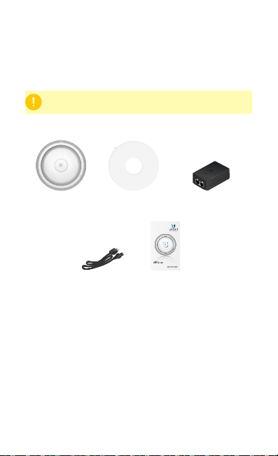
Package Contents
UniFi AP AC EDU Mounting Template Gigabit PoE* (48V, 0.5A)
Power Cord* Quick Start Guide
* Included only in the single-pack of the UAP-AC-EDU.
with Mounting Bracket
802.11ac Dual-Radio AP
with Public Address System
Model: UAP-AC-EDU
Installation Requirements
• CAT5/6 cable
• Phillips screwdriver
• Drywall or keyhole saw (to cut the hole in the ceiling tile)
TERMS OF USE: All Ethernet cabling runs must use CAT5 (or above). It is the customer’s
responsibility to follow local country regulations, including operation within legal frequency
channels, output power, indoor cabling requirements, and Dynamic Frequency Selection
(DFS) requirements.
System Requirements
(UniFi Controller)
UAP-AC Outdoor
Remote Access to
UniFi Controller
• Linux, MacOSX, or Microsoft Windows 7/8/10
• Java Runtime Environment 1.6 (1.8 or above recommended)
• Web Browser: Google Chrome (Other browsers may have
limited functionality.)
• UniFi Controller software v4.9.5 or newer (available at:
downloads.ubnt.com/unifi)
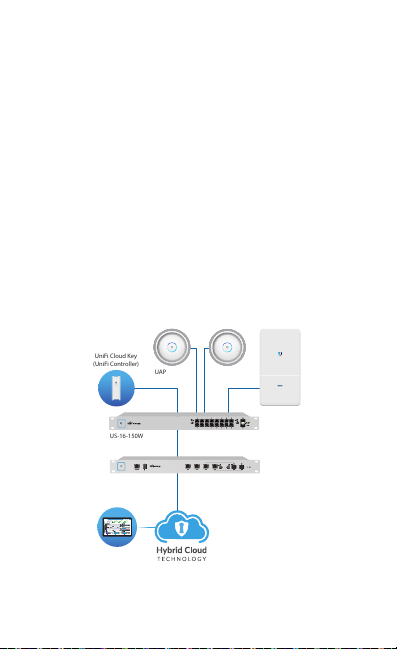
Network Topology Requirements
• A DHCP-enabled network (for the AP to obtain an IP address
as well as for the wireless clients after deployment)
• A UniFi Cloud Key or management station running the UniFi
Controller v4.9.5 (or newer) software, located either on-site
and connected to the same Layer-2 network, or off-site in
the cloud or NOC
• For public address system capability: A compatible Android™
or iOS device located on the same Layer-2 network as the
UniFi Controller and UniFi APs
UniFi Cloud Key
UAP-AC-EDU UAP-AC-EDU
All UniFi devices support off-site management controllers.
For setup details, see the User Guide on the website:
documentation.ubnt.com/unifi
US-16-150W
USG-PRO-4
(DHCP Server)
Sample Network Diagram
LAN
WAN
Internet

Hardware Overview
The UniFi AP AC EDU is comprised of the Speaker Assembly
and UniFi AP.
Speaker
Assembly
Ethernet Cable
Safety
Wire
UniFi AP
Back of the Speaker Assembly
Main Port
Main This Gigabit Ethernet port is used to connect the power
and should be connected to the LAN and DHCP server.
Clamp Bracket The four Clamp Brackets are used to secure the
UniFi AP AC EDU to the ceiling tile.
USB Cable
Clamp Bracket
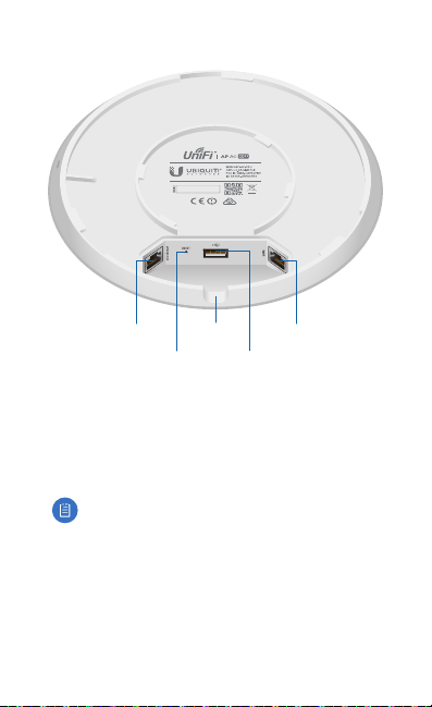
UniFi AP Ports
Secondary
Port
Reset
Button
Cable Feed
Opening
USB
Port
Main
Port
Secondary Reser ved for future use.
Reset The Reset button serves two functions for the UniFi AP:
• Restart Press and release the Reset button quickly.
• Restore to Factory Default Settings Press and hold the
Reset button for more than five seconds.
Note: You must remove the UniFi AP from the Speaker
Assembly before you can access the Resetbutton.
Alternatively, the UniFi AP may be reset remotely via a Reset
button located on the bottom of the Gigabit PoE adapter.
Cable Feed Opening The USB and Ethernet cables feed
through this opening.
USB The USB 2.0 port is used to suppor t the Speaker Assembly.
Main This Gigabit Ethernet port is used to carr y power
anddata.

LED and Microphone
Microphone
(reserved for
future use)
Color State Status
White
White/
Blue
Steady
Flashing
Alternating
Steady
Factory default, waiting for
integration.
Initializing.
Device is busy; do not touch or
unplug it. This usually indicates
that a process such as a firmware
upgrade is taking place.
Indicates the device has been
successfully integrated into a
network and is working properly.
This is used to locate an AP.
Blue
Quickly
Flashing
Steady with
occasional
flashing
When you click Locate in the UniFi
Controller software, the LED on the
AP will flash. It will also display the
location of the AP on the map.
Indicates the device is in an isolated
state (all WLANs are brought down
until an uplink is found).

Hardware Installation
1. Remove the ceiling tile.
2. Remove the backing from the Mounting Template and place
it in the center of the ceiling tile.
242 mm
3. Cut or drill a hole around the template.
4. Rotate the UniFiAP counterclockwise to release it from the
Speaker Assembly.

5. Feed an Ethernet cable through the hole and connect it to
the Main port of the Speaker Assembly.
6. If necessary, lift and rotate the Clamp Brackets so they
remain elevated and tucked against the Speaker Assembly.
Insert the Speaker Assembly into the hole.

7. We strongly recommend that you attach the Safety Wire
(length: 430 mm) to a secure structural point using its clasp
(inside diameter: 14 mm). Do NOT attach the Safety Wire to
a T-bar in the ceiling grid.
Note: It is the installer’s responsibility to verify that
installation complies with local construction and
safety codes.
Two examples are shown below.
 Loading...