

Ubiquiti ES-16-XG-US Quick Installation Guide
10G 16-Port Managed
Aggregation Switch
Model: ES-16-XG
Introduction
Thank you for purchasing the Ubiquiti Networks® EdgeSwitch™
XG. This Quick Start Guide is designed to guide you through
installation and also includes warranty terms.
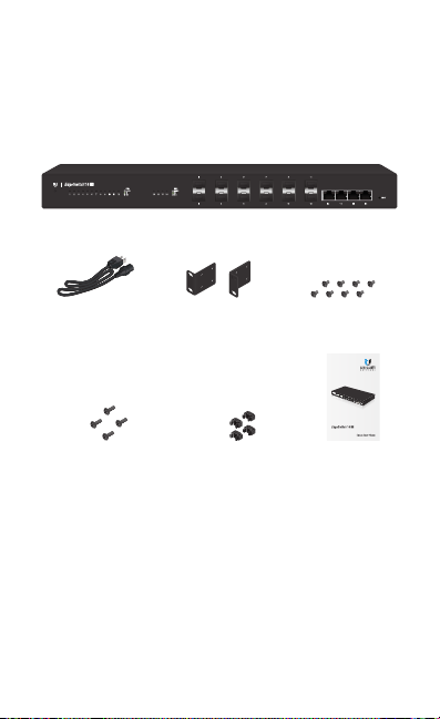
Package Contents
EdgeSwitch XG
Power Cord Rack-Mount Brackets
Mounting Screws
(#10-32 x 5/8", Qty. 4)
TERMS OF USE: All Ethernet cabling runs must use CAT6A (or above). It is the customer’s
responsibility to follow local country regulations, including operation within legal frequency
channels, output power, indoor cabling requirements, and Dynamic Frequency Selection
(DFS) requirements.
(Qty. 2)
Cage Nuts
(#10-32 x 5/8", Qty. 4)
Bracket Screws
(M4, Qty. 8)
10G 16-Port Managed
Aggregation Switch
Model: ES-16-XG
Quick Start
Guide
Installation Requirements
• Phillips screwdriver (for rack- or wall-mounting)
• Standard-sized, 19" wide rack with a minimum of 1U height
available (for rack-mounting)
• Use compatible fiber SFP+ modules with the appropriate
fiber optic cabling. For information about compatible fiber
SFP+ modules, visit: community.ubnt.com/edgemax
• For indoor applications, use Category 6A (or above) UTP
cabling approved for indoor use.
• For outdoor applications, shielded Category 6A (or above)
cabling should be used for all wired Ethernet connections
and should be grounded through the AC ground of the
power supply.
We recommend that you protect your networks from
harmful outdoor environments and destructive ESD events
with industrial-grade, shielded Ethernet cable from Ubiquiti
Networks. For more details, visit:
www.ubnt.com/toughcable
WARNING: To reduce the risk of fire or electric shock,
do not expose the switch to rain or moisture.
Note: Although the cabling can be located outdoors,
the EdgeSwitch XG itself should be housed inside a
protective enclosure.
Hardware Overview
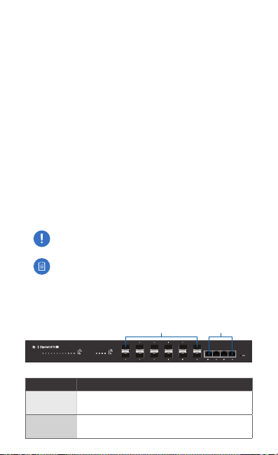
Front Panel Ports
Port Description
SFP+ 1-12
RJ45 13-16
Hot-swappable SFP+ ports support 1 Gbps
and 10 Gbps connections.
RJ45 ports support 1 Gbps and 10 Gbps
Ethernet connections.
SFP+ 1-12 RJ45 13-16
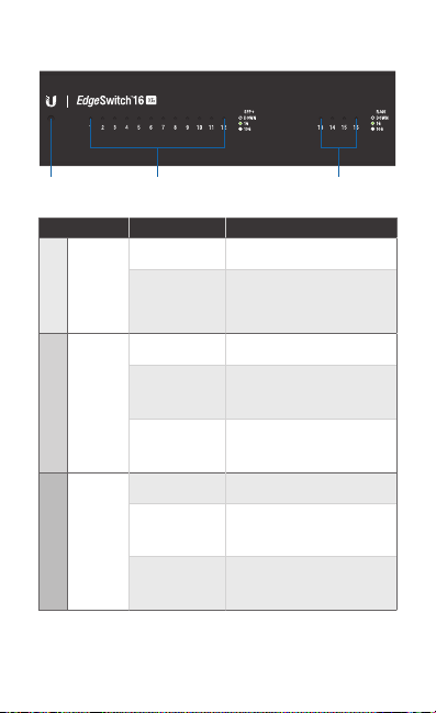
Front Panel LEDs
System
SFP+: Speed/Link/Act RJ45: Speed/Link/Act
LED State Status
White Ready for Use
System
SFP+ 1-12
RJ45 13-16
Blue
Off No Link
Speed/
Green
Link/
Act
White
Off No Link
Speed/
Green
Link/
Act
White
Bootup in Progress
Flashing Indicates Reset to
Factory Defaults
Link Established at 1Gbps
Flashing Indicates Activity
Link Established at 10Gbps
Flashing Indicates Activity
Link Established at 1Gbps
Flashing Indicates Activity
Link Established at 10Gbps
Flashing Indicates Activity
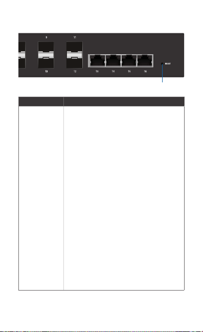
Front Panel Button
Button Description
Reset
There are two methods to reset the
EdgeSwitch XG to factory defaults:
Runtime Reset (Recommended)
The EdgeSwitch XG should be running
after bootup is complete, and the System
LED is white. Press and hold the Reset
button. The EdgeSwitch XG will reboot, and
the System LED becomesblue after three
seconds. Continue to hold the Reset button
for about 15seconds until the System LED
flashes blue for two seconds. This indicates
that the EdgeSwitch XG has reset to its
factorydefaults.
Power-on Reset
1. Disconnect the power from the
2. While connecting the power to the
Reset
EdgeSwitch XG.
EdgeSwitch XG, hold the Reset button
for about 15seconds until the System
LED flashes blue for two seconds. This
indicates that the EdgeSwitch XG has
reset to its factory defaults.
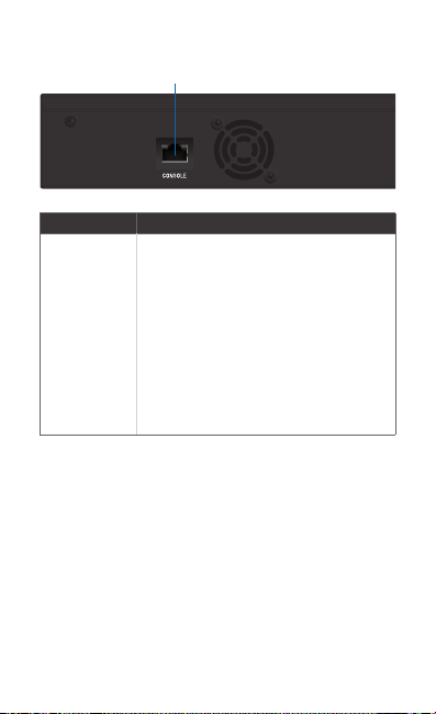
Back Panel Console Port
Console
Port Description
RJ45 serial console port for Command
Line Interface (CLI) management. Use an
RJ45-to-DB9, serial console cable, also
known as a rollover cable, to connect
the Console port to your computer. Then
Console
configure the following settings as needed:
• Baud rate 115200
• Data bits 8
• Parity NONE
• Stop bits 1
• Flow control NONE
*640-00227-03*
640-00227-03
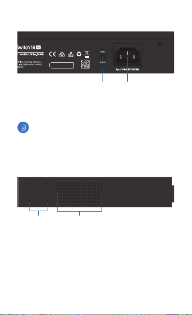
Back Panel Power
Power
DC Input
DC Input The 25VDC input can connect a redundant or
stand-alone DC power source (not included) with minimum
power: 56W, 25 to 16V, and 2.5 mm DC power inline connector.
Note: You can use the redundant DC power source as a
hot spare; if the internal AC/DC power supply no longer
provides power, then the EdgeSwitch XG will switch to
the DC power source without interrupting its operation.
Power Connect the included Power Cord to the Power port.
Side Panel
Bracket Mounting
Holes
Ventilation
Holes
Hardware Installation
The EdgeSwitch XG can be placed on a horizontal surface,
mounted on a wall, or mounted in a rack.
WARNING: FAILURE TO PROVIDE PROPER VENTILATION
MAY CAUSE FIRE HAZARD. KEEP AT LEAST 20 MM OF
CLEARANCE NEXT TO THE VENTILATION HOLES FOR
ADEQUATE AIRFLOW.
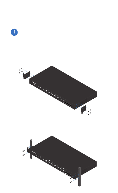
Mounting in a Rack (Optional)
1. Attach the Rack-Mount Brackets to the EdgeSwitch XG
using the eight Bracket Screws.
2. Attach the EdgeSwitch XG to the rack or wall using the four
Mounting Screws. (If the rack has square slots, then use the
Cage Nuts with the Mounting Screws.)
 Loading...