

Ubiquiti EP-R8 User Manual
Intelligent WISP Control
with FiberProtect
Model: EP-R8
™

Introduction
Introduction
Thank you for purchasing the Ubiquiti Networks® EdgePoint™
Router. This Quick Start Guide is designed to guide you through
installation and includes the warranty terms.
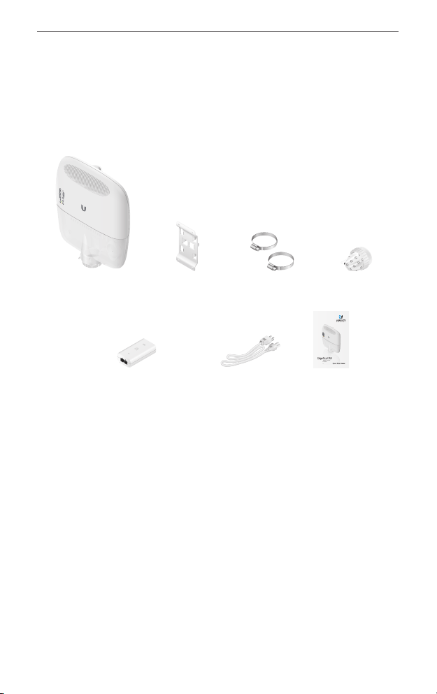
Package Contents
EdgePoint Router Wall-Mount
Bracket
Gigabit PoE (54V, 1.5A) with
Mounting Bracket
Metal Straps
(Qty. 2)
Power Cord Quick Start
Cable Sleeve
Intelligent WISP Control
™
with FiberProtect
Model: EP-R8
Guide
Installation Requirements
• 7 mm socket wrench
• S2 hex wrench
• Ground wire – min. 10 AWG (5 mm
safety precaution, ground the EdgePoint to a grounded mast,
pole, tower, or grounding bar.
• Shielded Category 5 (or above) cabling should be used for all
wired Ethernet connections and should be grounded through
the AC ground of the PoE.
• We recommend that you protect your networks from
harmful outdoor environments and destructive ESD events
with industrial-grade, shielded Ethernet cable from Ubiquiti
Networks. For more details, visit: www.ubnt.com/toughcable
TERMS OF USE: Shielded Ethernet cable and earth grounding must be used as conditions of product
warranty. TOUGHCable
follow local country regulations, including operation within legal frequency channels, output power,
and Dynamic Frequency Selection (DFS) requirements.
™
is designed for outdoor installations. It is the customer’s responsibility to
2
) and max. length: 1m. Asa
1
EdgePoint EP-R8 Quick Start Guide
Hardware Overview
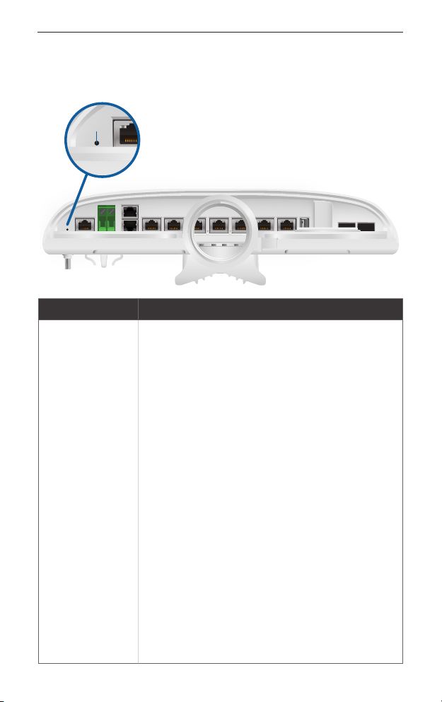
Bottom Panel Button
Reset
Button
Description
There are two methods to reset the EP-R8 to
factory defaults:
Runtime Reset (Recommended)
The EP-R8 should be running after bootup is
complete. Press and hold the Reset button
for about 10seconds until the eth7 or SFP2
LED starts flashing and then becomes solidly
lit (the SFP 2 LED is used if there is an SFP
module connected to the SFP 2 port). After
Reset
a few seconds, the LED will turn off, and the
EP-R8 will automatically reboot.
Power-on Reset
1. Disconnect power from the EP-R8.
2. Press and hold the Reset button while
connecting power to the EP-R8. Keep
holding the button until the eth7 or SFP 2
LED starts flashing and then stops flashing
after a few seconds (the SFP 2 LED is used
if there is an SFP module connected to the
SFP 2 port).
2
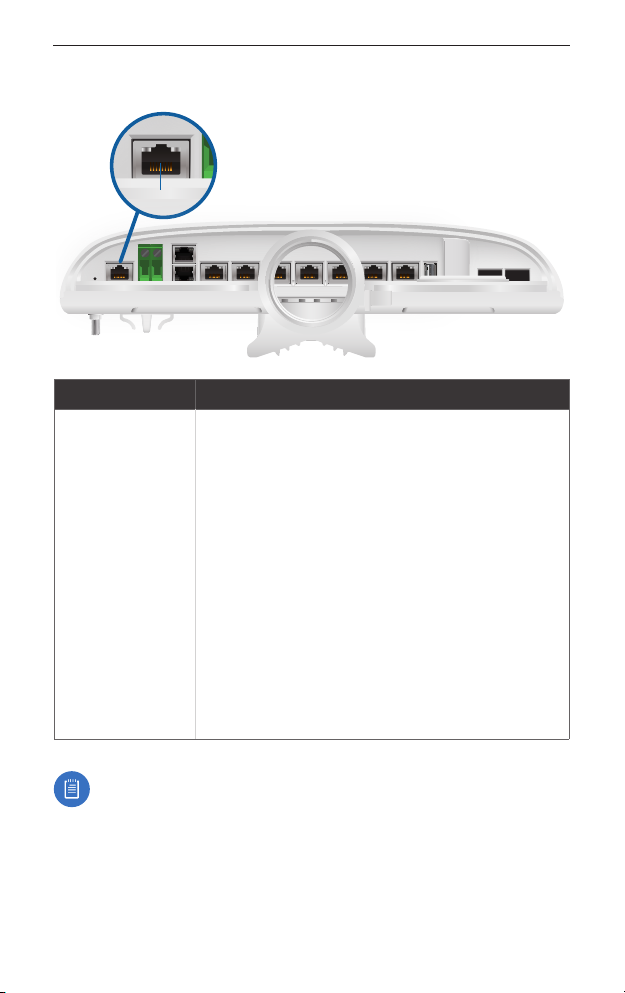
Bottom Panel Console Port
Console
Interface Description
RJ45 serial console port for Command
Line Interface (CLI) management. Use an
RJ45-to-DB9, serial console cable, also known
as a rollover cable, to connect the Console
port to your computer. (If your computer does
not have a DB9 port, then you will also need
a DB9 adapter.) Then configure the following
Console
settings as needed:
• Baud rate 115200
• Data bits 8
• Parity NONE
• Stop bits 1
• Flow control NONE
Hardware Overview
Note: Remove the protective plug from the Console port
before use.
3
EdgePoint EP-R8 Quick Start Guide
Power Options
Either the VDC or PoE input type is used at any one time. If both
are connected, only the input type with the highest voltage will be
used; the other can be used as a backup.
Both PoE inputs can be used at the same time. If there is a voltage
difference, the higher-voltage source will be used first. The voltage
from the initial source will drop as the load increases. When the
voltage drops to the same level as the lower-voltage source, then
the lower-voltage source will also start providing power.
Power Input Options
• 54VDC, 6A
• 54V, 1.5A on eth0 (PoE In)
• 54V, 1.5A on PoE In
The number of devices that can be powered depends on the
power consumption of the specific devices. Example: If you use
54VDC, 1.5A, then you have 81W. If the EdgePoint uses 40W, then
you have 41W for PoE output. Check product specifications for the
power consumption values to use in your calculations.
Power Output Options
• EdgePoint (required)
• Passive 54/24V, 4-Pair PoE on
eth1-eth2
• Passive 24V, 2-Pair PoE on
eth3-eth7
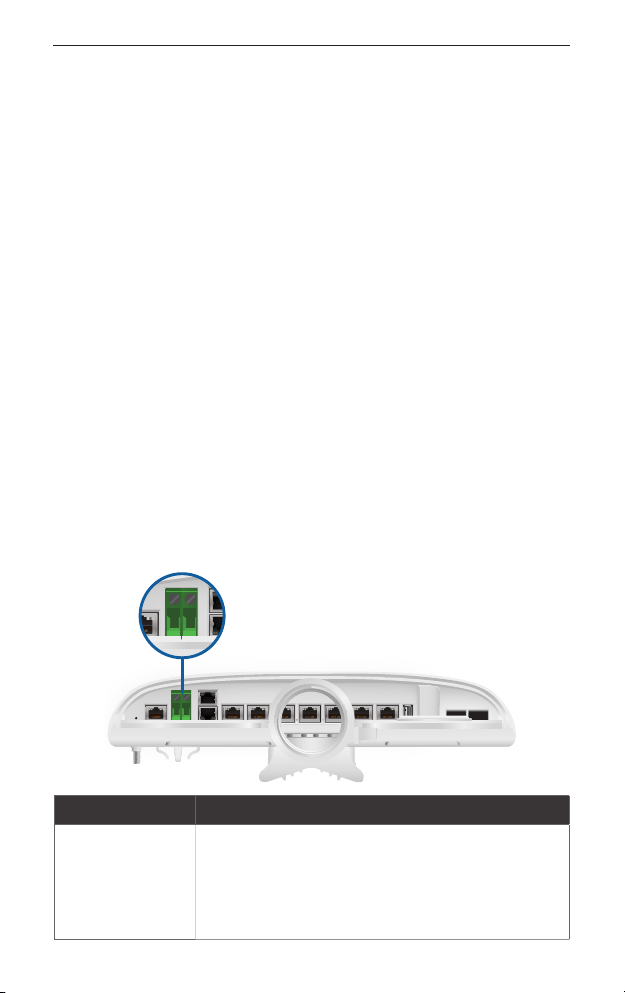
Bottom Panel DC Input
VDC
Interface Description
Terminal block connector uses auto-polarity
detection and accepts +42 to +56VDC, 6A
VDC In
4
input (including the Ubiquiti Networks
EdgePower™, model EP-54V-150W) to power
the EdgePoint and passive PoE output.
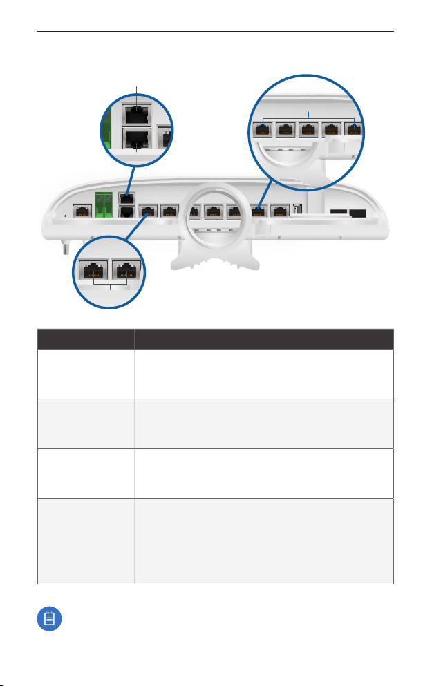
Bottom Panel RJ45 Ports
PoE In
eth0
eth1-2
Hardware Overview
eth3-7
Interface
Description
Accepts 54V, 1.5A PoE input from a secondary
PoE In
PoE adapter (not included) to power the
EdgePoint and passive PoE output.
Accepts data and 54V, 1.5A PoE input from
PoE In / eth0
the included Gigabit PoE Adapter to power the
EdgePoint and passive PoE output.
eth1-2
(54/24V
PoE Out)
RJ45 ports support 10/100/1000 Ethernet
connections and passive 54/24V, 4-pair PoE
output for airFiber® devices.
RJ45 ports support 10/100/1000 Ethernet
eth3-7
(24V PoE Out)
connections and passive 24V, 2-pair PoE
output for airMAX® devices.
RJ45 port eth6 or eth7 is active only if the
corresponding SFP port is empty.
Note: The USB port is reserved for future use.
5
EdgePoint EP-R8 Quick Start Guide
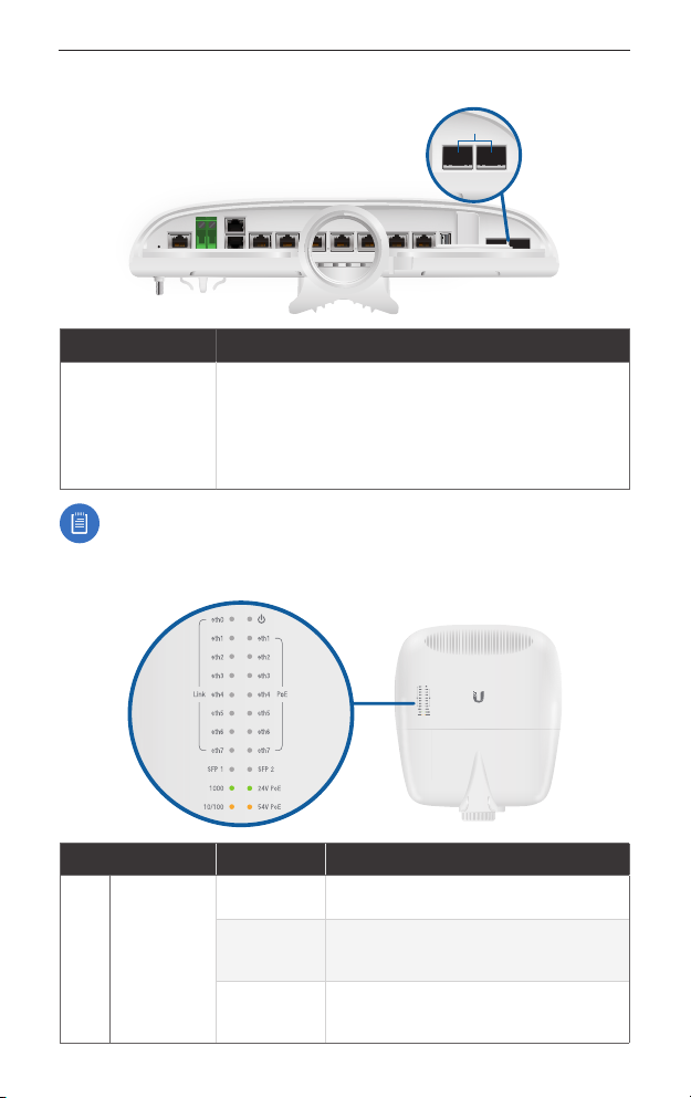
Bottom Panel SFP Ports
SFP 1-2
Interface
SFP 1-2
Note: For extreme temperatures, please use industrial-grade
fiber SFP modules.
Description
SFP ports are hot-swappable and support
100 Mbps or Gigabit fiber SFP modules. If an
SFP module is plugged in, then the SFP port
is active, and the corresponding RJ45 port is
deactivated.
Front Panel LEDs
LED State Status
Off No Link
Speed/
Link/Act
eth0
6
Amber
Green
10/100Mbps Link
Flashing Indicates Activity
1000Mbps (1 Gbps) Link
Flashing Indicates Activity

LED State Status
Hardware Overview
power
eth1-2
eth3-7
Speed/
Link/Act
PoE
Output
Speed/
Link/Act
PoE
Output
Green EdgePoint Powered On
Off No Link
Amber
Green
10/100Mbps Link
Flashing Indicates Activity
1000Mbps (1 Gbps) Link
Flashing Indicates Activity
Off No PoE
Amber 54V, 4-Pair Passive
Green 24V, 4-Pair Passive
Off No Link
Amber
Green
10/100Mbps Link
Flashing Indicates Activity
1000Mbps (1 Gbps) Link
Flashing Indicates Activity
Off No PoE
Green 24V, 2-Pair Passive
Link/Act
SFP 1-2
Speed/
Off No Link
Amber
Green
100Mbps Link
Flashing Indicates Activity
1000Mbps (1 Gbps) Link
Flashing Indicates Activity
7
EdgePoint EP-R8 Quick Start Guide
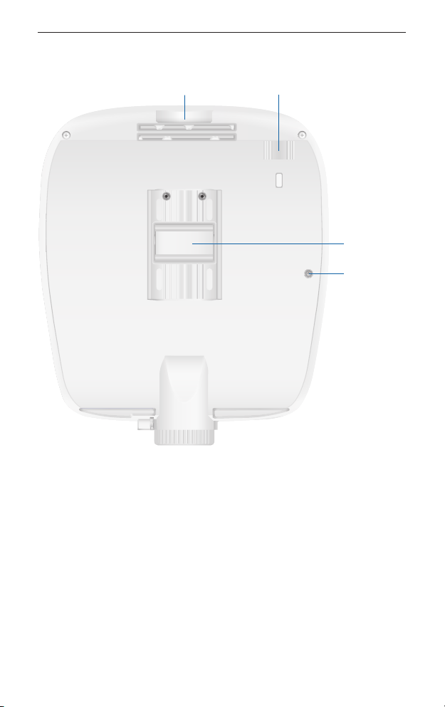
Back Panel
Lanyard Loop
PicoStation Slot
Pole-Mount
Bracket
Ground
Bonding Point
Lanyard Loop Used for temporary support during installation.
PicoStation®M2HP Slot Used for mounting an optional
PicoStationM2HP (not included) to the back of the EdgePoint. (You
can use the PicoStationM2HP for wireless management of the
EdgePoint.)
Pole-Mount Bracket Used for pole-mounting or in combination
with the included Wall-Mount Bracket for wall-mounting.
Ground Bonding Point Used to secure a ground wire (not
included).
8
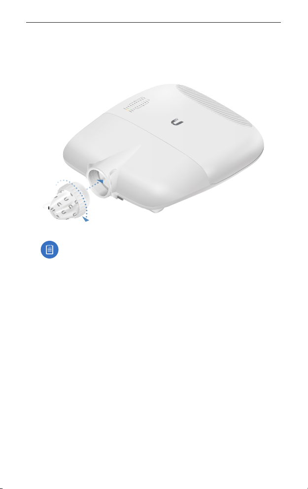
Attaching the Cable Sleeve
Attaching the Cable Sleeve
3. Insert and rotate the coupling to attach the Cable Sleeve to the
EdgePoint.
Note: You have two options for using a 2.0-inch NPT
(National Pipe Thread) male conduit (not included):
• Use the conduit instead of the CableSleeve.
• Use the conduit to extend the CableSleeve.
9
 Loading...