

Page 1
© 2007 Tyco Safety Products PAGE 1 of 10
801AP
17A-05-AP
4 8/07
EQUIPMENT:
PUBLICATION:
ISSUE No. & DATE:
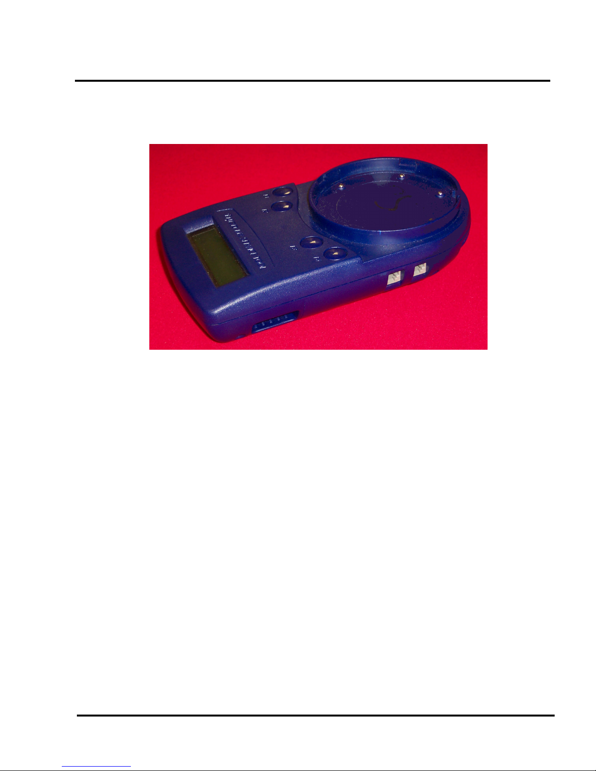
Fig. 1 801AP MX Service Too l
801AP MX SERVICE TOOL
USER INSTRUCTIONS
1. INTRODUCTION
The 801AP MX Service Tool is used to program the loop address
into MX addressable devices. (A Quick Functional Reference
Table is detailed on page 9).
The 801AP displays information and performs tests on devices.
It has a 32 character backlit LCD alphanumeric display, arranged
in 2 rows of 16 characters and four ‘softkeys’, F1, F2, F3 and F4.
(The display format is shown in Fig. 5).
Power for the 801AP is derived from 4 AA size nickel metal
hydride rechargeable batteries. It may be run from an unregulated
+12V dc input, ie, car cigarette lighter connection or 110/230V
ac mains adaptor, both of which will recharge the batteries as
well. The 801AP consists of the following:
• MX Service Tool
• Service Tool to ancillary connector lead
• 110 or 230V ac adaptor plus lead
• 4 x rechargeable AA size Nickel Metal Hydride
batteries
The 801AP is designed to be used as a desktop unit, clipped to a
trouser belt or be carried with a shoulder strap. The 801AP has
four external connections:
DC IN +12V From car cigarette lighter or
110/230V ac mains adaptor
AUX Ancillary connection port
PC PC connection port for use with
MX CONSYS (not yet available)
μP Internal micro-processor progr am
download port for use with PMS Program Management Software.
Detectors are programmed by placing the detector onto the
801AP and turning clockwise until fully engaged.
Ancillaries are programmed via the AUX port on the 801AP.
The ancillary programming cable consists of an RJ11
connector at one end and a custom moulded connector at the
other end.
2. TECHNICAL SPECIFICATION
2.1 MECHANICAL
Dimensions
HWD: 48 x 200 x 112mm
Weight
801AP Service Tool: 0.36kg
801AP Service Tool + batteries: 0.5kg
Materials
Top: FR ABS Dark Blue
Bottom: FR ABS Dark Blue
www.acornfiresecurity.com
www.acornfiresecurity.com
Page 2

801AP
17A-05-AP
4 8/07
PAGE 2 of 10
2.2 ELECTRICAL
Batteries: 4 x rechargeable AA size
Nickel Metal Hydride
Operating Time Up to 15 hours (dependent
(Batteries only) on battery charge and usage)
The ac adaptor is required when testing high current MX
addressable devices, including the SAM800/SAB800/
SAB801.
2.3 ENVIRONMENTAL
Operating Temperature: 0°C to +45°C
Storage Temperature: 0°C to +50°C
Relative Humidity: 90% (non-condensing)
Battery Disposal: No special considerations are
applicable in the UK at time of
writing. (Check with local
authorities).
2.4 EMC
The 801AP MX Service Tool meets the requirements of the
EU EMC Directive 89/336/EEC.
3. OPERATION
IMPORTANT:
FULLY CHARGE THE BATTERIES FOR 10
HOURS BEFORE USING FOR THE FIRST TIME
RECHARGE THE BATTERIES AS SOON AS
THE LOW BATTERY INDICATOR APPEARS.
DO NOT OPEN BATTERY LID WHILE THE UNIT
IS SWITCHED ON.
3.1 STARTING UP
3.1.1 INSTALLING BATTERIES
To install/change the batteries, proceed as follows:
a) Unscrew the two screws on the base of the 801AP,
using a cross-point screwdriver, holding the battery
compartment cover whilst removing it.
b) Insert the batteries ensuring correct polarity as sho wn
inside the battery compartment.
c) Replace the battery compartment cover and screw
down.
CAUTION:
ENSURE ONLY NICKEL METAL HYDRIDE
RECHARGEABLE BATTERIES ARE USED AND
FULLY CHARGED BEFORE USE.
3.1.2 CHARGING AND MAINS USE
The 801AP has its own built-in charging circuit, powered by
the mains adaptor. The batteries are boost-charged for 4-5
hours and reach full charge within 10 hours.
The 801AP can be powered from the mains supply using the
DC adaptor. If batteries are installed, this allows them to be
charged at the same time. For low battery indicator , see page 7.
3.2 PASSWORD PROTECTION
The 801AP MX Service Tool is switched ON/OFF by pressing
any button for more than 3 seconds. The following example
screen showing the software revision number , is displayed for
2 seconds when the Service Tool is switched on:
Note that the ‘E’ displayed stands for English version.
(appropriate letters are used for other languages). The Service
Tool then displays:
Note: The following information on Password
Protection is CRUCIAL to the operation of the
MX Service Tool.
Fig. 2 Battery Compartment
MX SERVICE TOOL
Rev 2.30.2012E
Password:
www.acornfiresecurity.com
www.acornfiresecurity.com
Page 3
801AP
17A-05-AP
4 8/07
© 2007 Tyco Safety Products PAGE 3 of 10
EQUIPMENT:
PUBLICATION:
ISSUE No. & DATE:
The Service Tool requires a 6-digit password to be entered.
The password is different for each service tool and will be
issued by the respective branch office.
The password uses only the digits 1 to 4, and may be entered
by pressing the corresponding buttons F1 to F4; eg, button F1
to enter 1, button F2 to enter 2, etc.
The user has 3 attempts to enter the correct code. On the 4th
attempt the following screen is displayed:
The user must telephone the branch office to get the correct
6-digit password at this point.
WARNING:
FAILURE TO ENTER THE CORRECT
PASSWORD AT THE FOURTH ATTEMPT
WILL RESULT IN THE SERVICE TOOL
SWITCHING OFF AND ALLOWING ONLY ONE
ATTEMPT ON SUBSEQUENT POWERING UP
OF THE UNIT.
The password has an expiry time associated with it.
The hours left indicates the actual usage (switched on) time
remaining.
CAUTION:
ONCE THE HOURS LEFT REACHES ZERO,
THE SERVICE TOOL BECOMES
INOPERABLE AND MUST BE RETURNED TO
THE BRANCH OFFICE.
When there is less than 50 hours, the expiry time appears. The
screen displays the expiry time in the form of ‘Hours Left’:
On successful entry of the password, the following screen is
displayed:
This is the start of the main menu options, which are
discussed further in para. 3.5.
Phone Base
Password:
Hours Left: 46
Password:
(example)
<-- Select -->
ADDRESS PROGRAM
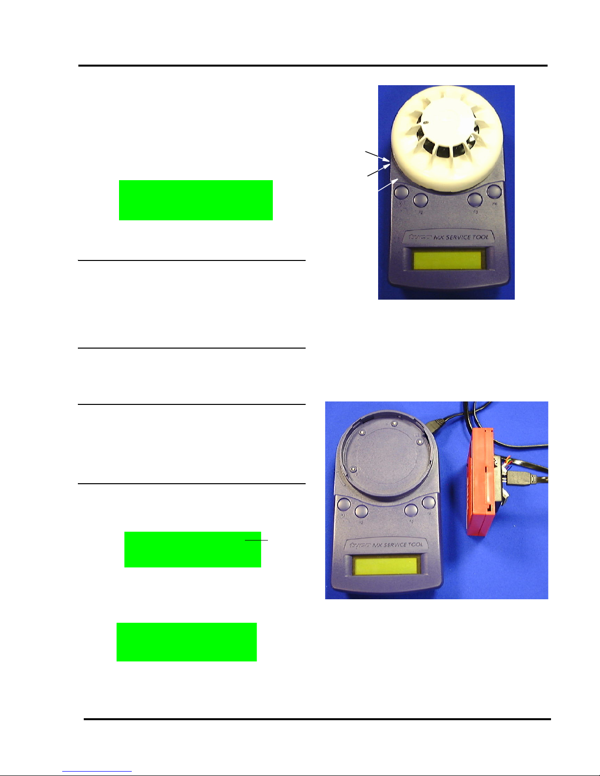
3.3 CONNECTING TO A DEVICE
Detectors are inserted as shown in Fig. 3. Use the marking on
the service tool (above F1 button) to align the detector. Place
detector in position 1 to engage and then twist clockwise to
position 2 to lock.
Ancillaries are connected to the ‘AUX’ socket using the
ancillary connection lead connector lead as shown in Fig. 4.
Note:
1) It is good practice to connect only a detector or
ancillary at any one time. However, the Ser vice
Tool is equipped with a port interlock feature.
When the ancillary lead is connected to the ‘Aux’
socket, communication with the detector will be
disabled. When the ancillar y lead is removed,
the detector will be able to communicate.
Fig. 3 Connecting a detector
POSITION 2
POSITION 1
MARKING
Fig. 4 Connecting to an ancillary
www.acornfiresecurity.com
www.acornfiresecurity.com
Page 4

801AP
17A-05-AP
4 8/07
PAGE 4 of 10
2) On older models of the 801AP Service Tool, the
detector had priority for communication. Newer
models of the 801AP, where the ancillary has
priority, can be identified by the C-tick mark on
the product identity label on the underside of the
tool (see Fig. 10 on Page 8)
3) The 801AP may be connected to an ancillary
device that is also connected to and powered
from the addressable loop. However, a ‘No
Response’ fault for that device may be
generated at the Control Panel under these
conditions.
WARNING:
SPECIAL CARE MUST BE TAKEN WHEN
CONNECTING TO A DEVICE ON THE
ADDRESSABLE LOOP TO PREVENT
UNWANTED A CTION IN O THER EQUIPMENT
EG, EXTINGUISHING SYSTEMS.
3.4 BUTTON OPERATION
The screen displays the start of the main menu as shown in
Fig. 5.
The main menu can always be identified by the word ‘Select’
between two arrows on the top line of the display. The
bottom line of the main menu displays the option.
The top line position of text is always shown in relation to the
F1-F4 buttons above. In the Main Menu:
• F1 scrolls left through the main menu options
• F2 or F3 select the menu option displayed
• F4 scrolls right through the main menu options
When an option is selected from the main menu, the display
uses the format shown in Fig. 6:
Fig. 5 First Display Screen of the main menu
The bottom line displays information to the user. The top
line displays the available options.
Note: The position of the options on the top line is
relative to the buttons.
Fig. 6 shows:
• F1 selecting ‘Back’
• F2 selecting ‘Write’
• F3 selecting ‘Dn’ (for down)
• F4 selecting ‘Up’
In some cases there may be fewer options available.
Fig. 7 shows:
• F1 selecting ‘Menu’
• F2 selecting ‘Write’
• F3 no action
• F4 clear used memory map
Fig. 6 Exa mple of Writing an address
Menu Write ClU
ADDRESS: 4
F1
F2
F3
F4
tyco MX SERVICE TOOL
Fig. 7 Exa mple of Re adi ng an address
www.acornfiresecurity.com
www.acornfiresecurity.com
Page 5

801AP
17A-05-AP
4 8/07
© 2007 Tyco Safety Products PAGE 5 of 10
EQUIPMENT:
PUBLICATION:
ISSUE No. & DATE:
In Fig. 8 pressing F1 selects the ‘Menu’, F2-F4 are redundant
here.
3.5 FUNCTIONALITY
ADDRESS PROGRAM
The main menu starts with ADDRESS PROGRAM. Press
buttons F2 or F3 to choose ‘Select’ and the address of the
device is displayed
(eg, address 4).
• Use ‘Write’ to program the device with a new
address
• ‘Menu’ to return to the main menu
• ClU to clear the memory map of used
addresses
Note: Whenever ‘Menu’ appears on the display, this
always returns to the main menu.
The Service Tool saves a memory map of the addresses that
have been programmed. To erase this, select menu and
choose Clear Used ‘ClU’.
If ‘Write’ is selected, the following screen is displayed:
• Use ‘Up’ to increase the address number
• ‘Dn’ to decrease it
Fig. 8 Example of Single Option
<-- Select -->
ADDRESS PROGRAM
Menu Write ClU
ADDRESS:4
Back Write Dn Up
ADD:4
• ‘Write’ to program the address displayed
• ‘Back’ to return to the previous screen
If ‘Write’ is selected then the following message will appear
for 2 seconds:
This is followed by:
Having programmed an address, the Service Tool moves to
the next sequential unused address.
If an address has already been used, the Service Tool
indicates:
If the user then decides to use a previously used address, the
following screen is displayed:
Press ‘Write’ and the Service Tool displays
‘PROGRAMMED OK’ briefly and then displays the next
available sequential address.
ANALOGUE VALUES
ANALOGUE VALUES displays the analogue values of the
attached device.
The above example shows a device with 2 channels, eg, an
Optical/Heat detector, where channel 1 is the optical value
and channel 2 is the heat value. Press ‘Menu’ to return to the
main menu.
Note:
1) Only displayed if channel 3 is used on a device.
2) These are the values that the device would
transmit to the control panel. T he v alues do
NOT
include any calibration or correction factors.
Back Write Dn Up
PROGRAMMED OK
Back Write Dn Up
ADD:5
Back Write Dn Up
ADD:6 USED
Back Write
ADD.USED:6
Menu
VAL:27 87
XX
CHANNEL 1 CHANNEL 2
SEE NOTE 1
www.acornfiresecurity.com
www.acornfiresecurity.com
Page 6

801AP
17A-05-AP
4 8/07
PAGE 6 of 10
MEASURE TEMP
This feature measures temperature in degrees Celsius and
degrees Fahrenheit, but is only available on detectors which
have a temperature sensing element, ie, Heat only, Optical
&
Heat and CO & Heat detectors. A typical display is shown
in b):
MEASURE CO LEVEL
For CO detectors only. Gives values for CO levels in the
measuring environment. Normal value is zero PPM (partsper-million).
TEST ALL
This option combines a test on the detector R1 and L2
terminals and tests the detector’s sensor circuitry for units
which have this facility.
• The Test R1 terminal tests the remote
indicator output.
• The Test L2 terminal tests the functional base
interface output.
• The Selftest tests the sensor input
circuitry. Completion of the Selftest may
require a maximum of 30 seconds.
Following the completion of all three tests, a test report is
displayed on the LCD. Each test can result in a PASS, FAIL
or NOT AVAILABLE report message.
To start a new test, select the TEST ALL menu to begin.
WAIT is displayed until all tests are completed.
When the tests are complete, the test results are reported on
three alternating displays:
b)
<-- Select -->
MEASURE CO LEVEL
Self Test is available on the following types of detectors:
• MX Ionisation.
• MX Optical + Heat (including 814P).
(Optical sensing element only).
• MX CO + Heat
(CO sensing element only).
• MX Flame.
Note: Self test is NOT available fo r the heat sensing
channels of these detectors.
DIRTINESS
Available for detectors with an optical sensing element
only. Indicates the contamination level of the optical
chamber. Compares the current optical analogue value as a
percentage where 0% would indicate that the analogue value
has not changed since manufacture, 100% would indicate
that the analogue value has risen to its maximum allowable
value (the point at which it would generate a fault).
At 80% or above, the detector should be replaced to avoid
the possibility of a fault occurring in the near future.
Note: Dirtiness can be displayed as a negative
number if the analogue value has fallen since
manufacture.
DEVICE TYPE ID
Device Type ID displays the unique value associated with
each addressable device Model No., eg, for Model No.
801PH - Type Value 10 is disp layed.
Type Value may be cross-referenced to Model No. by
referring to Table 2 on Page 10.
Menu TEST R1:
PASS
Menu TEST L2:
PASS
Menu SELFTEST:
PASS
Menu
Device Type: 10
www.acornfiresecurity.com
www.acornfiresecurity.com
Page 7

801AP
17A-05-AP
4 8/07
© 2007 Tyco Safety Products PAGE 7 of 10
EQUIPMENT:
PUBLICATION:
ISSUE No. & DATE:
DIGITAL INPUTS
This menu option displays the status of the digital inputs in
binary and as a decimal number between 0 to 255 for all
addressable devices.
The binary number is aligned with the least significant bit on
the right as indicated with a small ’
L’ character.
DIGITAL OUTPUTS
The user may set the Digital Output of the addressable device
by using the following function buttons, F2 to F4:
Flashing cursor denotes the digit to be set.
• - moves the cursor one position to the
right
• Tog - toggles between 0 and 1 for each digit
• ‘Set’ - prompts the 801AP to send an
instruction to the addressable device
• ‘Menu’ - to return to the main menu options
WARNING:
WHEN USING THE SERVICE TOOL WITH AN
ANCILLARY DEVICE CONNECTED TO THE
ADDRESSABLE LOOP, MAKE SAFE ANY
A TTACHED EQUIPMENT, eg, EXTINGUISHING,
PLANT SHUTDOWN etc. UNLESS IT IS BEING
USED SPECIFICALLY FOR TESTING THE
ATTACHED EQUIPMENT.
After ‘Set’ is selected, a message will appear asking for
confirmation of the action to send the data to the device,
as follows:
An LED test may be performed on addressable devices using
the digital output function. Move the cursor to the eigth bit
on the far-right and toggle this bit “1”. The LED should
illuminate red on all models”.
Menu
11100011
L
227
Menu Tog -- Set
00000000
L 0
CUSTOMER CODE
CAUTION:
THIS MENU OPTION CHANGES THE CUSTOMER
CODE OF THE SERVICE TOOL AND SHOULD
ONLY BE USED FOR DE-BUGGING PURPOSES.
IT SHOULD BE SET TO 254 NORMALLY.
Note:
1) Communication is only possible if the same
customer code is present in the addressable
device and the service tool.
2) The addressable device is manufactured with a
default code of 254. This is set in the de vice and
cannot be changed.
3.6 ADDITIONAL FUNCTIONS
DEVICE POLLING
In all operations that retrieve data from an attached device,
the 801AP polls the attached device at a pre-determined
interval. This interval is 2 seconds for the ADDRESS
PROGRAM function and 5 seconds for all other functions.
LOW BATTERY
This is indicated by a flashing symbol in the bottom right of
the LCD display.
The batteries must be charged using the mains adaptor with
its connecting lead plugged into the Service Tool dc input
socket.
LCD BACKLIGHT
The display can be temporarily illuminated by pressing any
two buttons simultaneously at any time.
AUTO POWER OFF
AUTO POWER OFF is designed to save battery life. If there
have been no button presses during the last 5 minutes, the
Service Tool automatically turns itself off.
www.acornfiresecurity.com
www.acornfiresecurity.com
Page 8

801AP
17A-05-AP
4 8/07
PAGE 8 of 10
CPU RESET
Note: This function is not normally used.
If the buttons or display are not responding correctly, the
Service Tool may be reset. This is done by pushing a small
jewellers type screwdriver into the pinhole on the bottom of
the Service Tool to actuate a switch.
When a CPU reset is carried out, the Service Tool will start
up as described in para 3.2 ‘Password Protection’.
INTRINSICALLY SAFE 800Ex DETECTORS
Intrinsically Safe 800Ex detectors can only be programmed
if an Ex dongle adaptor (supplied with the EXI800) is fitted
to the ‘AUX’ port of the 801AP Service Tool (see Fig. 9).
Note: On later models of the 801AP Service Tool, the
Ex dongle adaptor is not required for
programming Intrinsically Safe 800Ex
detectors. The applicable models of the 801AP
can be identified by the C-tick mark on the
product identification label on the underside of
the tool. See Fig. 10.
When using with Intrinsically Safe 800Ex devices, the
Service Tool must be used in a non hazardous safe area.
Fig. 9
Ex Dongle Adaptor
fitted to 801AP ‘ A UX’ port
3.7 PROGRAMMING LEAD
The new version of hardware (with the C-tick mark, on the
product identification label, Fig. 10) is compatible with
download lead 801PL PMS MX Programming Lead (S/C
No. 516.800.929) but is not compatible with earlier
download lead AVRISP-02 PMS MX Programming Lead (S/
C No. 516.800.928)
3.8 ACCESSORIES
3.8.1 ACCESSORY KIT (516.800.923)
Consisting of:
Carry case
Car lighter adaptor
Shoulder strap
3.8.2 SPARES
Spare ancillary lead: 516.800.922
Ancillary lead spare pins (bag of 10): 516.800.924
FOR MX ADDRESSABLE DEVICES
USES TYCO MX DIGITAL PROTOCOL
801AP - 516-800-918
MX SERVICE TOOL
Tyco Safety Products
N1156
DUNHAMS LANE
LETCHWORTH
SG6 1BE, UK
S/N FF.FF.FF.FF
Fig. 10
C-TICK MARK
www.acornfiresecurity.com
www.acornfiresecurity.com
Page 9

801AP
17A-05-AP
4 8/07
© 2007 Tyco Safety Products PAGE 9 of 10
EQUIPMENT:
PUBLICATION:
ISSUE No. & DATE:
MAIN MENU DISPLAY ACTIONS
‘Address Program’ Read/Writes the address of the connected addressable device
Reads the stored address map of used addresses
‘Analogue Values’ Displays the analogue values of the addressable device
‘Measure Temp.’ Measures temperature in degrees C and F (only available on detectors which have a
temperature sensing element)
‘Measure CO Level’ For CO detectors only. Gives values for CO levels in the measuring environment.
Normal value is zero PPM (parts-per-million)
‘Test All’ Performs:
a self test if the detector has such a facility
remote indicator output
functional base interface output
‘Dirtiness’
Indicates the contamination level of the optical chamber expressed as a percentage,
where 100% is the fault level
‘Device Type ID’ Displays the device type identification value
‘Digital Inputs’ Displays the status of the digital inputs in addressable devices
‘Digital Outputs’ Allows the user to set the digital outputs of the addressable device
‘Customer Code’ Not normally used, but it should be set to the same as the customer code in the device
Low Battery Indicates Low Battery by using a flashing symbol in the bottom right of the LCD display
CPU Reset Switch is accessed through a small hole at the rear of the unit near the label
LCD Backlight The display can be temporarily illuminated by pressing any two buttons simultaneously
Table 1: Functional Reference table
www.acornfiresecurity.com
www.acornfiresecurity.com
Page 10

801AP
17A-05-AP
4 8/07
PAGE 10 of 10
DESCRIPTION MARKET MODEL
TYPE
VALUE
Optical smoke
+ Heat
Europe 801PH 10
Marine 811PH 11
Australia 814PH 13
IS Baseefa 801PHEx 14
France 816PH 18
Ex ‘n’
Baseefa
811PHExn 11
Optical Smoke
Europe 813P 15
Australia 814P 17
France 816P 19
High sensitivity
optical smoke
Europe 801PS 17
Heat only
Europe/
France
801H/816H 20
Marine 811H 21
Australia 814H 23
IS Baseefa 801HEx 24
Ex ‘n’
Baseefa
811HExn 21
CO + heat
Europe 801CH 30
Marine 811CH 31
Australia 814CH 33
IS Baseefa 801CHEx 34
Ex ‘n’
Baseefa
811CHExn 31
Ion
Europe 801I 40
Australia 814I 43
Plug in – Flame
Detectors
World land 801F 65
IS 801FEx 66
Marine 811F 68
Marine IS 811FEx 69
CO + heat
+optical
Europe 801PC 70
Marine 811PC 71
Sounder
module
Europe SAM800 80
Sounder module
+ beacon
Europe SAB800 81
Sounder module
+ beacon
Europe SAB801 82
Mini-Input
Monitored
All MIM800 128
Callpoints
Indoor
UK/
Europe/
France
CP820 129
Outdoor
UK/
Europe/
France
CP830 130
Indoor Marine UK/Europe CP820M 131
Outdoor Marine UK/Europe CP830M 132
Ex ‘n’ Callpoint
EX ‘n’
Baseefa
CP830Exn 132
DIN Indoor Europe DIN820 133
DIN Outdoor Europe DIN830 134
Mini-Input
Monitored
Aus/NZ MIM801 138
Table 2: Type Values
JM/an
24
th
August 2007
DESCRIPTION MARKET MODEL
TYPE
VALUE
IS Call point IS Baseefa CP840Ex 139
Contact Input
Monitor
All/France CIM800 145
Detector Input
Module
All DIM800 146
IS Interface
module
IS Baseefa IF800Ex 147
Single Input/
Output module
All SIO800 148
Detector Driver
Module
All DDM800 149
Relay Interface
Module
All/France RIM800 161
Power Supply
Monitor
All APM800 162
Door Control
Module
Europe TSM800 165
Sounder/
Notification Mod
All SNM800 177
Loop Powered
Sounder
All LPS800 178
Aspirating
Detector
All VLC800 179
Extinguishing
Module
All LAV800 180
Beam Detector
Module
All BDM800 181
Loop Powered
Symphoni
Sounder
(Indoor)
UK/
Europe/
Middle
East/Asia
LPSY800-
R/W
183
Loop Powered
Symphoni
Sounder
(Outdoor)
UK/
Europe/
Middle
East/Asia
LPSY865 183
Loop Powered
Symphoni
AV
(Indoor)
UK/
Europe/
Middle
East/Asia
LPAV800-
R/W
184
Loop Powered
Symphoni
AV
(Outdoor)
UK/
Europe/
Middle
East/Asia
LPAV865 184
Dual Input
Output Module
All DIO800 193
Multi Input
Output Module
All/France MIO800 194
Table 2: Type Values
www.acornfiresecurity.com
www.acornfiresecurity.com
 Loading...