


Worldwide www.tyco-fire.com
Contacts
Model AV-1-300 Alarm Check Valve, 300 psi (20,7 bar) 2-1/2, 4, 6 & 8 Inch (DN65, DN100, DN150 & DN200) Vertical or Horizontal* Installation
General Description
The TYCO Model AV-1-300 Alarm Check Valves are divided seat ring, rubber-faced clapper, waterflow alarm check valves that are intended for use in wet pipe (automatic sprinkler) fire protection systems. They may be installed vertically or horizontally*, and they are designed to automatically actuate electric and/or hydraulic alarms when there is a steady flow of water into the system that is equivalent to the discharge rate of one or more sprinklers.
A separately ordered Model RC-1 Retard Chamber (Ref. Technical Data Sheet TFP920) is required for installations subject to variable pressures. It is used to help prevent false alarms associated with pressure variations in public water supplies.
The AV-1-300 Alarm Check Valve Trim includes pressure gauges to monitor system pressure conditions, a bypass check valve, a main drain valve, and an alarm test valve. The bypass check valve reduces the possibility of false alarms by permitting slow as well as small transient increases in water supply pressure to be passed through to the system without opening the waterway clapper.
NOTICE
The TYCO Model AV-1-300 Alarm Check Valves described herein must be installed and maintained in compliance with this document, as well as with the applicable standards of the National Fire Protection Association (NFPA), in addition to the standards of any authorities having jurisdiction. Failure to do so may impair the integrity of these devices.
The owner is responsible for maintaining their fire protection system and devices in proper operating condition. Contact the installing contractor or product manufacturer with any questions.
Technical
Data
Approvals
UL and C-UL Listed
FM Approved
Working Water Pressure Range
20 to 300 psi (1,4 to 20,7 bar)
Friction Loss
Refer to Graph A.
End Connections
Groove x Groove
Flange x Groove
Flange x Flange
Refer to Table A for size applicability
Weights
Refer to Table A.
Physical Characteristics
The body is ductile iron, the hand-hole cover is ductile iron, and the seat ring is bronze. The clapper for the 2-1/2 inch (DN65) valve size is stainless steel. The clapper for the larger valve sizes is ductile iron. All valve sizes utilize an EPDM clapper facing.
Flanged connections are available drilled per ANSI, ISO, AS, and JIS specifications as detailed in Table B.
Threaded port connections for the AV-1-300 Valves are available NPT threaded or threaded per ISO 7-1 as detailed in the Ordering Procedure section. Valves with NPT threaded ports will readily accept the trim arrangements detailed in Figures 4 through 6.
* 4, 6, and 8 inch (DN100, DN150, and DN200) valve sizes
For Fire Protection pressure rating, listing and approval information, contact
your Tyco Representative.
Page 1 of 20 |
SEPTEMBER 2014 |
TFP910 |

TFP910
Page 2 of 20
VALVE PARTS |
|
VALVE PARTS |
|
REPLACEMENT PARTS |
|||
NO. DESCRIPTION QTY. REF. |
NO. DESCRIPTION |
QTY. REF. |
NO. DESCRIPTION |
P/N |
|||
1 Valve Body . . . . . . . 1 |
NR |
12 Handhole Cover |
|
|
(a) Repair Parts Kit, |
|
|
2 Handhole Cover . . . 1 |
NR |
Hex Bolt, |
|
|
Includes 3 & 6 |
|
|
3 Handhole Cover |
|
2-1/2 Inch Valve, |
|
|
2-1/2 Inch Valve . . . . . . 92-200-1-216 |
||
Gasket . . . . . . . . . . 1 |
See (a) |
1/2-13 UNC-2A |
|
|
4 Inch Valve . . . . . . . . . 92-200-1-416 |
||
4 Seat Ring . . . . . . . . 1 |
NR |
x 1-1/4" Long . . . . . 4 |
CH |
6 Inch Valve . . . . . . . . . 92-200-1-620 |
|||
5 Clapper. . . . . . . . . . 1 |
See (b) |
4 Inch Valve, |
|
|
8 Inch Valve . . . . . . . . . 92-200-1-816 |
||
6 Clapper Facing . . . . 1 |
See (a) or (b) |
1/2-13 UNC-2A |
|
|
(b) Clapper Assembly, |
|
|
7 Clapper Washer . . . 1 |
See (b) |
x 1-3/4" Long . . . . . 4 |
CH |
Includes 5-9, 11 |
|
||
8 Lock Nut, |
|
6 Inch Valve, |
|
|
2-1/2 Inch Valve . . . . . . 92-200-1-218 |
||
2-1/2 Inch Valve . . . 1 |
See (b) |
1/2-13 UNC-2A |
|
|
Includes 5-11 |
|
|
Self-Locking Hex |
|
x 1-3/4" Long . . . . . 6 |
CH |
4 Inch Valve . . . . . . . . . 92-200-1-423 |
|||
Cap Screw, 4, 6, & 8 |
|
8 Inch Valve, |
|
|
6 Inch Valve . . . . . . . . . 92-200-1-623 |
||
Inch Valves . . . . . . . 1 |
See (b) |
3/4-10 UNC-2A |
|
|
8 Inch Valve . . . . . . . . . 92-200-1-823 |
||
9 Clapper Hinge Pin. . 1 |
See (b) |
x 2" Long. . . . . . . . . 6 |
CH |
NOTES: |
|
||
10 Clapper Hinge |
|
13 Clapper Hinge Pin |
|
|
|
||
Pin Bushing, |
|
Square Head Pipe |
|
|
1. F x F valve shown for reference; |
||
2-1/2 Inch Valve . . . 2 |
NR |
Plug, 3/8" NPT, |
|
|
|
components for G x G and F x G |
|
4, 6, & 8 Inch |
|
4, 6, & 8 Inch |
|
|
|
valves are shared. |
|
Valves . . . . . . . . . . . 4 NR |
Valves only . . . . . . . 1 |
CH |
2. |
NR: Not Replaceable |
|||
11 Clapper Spring . . . . 1 |
See (b) |
|
|
|
3. |
CH: Common Hardware |
|
|
|
|
|
|
|||
|
|
1 |
|
|
|
|
|
11 |
|
|
|
|
|
|
|
11 |
|
|
|
|
|
|
|
5 |
|
|
|
|
|
|
|
5 |
|
|
|
|
|
|
|
6 |
|
10 |
|
|
|
|
|
|
|
|
|
|
|
|
|
7 |
10 |
|
|
|
|
|
|
|
|
|
|
13 |
|
|
|
8 |
|
|
|
9 |
|
|
|
CLAPPER |
6 |
10 |
|
|
|
|
|
ASSEMBLY |
|
|
|
|
|||
2-1/2 INCH |
7 |
4 |
|
|
|
|
|
VALVE |
8 |
|
|
|
|
|
|
|
|
|
|
|
|
|
|
CLAPPER |
|
|
|
2 |
|
||
ASSEMBLY |
|
3 |
|
|
|||
|
|
|
|
|
|||
4, 6, & 8 INCH |
|
|
|
|
|
||
|
|
|
12 |
|
|||
VALVES |
|
|
|
|
|||
|
|
FIGURE 1 |
|
|
|
|
|
|
2-1/2, 4, 6 & 8 INCH (DN65, DN100, DN150 & DN200) |
|
|
||||
|
MODEL AV-1-300 ALARM CHECK VALVE ASSEMBLY |
|
|
||||
|
Nominal |
Groove x Groove, |
Flange x Groove, |
Flange x Flange, |
|
||
|
Valve Size, |
|
|||||
|
Lbs. |
|
Lbs. |
Lbs. |
|
|
|
|
Inches |
|
|
|
|||
|
(kg) |
|
(kg) |
(kg) |
|
|
|
|
(DN) |
|
|
|
|||
|
|
|
|
|
|
|
|
|
2-1/2 |
22 |
|
28 |
N/A |
|
|
|
(65) |
(10,0) |
|
(12,7) |
|
|
|
|
|
|
|
|
|||
|
4 |
38 |
|
47 |
57 |
|
|
|
(100) |
(17,2) |
|
(21,3) |
(25,9) |
|
|
|
6 |
58 |
|
70 |
84 |
|
|
|
(150) |
(26,3) |
|
(31,8) |
(38,1) |
|
|
|
8 |
102 |
|
120 |
149 |
|
|
|
(200) |
(46,3) |
|
(54,4) |
(67,6) |
|
|
TABLE A
AVAILABLE VALVE END CONNECTIONS AND VALVE WEIGHTS

TFP910
Page 3 of 20
FLOW RATE IN LITRES PER MINUTE (LPM)
(1 GPM = 3,785 LPM)
|
400 |
|
600 |
|
1000 |
|
|
2000 |
3000 |
|
5000 |
7000 |
|
10000 |
15000 |
|
|||
|
4.0 |
|
|
|
|
|
|
|
|
|
|
|
|
|
|
|
|
|
|
NOMINAL PRESSURE DROP IN POUNDS PER SQUARE INCH (PSI) |
3.0 |
|
|
|
|
|
|
|
|
|
|
|
|
|
|
|
|
0,20 |
NOMINAL PRESSURE DROP IN BAR (1 PSI = 0,06895 BAR) |
|
|
|
|
|
|
|
|
|
|
|
|
|
|
|
|
|
|||
2.0 |
|
|
|
|
(DN65) |
|
|
|
(DN100) |
|
|
|
(DN150) |
|
|
|
|
||
|
|
|
|
INCH |
|
|
INCH |
|
|
INCH |
|
|
(DN200) |
|
|||||
|
|
|
1/2 |
|
|
|
|
|
|
|
|
|
0,10 |
||||||
|
|
|
|
|
|
|
|
|
|
|
|
|
|||||||
|
- |
|
|
|
4 |
|
|
6 |
|
|
INCH |
0,09 |
|||||||
|
|
|
|
|
|
|
|
|
|
||||||||||
|
|
|
|
|
|
|
|
|
|
|
|
|
|||||||
|
2 |
|
|
|
|
|
|
|
|
|
|
|
|
|
|
0,08 |
|||
|
|
|
|
|
|
|
|
|
|
|
|
|
|
|
|
||||
1.0 |
|
|
|
|
|
|
|
|
|
|
|
|
|
8 |
|
0,07 |
|||
|
|
|
|
|
|
|
|
|
|
|
|
|
|
|
|||||
0.9 |
|
|
|
|
|
|
|
|
|
|
|
|
|
|
|
|
0,06 |
||
0.8 |
|
|
|
|
|
|
|
|
|
|
|
|
|
|
|
|
|||
|
|
|
|
|
|
|
|
|
|
|
|
|
|
|
|
|
|||
|
|
|
|
|
|
|
|
|
|
|
|
|
|
|
|
|
0,05 |
|
|
|
0.7 |
|
|
|
|
|
|
|
|
|
|
|
|
|
|
|
|
|
|
|
|
|
|
|
|
|
|
|
|
|
|
|
|
|
|
|
|
|
|
|
100 |
|
|
|
|
200 |
300 |
400 |
500 |
700 |
1000 |
|
|
2000 |
3000 |
4000 |
|
||
FLOW RATE IN GALLONS PER MINUTE (GPM)
GRAPH A
2-1/2, 4, 6 & 8 INCH (DN65, DN100, DN150 & DN200) MODEL AV-1-300 ALARM CHECK VALVE
NOMINAL PRESSURE LOSS VERSUS FLOW
|
|
|
|
|
|
|
|
Flange Drilling Speci cation |
|
|
|
|
|
|
|||||
Nominal |
|
|
|
|
|
Nominal Dimensions in Inches and (mm) |
|
|
|
|
|
||||||||
ANSI B16.1 |
|
ISO 2084 |
|
|
ISO 2084 |
|
|
JIS B 2210 |
|
AS 2129 |
|
||||||||
Valve |
|
|
|
|
|
|
|
||||||||||||
(Class 125) 1 |
|
|
(PN10) 2 |
|
|
|
(PN16) 3 |
|
|
|
(10K) |
|
(Table E) |
|
|||||
Size |
|
|
|
|
|
|
|
|
|
|
|||||||||
|
Dim. |
Dim. |
Qty. |
Dim. |
|
Dim. |
Qty. |
Dim. |
|
Dim. |
Qty. |
Dim. |
Dim. |
Qty. |
Dim. |
Dim. |
Qty. |
||
|
A |
B |
|
A |
|
B |
|
|
A |
|
B |
|
|
A |
B |
|
A |
B |
|
2-1/2 Inch |
5.50 |
0.75 |
4 |
|
|
|
|
|
5.71 |
|
0.71 |
4 |
|
5.51 |
0.75 |
4 |
5.00 |
0.71 |
4 |
(DN65) |
(139,7) |
(19,0) |
|
|
|
|
|
(145,0) |
|
(18,0) |
|
(140,0) |
(19,0) |
(127,0) |
(18,0) |
||||
|
|
|
USE |
|
|
|
|
|
|
|
|||||||||
4 Inch |
7.50 |
0.75 |
|
|
|
|
|
7.09 |
|
0.71 |
|
|
6.89 |
0.75 |
|
7.00 |
0.71 |
|
|
8 |
ISO 2084 |
|
|
|
8 |
|
8 |
8 |
|||||||||||
(DN100) |
(190,5) |
(19,0) |
|
|
(180,0) |
|
(18,0) |
|
(175,0) |
(19,0) |
(178,0) |
(18,0) |
|||||||
|
|
(PN16) |
|
|
|
|
|
|
|
||||||||||
|
|
|
|
|
|
|
|
|
|
|
|
|
|
|
|
|
|
||
6 Inch |
9.50 |
0.88 |
8 |
|
|
|
9.45 |
|
0.87 |
8 |
|
9.45 |
0.91 |
8 |
9.25 |
0.87 |
8 |
||
|
|
|
|
|
|
|
|||||||||||||
(DN150) |
(241,3) |
(22,2) |
|
|
|
|
|
(240,0) |
|
(22,0) |
|
(240,0) |
(23,0) |
(235,0) |
(22,0) |
||||
|
|
|
|
|
|
|
|
|
|
|
|||||||||
8 Inch |
11.75 |
0.88 |
8 |
11.61 |
|
0.87 |
8 |
|
11.61 |
|
0.87 |
12 |
|
11.42 |
0.91 |
12 |
11.50 |
0.87 |
8 |
(DN200) |
(298,5) |
(22,2) |
(295,0) |
|
(22,0) |
|
(295,0) |
|
(22,0) |
|
(290,0) |
(23,0) |
(292,0) |
(22,0) |
|||||
|
|
|
|
|
|
|
|
|
|||||||||||
Dim. A
Bolt Circle
Diameter
Dim. B
 Bolt Hole
Diameter
Qty. N
Number of
Bolt Holes
1Same drilling as for B16.5 (Class 150) and B16.42 (Class 250).
2Same drilling as for BS 4504 Section 3.2 (PN10) and DIN 2532 (PN10).
3Same drilling as for BS 4504 Section 3.2 (PN16) and DIN 2532 (PN16).
TABLE B
FLANGE DRILLING SPECIFICATIONS
TFP910
Page 4 of 20
Operation
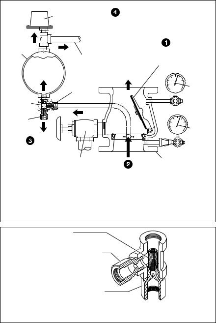
When the fire protection system is initially pressurized, water flows into the system until the water supply and system pressure become equalized, and the torsion Spring closes the Waterway Clapper in the Alarm Check Valve. Once the pressures stabilize, the Alarm Check Valve is in service and the centrally located groove in the Seat Ring is sealed. Consequently, with the Alarm Check Valve set for service, there is no flow through the alarm port to the alarm devices (i.e., water motor alarm and/or pressure alarm switch).
When there is a steady flow of water into the sprinkler system due to a sprinkler operation, the Waterway Clapper opens as shown in Figure 2. Water is then permitted to flow into the centrally located groove in the Seat Ring and out through the alarm port towards the Restriction Assembly (Figure 3). When the flow through the Inlet Restriction of the Restriction Assembly exceeds the flow through the Outlet Restriction, the Retard Chamber (where provided for systems with variable pressure), begins to fill.
Subsequently, the Water Motor Alarm and/or the pressure alarm switch will be actuated. The alarms will continue to be actuated as long as the Waterway Clapper remains open. Water in the alarm lines will automatically drain out through the 1/8 inch (3,2 mm) Drain Orifice in the Restriction Assembly (Figure 3) when the Waterway Clapper closes (due to a stop in the flow of water into the sprinkler system).
For variable pressure systems, slow as well as small transient increases in water supply pressure may continue to build up in the system (via the Bypass Check Valve) without opening the Waterway Clapper.
A transient surge in supply pressure that is sufficient only to open the Waterway Clapper momentarily will not cause a false alarm, and a portion of the increase in pressure will be trapped within the system, thus reducing the possibility of another opening. Any water in the alarm line is automatically drained, further reducing the possibility of a false alarm due to a successive transient surge in supply pressure.
Design
Criteria
In planning installation of the TYCO Model AV-1-300 Alarm Check Valves, consideration must be given to the disposal of the large quantities of water that may be associated with draining the system or performing a flow test.
|
WATERFLOW |
|
|
|
|
PRESSURE |
|
|
|
|
ALARM SWITCH |
|
|
|
|
ONCE RETARD |
|
||
|
CHAMBER OVERFLOWS, |
|
||
|
WATERFLOW PRESSURE |
|
||
|
ALARM SWITCH AND |
|
||
RETARD |
WATER MOTOR |
|
||
ALARM ACTUATE |
|
|||
CHAMBER |
UPON SPRINKLER |
|||
|
|
|||
|
WATERFLOW |
|
FLOW, WATERWAY |
|
|
TO WATER |
|
CLAPPER OPENS |
|
|
MOTOR ALARM |
WATERFLOW |
|
|
|
7/32" |
TO SYSTEM |
|
|
|
|
|
||
|
(5,6 mm) |
|
SYSTEM |
|
|
ORIFICE |
|
PRESSURE |
|
RESTRICTION |
INLET |
|
GAUGE |
|
|
|
|
||
ASSEMBLY |
|
|
|
|
1/8" |
|
|
|
|
(3,2 mm) |
|
|
|
|
ORIFICE |
|
|
SUPPLY |
|
OUTLET |
|
|
||
|
|
PRESSURE |
||
|
|
|
||
|
|
|
GAUGE |
|
WHEN FLOW THROUGH |
|
|
|
RESTRICTION ASSEMBLY |
|
|
|
INLET EXCEEDS OUTLET, |
MAIN |
|
ALARM |
RETARD CHAMBER |
DRAIN |
|
CHECK |
BEGINS TO FILL |
VALVE |
WATERFLOW |
VALVE |
THROUGH SEAT
RING GROOVE AND
ALARM PORT
FIGURE 2
2-1/2, 4, 6 & 8 INCH (DN65, DN100, DN150 & DN200) MODEL AV-1-300 ALARM CHECK VALVE OPERATION
SCREEN
INLET RESTRICTION
WITH 0.219" (5,6 mm)
ORIFICE
DRAIN RESTRICTION WITH 0.125" (3,2 mm) ORIFICE
FIGURE 3
RESTRICTION ASSEMBLY (Provided with Alarm Check Valve Trim)
Valves installed in the vertical position must have the flow going up. Valves installed in the horizontal position must be positioned so that the drain connection points down.
The sprinkler system designer must be aware that the configuration of the piping network and its tendency to trap pockets of air (such as in the case of a peaked-roof gridded system) can affect the performance of the alarm system. Although a slight amount of trapped air is desirable to prevent significant pressure increases due to thermally induced expansion of the water, a large quantity of trapped air in a system may result in the possibility of an intermittent alarm.
The possibility of an intermittent alarm condition is a consequence of the fact that the flow out of the system through the test valve or a single sprinkler is very small relative to the flow that can be passed through the valve. This difference increases with valve size. If the system were free of trapped air, flow in would equal flow out and the Waterway Clapper would always stabilize at some open position (as needed to accommodate the required flow). With trapped air in the system, however, the Waterway Clapper first opens wider since the system initially demands greater flow until the air pockets are compressed (back to nearly the supply pressure), and then it will tend to return closer

to the Seat Ring. If the volume of the air pockets is excessive, flow into the system can be momentarily reduced to nearly zero (once the air pockets are compressed) and the Waterway Clapper may close, causing flow to the alarms to be shutoff.
After the Waterway Clapper has closed, sufficient water must flow out of the system before the Waterway Clapper will again open. A repetition of the above described condition is termed an intermittent alarm.
Using a vent (which can also serve as an end-of-line Inspector’s Test Connection) piped from the top of a cross main or end of a branch line at the point most remote from the alarm valve, and filling the system slowly in accordance with the steps described in the Setting Procedure section, can prevent an excessive amount of air from being trapped.
Installation
NOTICE
Proper operation of the TYCO Model AV-1-300 Alarm Check Valves depends upon the trim described in this data sheet installed in accordance with the following instructions. Failure to follow the appropriate trim installation instructions may prevent the device from functioning properly as well as void listings/approvals and the manufacturer’s warranties.
The Alarm Check Valves must be installed in readily visible and accessible locations.
It is recommended that provision be made for viewing the alarm line drain water by locating the main drain outlet in a readily visible area.
Wet pipe fire protection systems must be maintained at a minimum temperature of 40°F (4°C).
Step 1. Trim the Alarm Check Valve in accordance with Figure 4, 5, or 6, as applicable. Apply pipe-thread sealant sparingly to male threads only.
Step 2. The Alarm Vent Trim illustrated in Figure 8 must be installed if a water motor alarm is not to be used.
Step 3. Plug unused alarm connections.
Step 4. Suitable provision must be made for disposal of alarm line and system drainage water. Drainage water must be directed so that it will not cause damage or result in dangerous conditions.
Step 5. The alarm line drain must be arranged so that there will be no danger of freezing.
Step 6. The check valve in the externally mounted bypass around the Waterway Clapper must be installed with its arrow pointed up, and the drain check valve must be installed with its arrow pointing towards the drain.
Step 7. It is recommended that a vent connection (which may also be used as an end-of-line Inspector’s Test Connection), be piped from a cross main or branch line at the point most remote from the alarm valve. The vent line should be connected to the top of a cross main or to the end of a branch line and be located at the highest level of a multi-level installation.
The vent connection can be used to bleed-off excessive air from the system, and therefore, minimize the possibility of a false alarm due to a transient surge in supply pressure. The contraction/expansion associated with an excessive amount of trapped air could also cause the Waterway Clapper to cycle open and shut during an inspector’s test or during a discharge by a single sprinkler.
Setting Procedure
Steps 1 through 11 are to be performed when initially setting the Model AV-1- 300 Alarm Check Valve or after system operation due to a fire.
NOTICE
Filling the system with water will result in operation of the associated alarms. Consequently, notification must first be given to the owner and fire department, central station, or other signal station to which the alarms are connected.
Notify the proper authorities and all personnel who may be affected that an alarm test is to be performed.
After placing a fire protection system in service, notify the proper authorities and advise those responsible for monitoring proprietary and/or central station alarms.
Step 1. Open the 1/4 inch Gauge Test Valves for the Supply and System Pressure Gauges.
Step 2. Check to see that the Handhole Cover bolts are tight. If not, cross-tighten them.
Step 3. Close the Alarm Test Valve.
Step 4. Open the remote cross main or branch line vent connection. (Refer to Step 7 in the Installation section.)
Step 5. Slowly open the main control valve until the sound of flowing water just begins and then open the valve one more turn.
TFP910
Page 5 of 20
Step 6. Close the remote branchline vent connection after the discharge of aerated water ceases, and the outlet has flowed full for at least 15 seconds.
Step 7. Fully open the main control valve.
Step 8. Open the end-of-line Inspector’s Test Connection (or Alarm Test Valve, if acceptable to the authority having jurisdiction) and verify that the system alarms operate.
Step 9. Close the end-of-line Inspector’s Test Connection (or Alarm Test Valve).
Step 10. Verify that water ceases to flow from the alarm line drain. If water continues to flow, follow the corrective procedure described in the Care and Maintenance section.
The Restriction Assembly has a 1/8 inch (3,2 mm) diameter drain orifice. Sufficient time must be allowed for drainage of the Retard Chamber and the piping to the water motor alarm.
Step 11. After verification that the flow of water out of the alarm line drain has stopped, the alarm valve is set and is ready for service.

TFP910
Page 6 of 20
|
NO. DESCRIPTION |
|
QTY. |
P/N |
|
|
|
NO. DESCRIPTION |
QTY. |
P/N |
|
|
|||
|
1 |
300 psi/ 2000 kPa |
|
|
|
|
|
|
17 |
1/2" x 1/4" x 1/2" Tee. . . . 2 |
CH |
|
|
||
|
|
Water Pressure Gauge |
. . 2 |
92-343-1-005 |
18 |
1/2" x 1/2" x 3/4" Tee. . . . 1 |
CH |
|
|
||||||
|
2 |
1/4" Gauge Test Valve |
. . 2 |
46-005-1-002 |
19 |
1-1/4" x 1-1/4" x 1/2" Tee 1 |
CH |
|
|
||||||
|
3 |
1/2" Swing Check Valve . 2 |
46-049-1-004 |
20 |
1/4" x 1" Nipple . . . . . . . . 2 |
CH |
|
|
|||||||
|
4 |
1/2" Globe Valve . . . . . . . 1 |
46-047-1-004 |
21 |
1/4" x 2-1/2" Nipple. . . . . 1 |
CH |
|
|
|||||||
|
5 |
1/2" Y-Strainer . . . . . . . . . 1 |
52-353-1-005 |
22 |
1/2" x 1-1/2" Nipple. . . . . 7 |
CH |
|
|
|||||||
|
6 |
Restriction Assembly. . . . 1 |
92-210-2-005 |
23 |
1/2" x 2" Nipple . . . . . . . . 2 |
CH |
|
|
|||||||
|
7 |
1-1/4" Angle Valve. . . . . . 1 |
46-048-1-007 |
24 |
1/2" x 2-1/2" Nipple. . . . . 1 |
CH |
|
|
|||||||
|
8 |
External By-Pass Tube . . 1 |
92-304-1-017 |
25 |
1/2" x 3" Nipple . . . . . . . . 1 |
CH |
|
|
|||||||
|
9 |
Alarm Test Tube |
. . . . . . . 1 |
92-304-1-047 |
26 |
1/2" x 4" Nipple . . . . . . . . 1 |
CH |
|
|
||||||
|
10 |
1/2" NPT x 1/2" Tube |
|
|
|
|
|
|
27 |
1/2" x 6" Nipple . . . . . . . . 1 |
CH |
|
|
||
|
11 |
Connector . . . . . . . . . . . . 2 |
CH |
|
|
|
28 |
1-1/4" x 2-1/2" Nipple. . . . 1 |
CH |
|
|
||||
|
1/2" NPT x 5/8" Tube |
|
|
|
|
|
|
29 |
1-1/4" x 3-1/2" Nipple. . . . 1 |
CH |
|
|
|||
|
|
Connector . . . . . . . . . . . . 2 CH |
|
|
|
|
|
|
|
|
|
||||
|
12 |
1/4" Plug . . . . . . . . . . . . . 2 |
CH |
|
|
|
NOTES: |
|
|
|
|
||||
|
13 |
1/2" Union . . . . . . . . . . . . 1 |
CH |
|
|
|
|
|
|
|
|||||
|
14 |
1/4" 90° Elbow. . . . . . . . . 1 |
CH |
|
|
|
1. All Fittings and Nipples are galvanized |
|
|
||||||
|
15 |
1/2" 90° Elbow. . . . . . . . . 1 |
CH |
|
|
|
(Standard Order). |
|
|
|
|
||||
|
16 |
1/2" Tee . . . . . . . . . . . . . . 2 |
CH |
|
|
|
2. CH: Common Hardware. |
|
|
|
|||||
|
|
|
|
|
|
|
|
|
|
|
|
|
|||
1/2 INCH NPT |
|
|
|
|
|
|
|
|
|
|
|
|
|
|
|
CONNECTION |
|
|
|
|
|
|
|
|
|
|
|
|
|
|
|
FOR WATERFLOW |
|
|
|
|
|
|
|
|
|
|
|
|
|
|
|
PRESSURE ALARM |
|
|
|
|
|
|
|
|
|
|
|
|
|
|
|
SWITCH |
|
|
|
|
|
|
|
|
|
|
|
|
|
|
|
|
|
|
3/4 INCH NPT |
|
|
|
|
|
|
|
|
|
|||
LOCATION |
|
CONNECTION FOR |
|
|
EXTERNAL |
|
|
|
|
||||||
FOR OPTIONAL |
|
|
WATER MOTOR |
|
|
|
|
|
|
||||||
|
|
|
|
|
BY-PASS |
|
|
|
|
||||||
ELECTRICALLY |
|
|
ALARM |
|
|
|
|
|
|
|
|
||||
|
|
|
|
|
|
TUBE |
|
|
ALARM |
|
|||||
SUPERVISED |
|
|
|
|
|
|
|
|
|
|
|
|
|||
|
|
|
|
|
|
|
|
|
|
8 |
|
TEST TUBE |
|
||
N.O. ALARM |
|
|
1/2 INCH NPT |
|
|
ALARM |
9 |
|
|||||||
|
|
|
|
11 3 |
|
|
|
||||||||
CONTROL |
|
|
CONNECTION |
|
TEST VALVE |
10 |
|
|
|
||||||
VALVE |
|
FOR WATERFLOW |
|
(NORMALLY |
|
23 |
|
|
1 |
||||||
|
|
PRESSURE ALARM |
CLOSED) |
11 |
|
|
|
SYSTEM |
|||||||
|
|
|
|
|
PRESSURE |
||||||||||
|
|
|
SWITCH |
|
|
|
|
|
|
|
|
||||
MODEL RC-1 |
|
|
|
|
|
|
|
|
20 |
|
GAUGE |
||||
|
|
|
|
|
|
|
|
|
|
|
|
|
|||
RETARD |
|
|
|
|
|
3/4 INCH NPT |
|
|
|
17 |
|
12 |
|||
CHAMBER |
|
|
18 |
|
CONNECTION FOR |
|
25 |
|
|
1 |
|||||
|
|
|
|
|
WATER MOTOR |
|
16 |
|
2 |
SUPPLY |
|||||
|
|
|
|
|
|
|
|
||||||||
ORDERED |
|
|
|
|
|
ALARM |
|
10 |
22 |
|
|
PRESSURE |
|||
|
|
|
|
|
|
|
|
|
|
4 |
|
|
|
12 GAUGE |
|
SEPARATELY |
LOCATION |
|
|
|
|
|
|
|
|
23 |
|
14 |
|
||
(FOR VARIABLE |
FOR OPTIONAL |
|
|
|
5 |
|
|
|
16 |
|
|
20 |
21 |
|
|
PRESSURE |
ELECTRICALLY |
|
|
22 |
|
|
|
|
|
17 |
2 |
||||
|
|
|
|
|
27 |
24 |
|
|
|
||||||
SYSTEMS) |
SUPERVISED |
22 |
|
|
|
|
|
|
26 |
|
|||||
|
|
|
|
|
|
|
|
|
|
|
|
||||
|
N.O. ALARM |
|
|
|
|
|
|
|
|
|
|
|
|
||
|
|
|
|
|
|
|
|
|
|
MODEL AV-1 |
|
|
|||
|
CONTROL |
6 |
|
|
|
|
|
|
|
|
|
|
|||
|
|
VALVE |
|
|
|
MAIN |
|
|
|
|
ALARM VALVE, |
|
|
||
|
|
|
|
|
|
|
|
|
28 |
2-1/2 INCH (DN65) |
|
||||
|
|
|
|
|
DRAIN VALVE |
|
|
GROOVE x GROOVE |
|
||||||
|
RESTRICTION |
22 |
|
(NORMALLY |
|
|
7 |
|
SHOWN |
|
|
||||
|
|
|
|
CLOSED) |
|
|
|
|
|
|
|
|
|||
|
ASSEMBLY, |
|
|
|
|
|
|
|
|
29 |
|
|
|
|
|
|
SEE FIGURE 3 |
|
|
|
|
|
|
|
|
19 |
|
|
|
|
|
|
|
|
|
|
|
|
|
|
|
|
|
|
|
|
|
|
|
|
15 |
22 |
13 |
22 |
3 |
22 |
1-1/4 INCH NPT |
|
|
|
|||
|
|
|
CONNECTION |
|
|
|
|||||||||
|
|
|
|
|
|
|
|
|
|
|
|
|
|
||
TO DRAIN
FIGURE 4 (1 OF 3)
VERTICAL CLOSED DRAIN TRIM — STANDARD ORDER
FOR 2-1/2 INCH (DN65) MODEL AV-1-300 ALARM CHECK VALVES (P/N 52-204-4-950)
 Loading...