


BFV-300
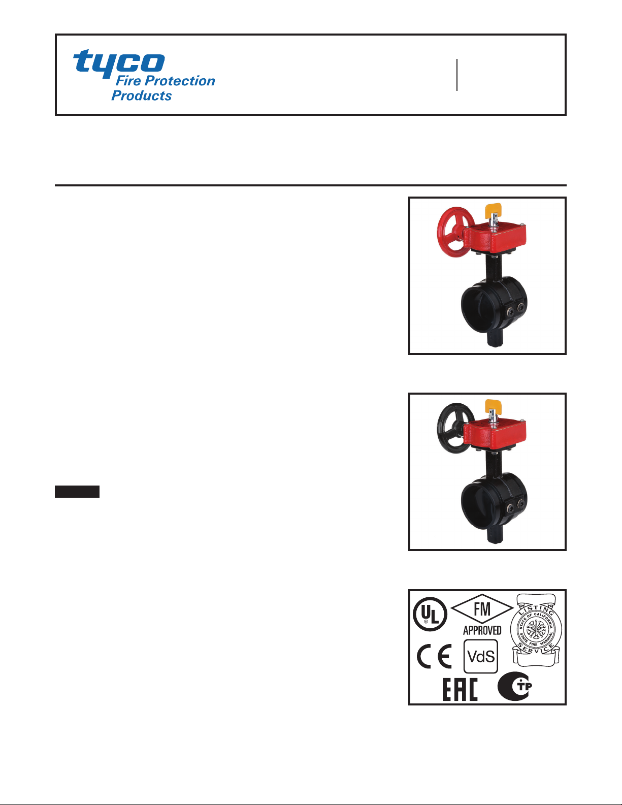
Model BFV-300/BFV-300C
Butterfly Valve
Grooved End
Page 1 of 8 JUNE 2016 TFP1511
Worldwide
Contacts
www.tyco-fire.com
Technical
Data
Approvals
UL Listed
FM Approved
CE Certified
VdS Approved
Russian Fire Certificate
CNPP R1 Li sted – APSAD
Listed by California State Fire Marshall
Refer to Tables A, B and C for applicability.
All laboratory listings and approvals are for
indoor and outdoor use.
Sizes
2 – 12 Inch ( DN50 – DN30 0)
UL/FM Maximum Working Pressure
2 – 8 Inch (D N50 – DN200 ) . . . . 300 psi ( 20,7 bar)
10 – 12 I nch (D N250 – DN30 0) . . 175 psi (12,1 bar)
VdS Maximum Working Pressure
2 – 8 Inch (D N50 – DN200 ) . . . . 300 psi ( 20,7 bar)
10 Inch (DN250) . . . . . . . . . . . 232 psi (16,0 bar)
12 Inch (DN300 ) . . . . . . . . . . . . 175 psi (12,1 bar)
Maximum Working Temperature
212°F (100°C) in accordance with UL 1091
Materials of Construction
Body . . . . . . . . . . . . . . . . . . . . . . . . . Ductile Iron
Body Coating . . . . . . . . . . . RILSAN PA11 Black
Disc . . . . . . . . . . . . . . . . . . . . . . . . . . Ductile Iron
Disc Seal ...............EPDM Encapsulated
Upper & Lower Stem . . . . . . . . . . Stainless Steel
Handwheel . . . . . . . . . . . . . . . . . . . . Ductile Iron
(BFV-300 red painted; BFV-300C black painted)
Actuato r, 2 – 6 Inch (D N50 – DN150) :
• IP 65, bronze traveling nut gea rbox, ductile
iron housing
Actuato r, 8 – 12 In ch (DN 200 – DN30 0):
• IP 65, brass segmented gearbox, ductile iron
housing
Tapping Bosses
Two factory-plugged NPT threaded tapping
bosses in the valve body are located on the
up- and downstream sides of the disc for
connection to valve trim. Tapping boss
sizes:
2 – 3 inch (D N50 – DN80 ) .............3/8 NPT
4 – 12 inch ( DN100 – DN30 0) ..........1/2 NPT
100% Silicone Free
Model BFV-300/BFV-300C Butterfly Valves
are produced and assembled using no
silicone lubricants in any form (like grease
or aerosol spray) and are suitable for paint
or oxygen applications.
General
Description
The TYCO Models BFV-300 and BFV-
300C Grooved End Butterfly Valves
are indicating type valves designed for
use in fire protection systems where
a visual indication of open or closed
valve condition is required. They are
used, for example, as system, sec-
tional and pump water control valves.
They have grooved inlet and outlet con-
nections that are suitable for use with
grooved end pipe couplings listed or
approved for fire protection systems.
For applications requiring supervi-
sion of the open or closed state of the
valve, the Gear Operators for the Model
BFV-300/BFV-300C Butterfly Valves
feature two sets of factory installed
internal switches each having SPDT
contacts ( Ref. Figure 3). The super-
visory switches transfer their electri-
cal contacts when there is movement
from the open or closed disc position
during the first two revolutions of the
handwheel.
NOTICE
The Model BFV-300/BFV-300C
Grooved End Butterfly Valves described
herein must be installed and maintained
in compliance with this document, as
well as with the applicable standards
of the National Fire Protection Asso-
ciation, in addition to the standards of
any other authorities having jurisdiction.
Failure to do so may impair the perfor-
mance of these devices.
The owner is responsible for main-
taining their fire protection system
and devices in proper operating con-
dition. Contact the installing contrac-
tor or product manufacturer with any
questions.
Control Valve Seat Leakage
Class IEC 60534-4
CLASS VI (Type C) Control Valve Seat
Leakage according to ANSI/FCI
70-2-2006 (ASME B16.104)
MODEL BFV-300
WITH OPEN SUPERVISORY
SWITCHES
MODEL BFV-300C
WITH CLOSED SUPERVISORY
SWITCHES
TF P1511
Page 2 of 8
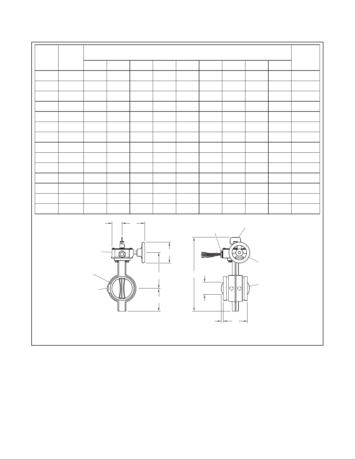
Nominal
Valve Size
Inches
(DN)
Pipe
OD
Inches
(mm)
Nominal Dimensions
Inches
(mm)
Weight
Lbs.
(kg)
A B C D E F G H J
2
(DN50)
2.37
(60,3)
3.8
(96,4)
10.6 3
(270)
2.85
(72,5)
4.90
(124, 5)
4.92
(125)
4.28
(108 ,6)
1.9 9
(50,5)
0 0
10.8
(4,9)
2-1/ 2
(DN65)
2.88
(73,0)
3.8
(96,4)
11.72
(297, 8 )
3.35
(85)
5.5
(139,8 )
4.92
(125)
4.28
(108 ,6)
1.9 9
(50,5)
0 0
13.0
(5,9)
—
(DN65)
3
76 ,1
3.8
(96,4)
11.72
(297, 8 )
3.35
(85)
5.5
(139,8 )
4.92
(125)
4.28
(108 ,6
1.9 9
(50,5)
0 0
13.0
(5,9)
3
(DN80)
3.5
(88,9)
3.8
(96,4)
12.22
(310,3)
3.58
(91)
5.76
(146, 3 )
4.92
(125)
4.28
(108 ,6)
1.9 9
(50,5)
0 0
13.9
(6,3)
4
(DN100)
4.5
(114,3)
4.54
(115,4)
13.92
(353,5)
4.29
(109 )
6.75
(171,5)
4.92
(125)
4.28
(108 ,6)
1.9 9
(50,5)
0 0
17. 6 4
(8,0)
—
(D N125)
5.5
(139,7)
5.83
(148)
16
(406,6)
5.16
(131)
7.9 3
(201,5)
5.91
(150 )
5.79
(147 )
2.32
(58,9)
0 0
26.4
(11,9)
5
(D N125)
5.56
(141,3)
5.83
(148)
16
(406,6)
5.16
(131)
7.9 3
(201,5)
5.91
(150 )
5.79
(147 )
2.32
(58,9)
0 0
26.4
(11,9)
—
DN15 0
6.5
16 5 ,1
5.83
(148)
17. 0 7
(433,6)
5.71
(145)
8.44
(214, 5)
5.91
(150 )
5.79
(147 )
2.32
(58,9)
0 0
30,42
(13, 8)
6
(DN150)
6.63
(168 ,3)
5.83
(148)
17. 0 7
(433,6)
5.71
(145)
8.44
(214, 5)
5.91
(150 )
5.79
(147 )
2.32
(58,9)
0 0
30,42
(13, 8)
8
(DN200)
8.63
(219,1)
5.24
(133 )
19.67
(499,5)
6.69
(170)
9.29
(236)
8.86
(225)
8.19
(208)
2.76
(70)
5.66
(143,7)
1.24
(31, 4)
47.1 8
(21, 4)
10
(DN250)
10.75
(273)
6.26
(159)
22.46
(570,5)
7.6 8
(195 )
11.1
(282)
11.14
(283)
8.19
(208)
2.91
(74)
7. 2 1
(183 ,1)
1.65
(41,8)
73.41
(33,3)
—
(DN250)
10.75
(273)
6.26
(159)
22.46
(570,5)
7.6 8
(195 )
11.1
(282)
11.14
(283)
8.19
(208)
2.91
(74)
7. 2 1
(183 ,1)
1.65
(41,8)
73.41
(33,3)
12
(DN300)
12.75
(323,9)
6.5
(165 )
25.39
(645)
9.5
(241,5 )
12.2
(310)
11.14
(283)
8.19
(208)
2.91
(74)
9.96
(252,9)
2.7
(68,5)
89.29
(40,5)
—
(DN300)
12.75
(323,9)
6.5
(165 )
25.39
(645)
9.5
(241,5 )
12.2
(310)
11.14
(283)
8.19
(208)
2.91
(74)
9.96
(252,9)
2.7
(68,5)
89.29
(40,5)
B
D
A
C
H
DISC
BOSSES
TAPPING
G
BODY
GEAR
OPERATOR
E
HANDWHEEL
CONNECTION
1/2" NPT
CONDUIT
F
INDICATOR
FLAG
J
FIGURE 1
MODEL BF V-300/BF V-30 0C GROOVED END BUTTERFLY VALVE
NOMINAL DIMENSIONS
TF P1511
Page 3 of 8
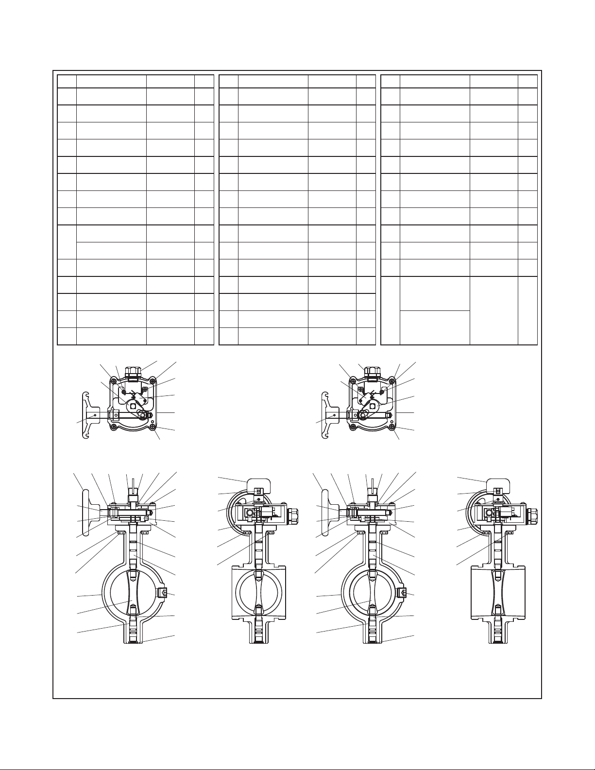
BFV-300 Normally Open Valve
Supervisory Switch Arrangement
BFV-300C Normally Closed Valve
Supervisory Switch Arrangement
No. Part Material Qty.
01 Body
ASTM
A-536
1
02 Upper Stem AI SI 410 1
03 Lower Stem AI SI 410 1
04 Disc EPDM 1
05 O- Rin g (P12) EPDM 4
06
Oiless B/R
(M B1410)
— 4
07
End Cap
2-1/2 – 4 Inch
EPDM 1
08 Gear Box
ASTM
A-536
1
09
Traveling Nut
2 – 6 Inch
Bronze 1
Segment Gear
8 – 12 Inch
C3604BD 1
10 Bushing (2) FD-0205-45 1
11 Cover
ASTM
A- 619
1
12 Bushing Fe 1
13
Headless Wrench
Bolt M5 x 7L
ASTM
A-307
1
14 Stem Housing Fe 1
No. Part Material Qty.
30 Bolt (Round)
ASTM
A-167
3
31 Plate Washer
ASTM
A-167
4
32 Switch Assembly — 1
33 T/R Bolt
ASTM
A-307
2
34
Tapping Screw
ST3.5 x 7.5
S10C 1
35 Tooth Washer 4# S10C 1
36 Lever
ASTM
A- 619
1
37 Connector — 1
38 Sticker — 1
39 Sticker — 1
40
Spring Pin
Ø3 x 0.6T x 25
ASTM
A-228
1
41
Headless Plug
3/8 NPT
2 – 3 Inch
ASTM
A-307
2
Headless Plug
1/2 N PT
4 – 12 Inch
No. Part Material Qty.
15 Spring Pin
ASTM
A-228
1
16 Indicator
ASTM
A- 619
1
17 O-Ring NBR 1
18 Cover Gasket Paper 1
19
Spring Pin
Ø5 x 1T x 25
ASTM
A-228
1
20 O-Ring (P10) EPDM 1
21 Worm Shaf t A ISI 410 1
22 Bushing (1) FD-0205-45 1
23 Collar FD-0205-45 1
24 Spring Washer
ASTM
A-167
4
25
Hex Bolt
M8 x 20L
ASTM
A-167
2
26
Hex Bolt
M8 x 25L
ASTM
A-167
2
27 Gasket Paper 1
28
Spring Pin
Ø4 x 0.8t x 25
ASTM
A-228
1
29 Handwheel
ASTM
A-536
1
26
25
15
27
13
16
30
32
06
23
25
01
04
24
22
21
29 20
28
17 14
40
37
19,
35
36
34
31
38, 39
18
11
10
09
05
03
41
02
08
07
30
33
12
38, 39
28
25
21
22
29
23
24
04
01
06
34
19,
40
17
20
36
35
30
37 33
30
32
31
18
08
05
09
11
10
03
07
41
02
1214
16
13
15
27
26
25
FIGURE 2
MODEL BF V-300/BF V-30 0C GROOVED END BUTTERFLY VALVE
AS S E M B LY
 Loading...