

Tyan THUNDER K8W User Manual

Thunder K8W
S2885
Revision 1.01
Copyright © TYAN Computer Corporation, 2001-2003. All rights reserved. No
part of this manual may be reproduced or translated without prior written
consent from TYAN Computer Corp.
All registered and unregistered trademarks and company names contained in
this manual are property of their respective owners including, but not limited to
the following.
TYAN, Thunder K8W are trademarks of TYAN Computer Corporation.
AMD, Opteron, and combinations thereof are trademarks of AMD Corporation.
AMI, AMIBIOS8 are trademarks of American Megatrends Inc.
Phoenix, PhoenixBIOS are trademarks of Phoenix Technologies Ltd.
Microsoft, Windows are trademarks of Microsoft Corporation.
SuSE,is a trademark of SuSE AG.
Linux is a trademark of Linus Torvalds
IBM, PC, AT, and PS/2 are trademarks of IBM Corporation.Winbond is a
trademark of Winbond Electronics Corporation.
Broadcom
ATI and Rage XL are trademarks of ATI Corporation
Silicon Image, SATALink are trademarks of Silicon Image
Information contained in this document is furnished by TYAN Computer
Corporation and has been reviewed for accuracy and reliability prior to
printing. TYAN assumes no liability whatsoever, and disclaims any express or
implied warranty, relating to sale and/or use of TYAN products including
liability or warranties relating to fitness for a particular purpose or
merchantability. TYAN retains the right to make changes to product
descriptions and/or specifications at any time, without notice. In no event will
TYAN be held liable for any direct or indirect, incidental or consequential
damage, loss of use, loss of data or other malady resulting from errors or
inaccuracies of information contained in this document.
®
is a trademark of Broadcom Corporation and/or its subsidiaries
http://www.TYAN.com
1

BEFORE YOU BEGIN…..................................................................3
CHAPTER 1: INTRODUCTION .......................................................4
H
ARDWARE SPECIFICATIONS
S
OFTWARE SPECIFICATIONS
CHAPTER 2: BOARD INSTALLATION .......................................... 6
2.00 – B
2.01 – B
2.02 – B
2.03 – CPU
2.04 – OEM R
2.05 – I
2.06 – I
2.07 – I
2.08 – A
2.09 – C
2.10 – I
2.11 – C
2.12 – I
2.13 – F
OARD IMAGE
LOCK DIAGRAM
OARD PARTS, JUMPERS AND CONNECTORS
AND CHASSIS FAN CONNECTORS
ESERVED CONNECTORS AND JUMPERS
NSTALLING THE PROCESSOR(S
NSTALLING MOTHERBOARD IN CHASSIS
NSTALLING THE MEMORY
TTACHING DRIVE CABLES
ONNECTING
NSTALLING ADD-IN CARDS
ONNECTING EXTERNAL DEVICES
NSTALLING THE POWER SUPPLY
INISHING UP
......................................................................7
AUX/CD S
.....................................................................27
...........................................................4
............................................................5
..................................................................8
.........................9
.................................14
.....................15
) ..........................................16
...............................19
....................................................20
.................................................22
OUND CABLES & SPEAKERS
.................................................24
........................................25
.........................................26
........... 23
CHAPTER 3: BIOS........................................................................28
3.00 – BIOS S
3.01 – BIOS M
3.02 – BIOS A
3.03 – BIOS PCI/PNP M
3.04 – BIOS B
3.05 – BIOS S
3.06 – BIOS C
3.07 – P
3.08 – BIOS E
CHAPTER 4: DIAGNOSTICS........................................................ 56
APPENDIX I: GLOSSARY.............................................................57
TECHNICAL SUPPORT ................................................................ 62
OWER MENU
ETUP UTILITY
AIN MENU
DVANCED MENU
OOT MENU
ECURITY MENU
HIPSET SETTING MENU
.....................................................................51
XIT MENU
..........................................................28
..............................................................30
......................................................31
ENU
.........................................................40
..............................................................42
.......................................................44
...............................................................55
2
WWW.TYAN.COM
............................................45
Before you begin…
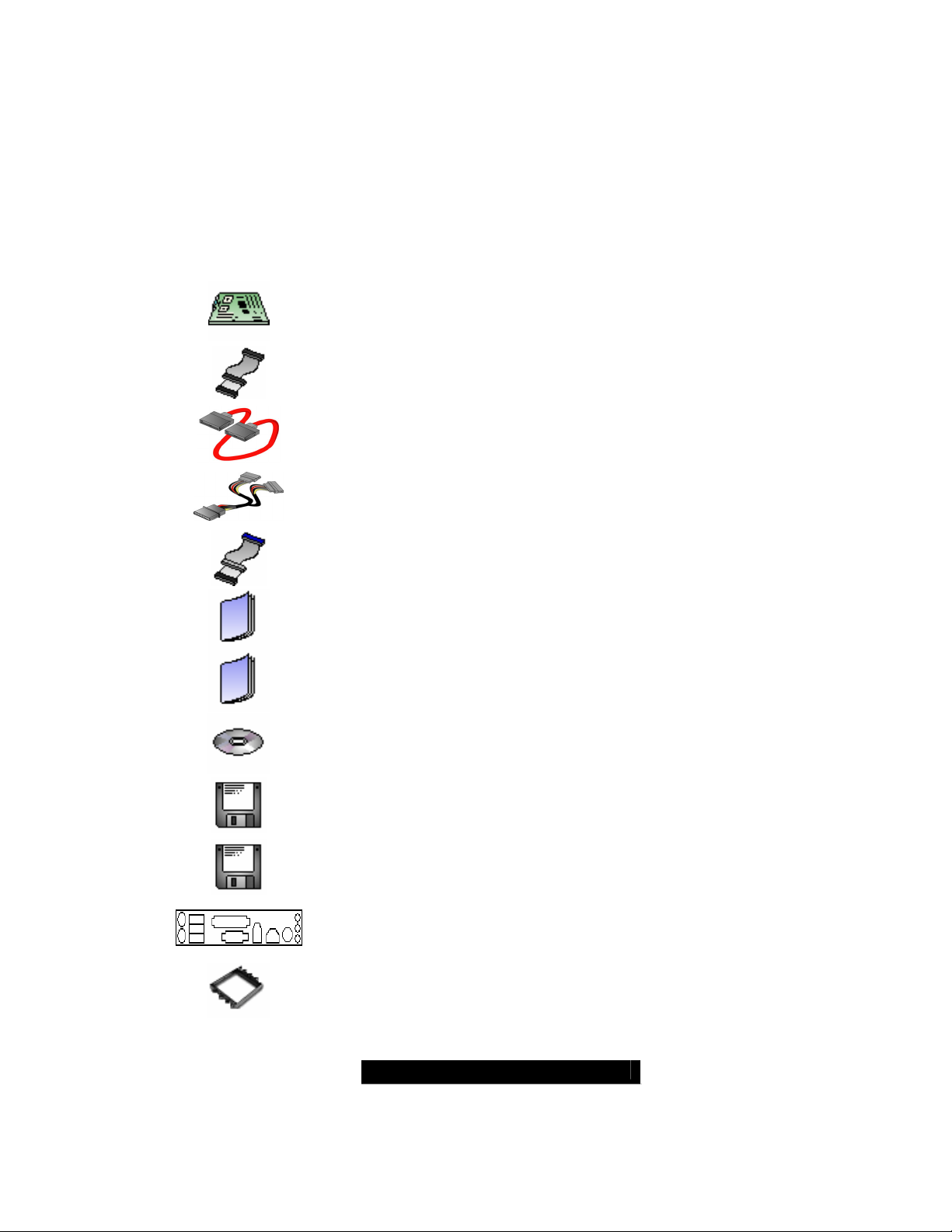
Check the box contents!
The retail motherboard package should contain the following:
1 x Thunder K8W motherboard
1 x 34-Pin floppy drive cable
4 x SATA Data Cable
2 x SATA Drive Power Adapter
1 x Ultra-DMA-100/66 IDE cable
1 x Thunder K8W user’s manual
1 x Thunder K8W Quick Reference guide
1 x TYAN driver CD
1 x Silicon Image SATARAID driver disk
1 x Silicon Image SATALink (IDE) driver disk
2 x CPU Retention Package
If any of these items are missing, please contact your vendor/dealer for
replacement before continuing with the installation process.
3
1 x I/O shield
WWW.TYAN.COM

Chapter 1: Introduction
Congratulations
You are now the owner of the ideal solution for your high-end workstation needs.
This mainboard is the premier choice for CAD/MCAD, DCC, 3D modeling, and
many other multimedia applications. Powered by the AMD Opteron™ Processor
with the scalability of 32-bit and 64-bit support, this platform supports AGP
8X/AGP PRO50 or 110 slot, up to 16GB of DDR memory, Gigabit Ethernet,
SATA, FireWire, and 5.1 surround sound with SPDIF support.
Hardware Specifications
Processor
Dual µPGA 940-pin ZIF sockets
Supports up to two AMD Opteron
™
processors
Two onboard 3-phase VRMs
128-bit DDR dual-channel memory
controller integrated in CPU
Chipset
AMD-8151
AMD-8131
AMD-8111
™
AGP Tunnel
™
PCI-X Tunnel
™
I/O Hub
Winbond W83627HF Super I/O
Memory
128-bit DDR dual-channel memory bus
Eight DIMM sockets (four per CPU)
Supports a total of 16GB of DDR RAM
Requires registered RAM
Supports ECC or non-ECC
Supports DDR400*, 333, or 266
Integrated I/O
One floppy, Two serial (one header
and one connector), and one parallel
port connector
PS/2 KB/mouse connectors
Total five USB 1.1 connections (three
rear connectors and two USB headers)
Expansion Slots
One 8x AGP/AGP-PRO 110W slot
Four PCI-X slots
- Two 64-bit (3.3v) PCI-X slots support
up to 133 MHz on Bus B
- Two 64-bit (3.3v) PCI-X slots support
up to 100 MHz on Bus A
One legacy 32-bit 33MHz PCI slot (5v)
Total of six usable slots
System Management
Analog Devices ADT7463 monitor IC
connected to SMBus 1.0
Total six 3-pin fan headers with
tachometer monitoring and PWM
3-pin Chassis Intrusion header
Integrated Enhanced IDE Controller
Two ports for up to four EIDE devices
Supports up to ATA-133 IDE devices
Integrated Audio
AMD-8111 AC97 Audio Controller
Analog Devices AD1981b Audio Codec
One RCA SPDIF digital connector
Line-in, line-out, mic-in, rear connectors
Headphone & MIC front panel headers
Two 4-pin ATAPI Audio headers
4
WWW.TYAN.COM

Integrated SATA Controller
Silicon Image SIL3114 SATA
Four SATA 1.0 channels
IDE RAID 0, 1, 0+1 (option)
48-bit LBA support
Integrated PCI Firewire
TI TSB43AB22 IEEE1394A controller
One external connector and one pin
header for front panel connectors
Integrated Gigabit Ethernet
Broadcom
®
BCM5703C Gigabit
Ethernet
RJ-45 LAN connectors with LEDs
Connected to PCI-X Bridge A
(64-bit 100MHz max)
Regulatory
FCC Class B (Declaration of
Conformity)
European Community CE (Declaration
of Conformity)
*DDR 400 supported by AMD Opteron™
246 or higher
BIOS
®
AMIBIOS8
on 4Mbit LPC Flash ROM
ACPI 1.0b & 2.0
Serial Console Redirect
PXE via Ethernet
USB device boot
48-bit LBA Support
Form Factor
SSI EEB v3.0 footprint (13 x12”
330.2x304.8 mm) Fits many EATX &
SSI-compliant tower chassis
EPS12V or SSI Workstation Spec 2.0
24pin + 8pin + 6pin (optional) power
connector
Serial (one) and VGA (one) connector
Stacked USB 1.1 (three) connectors
Stacked PS/2 KB/Mouse connectors
One RJ-45 LAN connectors with LED
Line-in/Out, Mic, & SPDIF Audio
Connectors
Software Specifications
OS (Operating System) Support
Microsoft Windows 2000, XP, Server 2003
SuSE Server 8.2/ Workstation 9.0 for AMD-64
Turbo Linux for AMD64
Other distributions of Linux pending validation
TYAN Computer Corp. reserves the right to add, discontinue, or modify support for any
OS with or without notice.
Please visit TYAN’s Website at http://www.TYAN.com
. There you can find
information on all of TYAN’s products with FAQs, manuals, drivers, and BIOS
upgrades.
5
WWW.TYAN.COM

Chapter 2: Board Installation
Precaution: The Thunder K8W supports EPS12V/SSI type power supplies
(24pin + 8pin + 6pin) and will not operate with any other types. For proper power
supply installation procedures see page 26.
DO NOT USE ATX 2.x, ATX12V or ATXGES power supplies as they will damage
the board and void your warranty.
How to install our products right… the first time
The first thing you should do is read this user’s manual. It contains important
information that will make configuration and setup much easier. Here are some
precautions you should take when installing your motherboard:
(1) Ground yourself properly before removing your motherboard from the
antistatic bag. Unplug the power from your computer power supply and
then touch a safely grounded object to release static charge (i.e. power
supply case). For the safest conditions, TYAN recommends wearing a
static safety wrist strap.
(2) Hold the motherboard by its edges and do not touch the bottom of the
board, or flex the board in any way.
(3) Avoid touching the motherboard components, IC chips, connectors,
memory modules, and leads.
(4) Place the motherboard on a grounded antistatic surface or on the
antistatic bag that the board was shipped in.
(5) Inspect the board for damage.
The following pages include details on how to install your motherboard into your
chassis, as well as installing the processor, memory, disk drives and cables.
NOTE
DO NOT APPLY POWER TO THE BOARD IF IT HAS BEEN
DAMAGED
6
WWW.TYAN.COM
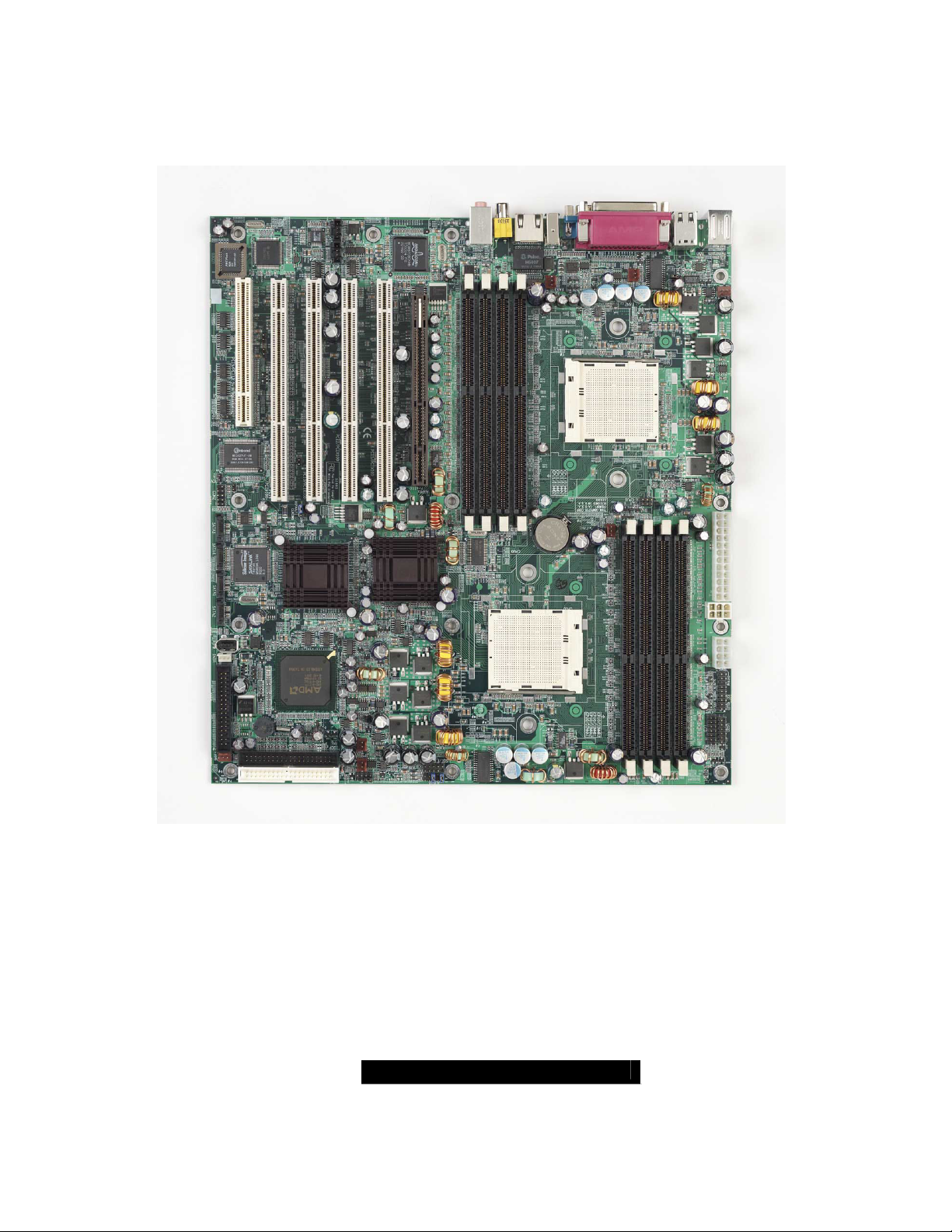
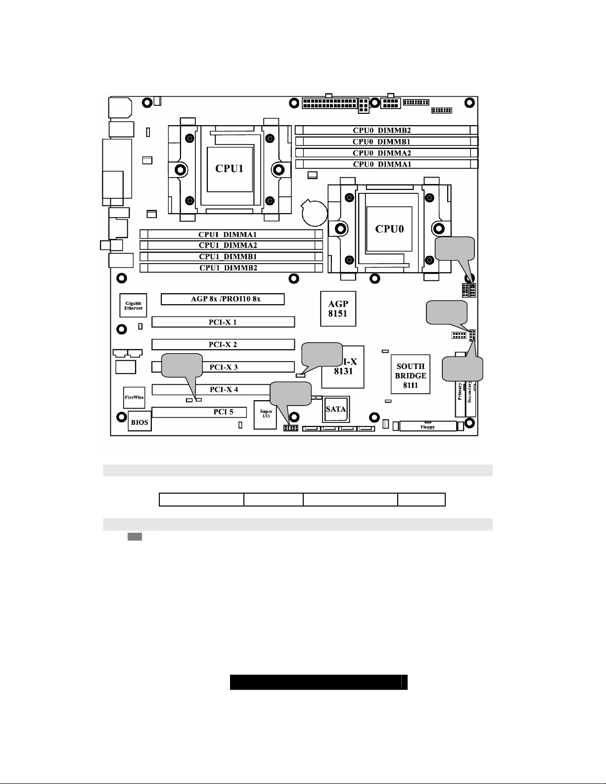
2.00 – Board Image
This picture is representative of the latest board revision available at the
time of publishing. The board you receive may or may not look exactly like
the above picture.
The following page includes details on the vital components of this motherboard.
7
WWW.TYAN.COM
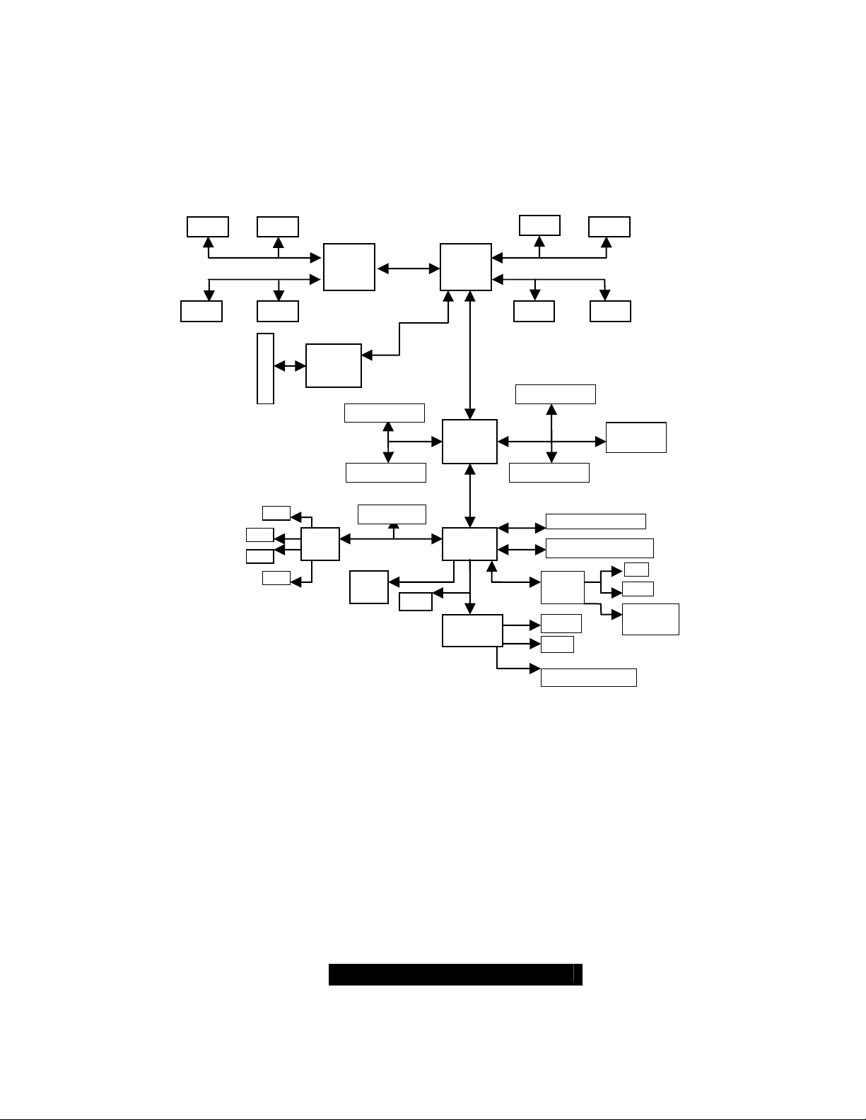
2.01 – Block Diagram
A
A
S2885 Thunder K8W Block Diagram
DIMM4 DIMM2
Upper 64-bit Upper 64-bit
CPU 1
Lower 64-bit
AGP 8X Pro
AGP
8151
PCI-X Slot 1
PCI-X BUS B
PCI-X Slot 2
1
2
3
SATA
3114
4
PCI Slot 5
PCI 32bit/33MHz
SMBUS
DT
7463
BIOS
CPU 0
PCI-X
8131
I/O Hub
8111
LPC
Super
I/O
DIMM2
128-Bit Dual Channel 128-Bit Dual Channel
DIMM1 DIMM3 DIMM1 DIMM3
PCI-X Slot 3
PCI-X BUS A
PCI-X Slot 4
ATA-133 EIDE x2
USB 1.1 front & rear
Codec
Floppy
PS/2
D1981
DIMM4
Lower 64-bit
Broadcom
5703C
CD
AUX
SPDIF &
Audio-out
Serial & Parallel
8
WWW.TYAN.COM
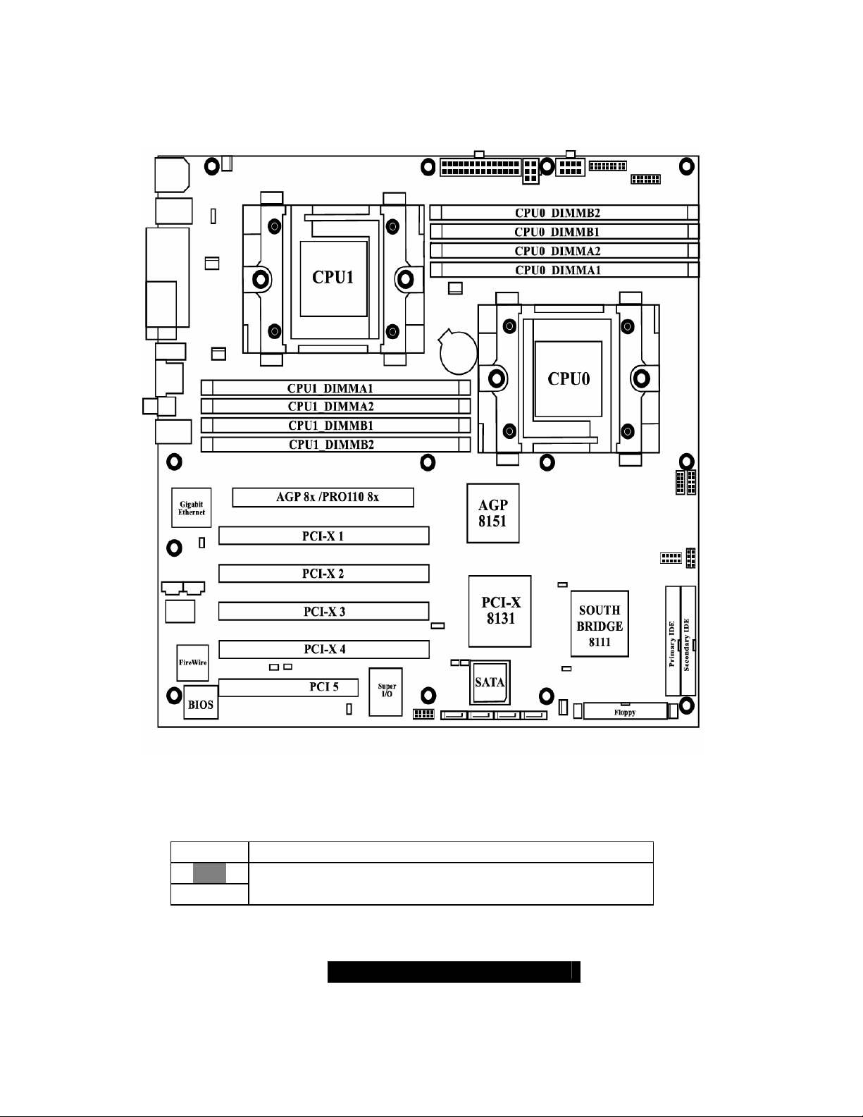
2.02 – Board Parts, Jumpers and Connectors
This diagram is representative of the latest board revision available at the time of
publishing. The board you receive may not look exactly like the above diagram.
Jumper Legend
OPEN - Jumper OFF without jumper cover
CLOSED - Jumper ON with jumper cover
Key Pin Missing pin to indicate proper orientation
9
WWW.TYAN.COM
J39
J43
J4
J34
J14
J42
J4 SMBus 1.1 Connector
Use this connector to connect external SMBUS devices
Pin1: SMB_DATA Pin2: GND Pin3: SMBUS_CLK Pin4: NC
J14 Onboard Buzzer/Speaker header
Close Pin-3 and 4 (Default) - Onboard Buzzer Enabled
Open Pin- 3 and 4 - Disable onboard buzzer or connect to chassis
speaker
10
WWW.TYAN.COM
 Loading...