

Page 1

S2727
Tiger GC-SL
///
Revision 1.01
Copyright © TYAN Computer Corporation, 2002- 2003. All rights reserved. No part of this manual
may be reproduced or translated without prior written consent from TYAN Computer Corp.
All registered and unregistered trademarks and company names contained in this manual are
property of their respective owners including, but not limited to the following.
TYAN, Tiger GC-SL S2727 are trademarks of TYAN Computer Corporation.
Intel, Pentium, and combinations thereof are trademarks of Intel Corporation.
Adaptec is a trademark of Adaptec, Incorporated.
AMI, AMIBIOS are trademarks of American Megatrends, Incorporated.
Microsoft, Windows are trademarks of Microsoft Corporation.
National is a trademark of National Semiconductor.
Promise is a trademark of Promise Technology.
IBM, PC, AT, and PS/2 are trademarks of IBM Corporation.
Winbond is a trademark of Winbond Electronics Corporation.
Portable Document Format (PDF) is a trademark of Adobe Corporation.
Information contained in this document is furnished by TYAN Computer Corporation and has been
reviewed for accuracy and reliability prior to printing. TYAN assumes no liability whatsoever, and
disclaims any express or implied warranty, relating to sale and/or use of TYAN products including
liability or warranties relating to fitness for a particular purpose or merchantability. TYAN retains the
right to make changes to product descriptions and/or specifications at any time, without notice. In
no event will TYAN be held liable for any direct or indirect, incidental or consequential damage,
loss of use, loss of data or other malady resulting from errors or inaccuracies of information
contained in this document.
1
http://www.TYAN.com
Page 2

Before you begin…
Chapter 1: Introduction
1.1 Congratulations!
1.2 Specifications
Chapter 2: Board Installation
2.0 Board Image
2.1 Board Parts
2.2 Jumper Setting List
2.3 Connector List
2.4 Front Panel Connector
2.5 Clear CMOS
2.6 Onboard ATI RAGE XL Graphics
2.7 Onboard Intel 82551QM LAN
2.8 Ext. Intel 82551 LAN LED Header
2.9 Onboard Intel 82540EM LAN
2.10 Ext. Intel 82540 LAN LED Header
2.11 CPU Thermal-Trip
2.12 CPU-Hot Warning LED For CPU1
2.13 CPU-Hot Warning LED For CPU2
2.14 Watchdog Timer Control
2.15 Fan Connectors
2.16 Serial Header (COM2)
2.17 USB Header
2.18 Mounting the Motherboard
2.19 Xeon Reinforcement Kit Installation
2.20 Installing the Processors & Heatsinks
2.21 Installing the Memory
2.22 Attaching Drive Cables
2.23 Installing Add- In Cards
2.24 Connecting External Devices
2.25 Installing the Power Supply
2.26 Finishing UP
Chapter 3: BIOS
3.1 BIOS Menu Bar
3.2 BIOS Legend Bar
3.3 BIOS Main Menu
3.4 BIOS Advanced Menu
3.5 BIOS PCI/PnP Menu
3.6 BIOS Boot Menu
3.7 BIOS Chipset Menu
3.8 BIOS ACPI Menu
3.9 BIOS Security Menu
3.10 B IOS Exit Menu
Chapter 4: Diagnostics
4.1 Beep Codes
4.2 Flash Utility
Appendix I: Glossary
Appendix II: SMDC Information
Appendix III: S2727 With Tyan Riser Cards
Technical Support
……………………………………………..Page 3
..……………………………………………Page 4
……………………………………………..Page 4
……………………………………………..Page 4
….….………………………………………Page 6
……………………………………………..Page 7
……………………………………………..Page 8
……………………………………………..Page 9
……………………………………………..Page 9
………………….………………………..Page 10
……………………………………………Page 11
……………………………………………Page 11
……………………………………………Page 12
……………………………………………Page 12
……………………………………………Page 13
……………………………………………Page 13
……………………………………………Page 14
……………………………………………Page 14
……………………………………………Page 15
……………………………………………Page 15
……………………………………………Page 16
……………………………………………Page 16
……………………………………………Page 17
……………………………………………Page 18
……………………………………………Page 19
……………………………………………Page 21
……………………………………………Page 22
……………………………………………Page 24
……………………………………………Page 26
……………………………………………Page 27
……………………………………………Page 28
……………………………………………Page 29
……………………………………………Page 30
……………………………………………Page 31
……………………………………………Page 31
……………………………………………Page 32
……………………………………………Page 33
……………………………………………Page 36
……………………………………………Page 38
……………………………………………Page 39
……………………………………………Page 40
……………………………………………Page 41
……………………………………………Page 42
……………………………………………Page 43
……………………………………………Page 43
……………………………………………Page 44
……………………………………………Page 45
……………………………………………Page 50
……………………………………………Page 51
……………………………………………Page 52
2
http://www.TYAN.com
Page 3
Before you begin…
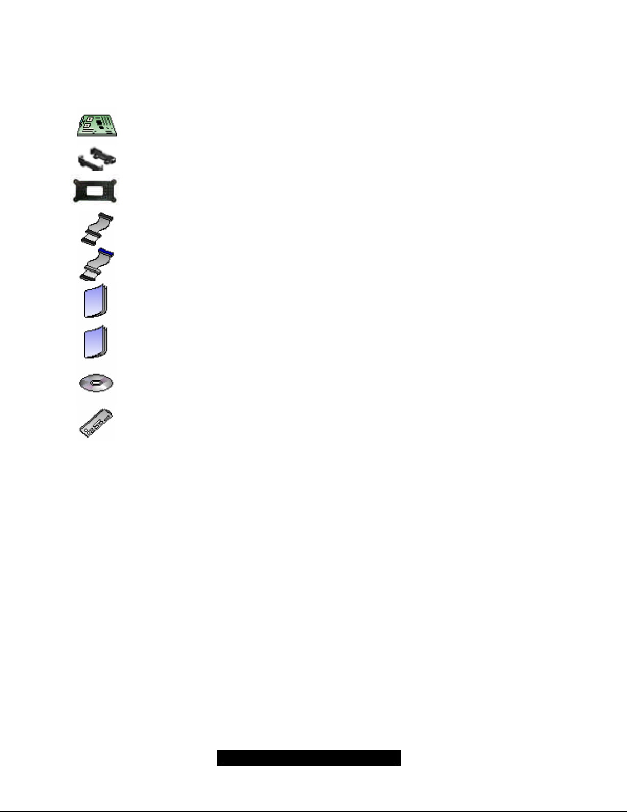
Check the box contents!
The retail motherboard package should contain the following:
1x Tiger GC-SL motherboard
2x CPU Retention Reinforcement back -plates with screws
1 x Ultra-DMA-133/100/66/33 IDE cable
2x CPU retentions
1x 34-Pin floppy drive cable
1x Tiger GC-SL User’s Manual
1x Tiger GC-SL Quick Reference (sticker)
1x TYAN driver CD
1x I/O shield
If any of these items are missing, please contact your vendor/dealer for replacement before
continuing with the installation process.
3
http://www.TYAN.com
Page 4

Chapter 1: Introduction
1.1 – Congratulations!
You have purchased one of the most powerful dual Intel processor solutions, the Tiger GC-SL
S2727. Based on Serverworks Grand Champion SL chipset, the Tiger GC-SL S2727 is HyperThreading ready - utilizing onboard resources so that a second thread of data can be processed in
a single processor. Compatible with both ATX12V and EPS12V power supplies, this platform
offers convenient remote Intelligent Platform Management Interface (IPMI) monitoring through a
Server Management Daughter Card. The Tiger GC-S L S2727 also features an ATX form factor,
64-bit PCI, Gigabit Ethernet port, Fast Ethernet port, and an onboard ATI 8MB PCI RAGE XL
VGA, which provides an advanced and versatile solution for your server needs.
Remember to visit Tyan’s web site at http://www.tyan.com. There you can find information on all of
Tyan’s products with FAQs, a complete distributors list, and BIOS setting explanations.
1.2 – Specifications
Processor
• Dual mPGA604 ZIF Sockets
• Supports one or two Intel Xeon processors
with 512KB of integrated L2 cache
• Onboard 4- phase VRM (VRM 9.1 spec)
• Front-Side Bus support for 533 & 400 MHz
Chipset
• ServerWorks GC-SL chipset
• CMIC-SL, CSB6
• National PC87417 Super I/O
• Winbond W83782D Hardware Monitor ASIC
Memory
• Four DDR DIMM sockets (minimum one single
DIMM)
• Supports up to 4GB maximum memory
• Supports Registered ECC DDR (72 -bit)
memory modules
Expansion Slots
• Three 64/32-bit/33MHz PCI 2.2 slots
• Two 32-bit/33MHz PCI 2.2 slots
• Total five usable slots
Integrated PCI IDE
• Triple-channel PCI bus-master mode
• The primary and secondary channels support
ATA -100/66/33 IDE and ATAPI compliant
devices.
• The tertiary channel supports ATA - 66/33 IDE
and ATAPI compliant devices.
• Supports up to six Enhanced IDE devices
Integrated LAN Controller(s)
Two or one onboard Ethernet NICs
• Intel 82540EM Gigabit Ethernet controller
(not included with S2727GN version)
• One RJ-45 LAN connector with LEDs
• Operating at a 32-bit 33 MHz PCI bus
• Intel 82551QM Fast Ethernet controller
• One RJ-45 LAN connector with LE Ds
• Operating at a 32-bit 33 MHz PCI bus
Intelligent Platform Management Interface
(with optional Tyan’s M3289 SMDC)
• QLogic Zircon Baseboard Management
Controller (BMC) based on powerful ARM7
technology
• Tailored for IPMI highest 1.5 specifications
• Supports KCS and BT styles
• Supports flexible Windows and Linux based
Management Solution
• Supports RMCP and SNMP protocols
• Supports ASF standard and EMP
• I2C serial multi -master controllers and
UARTs
• Built-in IPMB connector
• Supports remote Power on/off and reset
support (IPMI- over-LAN)
• Server Management Daughter card
connection via a built- in 2x25 header
Integrated 2D/3D Graphics
• ATI RAGE XL graphics controller
• 8MB frame buffer (SDRAM)
• Standard 15-pin analog VGA port
4
http://www.TYAN.com
Page 5

Integrated I/O
• One floppy connector supports up to two drives
• Two 9-pin 16550-based serial ports
(COM2 via an optional cable)
• One 25-pin SPP/ECP/EPP parallel port header
• Four USB ports (2 rear connectors and 2 front
side USB headers for an optional cable)
• PS/2 keyboard and mouse connetor s
System Management
• Winbond W83782D or optional ADI ADM1027
• Total six 3-pin fan headers with tachometer
monitoring
• Three 3-pin fan headers and PWM control
• 2- pin chassis intrusion header
• Temperature and voltage monitoring
• Watchdog timer
BIOS
• AMI BIOS on 4Mbit Flash ROM
• Supports ACPI
• Auto detection of memory size
• Auto configuration of IDE hard drive types
• Multiple boot options
• User settings of hardware monitoring
• Power Management: ACPI S1, S4, and S5
Form Factor
• Standard ATX 2.03 (12” x 9.6”), 6-layer PCB
• ATX12V/EPS12V power connector
• Stacked Mouse/Keyboard Ports
• Stacked USB (two) connectors
• One serial connector and one VGA connector
• Two RJ- 45 side-by-side connectors with
LEDs (S2727GN version has only one RJ-45.)
Regulatory
• FCC DoC (Declaration of Conformity)
• European CE (Declaration of Conformity)
Hyper-Threading Support In:
Windows 2000 Server
Windows 2000 Advanced Server
Windows XP Pro
Windows NT 4.0 Server
Linux (Kernel 2.4.18)
Novell Netware 6 with Support Pack 1
TYAN reserves the right to add support or
discontinue support for any OS with or
without notice.
5
http://www.TYAN.com
Page 6
Chapter 2: Board Installation
Installation
You are now ready to install your motherboard. The mounting hole pattern of the Tiger GC -SL
matches the ATX specifications. Before continuing with installation, confirm that your chass is
supports a standard ATX motherboard. Two CPU retention reinforcement back-plates are
included for securing the CPU heatsinks.
How to install our products right…. the first time!
The first thing you should do is read this user’s manual. It contains im portant information that will
make configuration and setup much easier. Here are some precautions you should take when
installing your motherboard:
(1) Ground yourself properly before removing your motherboard from the antistatic bag.
Unplug the power from your computer power supply and then touch a safely grounded
object to release static charge (i.e. power supply case). For the safest conditions, Tyan
recommends wearing a static safety wrist strap.
(2) Hold the motherboard by its edges and do not touch the bottom of the board, or flex the
board in any way.
(3) Avoid touching the motherboard components, IC chips, connectors, memory modules,
and leads.
(4) Place the motherboard on a grounded antistatic surface or on the antistatic bag that the
board was shipped in.
(5) Inspect the board for damage.
The following pages include details on how to install your motherboard into your chassis, as well
as installing the processor, memory, disk drives and cables.
NOTE DO NOT APPLY POWER TO THE BOARD IF IT HAS BEEN DAMAGED
6
http://www.TYAN.com
Page 7

2.0 – Board Image
The following is an image of the S2727 Tiger GC-SL.
The above photograph is purely representative. Due to engineering updates and new board
revisions, certain components may change and or be repositioned. The picture above may
or may not look exactly like the board you received.
The following page includes details on the vital components of this motherboard.
7
http://www.tyan.com
Page 8
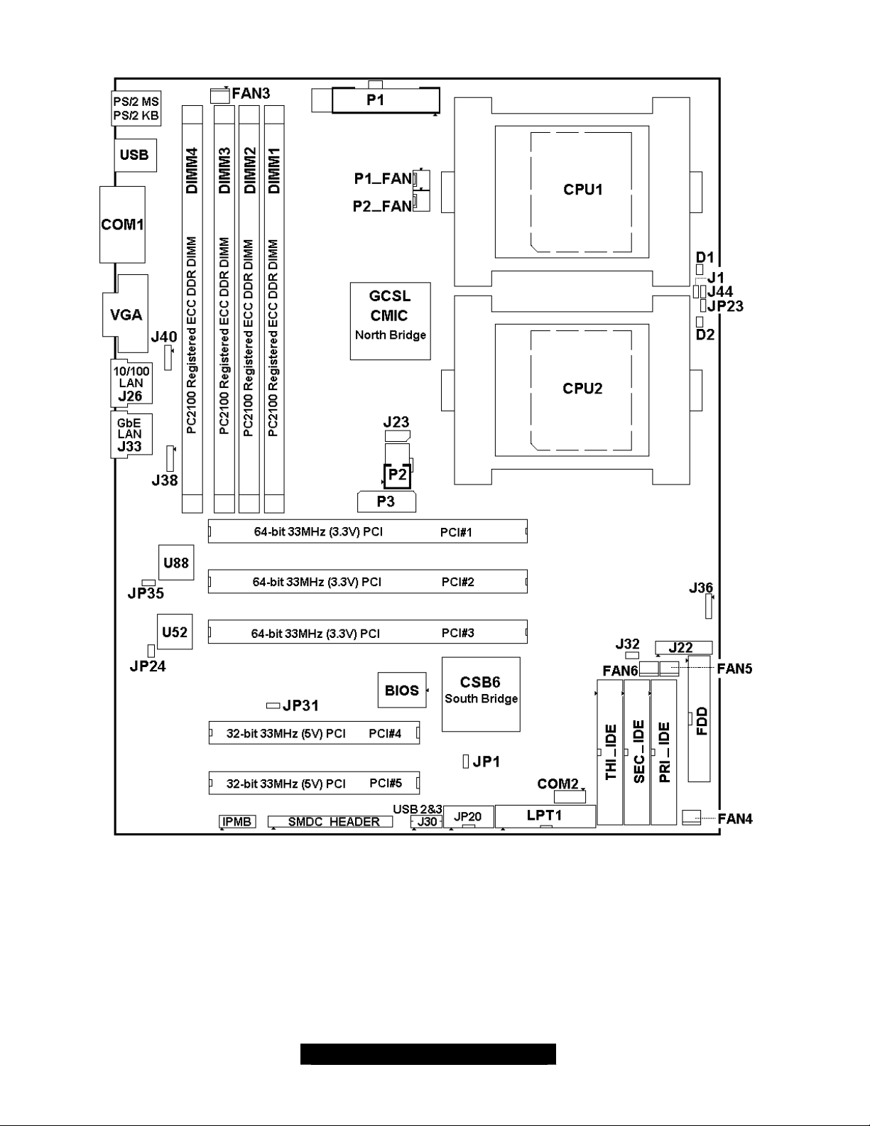
2.1 – Board Parts
This jumper diagram is representative of the latest board revision available at the time of
publishing. The board you receive may or may not look exactly like the above diagram.
The board parts are not to scale.
8
http://www.tyan.com
Page 9

2.2 – Jumper Settings
Jumper Function Settings Ref. Page
JP1
JP20
JP23
JP24
JP31
JP35
2.3 – Connectors
CMOS Clear
Reserved
Enable/Disable CPU Thermaltrip power down feature
Enable/Disable onboard Intel
82551QM Fast Ethernet NIC
Enable/Disable onboard ATI
Rage XL PCI VGA controller
Enable/Disable onboard Intel
82540EM Gigabit Ethernet NIC
Open: Normal (Default)
Close: CMOS Clear Mode
Open: Enable (Default)
Close: Disable
Open: Enable (Default)
Close: Disable
Open: Enable (Default)
Close: Disable
Open: Enable (Default)
Close: Disable
Page 11
Page 11
Page 11
Page 12
Page 14
Page 13
Connector Function
J1
J21
J22
J26
J27
J30
J32
J33
J36
J38
J40
COM2
CPUFAN1
CPUFAN2
FAN3
FAN4
FAN5
FAN6
External LED header for Processor-hot warning; same as onboard LED D1
PS/2 keyboard (lower) and PS/2 mouse (upper) connectors
Front panel header
RJ45 LAN connector for onboard Intel 82551QM NIC
VGA connector for onboard ATI Rage XL PCI VGA
Front USB headers
Hardware monitor warning buzzer header (optional)
RJ45 LAN connector for onboard Intel 82540EM NIC
External speaker header
Auxiliary LAN LED header for onboard Intel 82540EM NIC
Auxiliary LAN LED headers for onboard Intel 82551QM NIC
COM2 2x5 pin header
3- pin CPU1 fan connector with PWM fan control and fan speed reading
3- pin CPU2 fan connector with PWM fan control and fan speed reading
3- pin fan connector with PWM fan control and fan speed reading
3- pin fan connector with PWM fan control and fan speed reading
3- pin CPU fan connector with fan speed reading
3- pin fan connector with PWM fan control and fan speed reading
9
http://www.tyan.com
Page 10

Jumper Legend
Jumper OFF (without jumper cap)
Jumper ON (with a jumper shunt to cover the jumper pins)
2.4 – Front Panel Connector (J22)
Your chassis will usually come with connectors to install onto the motherboard, such as HDD and
Power LEDs. The Front Panel Connector (J22) has been implemented for such purposes.
J22
Front Panel Connector
Pin 1: Hard disk drive LED +
Pin 2: Power LED +
Pin 3: Hard disk drive LED -
Pin 4: Power LED -
Pin 5: GND
Pin 6: Power button (LOW asserted)
Pin 7: Reset button (LOW asserted)
Pin 8: GND
Pin 9: +5V
Pin10: Sleep button (LOW asserted)
Pin11: NC (Not Connected)
Pin12: GND
Pin13: GND
Pin14: Key
Pin15: NC (Not Connected)
Pin16: NC (Not Connected)
Pin17: Chassis intrusion (LOW asserted)
Pin18: GND
10
http://www.tyan.com
Page 11

2.5 – Clear CMOS (JP1)
JP1
2.6 – Onboard ATI RAGE XL Graphics (JP31)
CMOS Reset
You can reset the CMOS settings in case an
incorrect setting causes system instability or
you have forgotten your system/setup
password or have just flashed your BIOS by
using these jumpers.
• Power off system and disconnect the AC
• Set jumper JP1 to Clear CMOS.
• Power system on and wait for the screen
• Power off system and disconnect the AC
• Power system on and g o to BIOS Setup.
(OPEN)
Normal (default) Clear CMOS
power from the power supply.
to show this message: “CMOS Settings
Wrong, CMOS Checksum Bad”. Now the
CMOS is cleared.
power from the power supply and set
jumper JP1 to Normal (OPEN) for normal
operations.
Load and save setup defaults.
(CLOSE)
JP31
Onboard ATI RAGE XL Graphics
(OPEN)
Enabled (Default) Disabled
OPEN: The jumper enables the onboard ATI
RAGE XL graphics co ntroller. You can also use
the onboard video in conjunction with another
PCI graphics card for multiple monitor support.
CLOSE: The jumper disables the onboard ATI
RAGE XL graphics controller.
(CLOSE)
11
http://www.tyan.com
Page 12

2.7 – Onboard Intel® 82551QM Fast Ethernet Controller (JP24)
JP24
2.8 – External LAN LED Header for o nboard Intel 82551QM LAN (J40)
Onboard Intel® 82551QM (LAN1)
(OPEN)
Enabled (Default) Disabled
The onboard LAN1, Intel 82551QM Fast
Ethernet controller, with its RJ-45 (J26, next to
VGA connector in the rear I/O.) can be enabled
or disabled by JP24.
OPEN: The jumper enables the onboard Intel
82551QM 10/100 Mbps Fast Ethernet controller.
CLOSE: The onboard Intel 82551QM 10/100
Mbps Fast Ethernet controller can be disabled
by placing a jumper shunt on jumper JP24.
(CLOSE)
J40
Onboard Intel® 82551QM (LAN1)
J40 is a 4- pin external LAN LED header for
onboard LAN1 / Intel 82551QM controller.
The LED indication is similar to the LEDs on J26.
J40
LED indications:
Pin 1: Yellow LED +
Pin 2: Yellow LED -
Link not established:
Yellow LED: Off Green LED: Off
Link at 10Mbps without activity
Yellow LED: Off Green LED: On
Link at 10Mbps with activity
Yellow LED: Off Green LED: Blink
Link at 100Mbps without activity
Yellow LED: On Green LED: Off
Link at 100Mbps with activity
Yellow LED: Blink Green LED: Off
Pin 3: Green LED +
Pin 4: Green LED -
12
http://www.tyan.com
Page 13
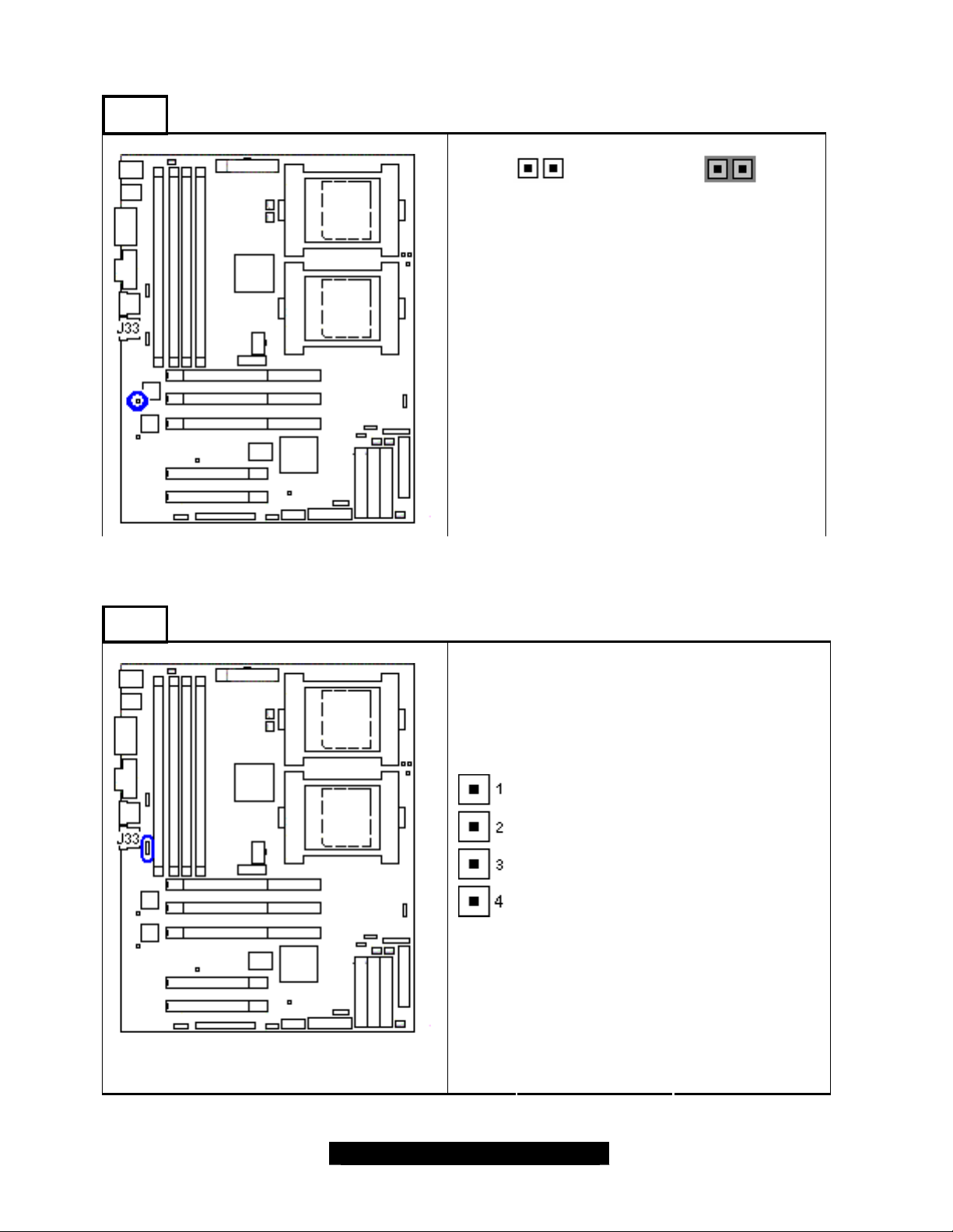
2.9 – Onboard Intel® 82540EM Gigabit Ethernet Controller (JP35)
JP35
Onboard Intel® 82540EM LAN2 (for S2727GNN only)
(OPEN)
Enabled (Default) Disabled
The onboard LAN2, Intel 82540EM Gigabit
Ethernet controller, with its RJ-45 (J33) can be
enabled or disabled by JP35.
OPEN: The jumper enables the onboard Intel
82540EM 10/100/1000 Mbps Ethernet controller.
CLOSE: The onboard Intel 82540EM
10/100/1000 Mbps Ethernet controller can be
disabled by placing a jumper shunt on jumper
JP35.
2.10 – External LAN LED Header for o nboard Intel 82540EM LAN (J38)
J38
Onboard Intel® 82540EM LAN2
J38 is a 4- pin external LAN LED header for
onboard LAN2/Intel 82540EM Gigabit controller.
The LED indication is similar to the LEDs on J33.
(CLOSE)
J38
LED indications:
Pin 1: Yellow LED +
Pin 2: Yellow LED -
Pin 3: Green LED +
Pin 4: Green LED -
Link not established:
Yellow LED: Off Green LED: Off
Link at 10Mbps without activity
Yellow LED: Off Green LED: On
Link at 10Mbps with activity
Yellow LED: Off Green LED: Blink
Link at 100Mbps without activity
Yellow LED: On Green LED: Off
Link at 100Mbps with activity
Yellow LED: Blink Green LED: Off
Link at 1000Mbps without activity
Yellow LED: On Green LED: On
Link at 1000Mbps with activity
Yellow LED: Blink Green LED: Blink
13
http://www.tyan.com
Page 14
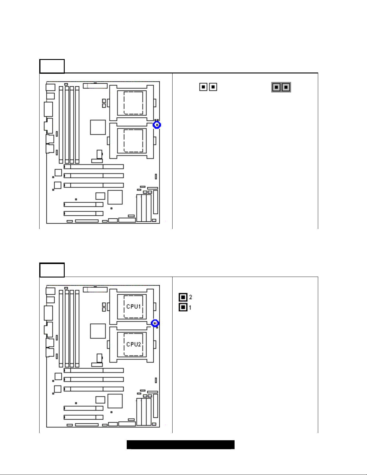
2.11 – CPU Thermal-Trip (JP23)
The processor protects itself from overheating by the use of an internal integrated thermal sensor.
When the Thermal -Trip is enabled, the system will shut off if temperature reaches about 135º
Celsius at CPU junction temperature. The processor then stops all its executions.
JP23
2.12 – CPU-Hot Warning LED Header For CPU1 (J1)
CPU Thermal-Trip Protection
(OPEN)
Enabled (Default) Disabled
OPEN: CPU Thermal-Trip Protection is enabled.
CLOSE: CPU Thermal -Trip Protection is
disabled. System will not be forced to shut off,
when CPU Thermal-Trip occurs. In this case,
overheating could damage the processor.
(CLOSE)
J1
CPU- Hot Warning LED Header For CPU1
J1 is an external LED header to indicate CPU1
signal PROCHOT# status. When CPU1 gets
too hot, the CPU1 signal PROCHOT# will be
asserted before CPU1 reaches cataclysmal
fai lure or damage.
The onboard LED (D1) acts as same as J1 to
indicate CPU1 processor overheating.
J1
Pin 1: LED +
Pin 2: LED -
14
http://www.tyan.com
Page 15
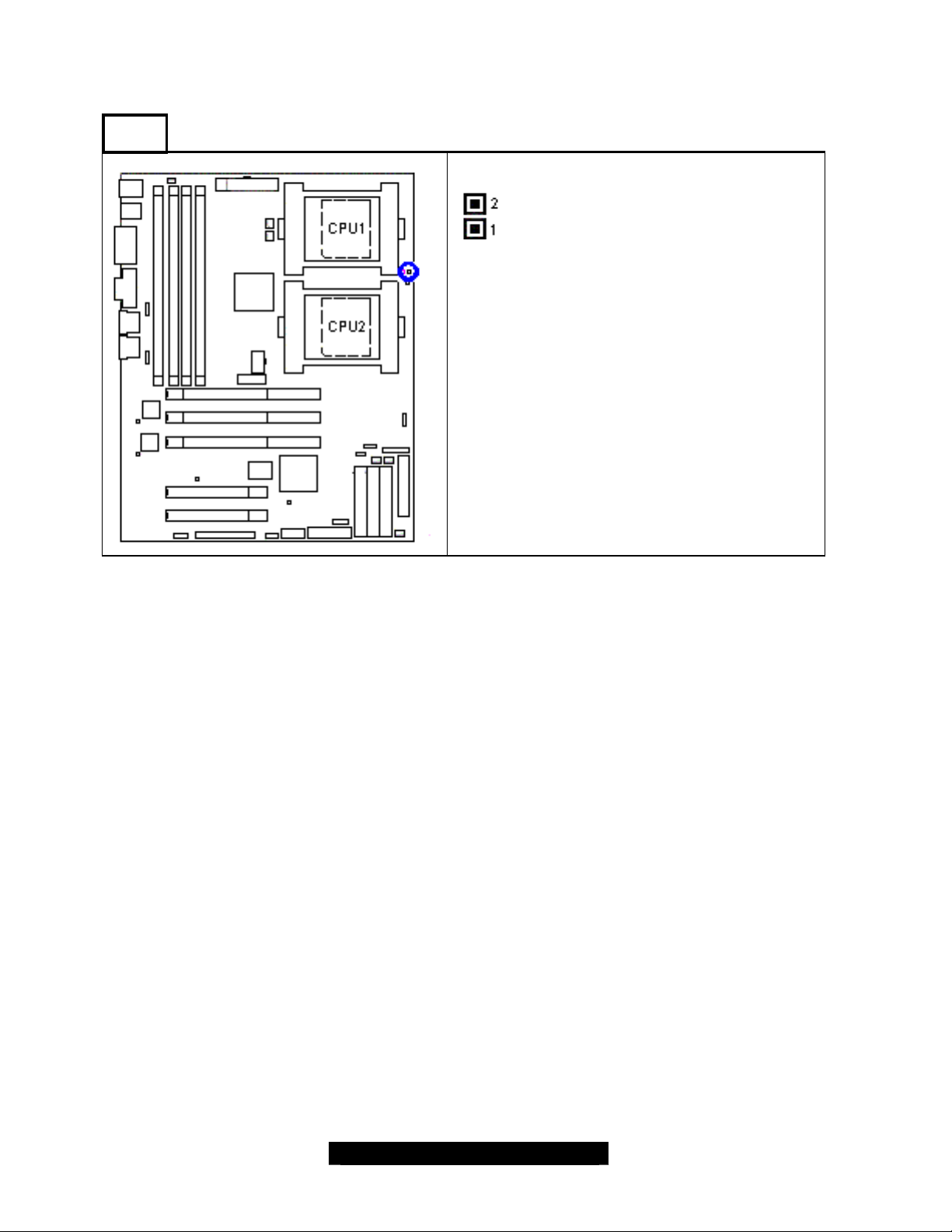
2.13 – CPU-Hot Warning LED Header For CPU2 ( J44)
J44
CPU- Hot Warning LED Header For CPU2
J44
J44 is an external LED header to indicate CPU2
signal PROCHOT# status. When CPU2 gets
too hot, the CPU2 signal PROCHOT# will be
asserted before CPU2 reaches cataclysmal
failure or damage.
The onboard LED (D2) acts as same as J44 to
indicate CPU2 processor overheating.
Pin 1: LED +
Pin 2: LED -
15
http://www.tyan.com
Page 16
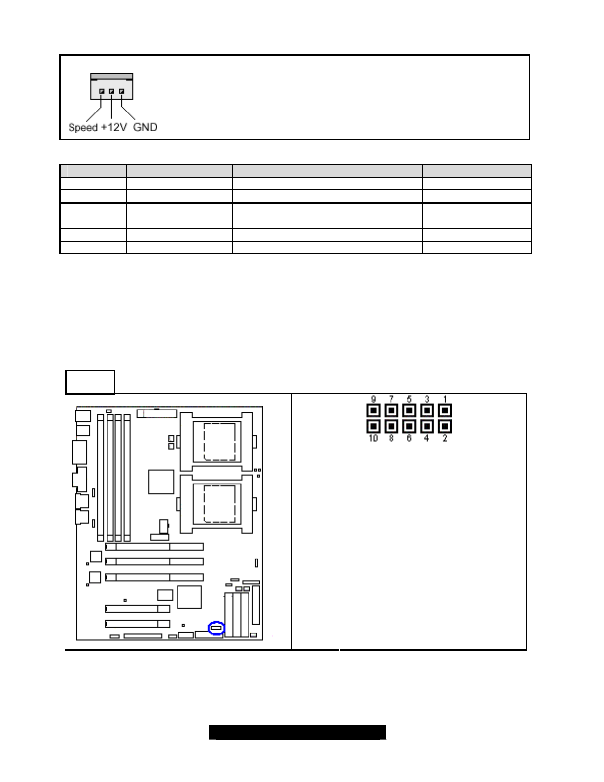
2.15 – Fan Connectors
COM2
FAN PWM Fan Control Fan Tachometer/Speed Reading Max. Current
CPUFAN1
CPUFAN2
FAN3
FAN4
FAN5
FAN6
2.16 – Serial Port Header (COM 2)
Use these headers to connect cooling fans, both chassis and processor
fans, to your motherboard. Cooling fans help keep the system more
stable and operating reliably for its product life.
+12Volts fans supported
No Yes 1.5 Amp
No Yes 1.5 Amp
Yes Yes 1.2 Amp
Yes Yes 1.2 Amp
Yes Yes 1.2 Amp
No Yes 1.5 Amp
The Second Serial Port Header
Pin 1: DCD
Pin 2: RXD
Pin 3: TXD
Pin 4: DTR-
Pin 5: GND
Pin 6: DSR
Pin 7: RTS
Pin 8: CTS
Pin 9: RI
Pin10: NC
16
http://www.tyan.com
Page 17
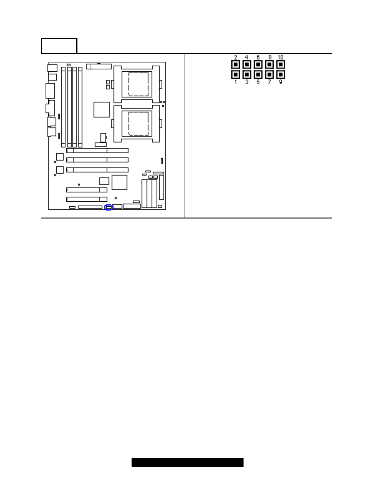
2.17 – USB Header (J30)
J30
USB #2 & #3 Header
Note:
The external USB cable is optional and not
included in the standard shipping box.
Pin 1: USB POWER
Pin 2: GND
Pin 3: USB_3-
Pin 4: GND
Pin 5: USB_3+
Pin 6: USB_2+
Pin 7: GND
Pin 8: USB_2-
Pin 9: GND
Pin10: USB POWER
17
http://www.tyan.com
Page 18
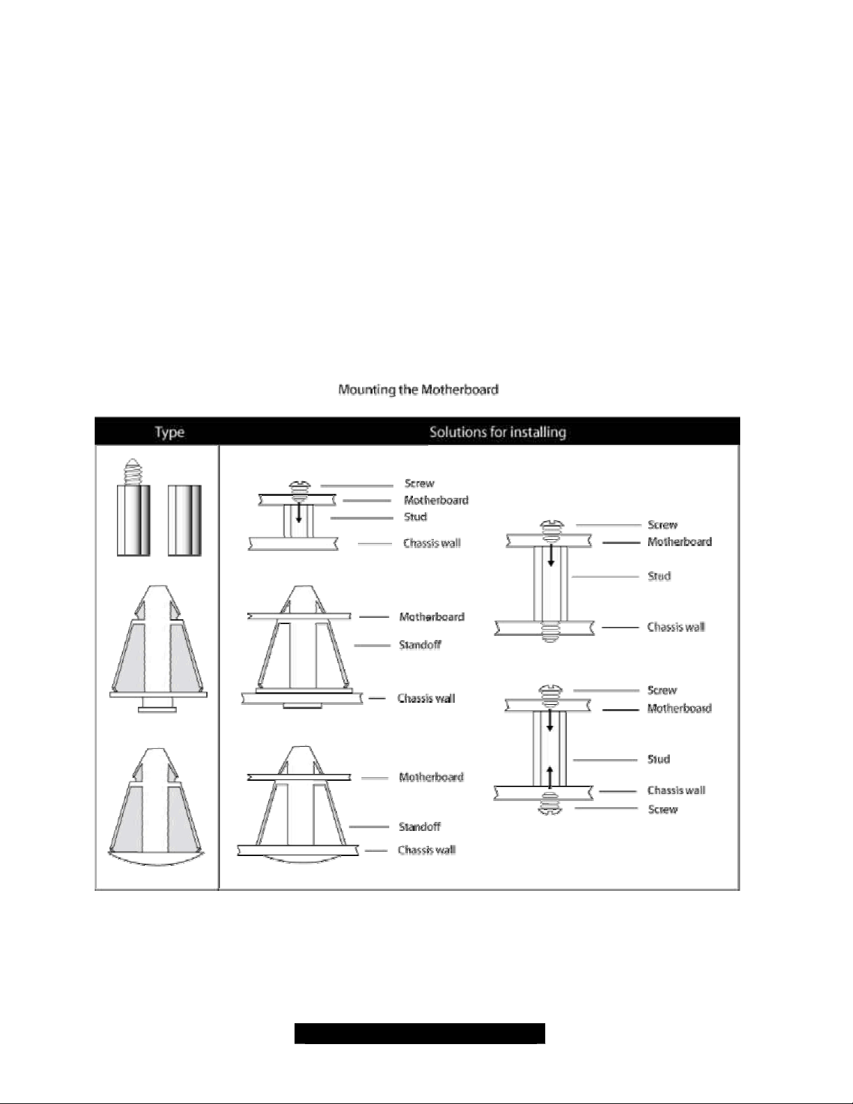
2.18 – Mounting the Motherboard
Before installing your motherboard, make sure your chassis has the necessary motherboard
support studs installed. These studs are usually metal and are gold in color. Usually, the chassis
manufacturer will pre- install the support studs.
- Memory Type: Tiger GC-SL S2727 only supports Registered DDR memory with ECC.
Non-Registered or non-ECC DDR memory modules are NOT supported. The board supports
single DIMM operation. Hence, the minimum memory module is one memory DIMM to allow
system to boot up.
- CPU Front-Side Bus Speed Match: The S2727 Tiger GC -SL memory frequency is
synchronized with both CPU and onboard memory controller front-side bus, which means the
memory module speed rate should match the CPU FSB. For example, with an Intel Xeon
533MHz Front-Side Bus (FSB) processor, the memory only supports DDR266/PC2100 Registered
ECC DIMM modules.
Below is a chart detailing what the most common motherboard studs look like and how they
should be installed.
TIP: Use metal studs if possible, as they hold the motherboard into place more securely than
plastic standoffs.
18
http://www.tyan.com
Page 19
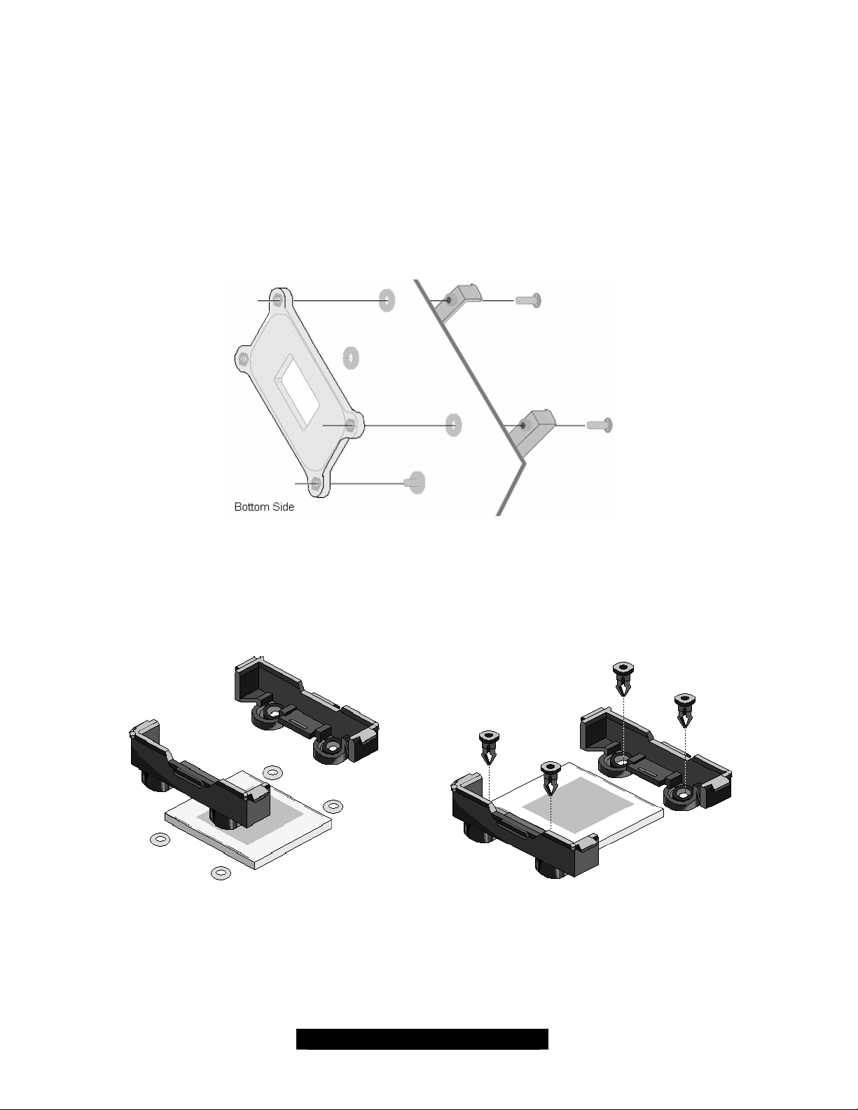
2.19 – Installation Guide of Xeon Processor Reinforcement Kit (CPU Back-plates)
The processors heatsinks should be installed with the provided Xeon Processor Reinforcement
Kit. Follow this installation guide, before installing the processors.
1. Check the parts in the kit: two back-plates and 9 screws.
(Four screws for each plate and one spare screw.)
2. The back- plates must be installed prior to installing the motherboard into a chassis.
3. Ensure that the screws have firmly secured the motherboard between the CPU
heatsink retention bases and the back-plates.
The following diagrams will illustrate how to install the included heatsink retention modules:
1) Align the heatsink mounting bracket to the holes around the processor socket
2) Insert Black securing peg (use the screws instead and skip step 5, if install with the
CPU reinforcement kit) into bracket holes
3) Insert White locking peg into Black securing peg
4) Repeat process to mount all other brackets
19
http://www.tyan.com
Page 20
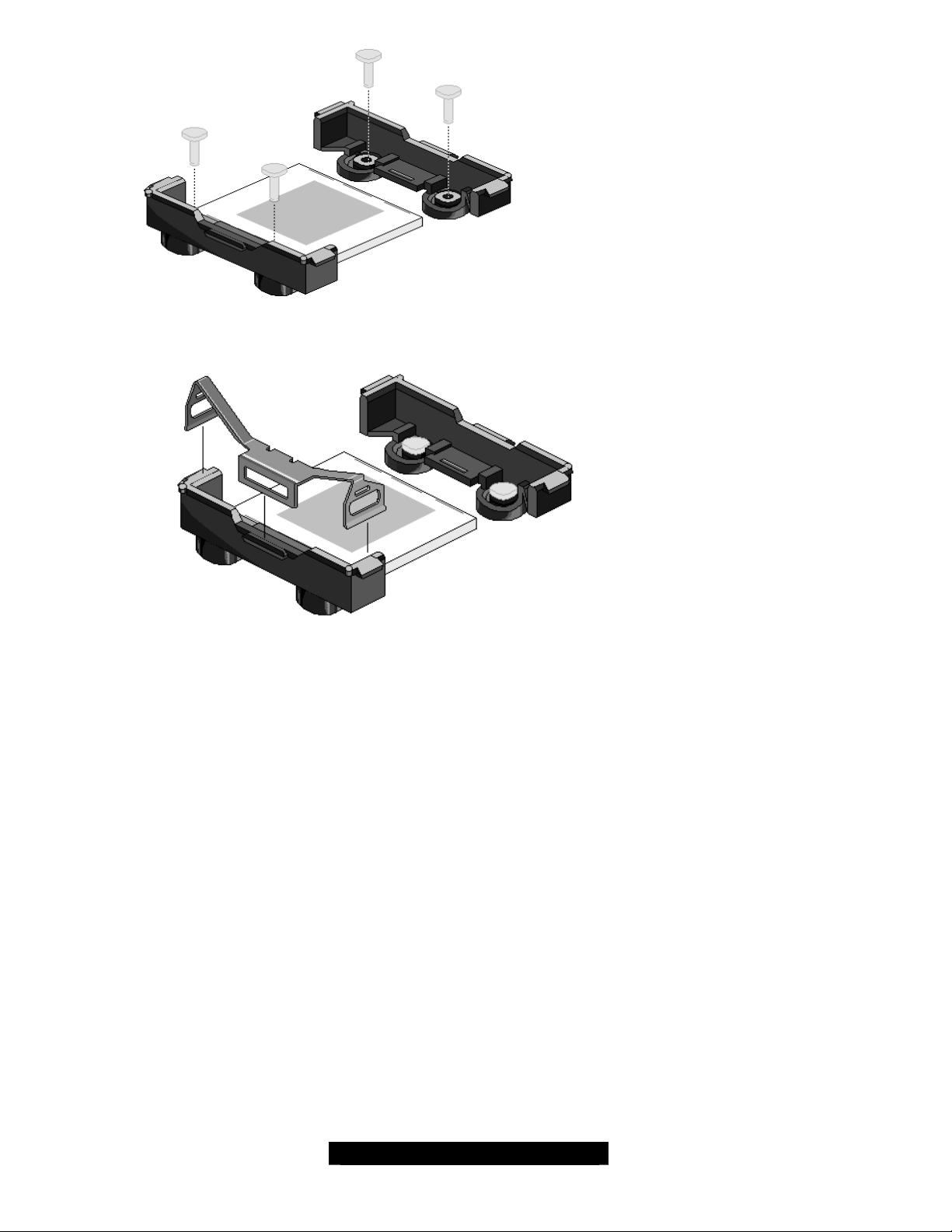
5) Seat heatsink between brackets on processor
6) Attach heatsink clips
20
http://www.tyan.com
Page 21
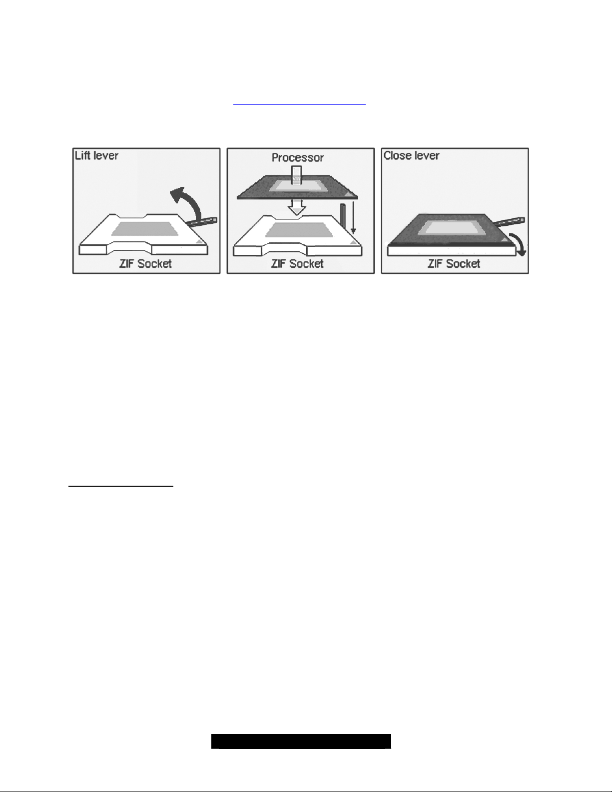
2.20 – Installing the Processor and Heatsink
Your Tiger GCSL S2727 supports the latest processor technologies from Intel. Check the
following page on TYAN’s website for latest processor support:
http://www.Tyan.com
The following diagrams will detail how to install your processor(s):
The processors you choose to use may not look exactly like the one pictured above, nor will the
socket look exactly the same. The diagram is provided as a visual guide to help you install socket
processors.
1. Lift the lever on the socket until it is approximately 130o or as far back as possible to the
socket.
2. Align the processor with the socket. There are keys underneath the processor just like
on memory modules to ensure that they insert the correct way.
3. Seat the processor firmly into the socket by gently pressing down until the processor
sits flush with the socket.
4. Place the socket lever back down until it snaps into place.
5. Your processor is installed.
6. Repeat these steps for the second processor if you are using two processors.
Heatsink Installation
After you are done installing the processor(s), you should proceed to installing their heatsinks.
Heatsinks will ensure that the processors do not overheat and continue to operate at maximum
performance for as long as you own them. Overheated processors may damage the motherboard.
Because there are many different types of heatsinks available from many different manufacturers,
a lot of them have their own method of installation. For the safest method of installation and
information on choosing the appropriate heatsink, please refer to Intel’s website at
http://www.intel.com.
21
http://www.tyan.com
Page 22
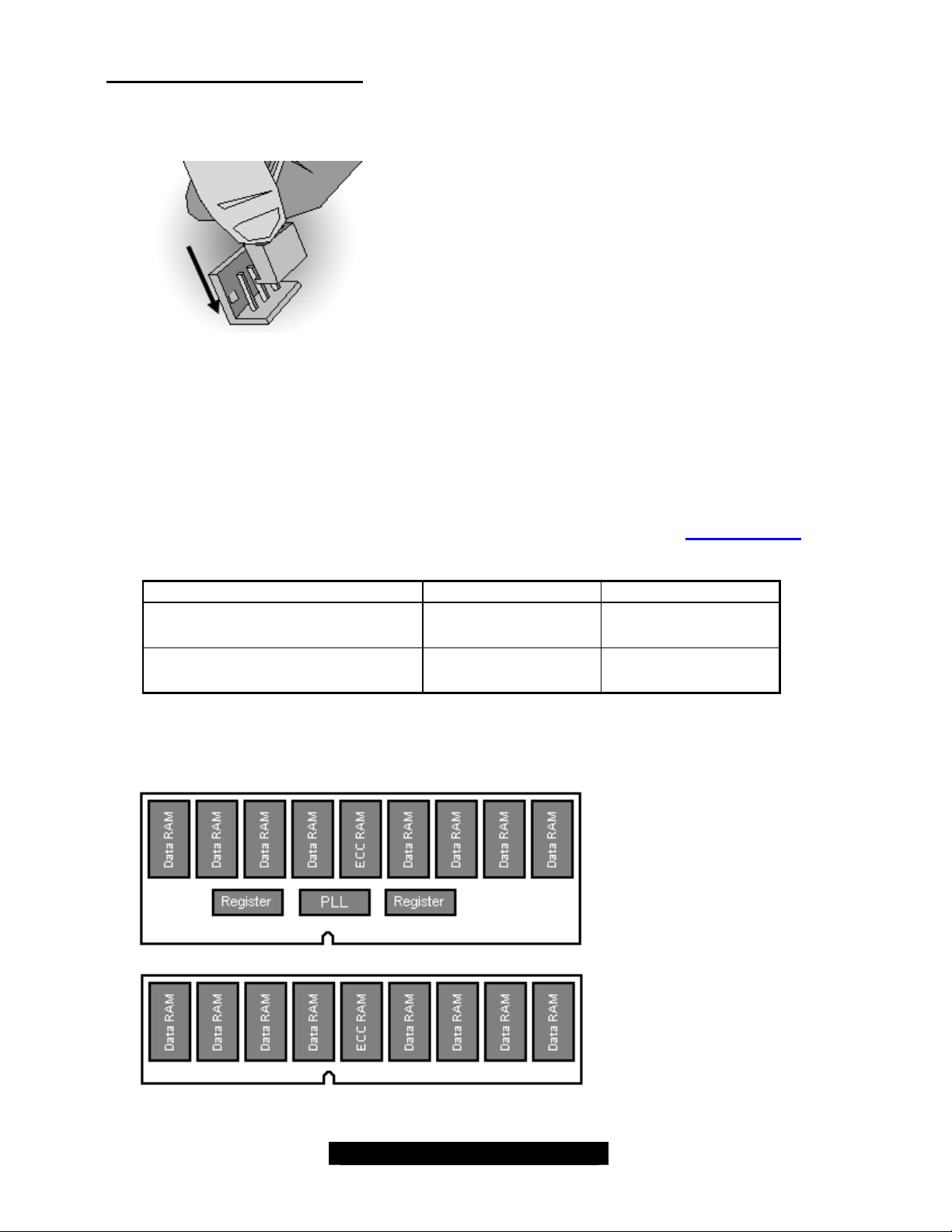
This diagram illustrates how to connect
Finishing Installing the Heatsink
After you finish installing the heatsink, attach the end wire of the fan (already be attached to the
heatsink) to the motherboard.
fans onto the motherboard.
After you’re finished installing all the fans you can now connect your drives (hard drives, CD- ROM
drives, etc.) to your motherboard.
2.21 – Installing the Memory
Before attempting to install any memory, make sure that the memory you have is compatible with
the motherboard as well as the processor. For example, while PC1600 DDR modules are
compatible with all DDR based motherboards, they will not work if you are required to run the
motherboard and processor buses at 533MHz. For this, PC2100 DDR (DDR266) modules are
required. For important memory information, please check Tyan’s web site at: www.tyan.com for
recommendations.
Processor DDR200 (PC1600) DDR266 (PC2100)
Xeon 400MHz FSB
Xeon 533MHz FSB
The following diagram shows the types of RAM modules you may encounter depending on your
board:
v
supported
X
unsupported
v
supported
v
supported
22
DDR Registered ECC
v supported
DDR Unbuffered ECC
X unsupported
http://www.tyan.com
Page 23
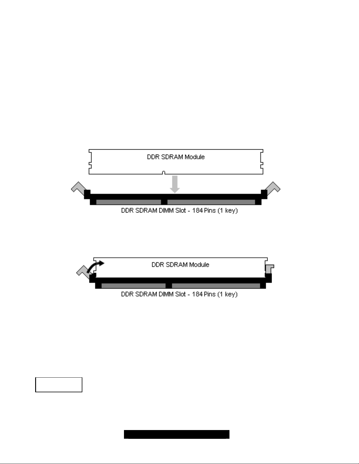
Here are a few key points to note before installing memory into your Tiger GC -SL:
• At least ONE Registered DDR module with ECC must be installed for the system
to turn on and POST (Power-On-Self-Test)
• 128MB, 256MB, 512MB and 1GB Registered PC2100/PC1600 DDR memory modules
are supported
• All installed memory will be automatically detected - no need to set any jumpers
• The Tiger GC-SL supports up to 4GB of memory
Memory Installation Procedure
When installing memory modules, make sure the modules align properly with the mem ory socket.
There should be keys (small indents) on your memory modules that fit according to the keys in the
memory socket. DDR modules and sockets have only one key, which is slightly near the center of
the module/socket. The SDR SDRAM modules and their sockets have two keys and will not insert
into DDR DIMM sockets. The method of installing memory modules is detailed in the following
diagrams.
Once the memory modules are firmly seated in the socket, two clamps on either side will close
and secure the module into the socket. Sometimes you may need to close the clamps manually.
To remove the memory module, simply push the clamps outwards until the memory module pops
up. Then simply remove the module.
TIP: When installing memory, a module may require a considerable amount of force to seat
properly, although this is very rare. To avoid bending and damaging your motherboard, place it on
its anti- static bag and onto a flat surface, and then proceed with memory installation.
NOTE
YOU MUST unplug the power connector to the motherboard before performing
system hardware changes, to avoid damaging the board or expansion device.
23
http://www.tyan.com
Page 24
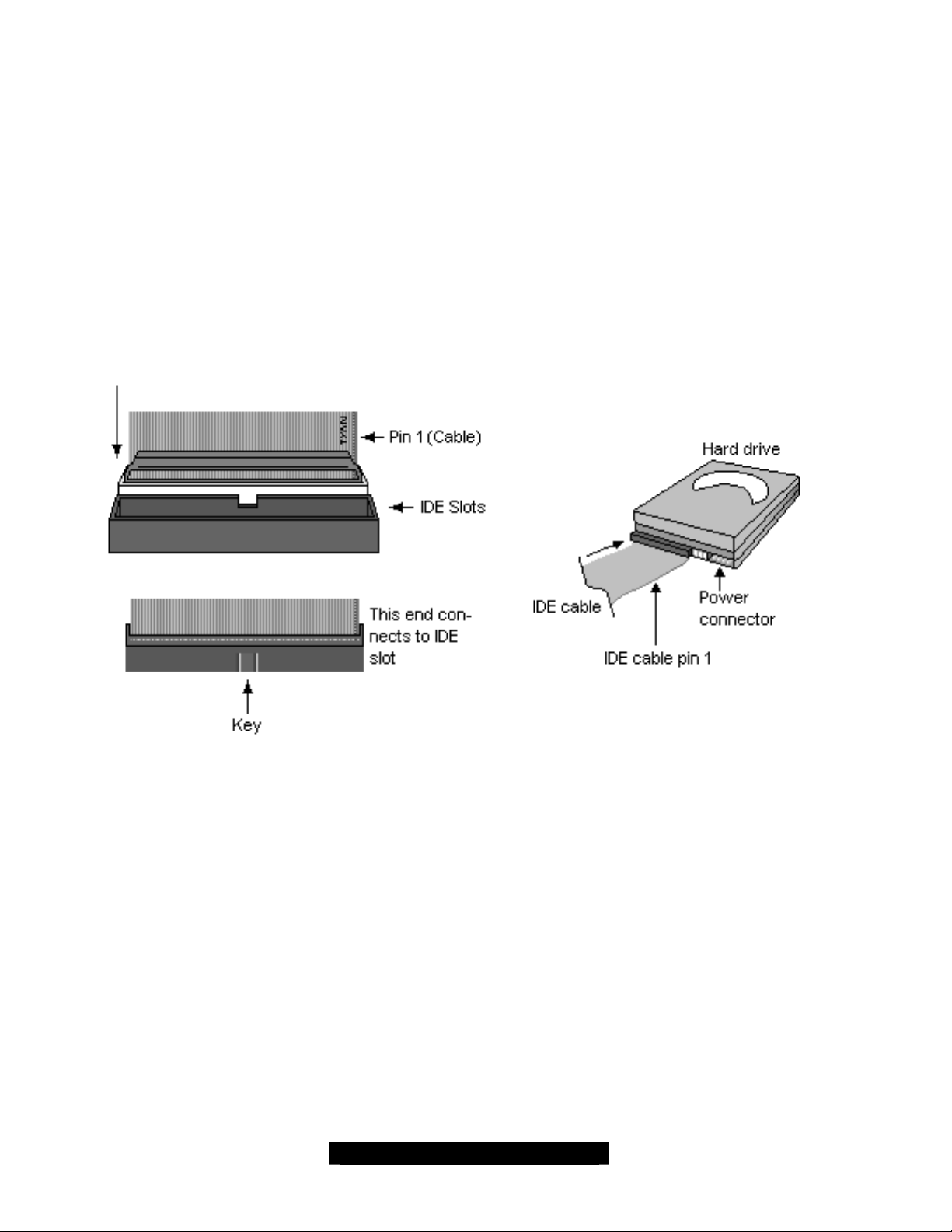
2.22 – Attaching Drive Cables
Attaching IDE drive cabling is simple. These cables are “keyed” to only allow them to be
connected in the correct manner. Tiger GCSL S2727 motherboard has three on-board IDE
channels and each channel can support two IDE/ATAPI drives.
The onboard three IDE connectors are designated with different colors:
The Primary IDE channel – Black color
§ S upports ATA -100/66/33 IDE and ATAPI compliant devices
The Secondary IDE channel – White color
§ S upports ATA -100/66/33 IDE and ATAPI compliant devices
The Tertiary IDE channel – Yellow color
§ S upports ATA -66/33 IDE and ATAPI compliant devices
Attaching IDE cables to the IDE connectors is illustrated below:
Simply plug in the BLUE END of the IDE cable into the motherboard IDE connector, and the other
end(s) into the drive(s). Each standard IDE cable has three connectors, two of which are closer
together. The BLUE connector that is furthest away from the other two is the end that connects to
the motherboard. The other two connectors are used to connect to drives.
TIP: Pin 1 on the IDE cable (usually designated by a colored wire) faces the dr ive’s power
connector.
24
http://www.tyan.com
Page 25
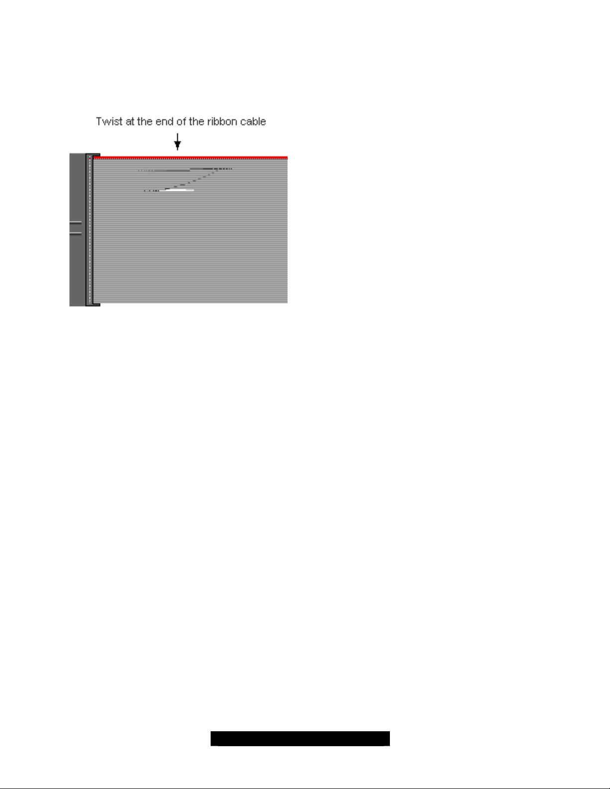
Floppy Drives
Attaching a floppy drive can be done in a similar manner to an IDE drive. Most of the current
floppy drives on the market require that the cable be installed with the colored stripe (pin- 1)
positioned next to the power connector. In most cases, there will be a key pin on the cable which
will force proper connection of the cable.
The first floppy drive (sometimes denoted as
A:) is usually attached to the end of the cable
with the twist in it. Drive B: is usually connected
to the second or third connector in the cable
(the second or third connector after you install
Drive A:).
Refer to your floppy drive’s installation
instructions (if available), or contact your dealer
if you are unsure about how to attach the
floppy drive(s). Remember, you can only have
2 floppy drives connected at any given time.
Below are some symptoms of incorrectly installed floppy drives:
§ Drive is not automatically detected
- Check if the floppy controller is enabled under the BIOS settings
- Verify that the floppy cable is installed correctly
- Verify that the floppy drive is working properly (i.e. try a new drive)
§ Drive Fail message at bootup
- Verify with another drive or cable
§ Drive does not power on
- Check power cable and cabling
- Check power supply
§ Drive activity light is constantly on
- Cable is on backwards
TIP: Pin 1 on the cable (usually designated by a colored wire) faces the drive’s power
connector.
25
http://www.tyan.com
Page 26
2.23 – Installing Add-In Cards
Before installing add-in cards, it’s helpful to know if they are fully compatible with your
motherboard. Simply find the appropriate slot for your add-in card and insert the card firmly. Do
not force any add-in cards (or anything else) into any slots if they won’t seat in place. It’s better to
try another slot or return the faulty card rather than damaging both the motherboard and the addin card.
TIP: It’s good practice to install add-in cards in a staggered manner, rather than directly adjacent
to each other. This allows air to more easily circulate within the chassis, providing improved
cooling for all installed devices.
NOTE
Before continuing onto the next section on connecting External Devices, make sure everything is
properly connected. Typically, jumpers and case wiring are the most common causes of
troubleshooting frustration,
YOU MUST UNPLUG the power connector to the motherboard before performing
system hardware changes, to avoid damaging the board or expansion device.
26
http://www.tyan.com
Page 27
2.24 – Connecting External Devices
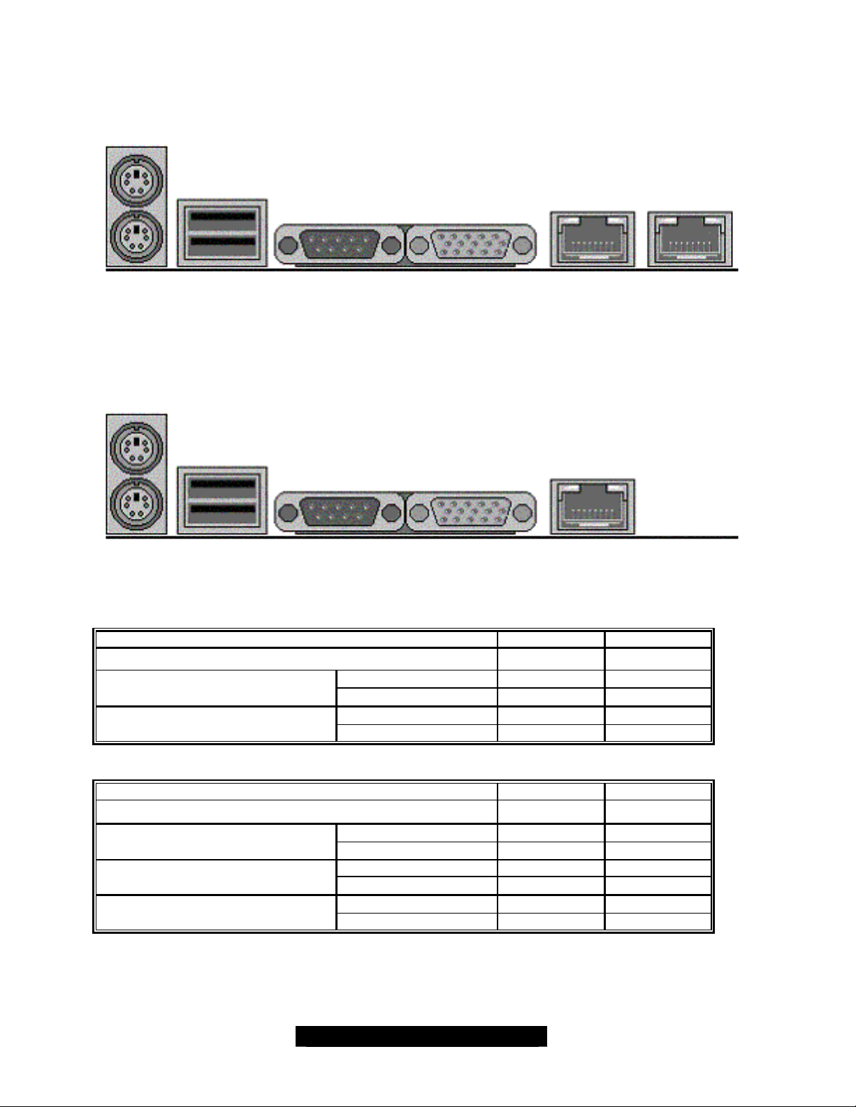
Connecting external devices to the motherboard is simple. Common external devices are
keyboards, mice, and printer cables. The following diagram will detail the ATX port stack for this
motherboard:
PS/2 USB COM1 VGA 10/100
LAN 1
S2727GNN Tiger GC -SL
10/100/1000
LAN2
PS/2 USB COM1 VGA 10/100
LAN 1
S2727GN Tiger GC-SL
10/100 LAN1
Network link not established
Linked at 10 Mbps
Linked at 100 Mbps
10/100/1000 LAN2
Network link not established
Linked at 10 Mbps
Linked at 100 Mbps
Linked at 1000 Mbps
Without Activity
With Activity
Without Activity
With Activity
Without Activity
With Activity
Without Activity
With Activity
Without Activity
With Activity
Left LED Right LED
Off Off
Off Green On
Off Green Blink
Yellow On Off
Yellow Blink Off
Left LED Right LED
Off Off
Off Green On
Off Green Blink
Yellow On Off
Yellow Blink Off
Yellow On Green On
Yellow Blink Green Blink
27
http://www.tyan.com
Page 28
2.25 – Installing the Power Supply
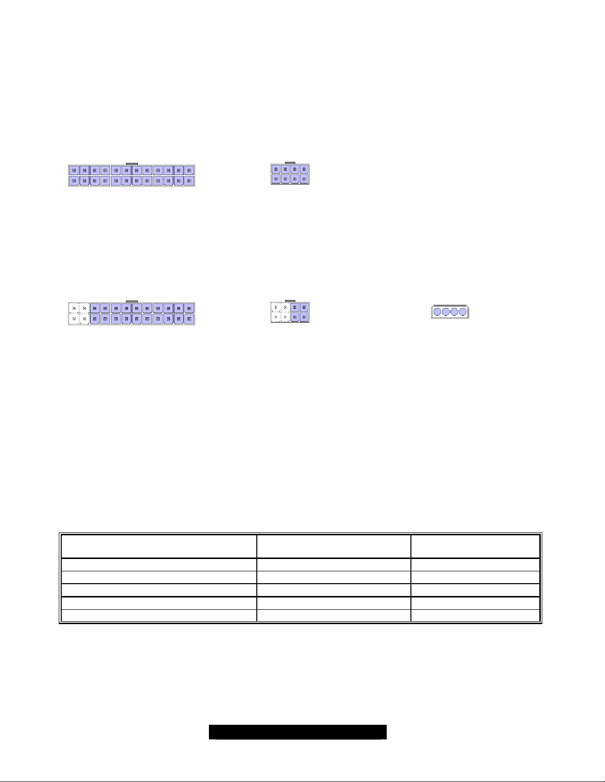
The Tiger GCSL S2727 is ATX12V and EPS12V compatible. Use one of the two combinations
below.
NOTE: You must remove the power cable from the electrical outlet before attaching the power
connectors to the board!
1. EPS 12V
+
EPS12V(24-pin) Connector
2. ATX 12V
• All 3 connectors need to be used for ATX12V power
• Make sure the power connector tab is at the top
• Plug in the 20-pin connector from the power supply on the right side of the 24-pin connector
• Plug in the 4-pin connector from the power supply on the right side of the 8-pin connector
EPS12V(8-pin) Connector
+
Plug into the right 20 pins
with the ATX12V (20-pin)
Connector
There are three power connectors on this motherboard. By default, this motherboard requires that
you have an ATX12V power supply that has the standard ATX-style 20-pin connector, as well as
an additional 4-pin square connector. The CPU power is provided by the onboard switching
voltage regulator, which is sourced by +12V power. This +12V CPU power source is from the
onboard 4-pin square connector and the 4- pin auxiliary drive power connector. The +12V power
on the 20- pin ATX power connector is for system board and separated from CPU +12V regulator
power source. Therefore, the CPU won't be powered neither connecting the 4-pin square ATX
12V power connector nor 4-pin auxiliary power connector.
In addition to the onboard 4- pin square connector for CPU regulator power, the onboard 4-pin
AUX drive power connector provides one additional +12V power wire.
Power connectors for CPU VRM
source
24-pin EPS12V connector 2 12 Amperes
8-pin EPS12V connector 4 24 Amperes
20-pin ATX/12Vconnector 1 6 Amperes
4-pin square ATX connector 2 12 Amperes
4-pin AUX drive power connectors 1 6 Amperes
Plug into the right 4 pins
with the ATX12V (4-pin)
Connector
Number of 12V power wires Max. Current Rating
+
AUX Drive Connector
28
http://www.tyan.com
Page 29

2.26 – Finishing Up
Congratulations on making it this far! You’re finished setting up the hardware aspect of your
computer. Before closing up your chassis, make sure that all cables and wires are connected
properly, especially IDE cables and most importantly, jumpers. You may have difficulty powering
on your system if the motherboard jumpers are not set correctly.
In the rare circumstance that you have experienced difficulty, even though the instructions herein
were followed, you can find help by asking your vendor for assistance. If they are not available for
assistance, please find setup information and documentation online at our website or by calling
your vendor’s support line.
29
http://www.tyan.com
Page 30

Chapter 3: BIOS
3.0 – BIOS Setup Utility
With the BIOS setup utility, you can modify BIOS settings and control the special features of your
computer. The setup utility uses a number of menus for making changes and turning the special
features on or off.
All menus are based on a typical system. The actual menus displayed on your
NOTE
To start the BIOS setup utility:
Main Advanced PCI/PnP Boot Chipset ACPI Security Exit
Item Specific Help
System Overview
AMI BIOS
Version 8.00.00
Build Date Jan/01/2003
Processor
Type Intel XEON CPU 3.xxGHz
Count 2
System Time [12:59:59]
System Date [01/01/2003]
F1 Help × Select Item -/+ Change Values F9 Setup Defaults
ESC Exit ÖSelect Menu Enter Select 4Sub-Menu F10 Save and Exit
To select an item
Use the left/right (Ö) arrow keys to make a selection
To display a sub-menu (A pointer “4” marks all sub menus)
Use the arrow keys to move the cursor to the sub menu you want. Then press <Enter>.
screen may be different and depend on the hardware and features installed in
your computer.
a. Turn on or reboot your system
b. Press <Del> to start BIOS setup utility
BIOS Setup Utility
<Tab>, <Shift-Tab>, or
<Enter> selects field
30
http://www.tyan.com
Page 31
3.1 – BIOS Menu Bar
The menu bar at the top of the windows lists these selections:
Main To configure basic system setups
Advanced To configure the CPU/IDE/Floppy/SuperIO features
PCI/PnP To configure the PCI/PnP features
Boot To configure system boot order
Chipset To configure the NB/SB chipset features
ACPI To configure power management features
Security To configure user and supervisor passwords
Exit To exit setup utility
NOTE
3.2 – BIOS Legend Bar
The chart describes the legend keys and their alternates:
Arrow keys Select a different menu
↑ or ↓ arrow keys Move cursor up/down
<Tab> or <Shift- Tab> Cycle cursor up/down
<Home> or <End> Move cursor to top/bottom of the window
<PgUp> or <PgDn> Move cursor to next/previous page
<F2> or <F3> Change screen color
Options written in bold type represent the BIOS setup default
Key Function
<ESC> Exit current menu
<-> Select the previous value/setting of the field
<+> Select the next value/setting of the field
<Enter> Execute command or select submenu
<F1> General help window
<F7> Discard change
<F8> Load failsafe defaults
<F9> Load the default configuration values of the menu
<F10> Save and exit
31
http://www.tyan.com
Page 32
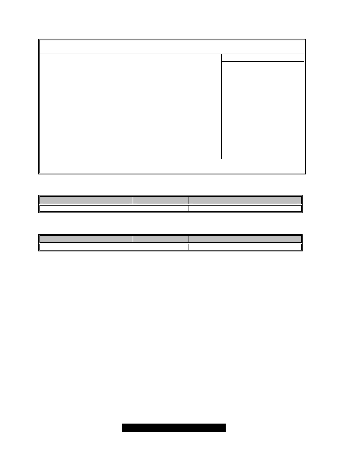
3.3 – BIOS Main Menu
BIOS Setup Utility
Main Advanced PCI/PnP Boot Chipset ACPI Security Exit
Item Specific Help
System Overview
AMI BIOS
Version 8.00.00
Build Date Jan/01/2003
Processor
Type Intel XEON CPU 3.xxGHz
Count 2
System Time [12:59:59]
System Date [01/01/2003]
F1 Help × Select Item -/+ Change Values F9 Setup Defaults
ESC Exit ÖSelect Menu Enter Select 4Sub-Menu F10 Save and Exit
3.3.1 – System Time
Feature Option Description
HH : MM : SS
3.3.2 – System Date
Feature Option Description
MM : DD : YYYY
---
---
Set the system time
Set the system date
<Tab>, <Shift-Tab>, or
<Enter> selects field
32
http://www.tyan.com
Page 33
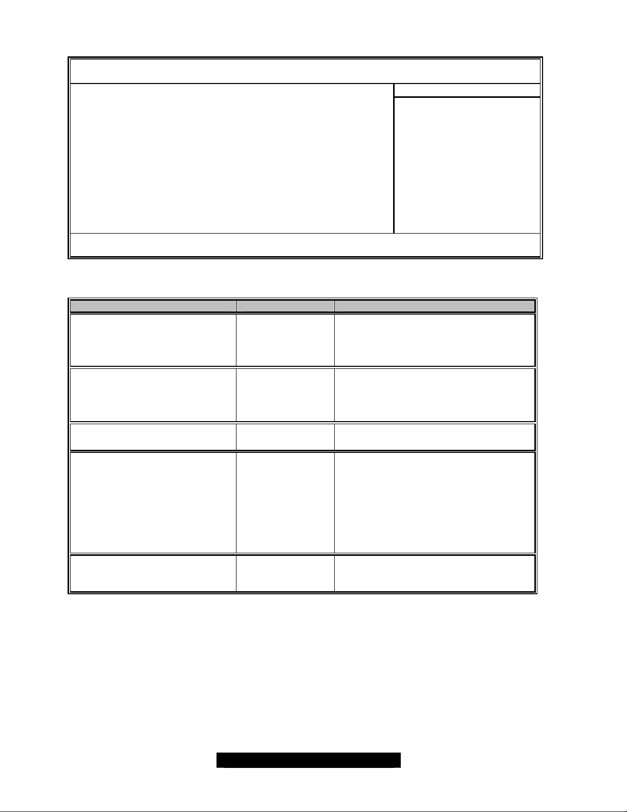
3.4 – BIOS Advanced Menu
BIOS Setup Utility
Main Advanced PCI/PnP Boot Chipset ACPI Security Exit
Item Specific Help
Advanced Setting
4CPU Configuration
4IDE Configuration
4Floppy Configuration
4Super I/O Configuration
4Remote Access Configuration
4USB Configuration
4System Health Monitor
4Watchdog Timer Configuration
F1 Help × Select Item -/+ Change Values F9 Setup Defaults
ESC Exit ÖSelect Menu Enter Select 4Sub-Menu F10 Save and Exit
3.4.1 – IDE Configuration Sub-Menu
Feature Option Description
Onboard PCI IDE Controller
Primary Master
Primary Slave
Secondary Master
Secondary Slave
Hard Disk Write Protect Enable
Disable
IDE Detect Time Out 0 sec
35 sec
ATA 80Pin Cable Detection Host & Device
Device
Both
Primary
Secondary
Disable
5 sec
10 sec
15 sec
20 sec
25 sec
30 sec
Host
This setting determines whether the
primary and secondary IDE channels
are activated.
This setting determines whether the
devices of primary and secondary IDE
channels are activated.
<Tab>, <Shift-Tab>, or
<Enter> selects field
33
http://www.tyan.com
Page 34
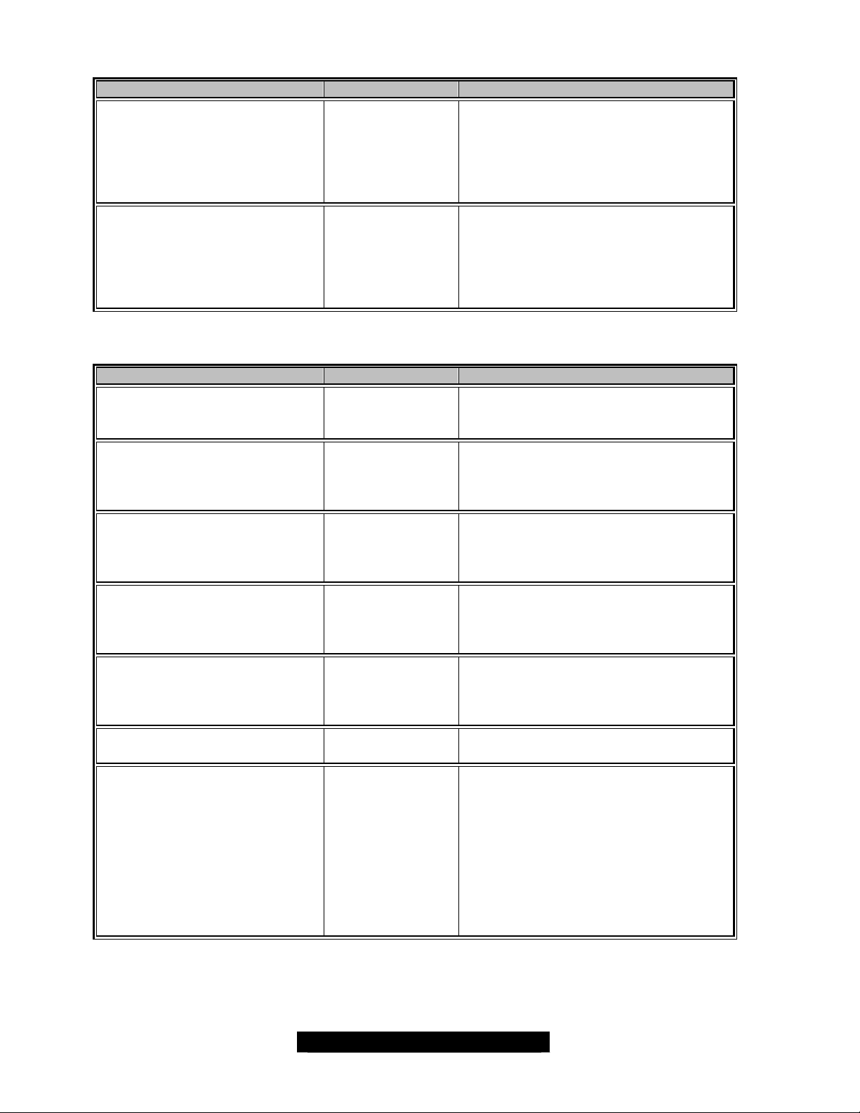
3.4.2 – Floppy Configuration Sub-Menu
Feature Option Description
Floppy A Disable
1.44 MB
Floppy B
3.4.3 – Super I/O Configuration Sub-Menu
Feature Option Description
Onboard Floppy Controller
360 KB
1.2 MB
720 KB
2.88 MB
Disable
360 KB
1.2 MB
720 KB
1.44 MB
2.88 MB
Enabled
Disabled
This setting determines selects the
type of the floppy disk drive installed
in system.
This setting determines selects the
type of the floppy disk drive installed
in system.
This setting determines whether the
floppy disk controller is activated
Serial Port 1 Address
Serial Port 2 Address
Parallel Port Address Disable
378
Parallel Port Mode
Parallel Port Interrupt
Power Lost Control
3F8/IRQ4
3E8/IRQ4
2E8/IRQ3
Disable
2F8/IRQ3
3E8/IRQ4
2E8/IRQ3
Disable
278
3BC
Normal
ECP
EPP
Bi-directional
IRQ7
IRQ5
Always Off
Always On
Last State
Enabled – To turn on the port
It requires entering a base I/O address
and an interrupt number
Disabled – To turn off the port
Enabled – To turn on the port
It requires entering a base I/O address
and an interrupt number
Disabled – To turn off the port
Enabled – To turn on the port
It requires entering a base I/O address
and an interrupt number
Disabled – To turn off the port
This setting specifies whether your
system will reboot after a power failure
or interrupt occurs.
Set to always off to leave the system
in the power off state.
Set to always on to leave the system
in the power on state.
Set to last state to restore the system
to the previous status before power
failure or interrupt occurred.
34
http://www.tyan.com
Page 35
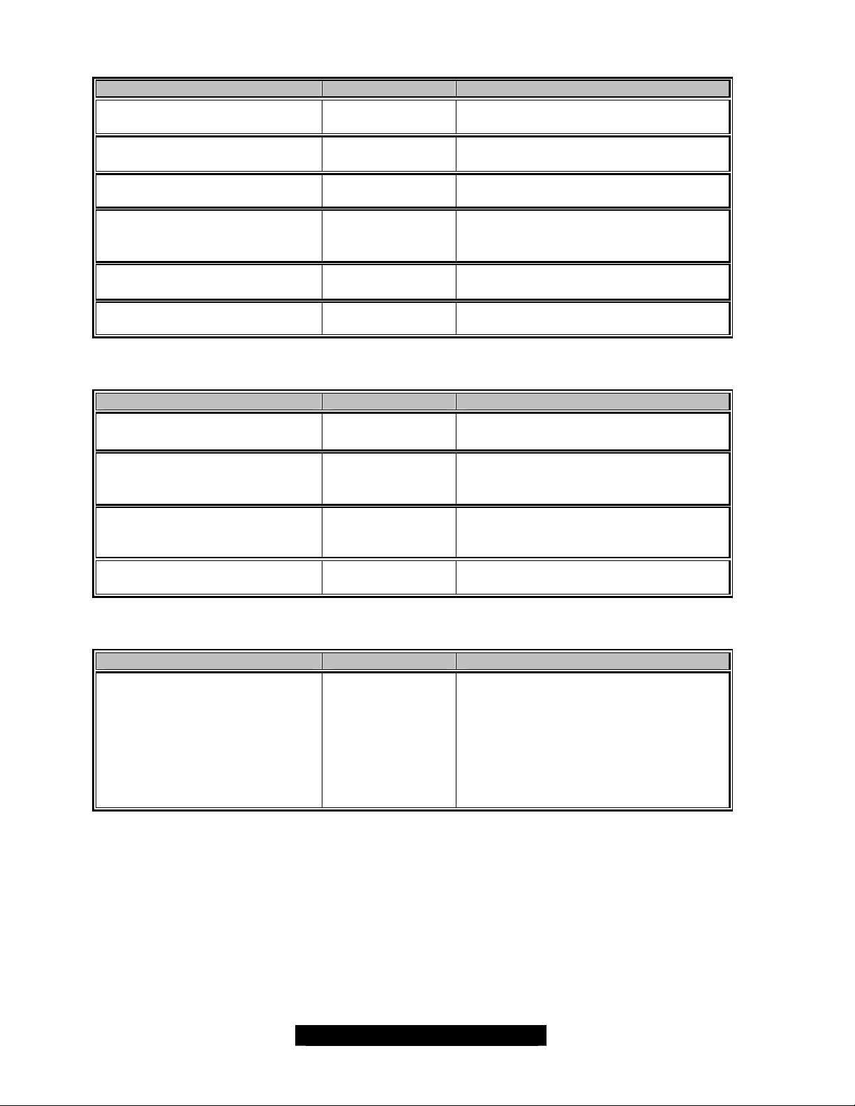
3.4.4 – Remote Access Configuration Sub-Menu
Feature Option Description
Remote Access
Terminal Type
Serial Port Number
Serial Port Mode
Flow Control
Post-Boot-Support
3.4.5 – USB Configuration Sub-Menu
Feature Option Description
USB Function
Legacy USB Support
USB ZIP Emulation Type
USB Beep Message
3.4.6 – Watchdog Timer Configuration Sub-Menu
Feature Option Description
Watchdog Timer
2 Minutes
5 Minutes
10 Minutes
15 Minutes
Serial
Disabled
ANSI
VT100
COM1
COM2
115200 8,n,1
57600 8,n,1
19200 8,n,1
None
Hardware
Disable
Enable
Enable
Disabled
Auto
Enable
Disable
Auto
Floppy
Hard Disk
Enable
Disabled
Disabled
The Watchdog Timer provides the
feature to automatic reboot the
system, when the OS locks up after
the user-defined period.
Under the normal system operations,
an application program, such as Tyan
TSM utility, resets the watchdog timer
periodically to prevent system reboot.
35
http://www.tyan.com
Page 36
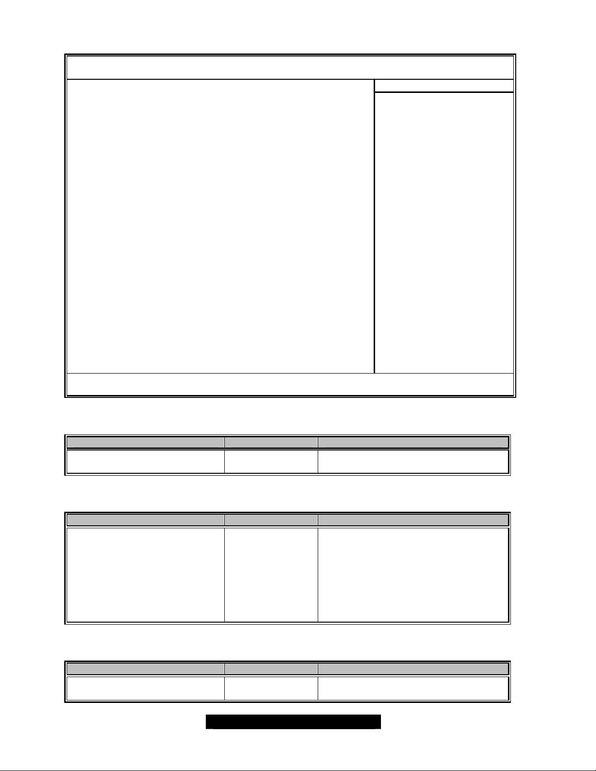
3.5 – BIOS PCI/PnP Menu
BIOS Setup Utility
Main Advanced PCI/PnP Boot Chipset ACPI Security Exit
Item Specific Help
4Plug & Play OS [Yes]
4PCI Latency Timer [64]
4Allocate IRQ to PCI VGA [Yes]
4PCI IDE Bus Master [Disable]
4Off-board PCI IDE Card [Auto]
4IRQ3 [Available]
4IRQ4 [Available]
4IRQ5 [Available]
4IRQ7 [Available]
4IRQ9 [Available]
4IRQ10 [Available]
4IRQ11 [Available]
4IRQ14 [Available]
4IRQ15 [Available]
4DMA Channel 0 [Available]
4DMA Channel 1 [Available]
4DMA Channel 3 [Available]
4DMA Channel 5 [Available]
4DMA Channel 6 [Available]
4DMA Channel 7 [Available]
4Reserved Memory Size [Disable]
F1 Help × Select Item -/+ Change Values F9 Setup Defaults
ESC Exit ÖSelect Menu Enter Select 4Sub-Menu F10 Save and Exit
3.5.1 – Plug & Play OS Sub -Menu
Feature Option Description
Plug & Play OS
3.5.2 – PCI Latency Timer Sub-Menu
Feature Option Description
PCI Latency Timer 32
64
3.5.3 – Allocate IRQ to PCI VGA Sub-Menu
Feature Option Description
Allocate IRQ to PCI VGA
Yes
No
96
128
160
192
224
248
Yes
No
Select the OS, which supports PnP.
This setting controls how long each
PCI device can hold the bus before
another PCI device takes over. When
set to higher values, every PCI device
can conduct transactions for a longer
time and thus improve the effective
PCI bandwidth.
For the onboard ATI Rage XL PCI
VGA.
<Tab>, <Shift-Tab>, or
<Enter> selects field
36
http://www.tyan.com
Page 37
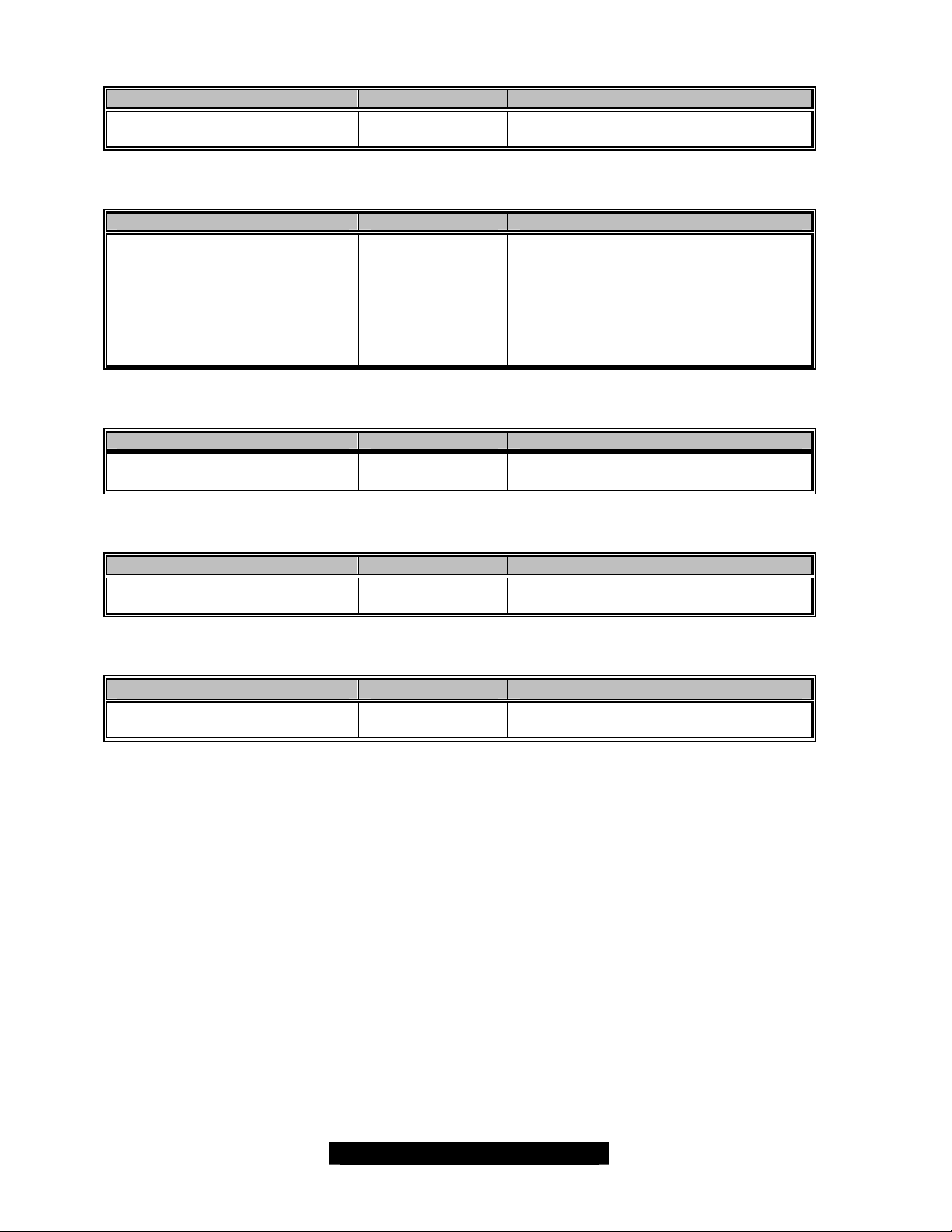
3.5.4 – PCI IDE Bus Master Sub-Menu
Feature Option Description
PCI IDE Bus Master Enabled
Disabled
3.5.5 – Off-board PCI IDE Card Sub-Menu
Feature Option Description
Off- board PCI IDE Card
3.5.6 – IRQ3~IRQ15 Sub -Menu
Feature Option Description
IRQ3~IRQ15
3.5.7 – DMA0~DMA7 Sub-Menu
Feature Option Description
DMA0~DMA7
3.5.8 – Reserved Memory Size Sub-Menu
Feature Option Description
Reserved Memory Size Enabled
Disabled
Auto
PCI Slot1
PCI Slot2
PCI Slot3
PCI Slot4
PCI Slot5
PCI Slot6
Available
Reserved
Available
Reserved
For a PCI IDE add-in card.
This setting provides firmware solution
for some special PCI IDE add- in cards.
37
http://www.tyan.com
Page 38
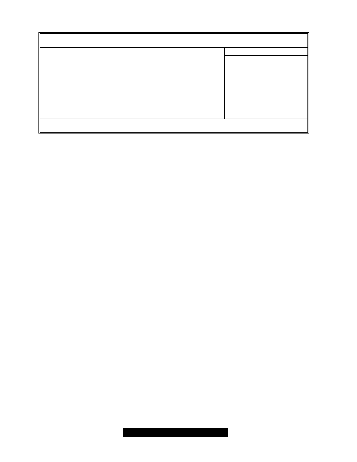
3.6 – BIOS Boot Menu
BIOS Setup Utility
Main Advanced PCI/PnP Boot Chipset ACPI Security Exit
Item Specific Help
4Boot Device Priority
4Hard Disk Devices
4Removable Disk Devices
4ATAPI Devices
F1 Help × Select Item -/+ Change Values F9 Setup Defaults
ESC Exit ÖSelect Menu Enter Select 4Sub-Menu F10 Save and Exit
3.6.1 – Boot Device Priority Sub-Menu
The boot menu will list all bootable devices. Arrange the priorities of all bootable devices by using
arrow keys and then pressing <Enter>.
<Tab>, <Shift-Tab>, or
<Enter> selects field
38
http://www.tyan.com
Page 39
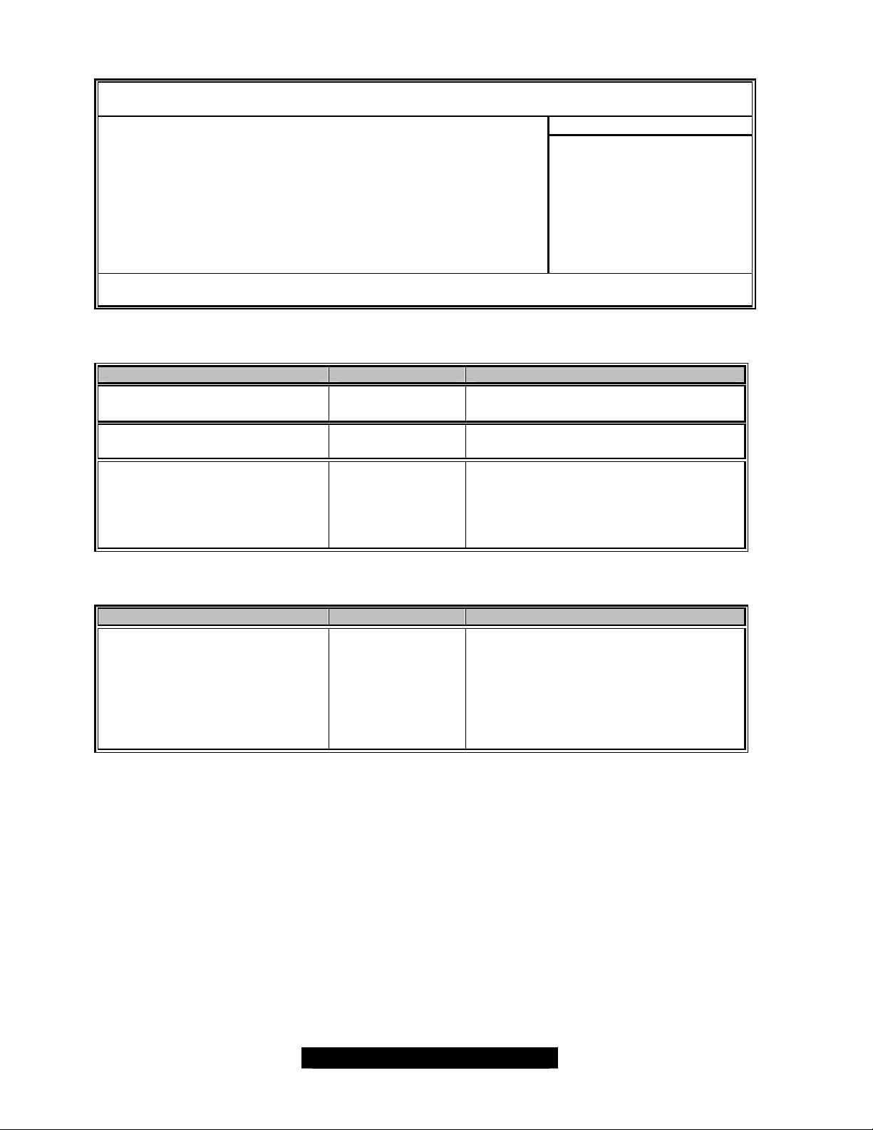
3.7 – BIOS Chipset Menu
BIOS Setup Utility
Main Advanced PCI/PnP Boot Chipset ACPI Security Exit
Item Specific Help
4NorthBridge Configuration
4SouthBridge Configuration
F1 Help × Select Item -/+ Change Values F9 Setup Defaults
ESC Exit ÖSelect Menu Enter Select 4Sub-Menu F10 Save and Exit
3.7.1 – NorthBridge Sub-Menu
Feature Option Description
Memory Timing Control
Memory CAS Latency 2
2.5
Hyper-Threading Tech Enable
Disable
3.7.2 – SouthBridge Sub-Menu
Feature Option Description
CSB6 Tertiary IDE channel Enable
Disable
Auto
Manual
This setting determines whether the
CPU Hyper-Threading is activated.
For operating systems that support
the Hyper-Threading functionality
such as Windows XP, 2K and RH-7.3.
The IDE devices on tertiary IDE
channel can be only recognized with
its device driver. For Windows 2K/XP,
OS recognizes it as a RAID controller
and should update the device drive by
using Windows built- in “Standard Dual
Channel PCI IDE Controller”.
<Tab>, <Shift-Tab>, or
<Enter> selects field
39
http://www.tyan.com
Page 40
3.8 – BIOS ACPI Menu
BIOS Setup Utility
Main Advanced PCI/PnP Boot Chipset ACPI Security Exit
Item Specific Help
4ACPI OS [Yes]
4Power Button Function [4 seconds delay]
F1 Help × Select Item -/+ Change Values F9 Setup Defaults
ESC Exit ÖSelect Menu Enter Select 4Sub-Menu F10 Save and Exit
3.8.1 – ACPI OS Sub -Menu
Feature Option Description
ACPI OS
3.8.2 – Power Button Function Sub-Menu
Feature Option Description
Power Button Function
Yes
No
4 seconds delay
Instant Off
For operating systems that support
the ACPI functionality such as XP, 2K
and Me.
<Tab>, <Shift-Tab>, or
<Enter> selects field
40
http://www.tyan.com
Page 41
3.9 – BIOS Security Menu
BIOS Setup Utility
Main Advanced PCI/PnP Boot Chipset ACPI Security Exit
Item Specific Help
4Change Supervisor Password
4Change User Password
4Clear User Password
F1 Help × Select Item -/+ Change Values F9 Setup Defaults
ESC Exit ÖSelect Menu Enter Select 4Sub-Menu F10 Save and Exit
<Tab>, <Shift-Tab>, or
<Enter> selects field
41
http://www.tyan.com
Page 42
3.10 – BIOS Exit Menu
BIOS Setup Utility
Main Advanced PCI/PnP Boot Chipset ACPI Security Exit
Item Specific Help
4Save Changes and Exit
4Discard Changes and Exit
4Discard Changes
4Load Optimal Defaults
4Load Failsafe Defaults
F1 Help × Select Item -/+ Change Values F9 Setup Defaults
ESC Exit ÖS elect Menu Enter Select 4Sub-Menu F10 Save and Exit
3.10.1 – Save Changes and Exit
Use this option to exit setup utility and re-boot.
All new selections you have made are stored into CMOS.
System will use the new settings to boot up.
3.10.2 – Discard Changes and Exit
Use this option to exit setup utility and re-boot.
All new selections you have made are not stored into CMOS.
System will use the old settings to boot up.
3.10.3 – Discard Changes
Use this option to restore all new setup values that you have made but not saved into CMOS.
3.10.4 – Load Optimal Defaults
Use this option to load all optimal default setup values.
Use this option when system CMOS values have been corrupted or modified incorrectly.
3.10.5 – Load Failsafe Defaults
Use this option to load all failsafe default setup values.
Use this option when system CMOS values have been corrupted or modified incorrectly.
<Tab>, <Shift-Tab>, or
<Enter> selects field
42
http://www.tyan.com
Page 43

Chapter 4: Diagnostics
Note: if you experience problems with setting up your system, always check the following things in
the following order:
CPU, Memory, Video
By checking these items, you will most likely find out what the problem might have been when
setting up your system. For more information on troubleshooting, check the Tyan website at:
http://www.tyan.com.
4.1 Beep Codes
Fatal errors, which halt the boot process, are communicated through a series of audible beeps.
For example, if the BIOS POST can initialize the video but an error occurs, an error message will
be displayed. If it cannot display the message, it will report the error as a series of beeps.
If you hear any beeps, please check your memory configuration, order, type, and check for faulty
modules. Please check our website for memory compatibility.
For S2727, we implement the following beep codes for memory diagnostics:
6 Short beeps = No memory inserted.
7 Short beeps = Non-Registered or non-ECC DIMMs inserted.
Before contacting your vendor or Tyan Technical Support, be sure that you note as much as you
can about the beep code length and order that you experience. Also, be ready with information
regarding add-in cards, drives and O/S to speed the support process and come to a quicker
solution.
43
http://www.tyan.com
Page 44

4.2 Flash Utility
Every BIOS file is unique for the motherboard it was designed for. For Flash Utilities, BIOS
downloads, and information on how to properly use the Flash Utility with your motherboard, please
check the Tyan web site: http://www.tyan.com/
The suggested method to update your BIOS is:
1. Download the latest BIOS from Tyan’s website at:
http://www.tyan.com/support/html/bios_support.html#Socket604
2. Copy the .rom file to a bootable floppy disk.
3. Copy the Amiflash.exe program to the floppy disk. You can find the latest approved
version on our website: http://www.tyan.com/support/html/flash_utilities.html
4. Boot to the floppy disk and flash the bios.
The correct DOS command to flash the BIOS on this board is as following example:
AMIFLASH 2727v101.rom /a /b /c
Where 2727v101.rom is the bios version you downloaded from our website (this is an example).
The space between the characters /a /b /c are very important. If you leave out the spaces only the
first parameter will be used.
Please note that you must use ALL the parameters to successfully update the BIOS!
For your reference:
/a = auto reboot after flash
/b= Program boot block
/c= Clear the CMOS
Please be aware that by flashing your BIOS, you agree that in the event of a BIOS
NOTE
flash failure, you must contact your dealer for a replacement BIOS. There are no
exceptions. Tyan does not have a policy for replacing BIOS chips directly with end
users. In no event will Tyan be held responsible for damages done by the end user.
44
http://www.tyan.com
Page 45

Appendix I: Glossary
ACPI (Advanced Configuration and Power Interface): a power management specification that
allows the operating system to control the amount of power distributed to the computer’s devices.
Devices not in use can be turned off, reducing unnecessary power expenditure.
AGP (Accelerated Graphics Port): an interface specifically designed for the demands of 3D
graphics applications. The 32- bit AGP channel directly links the graphics controller to the system
memory. While the channel runs at just 66MHz, it supports data transmission during both the
rising and falling ends of the clock cycle, yielding an effective speed of 133MHz.
ATAPI (AT Attachment Packet Interface): also known as IDE or ATA; a drive implementation
that includes the disk controller on the device itself. It allows CD- ROMs and tape drives to be
configured as master or slave devices, just like hard drives.
ATX: the form factor designed to replace the AT form factor. It improves on the AT design by
rotating the board 90 degrees, so that the IDE connectors are closer to the drive bays, and the
CPU is closer to the power supply and cooling fan. The keyboard, mouse, USB, serial, and
parallel ports are built-in.
Bandwidth: refers to carrying capacity. The greater the bandwidth, the more data the bus, phone
line, or other electrical path, can carry. Greater bandwidth, then, also results in greater speed.
BBS (BIOS Boot Specification): is a feature within the BIOS that creates, prioritizes, and
maintains a list of all Initial Program Load (IPL) devices, and then stores that list in NVRAM. IPL
devices have the ability to load and execute an O/S, as well as provide the ability to return to the
BIOS if the O/S load process fails for some reason. At that point, the next IPL device is called
upon to attempt loading of the O/S.
BIOS (Basic Input/Output System): the firmware that resides in the ROM chip, and provides the
basic instructions for controlling your computer’s hardware. Both the operating system and
application software use BIOS routines to ensure compatibility.
Buffer: a portion of RAM which is used to temporarily store data, usually from an application,
though it is also used when printing, and in most keyboard drivers. The CPU can manipulate data
in a buffer before copying it, all at once, to a disk drive. While this improves system performance --
- reading to or writing from a disk drive a single time is much faster than doing so repeatedly --there is also the possibility of losing your data should the system crash. Information stored in a
buffer is temporarily stored, not permanently saved.
Bus: a data pathway. The term is commonly used to refer to the connection between the
processor and system memory, and between the processor and AGP, PCI or ISA buses.
Bus mastering: allows peripheral devices and IDE controllers to access the system memory
without going through the CPU (similar to DMA channels).
Cache: a temporary storage area for data that will be needed often by an application. Using a
cache lowers data access times, since the needed information is stored in the SRAM instead of in
the slower DRAM. Note that the cache is also much smaller than your system memory: a typical
cache size is 512KB, while you may have as much as 4GB or more of system memory.
45
http://www.tyan.com
Page 46

Cache size : refers to the physical size of the cache. This should not be confused with the
cacheable area, which is the total amount of memory, which can be scanned by the system in
search of data to put into the cache. A typical setup would be a cache size of 512KB, and a
cacheable area of 512MB. In this case, up to 512KB of system memory is capable of being
cached. However, only 512KB of this memory will be in the cache at any given moment.
Closed and open jumpers: jumpers and jumper pins are active when they are “on” or “closed”,
and inactive when they are “off” or “open”.
CMOS (Complementary Metal-Oxide Semiconductor): chips that hold the basic startup
information for the BIOS.
COM port: another name for the serial port, which is called such because it transmits the eight
bits of a byte of data along one wire, and receives data on another single wire (that is, the data is
transmitted in serial form, one bit after another). Parallel ports transmit the bits of a byte on eight
different wires at the same time (that is, in parallel form, eight bits at the same time).
DDR (Double Data Rate): is a technology designed to double the clock speed of the memory. It
activates output on both the rising and falling edge of the system clock rather than on just the
rising edge, potentially doubling throughput.
DIMM (Dual In-line Memory Module): faster and more capacious form of RAM than SIMMs.
DIMM bank: sometimes called DIMM sockets, because the physical slot and the logical unit are
the same. That is, one DIMM module fits into one DIMM socket, which is capable of acting as a
memory bank.
DMA (Direct Memory Access): channels that are similar to IRQs. DMA channels allow hardware
devices (like soundcards or keyboards) to access the main memory without involving the CPU.
This frees up CPU resources for other tasks. As with IRQs, it is vital that you do not double up
devices on a single line. Plug-n-Play devices will take care of this for you.
Doze mode: in this mode, only the CPU’s speed is slowed.
DRAM (Dynamic RAM): widely available, very affordable form of RAM which will lose data if it is
not recharged regularly (every few milliseconds). This refresh requirement makes DRAM three to
ten times slower than non-recharged RAM such as SRAM.
ECC (Error Correction Code or Error Checking and Correcting): allows data to be checked for
errors during run- time. Errors can subsequently be corrected at the same time that they’re found.
EEPROM (Electrically Erasable Programmable ROM): also called Flash BIOS, is a ROM chip
which can, unlike normal ROM, be updated. This allows you to keep up with changes in the BIOS
programs without having to replace the BIOS chip. Tyan’s BIOS updates can be found at
http://www.tyan.com.
ESCD (Extended System Configuration Data): a format for storing information about Plug-nPlay devices in the system BIOS. This information helps properly configure the system each time
it boots.
Fault -tolerance: a term describing a system where one component can quickly be replaced
without causing a loss of service, such as in a RAID system.
Firmware: low-level software that controls the system hardware.
46
http://www.tyan.com
Page 47

Form factor: an industry term for the size, shape, power supply type, and external connector type
of the Personal Computer Board (PCB) or motherboard. The most common form factors in use
today are; ATX, microATX, FlexATX, Extended ATX, SSI EEB, and SSI MEB.
Global timer: onboard hardware timer, such as the Real -Time Clock (RTC).
Handshaking: a form of encryption. One system, typically the server, sends an encryption
scheme to another agent, typically a client. Thus, the client’s data is protected during transmittal to
the server.
HDD: stands for Hard Disk Drive, a type of fixed drive.
H-SYNC: controls the horizontal synchronization/properties of the monitor.
IC (Integrated Circuit): the common, formal name for a computer chip.
IDE (Integrated Device/Drive Electroni cs): a simple, self-contained HDD interface. It can handle
drives up to 8.4 GB in size. Almost all IDE drives sold today are a form of Enhanced IDE (EIDE),
with maximum capacity determined by the hardware controller.
IDE INT (IDE Interrupt): a hardware interrupt signal that goes to the IDE.
I/O (Input/Output): the connection between a computer and another device (mouse, keyboard,
etc.)
Initial Program Load (IPL): a feature built into BBS-compliant devices, describing those devices
as capable of loading and executing an O/S, as well as being able to provide control back to the
BIOS if the loading attempt fails.
IPL: see Initial Program Load.
IRQ (Interrupt Request): an electronic request that runs from a hardware device to the CPU. The
interrupt controller assigns priorities to incoming requests and delivers them to the CPU. It is
important that there is only one device hooked up to each IRQ line. Doubling up devices on IRQ
lines can cause problems. Plug- n-Play operating systems can take care of these details for you.
ISA (Industry Standard Architecture): a slower 8- or 16-bit bus (data pathway). The original IBM
PC, PC-XT, and PC-AT utilized these bus architectures.
Latency: the amount of time that one part of a system spends waiting for another part to catch up.
This is most common when the system sends data out to a peripheral device, and waits for the
peripheral to send data back (peripherals tend to be slower than onboard system components).
Mirroring: see RAID.
NVRAM: ROM and EEPROM are both examp les of Non-Volatile RAM, memory that holds its data
without power. DRAM, in contrast, is volatile.
OEM (Original Equipment Manufacturer): manufacturers that commonly package other
companies’ motherboards and hardware inside their chassis and sell them.
P arallel port: transmits the bits of a byte on eight different wires at the same time (that is, in
parallel form, eight bits at the same time).
PCI (Peripheral Component Interconnect): a 32 or 64-bit local bus (data pathway) which is
faster than the ISA bus. Local buses are those which operate within a single system (as opposed
to a network bus, which connects multiple systems).
47
http://www.tyan.com
Page 48

PCI PIO (PCI Programmable Input/Output) modes: the data transfer modes used by IDE drives.
These modes use the CPU for data transfer (in contrast, DMA channels do not). PCI refers to the
type of bus used by these modes to communicate with the CPU.
PCI-to-PCI bridge: allows you to connect multiple PCI devices onto one PCI bus.
Pipeline burst SRAM: a fast secondary cache. It is used as a secondary cache because SRAM
is slower than SDRAM, but usually larger. Data is cached first to the faster primary cache, and
then, when the primary cache is full, to the slower secondary cache.
Pipelining: improves system performance by allowing the CPU to begin executing a second
instruction before the first is completed. A pipeline can be likened to an assembly line, with a given
part of the pipeline repeatedly executing a set part of an operation on a series of instructions.
PM timers (Power Mana gement timers): software timers that count down the number of
seconds or minutes until the system times out and enters sleep, suspend, or doze mode.
PnP (Plug-n-Play): a design standard that has become ascendant in the industry. Plug- n-Play
devices require little set- up to use. Novice end users can simply plug them into a computer that is
running on a Plug-n-Play aware operating system (such as Windows 98/Me/XP), and go to work.
Devices and operating systems that are not Plug-n-Play require you to reconfigure your system
each time you add or change any part of your hardware.
PXE (Preboot Execution Environment): one of four components that together make up the
Wired for Management 2.0 baseline specification. PXE was designed to define a standard set of
preboot protocol services within a client, towards the goal of allowing networked-based booting to
boot using industry standard protocols.
RAID (Redundant Array of Independent/Inexpensive Disks): a way for the same data to be
stored in different places on many hard drives. By using this method, the data is stored
redundantly, also the multiple hard drives will appear as a single drive to the O/S. RAID Level 0 is
is known as striping, where data is striped (or overlapped) across multiple hard drives, but offers
no fault-tolerance. RAID Level 1 is known as mirroring, which stores the data within at least two
hard drives, but does not stripe. RAID Level 1 also allows for faster access time and faulttolerance, since either hard drive can be read at the same time. RAID Level 0+1 features both
striping and mirroring, providing fault-tolerance, striping, and faster access, all at the same time.
RAM (Random Access Memory): technically refers to a type of memory where any byte can be
accessed without touching the adjacent data, is often used to refer to the system’s main memory.
This memory is available to any program running on the computer.
ROM (Read-Only Memory): a storage chip which contains the BIOS; the basic instructions
required to boot the computer and start up the operating system.
SDRAM (Synchronous Dynamic RAM): called as such because it can keep two sets of memory
addresses open simultaneously. By transferring data alternately from one set of addresses and
then the other, SDRAM cuts down on the delays asso ciated with non-synchronous RAM, which
must close one address bank before opening the next.
Serial port: called as such because it transmits the eight bits of a byte of data along one wire, and
receives data on another single wire (that is, the data is transmitted in serial form, one bit after
another).
Sleep/Suspend mode: in this mode, all devices except the CPU shut down.
48
http://www.tyan.com
Page 49

SRAM (Static RAM): unlike DRAM, this type of RAM does not need to be refreshed in order to
prevent data loss. Thus, it is faster and more expensive.
SSI (Server System Infrastructure): Industry design specification for server baseboards and
systems. Encompasses full-AT-sized boards and related integrated items.
Standby mode: in this mode, the video and hard drives shut down; all other devices continue to
operate normally.
Striping: see RAID
UltraDMA- 33/66/100/133 (aka ATA-133/100/66/33): a fast version of the original DMA channel.
UltraDMA is also called UltraATA. Without a proper UltraDMA controller, your system cannot take
advantage of higher data transfer rates of the new UltraDMA/UltraATA hard drives.
USB (Universal Serial Bus): a versatile port. This one port type can function as a serial, parallel,
mouse, keyboard or joystick port. It is fast enough to support video transfer, and is capable of
supporting up to 127 daisy-chained peripheral devices.
VGA (Video Graphics Array): the PC video display standard
V- SYNC: controls the vertical scanning properties of the monitor.
ZIF Socket (Zero Insertion Force socket): these sockets make it possible to insert CPUs without
damaging the sensitive CPU pins. The CPU is lightly placed in an open ZIF socket, and a lever is
pulled down. This shifts the processor over and down, guiding into the board and locking it into
place.
49
http://www.tyan.com
Page 50

Appendix II: SMDC Information
Tyan Server Management Daughter Card (SMDC) is a powerful yet cost-efficient solution for
high-end server management hardware packages. Tyan’s goal is to provide remote system
monitoring and control even when the operating system is absence or simply fails. This
empowers Tyan’s server board with advanced industrial-standard features.
Tyan SMDC is a snap -in card that provides essential server management solution. It enables
any IT Manager by providing multi-interfaces to access the hardware remotely and perform
monitor, control and diagnose activities effectively.
Tyan SMDC is powered by an intelligent controller known as Baseboard Management Control
(BMC). BMC is a standalone mini-CPU and runs on its own Real Time Operating Syste m
(RTOS) to complete all different kinds of tasks. Backed by QLogic’s ARM7 technology, IT
manager can rest assure his server machines are always taken care.
Tyan SMDC is not a peripheral card. Unlike regular peripheral card such as AGP card,
Network card or SCSI card, SMDC does not require any hardware specific driver. As long as
a standby power comes into the system, SMDC will begin looking after the system.
Tyan SMDC provides diversified methods to communicate with the hardware. IT manager has
the flexibility to choose among Keyboard Controller Style (KCS), Block Transfer (BT) style,
Intelligent Chassis Management Bus (ICMB), Intelligent Platform Management Bus (IPMB),
Emergency Management Port (EMP) and standard IPMI-Over-LAN communication as defined
in latest IPMI 1.5 specification.
Tyan SMDC is compatible with all IPMI -compliance software as well as Tyan System
Operator™ (TSO) software package.
By adding SMDC, Tyan’s server board becomes a highly manageable and IPMI compatible
system with all the advanced features suggesting in IPMI Spec.
More detailed information on Tyan’s SMDC card can be found on our website:
Http://www.Tyan.com
50
http://www.tyan.com
Page 51
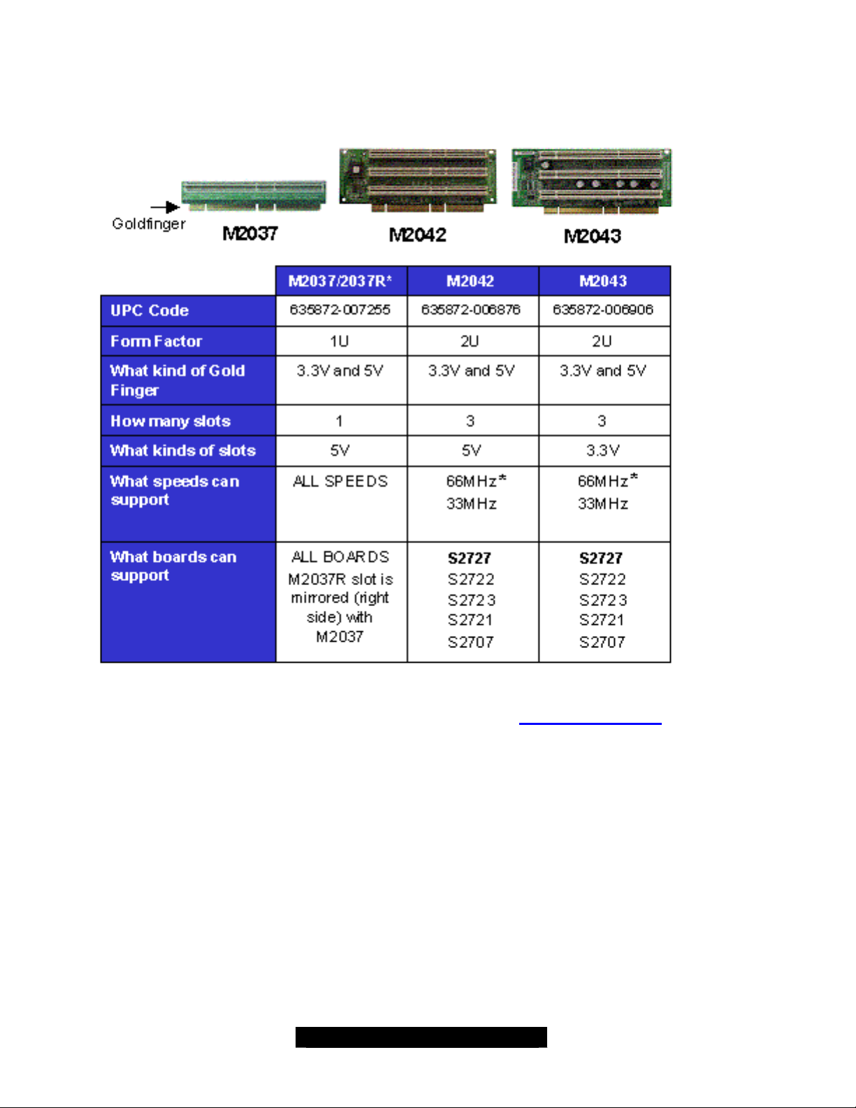
Appendix III: S2727 With Tyan Riser Cards
* S2727 supports 64/32- bit PCI bus at 33 MHz only.
Please check wi th your distributor for these riser cards or check http://www.etyan.com to purchase
the desired card(s).
51
http://www.tyan.com
Page 52

Technical Support
If a problem arises with your system, you should first turn to your dealer for assistance. Y our
system has most likely been configured by them, and they should have the best idea of what
hardware and software your system contains. Hence, they should be the most able to help.
Furthermore, if you purchased your system from a dealer near you, you ca n actually bring your
system to them to have it serviced, instead of having to do so yourself.
Help Resources:
1. See the beep codes section of this manual.
2. See the Tyan web site for FAQs, bulletins, driver updates, and other
information: http://www.tyan.com.
3. Contact your dealer for help BEFORE contacting Tyan.
4. Check the Tyan user group: alt.comp.periphs.mainboard.tyan
Returning Merchandise for Service
During the warranty period, contact your distributor or system vendor FIRST for any product
problems. This warranty only covers normal customer use and does not cover damages incurred
during shipping or failure due to the alteration, misuse, abuse, or improper maintenance of the
motherboard.
NOTE: A receipt or copy of your invoice marked with the date of purchase is required
before any warranty service can be rendered. You may obtain service by calling the
manufacturer for a Return Merchandise Authorization (RMA) number. The RMA number
should be prominently displayed on the outside of the shipping carton and the package
should be mailed prepaid. Tyan will pay to have the board shipped back to you.
52
http://www.tyan.com
Page 53
Notice for the USA
Compliance Information Statement (Declaration of Conformity Procedure) DoC
FCC Part 15: This device complies with part 15 of the FCC Rules
Operation is subject to the following conditions:
1) This device may not cause harmful interference, and
2) This device must accept any interference received including interference that may
cause undesired operation. If this equipment does cause harmful interference to radio
or television reception, which can be determined by turning the equipment off and on,
the user is encouraged to try one or more of the following measures:
• Reorient or relocate the receiving antenna.
• Increase the separation between the equipment and the receiver.
• Plug the equipment into an outlet on a circuit different from that of the
receiver.
• Consult the dealer on an experienced radio/television technician for help.
Notice for Canada
This apparatus complies with the Class B limits for radio interference as specified in the Canadian
Department of Communications Radio Interference Regulations. (Cet appareil est conforme aux
norms de Classe B d’interference radio tel que specifie par le Ministere Canadien des
Communications dans les reglements d’ineteference radio.)
Notice for Europe (CE Mark)
This product is in conformity with the Council Directive 89/336/EEC,
CAUTION: Lithium battery included with this board. Do not puncture, mutilate, or dispose of
battery in fire. Danger of explosion if battery is incorrectly replaced. Replace only with the same or
equivalent type recommended by manufacturer. Dispose of used battery according to
manufacturer instructions and in accordance with your local regulations.
92/31/EEC (EMC).
Document #: D1497 - 101
53
http://www.tyan.com
 Loading...