

Page 1

Thunder HEsl-T Manual
Revision 1.01
S2688
Copyright © TYAN Computer Corporation, 2001. All rights reserved. No part of this manual may be
reproduced or translated without prior written consent from TYAN Computer Corp.
All registered and unregistered trademarks and company names contained in this manual are
property of their respective owners including, but not limited to the following.
TYAN, Thunder HEsl-T S2688 are trademarks of TYAN Computer Corporation.
Intel, Intel Pentium, combinations thereof are trademarks of Intel Corporation.
ServerWorks, ServerSet III HE-SL, combinations thereof are trademarks of BC/ServerWorks, Corp.
Adaptec is a trademark of Adaptec, Inc.
AMI, AMI BIOS are trademarks of American Megatrends Inc.
Microsoft, Windows are trademarks of Microsoft Corporation.
IBM, PC, AT, PS/2 are trademarks of IBM Corporation.
Winbond is a trademark of Winbond Electronics Corporation.
Micronics is a trademark of Micronics Corporation.
Portable Document Format (PDF) is a trademark of Adobe Corporation.
Information contained in this document is furnished by TYAN Computer Corporation and has been
reviewed for accuracy and reliability prior to printing. TYAN assumes no liability whatsoever, and
disclaims any express or implied warranty, relating to sale and/or use of TYAN products including
liability or warranties relating to fitness for a particular purpose or merchantability. TYAN retains the
right to make changes to product descriptions and/or specifications at any time, without notice. In
no event will TYAN be held liable for any direct or indirect, incidental or consequential damage,
loss of use, loss of data or other malady resulting from errors or inaccuracies of information
contained in this document.
1
http://www.TYAN.com
Page 2

Table of Contents
Before you begin…
Chapter 1: Introduction
1.1 Congratulations
1.2 Hardware Specifications
1.3 Software Specifications
Chapter 2: Board Installation
2.1 Jumper Layout
2.2 Front Panel Connector
2.3 CMOS Reset
2.4 Force 33MHz Click for PCI Bus1
2.5 Force 33MHz Click for PCI Bus2
2.6 Host Bus Clock Frequency
2.7 CPU Core-to-Bus Multiplier
2.8 Add-in Drive Controller LED
2.9 External PC Speaker
2.10 Server Management Card
2.11 USB Port 2, 3 connectors
2.12 COM Port 2
2.13 LAN Activity LED
2.14 Mounting the motherboard
2.15 Installing Memory
2.16 Installing the CPU and Cooling Fan
2.17 Connecting IDE/Floppy Drives
2.18 Installing Add-in Cards
2.19 Connecting PS/2, USB, Serial
2.20 Connecting the Power Supply
2.21 You’re Done!
Chapter 3: BIOS Setup
3.1 Main Setup
3.2 Advanced
3.2a Super I/O Configuration
3.2b IDE Configuration
3.2c Floppy Configuration
3.2d Boot Settings Configuration
3.2e Onboard Device Configuration
3.2f Event Log Configuration
3.2g Chipset
3.2h PCIPnP
3.2i Power Management Setup
3.2j Power
3.2kSecurity
3.8 Exit
……………………………………………..Page 1
……………………………………………..Page 5
……………………………………………..Page 5
……………………………………………..Page 6
……………………………………………..Page 7
……………………………………………..Page 8
……………………………………………..Page 8
..……………………………………………Page 8
..……………………………………………Page 9
..……………………………………………Page 9
..……………………………………………Page 9
……………………………………………Page 10
……………………………………………Page 10
……………………………………………Page 10
……………………………………………Page 10
……………………………………………Page 10
……………………………………………Page 10
……………………………………………Page 11
……………………………………………Page 12
……………………………………………Page 13
……………………………………………Page 15
……………………………………………Page 17
……………………………………………Page 18
……………………………………………Page 18
……………………………………………Page 19
……………………………………………Page 20
……………………………………………Page 21
……………………………………………Page 21
……………………………………………Page 22
……………………………………………Page 22
……………………………………………Page 23
……………………………………………Page 23
……………………………………………Page 24
……………………………………………Page 24
……………………………………………Page 25
……………………………………………Page 25
……………………………………………Page 26
……………………………………………Page 26
……………………………………………Page 26
……………………………………………Page 26
Chapter 4: Installing the Hard Drives
SCSI Setup Section
Chapter 5: System Resources
5.1 Beep Codes
5.2 Flash Utility
……………………………………………Page 27
……………………………………………Page 29
……………………………………………Page 39
……………………………………………Page 39
2
http://www.TYAN.com
Page 3

Appendix I: Hardware Monitoring Information
……………………………………………Page 40
Appendix II: About Adaptec NightHawk
(2000S) Compatibility
Appendix III: Glossary
Technical Support
……………………………………………Page 41
……………………………………………Page 42
……………………………………………Page 47
3
http://www.TYAN.com
Page 4

Before you begin…
Check the box contents!
The retail motherboard package should contain the following:
1x Thunder HEsl-T motherboard
1x 34-Pin floppy drive cable
1x Ultra-DMA-100/66/33 IDE cable
1x Ultra160 SCSI cable (for optional SCSI if included onboard)
1x Cable set: 9-pin Serial
1x Thunder HEsl-T user’s manual
1x TYAN driver CD
1x Adaptec 7899W NT Ultra160 SCSI driver diskette (if optional SCSI included)
1x I/O shield with 2 LAN ports
If any of these items are missing, please contact your vendor/dealer for replacement before
continuing with the installation process.
4
http://www.TYAN.com
Page 5

Chapter 1: Introduction
1.1 Congratulations!
You are now the owner of the TYAN Thunder HEsl-T motherboard, the most reliable, high
performance motherboard for dual Pentium III processing. Designed to be portable as well as
flexible, the Thunder HEsl-T can fit into standard ATX chassis and 2U rackmount chassis. This
platform utilizes ServerWorks’ high-performance ServerSet III HE-SL chipset, enabling next
generation application and platform support. Intel Pentium III processors between 500MHz and
1.266GHz* are supported in single and dual configuration. *Please see TYAN’s website for
updates and information concerning CPU information and support:
http://www.tyan.com
This integrated performance board is supported in an ATX form factor. Features of the Thunder
HEsl-T include onboard UltraDMA-33 (Ultra160SCSI with onboard Adaptec controller) and
multiple boot options.
With both I/O and drive controller support onboard, dual 64-bit PCI slots provide upgrade solutions
for future add-in cards. Integrated 2D/3D graphics provided by the onboard ATI RAGE XL
controller enables ease of use into 2U and larger, chassis. Dual onboard LAN ports provide
connectivity without add-in overhead.
The Thunder HEsl-T supports up to 6GB of Registered ECC PC133 SDRAM.
Remember to visit TYAN’s Website at http://www.tyan.com. There you can find information on all
of TYAN’s products with FAQs, distributors list and BIOS setting explainations.
1.2 Hardware Specifications
Processor
• Dual PGA370 ZIF sockets
• Supports up to two Intel Pentium III
processors
• Supports Intel’s Pentium III Processor DP
• One onboard VRM (VRM 8.5) supports 2
CPUs
• Front-side bus support for 100/133MHz
Chipset
• ServerWorks ServerSet III HE-SL
• Integrated I/O APIC
• CSB5 south bridge
• CIOB north bridge
• National 87417 Super I/O ASIC
Memory
• Four 3.3v 168-pin DIMM sockets
• Supports up to 6GB of Registered
PC133/100 SDRAM
• Supports ECC (72-bit) memory
http://www.TYAN.com
Integrated LAN
• Dual Intel 82559 LAN controllers
• 10/100Mbps max data rate per controller
Integrated 2D/3D Graphics
• ATI RAGE XL graphics controller
• 4MB frame buffer (SDRAM)
• Standard 15-pin analog VGA port
Integrated SCSI (manufacturing option)
• Adaptec AIC-7899W controller
• Dual-channel Ultra160 SCSI support
• 160MB/sec max data throughput per
channel
• Supports up to 4 LVD SCSI devices per
channel
Hardware Monitoring
• Winbond W83782D hardware monitoring
ASIC
• CPU Temp, voltage and fan monitoring
5
Page 6

Expansion Slots
• 4 64-bit/66MHz (three 5v, one 3.3v) PCI
slots
• 2 32-bit/33MHz PCI slots
Integrated PCI IDE
• Dual-channel master mode
• Up to four E-IDE drives
• Support for DMA/ATAPI devices
Integrated I/O
• One floppy connector supports up to two
drives (second one via optional slim FD
connector)
• Two 9-pin 16550-based serial ports (one via
optional cable)
• One 25-pin SPP/ECP/EPP parallel port (via
optional cable)
• Four USB ports (two via optional cable)
• PS/2 keyboard and mouse ports
1.3 Software Specifications
OS Windows NT/2000
BIOS
• AMI 4Mb BIOS Flash ROM
• Auto-configure IDE drive types
• Multiple boot options
• DMI 2.0 compliant
Form Factor
• ATX footprint (12” x 9.6”, 304.8mm x
243.84mm
• One 20-pin ATX power connector
• One Serial port and one VGA port
• Stacked USB (two) ports
• Side-by-side LAN (two) ports
• Stacked keyboard and mouse ports
Regulatory
• FCC DoC (declaration of Conformity)
• European Community of CE (declaration of
Conformity)
6
http://www.TYAN.com
Page 7

Chapter 2: Board Installation
Installation
You are now ready to install your motherboard. The mounting hole pattern of the Thunder HEsl-T
matches the ATX system board specifications. Your chassis should support a standard ATX
motherboard form factor.
How to install our products right… the first time
The first thing you should do is read this user’s manual. It contains important information which will
make configuration and setup much easier. Here are some precautions you should take when
installing your motherboard:
(1) Ground yourself properly before removing your motherboard from the antistatic bag.
Unplug the power from your computer power supply and then touch the power supply.
For the safest conditions, TYAN recommends wearing a static safety wrist strap.
(2) Hold the motherboard by its edges and do not touch the bottom of the board.
(3) Avoid touching the motherboard components, IC chips, connectors, and leads.
(4) Avoid touching memory module contacts and IC chips
(5) Place the motherboard on a grounded antistatic surface or on the antistatic bag from
which it came in.
Having reviewed the precautions above, the next step is to take the motherboard out of the
cardboard box and static bag, hold it by its edges and place it on a grounded antistatic surface,
component side up. Inspect the board for damage.
NOTE DO NOT APPLY POWER TO THE BOARD IF IT HAS BEEN DAMAGED
7
http://www.TYAN.com
Page 8

2.1 – Jumper Section
Pin outs for certain connectors are available on the TYAN website: http://www.TYAN.com
2.2 – Front Panel Connector (J26)
17 15 13 11 9 7 5 3 1
18 16 14 12 10 8 6 4 2
1,3: HD LED
2,4: Power LED
5,7: Reset Switch
6,8: Power Switch
2.3 – CMOS Reset (JP8)
1 2
1,2: Connect these two pins together to reset the CMOS settings in case an incorrect
setting causes system instability or you have forgotten your system/setup password.
- Power off the system and disconnect the power supply.
- Close pins 1 and 2 on JP8
- Wait about 5 seconds
- Open pins 1 and 2 on JP8
- Reconnect the power supply and power on the system
2.4 – Force 33MHz Click for PCI Bus 1 (JP12)
1 2
Closed: All devices on PCI Bus1 (slots J31, J32, J33) will run at 33MHz Only.
Open (default): PCI Bus1 can run at 66MHz or 33MHz. Actual speed is determined
by the PCI card(s) plugged into J31/J32/J33. If any card is only 33MHz capable, all
cards in Bus1 will run at 33MHz. If all cards support 66MHz, or if no cards are
installed, then Bus1 will run at 66MHz.
http://www.TYAN.com
8
Page 9
2.5 – Force 33MHz Click for PCI Bus 2 (JP13)
1 2 Closed: All devices on PCI Bus2 (slots J35 and onboard SCSI) will run at 33MHz
2.6 – Host Bus (FSB) Clock Frequency Select (JP5)
2.7– CPU Core-to-Bus Frequency Multiplier Select (JP1-4)
These jumpers allow you to adjust the processor core multiplier. However, retail processors will
not allow multiplier adjustment.
JP1 JP2 JP3 JP4
Only.
Open (default): PCI Bus1 can run at 66MHz or 33MHz. Actual speed is determined
by the PCI card plugged into J33. If any card is only 33MHz capable, all cards in Bus1
will run at 33MHz. If all cards support 66MHz, or if no cards are installed, then Bus1
will run at 66MHz.
Closed: Host Bus clock frequency is fixed at 100 MHz, regardless of processor type.
1
Use this setting to force Host Bus clock to 100 MHz when using 133 MHz FSB
2
CPU(s).
Open (default): Host Bus clock frequency is determined by the type of processor(s)
installed. For CPUs that support 133 MHz Front Side Bus (FSB), Host Bus clock will
be automatically set at 133 MHz, but can be over-ridden to 100 MHz if JP5 is closed.
For CPUs that are only capable of operating at 100MHz FSB, Host Bus frequency will
be auto-configured to 100MHz, and 133 MHz is NOT possible.
JP1 JP2 JP3 JP4 Ratio
Open
Short
Short
Open
Open
Short
Short
Open
Open
Short
Open
Open
Short
Short
Short
Open
Short
Open
Open
Short
Open
Open
Open
Short
Short
Short
Short
Open
Short
Short
Short
Open
Open
Open
Open
Open
Open
Short
Open
Short
Open
Short
Open
Short
Open
Short
Short
Open
Open
Open
Short
Short
Open
Short
Open
Short
Short
Short
Short
Open
Open
Open
Open
Open
Short
Short
Short
Open
Short
Open
Short
Short
4.0x
4.0x
4.5x
5.0x
5.5x
6.0x
6.5x
7.0x
7.5x
8.0x
8.5x
9.0x
9.5x
10.0x
10.5x
11.0x
11.5x
12.0x
4.0x is the default setting.
Note: Whatever the multiplier is set to, the setting will apply to both CPUs. These settings only
affect non-retail (engineering sample, Q-spec) CPUs. For a production (S-spec) CPU, the
multiplier is fixed inside the CPU, and these jumpers will not have any affect regardless of their
setting.
9
http://www.TYAN.com
Page 10
2.8 – Add-in Drive Controller Activity LED (J27)
1
Connect your chassis front panel IDE LED to this jumper for activity monitoring of all
drives connected to the onboard IDE controllers.
2
2.9 – External PC Speaker (J28)
1
Connect your chassis speaker to these pins for speaker functionality.
2
3
4
2.10 – TYAN Server Management Daughter Card (SMDC) connector (J29)
You may use this connector for the server management card (purchased separately).
2.11 – USB Port 2, 3 Connectors (J24, J22)
1 1
2 2
3 3
4 4
5 5
JP24 JP22
You may use these connectors for front panel USB connectors if your chassis
allows.
2.12 – COM Port 2 (J18)
1 1
2 2
3 3
4 4
5
You may use the included COM2 cable in this connector if you wish to use the
second serial port.
2.13 LAN Activity LED (J9)
1
You may use the following pins for LAN activity LED.
2
Pins 1 and 2 are for LAN1 activity
3
Pins 3 and 4 are for LAN2 activity
4
10
http://www.TYAN.com
Page 11
2.14 Mounting the motherboard
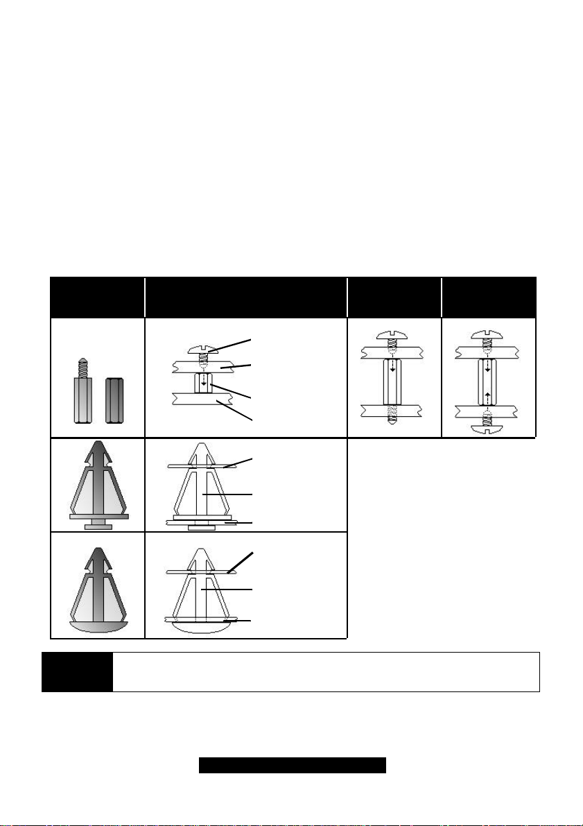
Your chassis may include mounting hardware. If mounting hardware was included, you can use
the following examples to help you in stalling your motherboard into the chassis.
If your chassis has the studs integrated into the chasses wall, then you would only need to use
screws (possibly included with your chassis) to install the motherboard. See examples (Figure 2.0,
shown below for more details.
If the chassis includes mounting hardware without the studs pre-installed, then you will need to
install the motherboard using the mounting hardware as shown in the examples below.
Remember not to over tighten any of the screws, or you may risk breaking internal traces in the
surrounding area, or damage the motherboard in some other way.
Other examples of how to install your motherboard using other hardware (that may or may not
have been included with your chassis) are shown below.
One solution for installing motherboardType of hardware Another solution Another solution
screw
motherboard
base
stud
chassis wall
motherboard
base
NOTE
standoff
chassis wall
motherboard
base
standoff
chassis wall
The diagrams above are only representative of a few solutions for installing a
motherboard into the chassis. The installation procedure for installing your
motherboard into the chassis may differ.
11
http://www.TYAN.com
Page 12
2.15 Installing Memory
Please keep in mind that although some memory modules may appear to be high-quality, they
may contain inferior or substandard parts. The type of memory you choose to install should be
checked against the memory compatibility list, which is available from TYAN’s website at
http://www.TYAN.com.
Here are some details of memory installation for this board:
- At least TWO REGISTERED SDRAM DIMMs must be installed for the system to POST.
- Supports 128MB, 256MB, 512MB, and 1024MB** PC133/100 Registered SDRAM.
- All installed memory will be automatically detected.
- The motherboard supports up to 6.0GB of PC133/100 Registered SDRAM memory.
Memory Installation Procedure
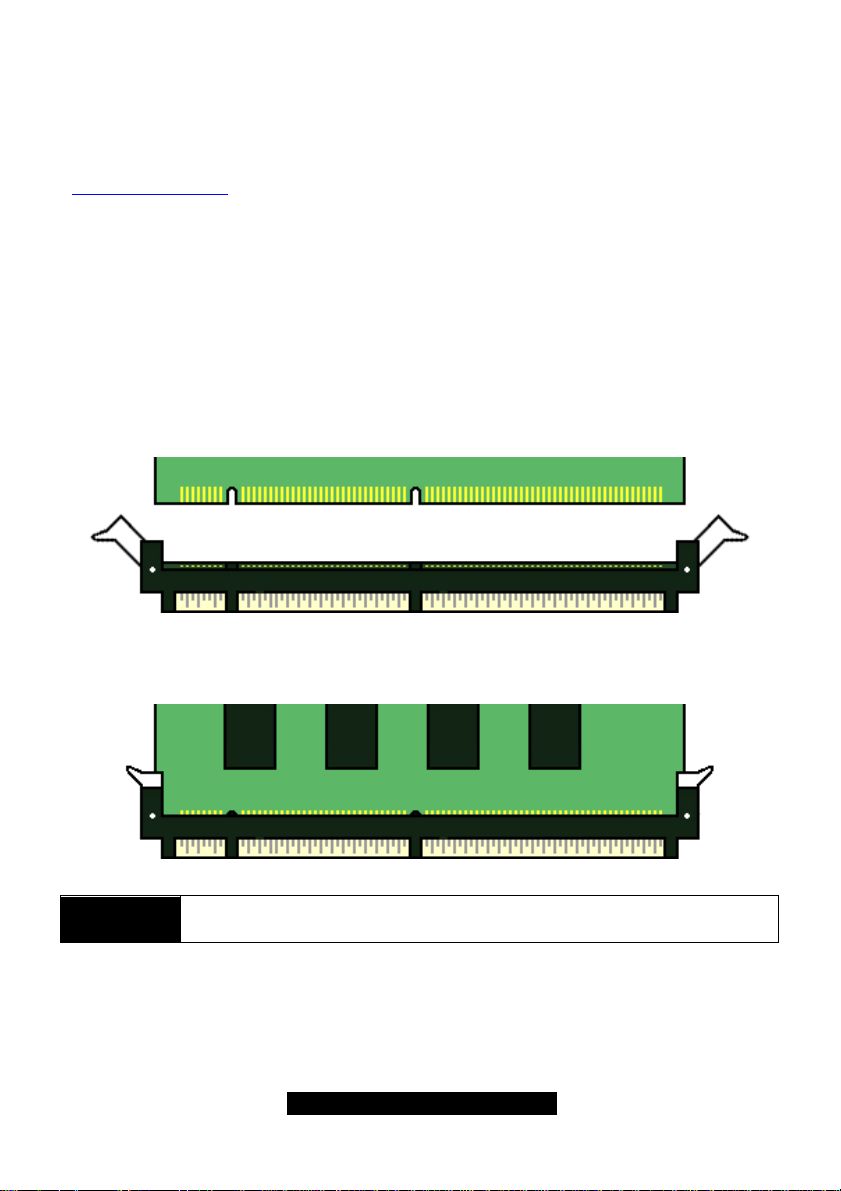
Step1: Line your module up so that the pins fit into the socket. There is only one way your DIMM
can fit properly. Make sure that the short row of pins is lined up with the short gap in the DIMM
socket, just as the long row of pins should line up with the long gap in the DIMM socket.
Step2: Insert the DIMM by pushing the module into the socket with even force Do not insert one
end and then the other: install the whole module at once or you might bend the DIMM pins. Make
sure the DIMM is securely seated.
NOTE
Look the DIMM into place by pushing the clips back on either end of the socket onto the notches
in the ends of the DIMM (see pictures above details).
Memory modules MUST be installed in pairs. Bank 0 to Bank
0, Bank 1 with Bank 1, etc.
12
http://www.TYAN.com
Page 13
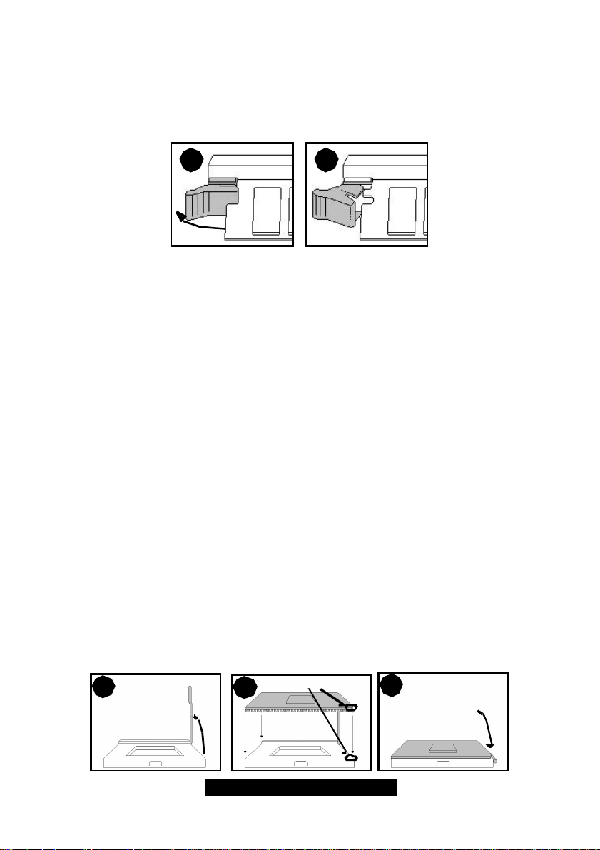
Removing a DIMM
Removing a DIMM is just the reverse: pull back the clips from the DIMM (see pictures on previous
page), and carefully pull the module straight out. Place the DIMMs in an anti-static bag as soon as
you remove them to avoid static damage.
1 2
Suggested Memory Configurations
The table below shows some of the possible memory configurations. Not all possible
configurations are listed. Your memory configurations may differ from one or more of the
combinations** shown below.
2.16 Installing the CPU and Cooling Fan
Intel Pentium III processors up to 1.2GHz can be used on this board. For more information on
CPU compatibility, check TYAN’s website at http://www.TYAN.com/
When installing your CPU, remember the following:
- Memory must be installed in pairs -
- The CPU is a sensitive electronic component and can easily be damaged by static
electricity
- Do not touch the CPU pins with your fingers
- You should be able to insert the CPU into the socket with virtually no force
- Do not press down hard on the CPU as you might bend or break pins, or otherwise
damage the CPU.
- The CPU voltage will automatically be detected by the motherboard, so there is not
need to set any jumpers or BIOS setting.
Installing the CPU
Before installing the CPU, check it for any visible damage. Make sure none of the pins are bent or
missing. Be sure where Pin 1 is on both the CPU and the socket. The following steps each have
corresponding picture next to it to help guide you through the installation.
Careful lift the arm of the ZIF socket until it is at 90 degree angle pointing away from the
motherboard. Be very careful not to damage any components that might be next the socket.
1
2
Pin 1
Arm moves down
3
to lock CPU
13
http://www.TYAN.com
Page 14
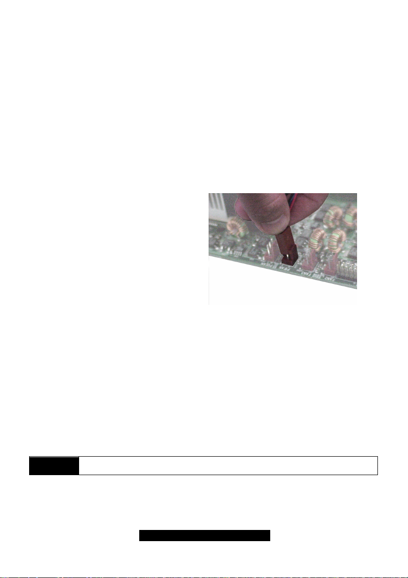
There are two beveled corners on the CPU, which will match the two angled corners on the
socket. Careful install the CPU by lining both Pin 1 on the CPU and Pin 1 on the socket, making
sure the pins actually fit into the socket. Do not force the CPU into the socket: check the pin
alignment of the CPU pins to socket holes.
Push down lightly on the CPU while lowering the arm on the socket to secure the CPU (see right).
A squeaking noise may be heard while lowering the arm or the socket may make a ‘click’ noise
when the arm is locked into position: these noises are normal.
Installing the Cooling Fans
After a CPU has been installed, you will need to install the proper cooling device for the CPU. This
device, a heatsink/fan combination can be purchased at many computer retail stores. Installation
of the cooling device may vary depending on the fan manufacturer’s design. You should also take
space into consideration when installing a cooling device: make sure the cooling device is not too
big, or else you may end up damaging components around the CPU socket.
TYAN highly recommends that you use a thin
layer of some type of thermal compound
(available from many computer retail stores),
between the CPU and the heatsink, to
maximize distribution of heat away from the
CPU. Please use extra caution when installing
any type of clamp-style fan, or else damage
may occur to the CPU socket and or the CPU
itself.
FAN
1
2
3
Ground
+12V
Speed
NOTE
Alternatively, if you wish to also install chassis fans for increased cooling, headers are provided to
power those fans as well. Chassis fan installation will vary depending on your chassis
manufacturer’s design. Please check with your chassis manufacturer for details on proper chassis
fan installation.
The FAN connector has a 12V, 0.3A limitation. TYAN takes no responsibility and
will not be held liable for damage related to the misuse of any FAN jumper.
Specifications
Voltage
12V
Amperage
0.3A
14
http://www.TYAN.com
Page 15
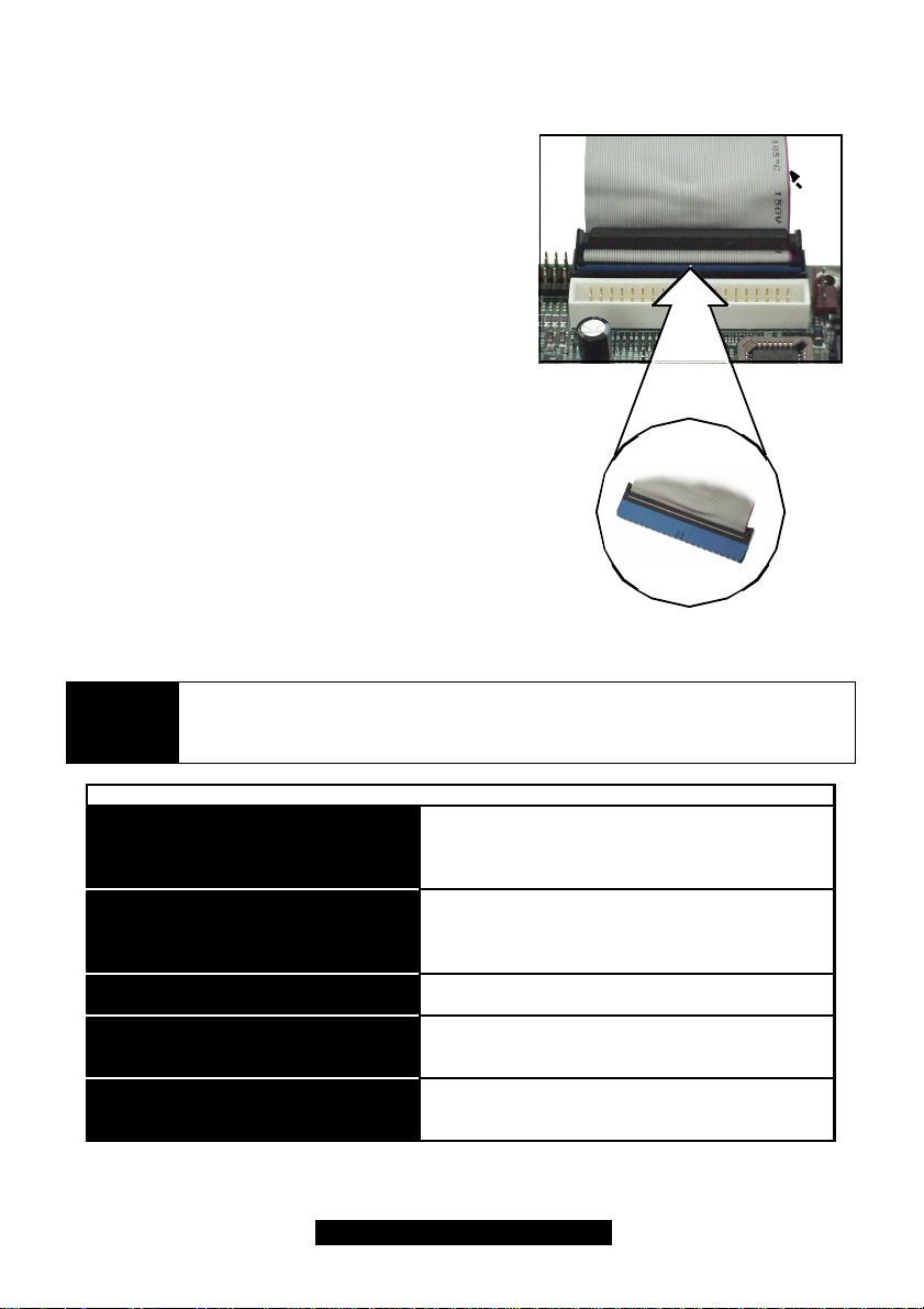
2.17 Connecting IDE and Floppy Drives
BLUE end goes to IDE connector
A variety of IDE and ATAPI-compliant devices can be
installed on this motherboard, such as hard disk drives
(HDDs) and CD-ROMs.
Please keep in mind that on this motherboard, the
primary IDE connector is BLACK, and the secondary
IDE connector is WHITE. See the picture to the rightfor
an example of the IDE cable properly connected to the
motherboard, with the BLUE end of the IDE cable
installed on the motherboard.
Pin 1 on the IDE cable is usually denoted by a red or
colored stripe down one side of the cable. That side of
the cable must match Pin 1 on the motherboard’s IDE
connector. There will also be a key pin on the cable that
matches with a notch in the IDE connector, to ensure
proper installation. Consult the documentation that
came with your IDE/ATAPI device, or contact the
device’s manufacturer for more details on installation.
Please note that UltraDMA-100/66 IDE HDDs require a
special 80-wire cable (see picture at right), which has
additional grounding wires. This cable has been
included with this motherboard for your convenience.
The UltraDMA-100/66 cable is backwards compatible
with UltraDMA-33 and legacy IDE HDDs.
Only TYAN-approved cables are recommended for this motherboard. If you are
NOTE
using an existing configuration with older cables, your system might not function
properly. Use only TYAN-approved cables (i.e. the ones included with your new
motherboard).
Pin 1
Some symptoms of incorrectly installed HDDs are...
HDDs are not auto-detected
Hard Disk Drive Fail message at bootup
No video or beeps during bootup
HDD lights are constantly on
HDD does not power on
May be a Master/Slave configuration problem, bad
IDE cable, or BIOS mis-configuration. Consult the
HDD documentation or contact your HDD vendor.
May be a bad cable or lack of power going to the
drive. Check the cables for damage and bad connections.
Usually means the cable was installed backwards.
Bad IDE cable or defective drives/motherboard. Try
another HDD, or contact your HDD vendor.
Check power cables and cabling. May be a bad
power supply or IDE drive problem.
15
http://www.TYAN.com
Page 16
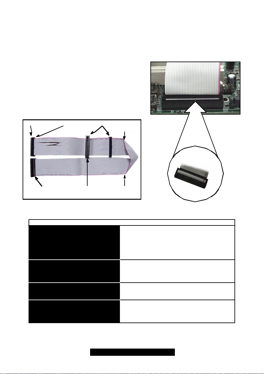
Connecting Floppy Drives
Figure 2.
4*
Match striped side with Pin 1
See the picture below for an example of a floppy cable. Most of the current floppy drives on the
market require that the cable be installed with the colored stripe positioned next to the power
connector. In most cases, there will be a key pin on the cable which will force a proper connection
of the cable.
The first floppy drive (sometimes denoted as A:) is
usually attached to the end of the cable with the twist
in it. Drive B: is usually connected to the second or
third connector in the cable (the second or third
connector after you install Drive A:). Refer to your
floppy drive’s installation instructions (if available), or
Pin 1
contact your dealer if you are unsure about how to
attach the floppy drive(s). Remember, you can only
have 2 floppy drives connected at any given time.
3.5” connector
This connector goes
to motherboard
FDDs are not auto-detected
Floppy Drive Fail message at bootup
FDD does not power on
5.25” connector Colored stripe
Some symptoms of incorrectly installed FDDs are...
Drive B:Drive A:
Colored stripe
indicates Pin 1
indicates Pin 1
Usually caused by faulty cables, cables put in backwards, or a bad floppy or motherboard. Try another
floppy drive to verify the problem or try another
cable. Also check to see if the onboard floppy is
enabled in the BIOS.
The cable, floppy, or motherboard may be faulty. Try
another cable or floppy drive to verify.
Check power cables and cabling. May be a bad
power supply or IDE drive problem.
FDD light is constantly on
Usually signifies that the cable is on backwards.
Reverse the cable at the floppy drive end and try
again.
16
http://www.TYAN.com
Page 17
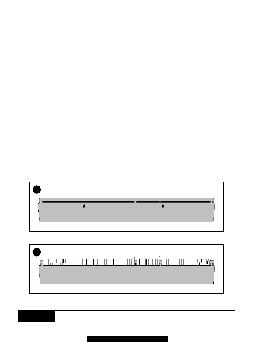
2.18 Installing Add-in Cards
Figure 2.1b
*
There are a few rules you need to follow when installing add-on cards. In order to assure proper
operation and a quick installation, adhere to the following guidelines:
- If you are going to install a PCI-bus interface card on your system, be aware that any one of the
five PCI slots can support a Master or Slave device.
- NEVER force a card into a slot. If it won’t fit properly, look at the socket on the motherboard to
make sure there are no wires or other obstructions to the slot. Damage may occur otherwise.
- NEVER plug an ISA card into a PCI slot. You will void your warranty, and you will damage your
system board if you try to do this.
- When plugging the card in, especially when installing long cards, try to push the entire card in at
one time. Don’t force one end of the card into the socket first and then the other, or a rocking
motion between the card and the slot might occur, and could damage the pins within the socket.
- Make sure the cards are seated securely into their slots.
- Before turning on the system, make sure no cards are touching.
- Check the PCI device specifications with the PCI slot specifications BEFORE installing!
When installing the add-on cards, make sure the cards are installed with even force; do not insert
one end and then the other. See the before (Figure 2.1a) and after (Figure 2.1b) example
installation images below for details.
1
2
NOTE
Check orientation of card when installing
Figure 2.1a *
Push card down with even force
*Your PCI slots may not look like those in the above diagrams; they are used
simply as examples.
17
http://www.TYAN.com
Page 18
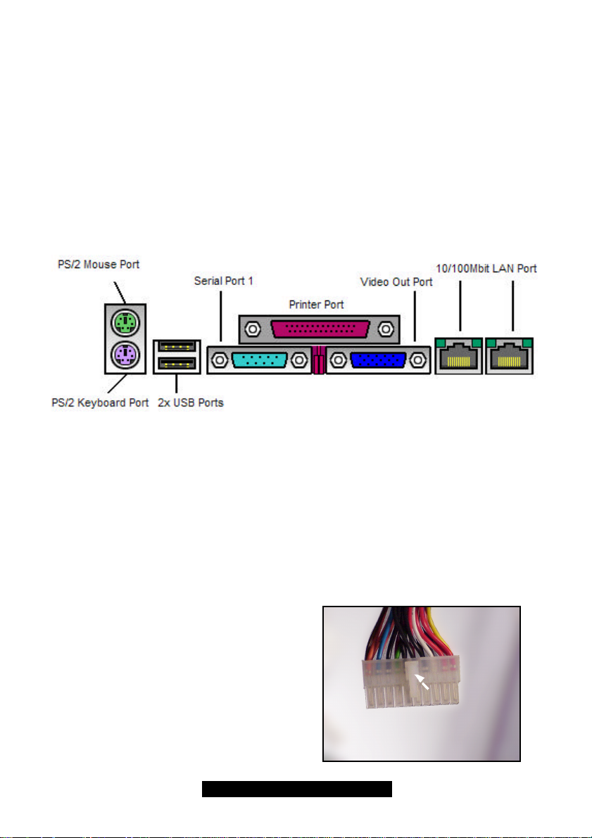
2.19 Connecting PS/2, USB, and Serial Devices
This motherboard includes ports for PS/2 mouse and keyboard, Universal Serial Bus (USB)
devices, and serial and parallel devices. Please note that the upper PS/2 port is the mouse port,
and the lower PS/2 port is for the keyboard (see Figure 2.3 below).
Installation of peripheral/external devices may vary. For details on installation of devices into the
various ports shown below, please consult your device’s documentation, device manufacturer, or
your dealer for details.
Connecting Serial and Parallel Ports
The serial and parallel ports can be used to connect various devices such as a mouse or printer.
The connectors can only be connected one way: be sure and check the orientation of the
connector before installing it into the port.
2.20Connecting the power supply*
This motherboard requires the following:
• ATX power supply, one that conforms to ATX standard 2.01 or better
The clip on the power connector should lock over the tab on the onboard connector. You shouldn’t
be able to plug the power connector in any other way but just to be safe, make sure it looks like
Figure 2.4b. Make certain that you do not miss connecting any of the pins because if you do, you
will void your warranty and possibly cause damage to yourself and/or your motherboard when the
power is turned on. After connecting the power, make sure the connector is seated firmly into its
socket so it will not become loose or fall off when the computer is jostled or moved.
Step 1: Shown on the right, in Figure 2.4a, is
the 20-pin connector of the ATX power supply.
Note the clip in the image: it will help you install
the plug correctly.
This is the CLIP
18
http://www.TYAN.com
Page 19
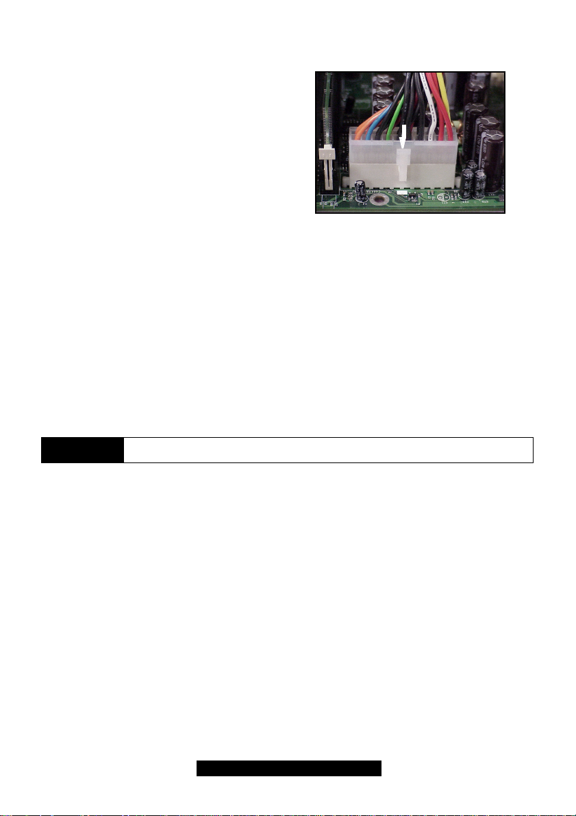
Step 2: Shown on the right, in Figure 2.4b, is
the 20-pin connector plugged into the board*.
The clip is over the TAB of the onboard
connector.
When you connect the cable into the
motherboard’s 20-pin onboard connector, it will
make a CLICK noise as it is installed.
This is normal.
2.21 You are done!
Other than checking the jumper settings and cable connections, and putting the case back
together, you are done.
Installing a new motherboard may seem difficult, but by following these directions, you should
have a fairly uneventful time installing our products. If you do encounter problems, your
vendor/dealer will be able to help you, or you can consult one of our many technical support
solutions (i.e. website or phone).
Note the TAB
NOTE
Your ATX power connector may not look like those in the above diagram; they
are used simply as examples.
19
http://www.TYAN.com
Page 20
Chapter 3: BIOS Setup
Introduction to the BIOS setup
The BIOS is the basic input/output system, required by the computer to perform functions such as
CPU and hard drive support. This chapter describes different settings for the BIOS that can be
used to configure your system.
The BIOS section of the manual is subject to change without notice and is provided here for
reference purposes only. The settings and configurations of the BIOS are current at the time of
print, and therefore they may not be exactly the same as that displayed on your screen.
This manual describes the BIOS setup program. The setup program lets you modify basic
configuration settings. The settings are then stored in a dedicated battery-backed memory, called
NVRAM, that retains the information when the power is turned off.
The BIOS in your motherboard is a customized version of industry-standard BIOS for IBM PC ATcompatible personal computers. It supports Intel x86 and compatible processors. The BIOS
provides critical low-level support for the system central processing, memory, and I/O subsystems.
The BIOS has been customized by adding important, but non-standard, features such as virus
and password protection, power management, and detailed fine-tuning of the chipset controlling
the system. The rest of this manual is intended to guide you through the process of configuring
your system using this BIOS setup program.
Starting Setup
The BIOS is immediately activated when you first turn on the computer. The BIOS reads system
configuration information in CMOS RAM and begins the process of checking out the system and
configuring it through the Power-On Self Test (POST).
When these preliminaries are finished, the BIOS will seek an operating system on one of the data
storage devices (HDD, floppy drive, etc.) If one is found, the BIOS will launch that operating
system and hand control of system operations to it. You can start the setup program by pressing
the [DEL] key while the system is booting up.
Setup Keys
The table below shows how to navigate in the setup program using the keyboard.
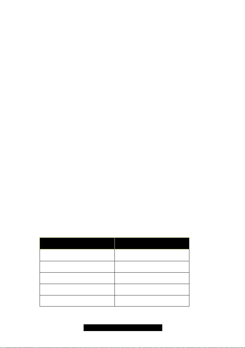
Key Function
Tab
Left/Right Arrow Keys
Up/Down Arrow Keys Move between selections
Enter Opens highlighted selection
PgUp/PgDn Keys Change highlighted selection
Getting Help
Moves from one selection to the
next
Change from one menu to the
next
20
http://www.TYAN.com
Page 21
Press F1 to display a small help window that describes the appropriate keys to use and the
possible selections for the highlighted item. To exit the Help Window, press ESC or the F1 key
again.
In Case of Problems
If you discover that you have trouble starting the computer after making and saving changes with
the BIOS setup program, you can restart the computer by either:
Ø Holding the Power button down until the machine turns off.
The best advice is to alter only settings that you thoroughly understand. In particular, do not
change settings in the Chipset section unless you’re absolutely sure you need to. The Chipset
defaults were carefully chosen by TYAN and or your system manufacturer for the best
performance and reliability. Even a seemingly small change to anyone of the Chipset options
without consideration, can cause your system to become unstable immediately or progressively.
Setup Variations
Not all systems have the same setup program. While the basic look and function of the setup
program remains more or less the same for all systems, the appearance of your Setup options
may or may not follow the same order listed in this manual. In addition, the final layout of all Setup
options depends on your system designer. They can decide that certain items that are listed in the
following pages remain hidden from user alteration.
3.1 Main Setup
In this section, you can alter general features such as the data and time, as well as access to the
IDE configuration options. Note that the options listed below are for options that can directly be
changed within the Main Setup screen.
System Time
System Date
3.2 Advanced
Options related to System settings can be altered through the following.
Super IO Configuration
IDE Configuration
Floppy Configuration
Boot Settings Configuration
Onboard Device Configuration
Event Log Configuration
System Health Monitor
Remote Access Configuration
HH: Hours (24 hour format)
MM: Minutes
SS: Seconds
MM: Month
DD: Day
YYYY: Year
All settings discussed in following sections.
Adjusts the system clock.
Adjusts the system date.
21
http://www.TYAN.com
Page 22
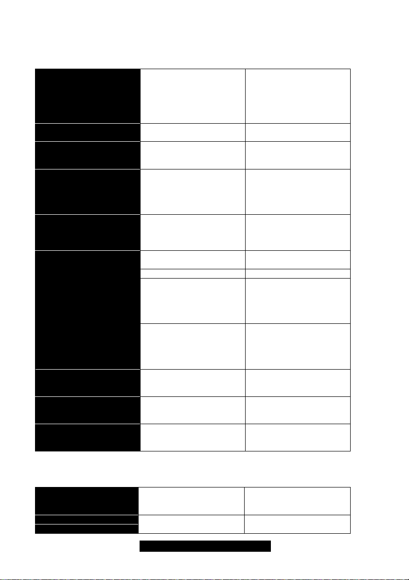
3.2-A Super IO Configuration
Options related to the IO interface can be altered through the following.
Serial Port 1, 2
Serial 2 Mode
Serial Base I/O
Serial Interrupt
Parallel Port
Parallel Port Mode
Parallel Address
Parallel IRQ
ECP DMA Channel
Enabled (d)
Disabled
Auto
Enabled (d)
Disabled
3F8, 2F8 (d)
3E8, 2E8
IRQ3 (d)
IRQ4
Enabled
Disabled
Auto (d)
Output Only (d) Standard one-way protocol
Bi-directional Two-way protocol
EPP Enhanced Parallel Port
ECP Enhanced Compatibility
378 (d)
278
3BC
IRQ5 (d)
IRQ7
DMA1 (d)
DMA2
Toggles use of serial ports
A and or B. Enabling ports
also requires you to enter
the I/O address for that
port unless you select
Auto.
Toggles the onboard Serial
B port.
These options are
dependent on the IRQ and
vice versa.
These IRQs are paired
with the Base I/O option.
Recommended config:
2F8 & IRQ3
3F8 & IRQ4
Enabled requires manual
input of port parameters.
We recommend you leave
this option on Auto.
for parallel devices.
may provide higher
bandwidth if an EPP
compliant device is used
(e.g. parallel Zip drive).
Port may provide higher
bandwidth if an ECP
compliant device is used
(e.g. parallel Zip drive).
These options appear
when the parallel port is
set to Enabled.
These options appear
when the parallel port is
set to Enabled.
These options appear
when parallel port is set to
Enabled.
3.2-B IDE Configuration
Options related to the IDE controller can be altered through the following.
Onboard PCI IDE
Controller
Primary Master/Slave
Secondary Master/Slave
Both (d)
Primary
Secondary
Auto (d)
Disabled
Leave as Default.
Leave as Default.
22
http://www.TYAN.com
Page 23
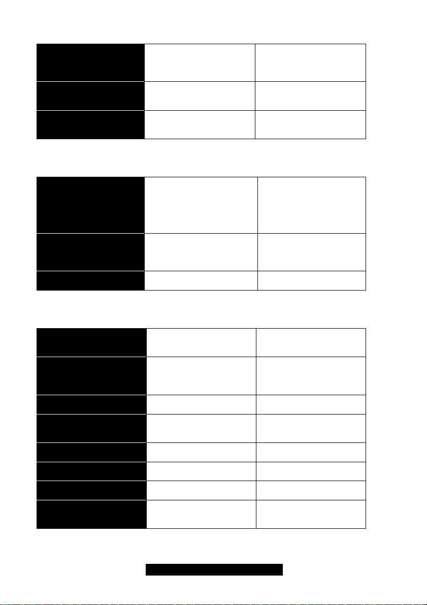
Enabled
Hard Disk Write Protect
ATAPI Detect Time Out
ATAPI 80pin Cable Detect
3.2-C Floppy Configuration
Options related to floppy drives can be altered through the following.
Disabled (d)
0, 5, 10, 15, 2.0x, 2.5x,
3.0x, 3.5x (d)
Host & Device (d)
Host
Device
Toggles the use of boot
sector protection. This
ensures that no viruses can
damage the hard drive.
Defines how long the
system will try to detect
ATAPI devices for.
Toggles the detection of
80wire IDE cables.
360KB, 5 ¼”
Floppy A
Floppy B
Diskette Write Protect
Floppy Drive Seek
3.2-D Boot Settings Configuration
Options related to startup settings can be altered through the following.
Quick Boot
Quiet Boot
Add-On Rom Display
Mode
Boot up Num-Lock
Boot up CPU Speed
PS/2 Mouse Support
Typematic Rate
System Keyboard
1.2MB, 5 ¼”
720KB, 3 ½”
1.44MB, 3 ½” (d)
2.88MB, 3 ½”
Disabled
Enabled
Disabled (d)
Enabled
Disabled (d)
Enabled
Disabled (d)
Enabled (d)
Disabled
Force BIOS (d)
Keep Current
On (d)
Off
High (d)
Low
Enabled (d)
Disabled
Fast (d)
Slow
Present (d)
Unavailable
Defines the floppy drive
type.
Toggles write protection.
This will be effective only if
device is access through
BIOS.
Toggles floppy drive
seeking during POST.
When set to Enabled,
some self tests will be
skipped during POST.
If set to Enabled, OEM
logo will be displayed
instead of POST
messages.
Leave as Default.
Specifies whether NumLock will be on or off
during bootup.
Specifies the CPU speed
during startup.
Toggles the use of the
PS/2 mouse port.
Changes speed of key
repeat rate.
Will allow continual boot if
the keyboard is not
attached.
23
http://www.TYAN.com
Page 24
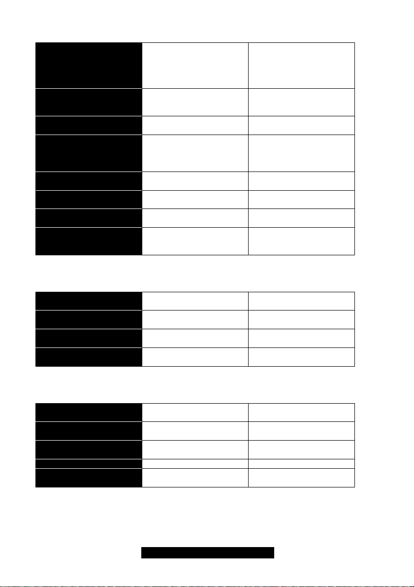
Absent
Primary Display
Parity Check
Boot to OS/2
Wait for F1 if “error”
Hit “Del” Message
Internal Cache
Processor Serial Number
System BIOS Cacheable
3.2-E Onboard Device Configuration
Options related to onboard devices can be altered through the following.
VGA/EGA (d)
Color 40x25
Color 80x25
Monochrome)
Enabled
Disabled (d)
Yes
No (d)
Enabled (d)
Disabled
Enabled (d)
Disabled
Write Back (d)
Page Flip
Enabled
Disabled (d)
Enabled (d)
Disabled
Changes default video
mode. Leave as is.
Toggles checking of
system memory for
corruption.
Toggles boot to OS/2 OS.
Leave as default.
If Enabled, you will have to
press F1 for the system to
continue booting if an error
is detected during POST.
Toggles display of pressing
DEL key to enter BIOS.
Leave as default.
Toggles the use of
Pentium III serial number.
Toggles the use of caching
BIOS instructions into RAM
for faster processing.
Onboard ATI Video
Onboard SCSI
Onboard 82559 (1)
Onboard 82559 (2)
3.2-F Event Log Configuration
Options related to Event Logging can be altered through the following.
Event Logging
ECC Event Logging
Clear All Event Logs
View Event Log Views events.
Mark All Events As Read
Enabled (d)
Disabled
Enabled (d)
Disabled
Enabled (d)
Disabled
Enabled (d)
Disabled
Enabled
Disabled (d)
Enabled
Disabled (d)
Yes
No
OK
Cancel
Toggles the onboard ATI
video graphics.
Toggles the onboard SCSI
controller.
Toggles LAN port 1.
Toggles LAN port 2.
Toggles event logging.
Records errors.
Toggles ECC event
logging. Records errors.
Clears all event logs.
If OK, BIOS will clear event
log.
24
http://www.TYAN.com
 Loading...