


Thunder K8SRE
///
Version 1.0
S2891
Copyright
Copyright © TYAN Computer Corporation, 2004-2005. All rights reserved. No
part of this manual may be reproduced or translated without prior written
consent from TYAN Computer Corp.
Trademark
All registered and unregistered trademarks and company names containe d in
this manual are property of their respective owners including, but not limited to
the following.
TYAN, Taro and Thunder K8SRE are trademarks of TYAN Computer
Corporation.
AMD, Opteron, and combinations thereof are trademarks of AMD Corporation.
Nvidia and nForce are trademarks of Nvidia Corporation
Microsoft, Windows are trademarks of Microsoft Corporation.
SuSE,is a trademark of SuSE AG.
Linux is a trademark of Linus Torvalds
IBM, PC, AT, and PS/2 are trademarks of IBM Corporation.
Winbond is a trademark of Winbond Electronics Corporation.
Notice
Information contained in this document is furnished by TYAN Computer
Corporation and has been reviewed for accuracy and reliability prior to printing.
TYAN assumes no liability whatsoever, and disclaims any express or implied
warranty, relating to sale and/or use of TYAN products including liability or
warranties relating to fitness for a particular purpose or merchantability. TYAN
retains the right to make changes to product descriptions and/or specifications
at any time, without notice. In no event will TYAN be held liable for any direct or
indirect, incidental or consequential damage, loss of use, loss of data or other
malady resulting from errors or inaccuracies of information contained in this
document.
http://www.tyan.com
1

Table of Contents
Chapter 1: Introduction
1.1 Congratulations Page 3
1.2 Hardware Specifications Page 3
1.3 Software Specifications Page 5
Chapter 2: Board Installation
2.1 Board Image Page 8
2.2 Block Diagram Page 9
2.3 Board Parts, Jumpers and Connectors Page 10
2.4 Installing the Processor(s) Page 18
2.5 Heatsink Retention Frame Installation Page 19
2.6 Thermal Interface Material Page 20
2.7 Heatsink Installation Procedures Page 21
2.8 Finishing Installing Heatsink Page 23
2.9 Tips on Installing Motherboard in Chassis Page 24
2.10 Installing the Memory Page 25
2.11 Attaching Drive Cables Page 28
2.12 Installing Add-In Cards Page 30
2.13 Connecting External Devices Page 31
2.14 Installing the Power Supply Page 32
2.15 Finishing Up Page 33
Chapter 3: BIOS
3.1 BIOS Setup Utility Page 35
3.2 BIOS Menu Bar Page 36
3.3 BIOS Legend Bar Page 36
3.4 Getting Help Page 36
3.5 BIOS Main Menu Page 37
3.6 BIOS Advanced Menu Page 38
3.7
BIOS Memory Menu
3.8
Security Menu
3.9 BIOS Boot Menu Page 54
3.10
Power Menu
3.11
BIOS Exit Menu
Chapter 4: Diagnostics
4.1 Beep Codes Page 59
4.2 Flash Utility Page 59
4.3 BIOS Post Code Page 60
Glossary
Technical Support
Page 52
Page 53
Page 56
Page 57
Page 59
Page 63
Page 69
http://www.tyan.com
2

Chapter 1: Introduction
1.1 - Congratulations
You have purchased one of the most powerful server solutions. The Thunder
K8SRE (S2891) is a high-end server mainboard, based on Nvidia nForceTM
Professional 2200 Media and Communications Processor (MCP) and AMD
8131 PCI-X HyperTransport™ Tunnel.
Designed to support up to two AMD Opteron™ (200 series) processors and
16GB of DDR400 memory, the S2891 is ideal for CPU, memory, and network
intensive applications required in the HPC and clustering applications.
1.2 - Hardware Specifications
Processors
•Two uPGA 940-pin ZIF sockets
•Two onboard 4-phase VRM
•Supports one or two AMD
Opteron
•Scalable 32bit and 64bit
computing
•Integrated 144-bit DDR memory
controller (128bit+16bit ECC)
Chipset
•Nvidia nForce Professional 2200
(CrushK8-04 Pro)
•AMD 8131™ PCI-X Tunnel
•Winbond W83627HF Super I/O
•Analog Devices ADT7463
Hardware Monitoring IC
Memory
•128-bit dual channel memory bus
•Total Eight DDR DIMM sockets
(Four per CPU)
•Supports up to 16GB Registered
DDR
•Supports ECC and Chipkill
•Supports DDR400
TM
processors
http://www.tyan.com
Integrated Video Controller
•ATI® RAGE XL PCI VGA w/8MB
onboard memory
Integrated LAN Controllers
•One Broadcom
Port GbE
- Connected to PCI-X bus A
(133MHz)
- Two RJ-45 LAN connectors with
LEDs
- Two front panel LED headers
Integrated Enhanced IDE
Controller
•Two IDE dual-drive ports for up to
four EIDE devices
•Supports for ATA-133 IDE drives
and ATAPI devices
System Management
• Total ten 3-pin fan headers with
PWM support
- Seven fan headers with
tachometer
•One 2-pin chassis intrusion hdr
•Temperature, voltage and fan
monitoring
•Port 80h LED 7-segment display
3
®
BCM5704 Dual

Expansion Slots
•One PCI Express x16 slot with
riser support for the following
configuration
- One 16 slot
- Future multiple slot riser support
in development (Check
TYAN.COM for updates)
•One Tyan TARO
TM
SODIMM
100MHz (PCI-X B)
•One PCI-X 100MHz slot (PCI-X B)
•Total of three usable slots in
pedestal chassis or two slots in
1U rackmount configuration
Integrated SATAII Controllers
•Two integrated dual port SATAII
controllers
•Four SATA connectors support up
to four drives
•Supports 3.0Gb/s per port
•NvRAID
TM
v2.0 support
•Supports RAID 0, 1, and 0+1
Integrated I/O
•One floppy connector supports up
to two drives
•One parallel port header and two
serial ports (one connector, one
header)
•Six USB2.0 ports (two rear
connectors & four front panel
headers)
•One 15-pin VGA connector
•PS/2 mouse and keyboard
connectors
Regulatory
•FCC Class B (DoC)
•European Community CE (DoC)
Intelligent Platform
Management Interface Header
•Tyan Server Management
Daughter card (optional)
supports features listed below
via SMDC header
- Baseboard Management
Controller (BMC)
- Tailored for IPMI
- Supports KCS and BT styles
- Flexible Windows or Linux
management solution
- Supports RMCP and SNMP
protocols
- Supports ASF standard and EMP
2
- 1
C serial multi-master controllers
and UARTs
- Built-in IPMB connector
- Remote power on/off and reset
support (IPMI-over-LAN)
BIOS
•Phoenix BIOS on 8Mbit LPC
Flash ROM
•ACPI 2.0 and SRAT support
•PXE via Ethernet
•USB device boot
•SMBIOS 2.3.1, BBS 1.1 compliant
•48-bit LBA support
Form Factor
•Extended ATX Footprint (12”x13”,
304.8x330.2mm)
•SSI 3.0/3.51 (24 + 8 pin) power
connectors
•Serial (one) and VGA (one)
connectors
•Stacked USB 2.0 (two)
connectors
•Stacked PS/2 connectors
•Two RJ-45 LAN connectors with
LEDs
http://www.tyan.com
4

1.3 - Software Specifications
OS (Operating System) Support
Microsoft Windows 2000
Microsoft Windows XP
Microsoft Windows Server 2003
SUSE Professional 9.x and SLES 9
RHEL3 Update 4
TYAN reserves the right to add support or discontinue support for any OS with
or without notice.
Remember to visit TYAN’s websit at http://www.tyan.com. There you can find
information on all of TYAN’s products with FAQs, manuals, and BIOS updates.
http://www.tyan.com
5

NOTES:
http://www.tyan.com
6
Chapter 2: Board Installation
Precautions: The Thunder K8SRE supports SSI, EPS12V type power supplies
(24pin + 8pin) and will not operate with any other types. For proper power
supply installation procedures see page 32.
DO NOT USE ATX 2.x or ATXGES power supplies as they will damage the
board and void your warranty.
How to install our products right… the first time
The first thing you should do is reading this user’s manual. It contains important
information that will make configuration and setup much easier. Here are some
precautions you should take when installing your motherboard:
(1) Ground yourself properly before removing your motherboard from the
antistatic bag. Unplug the power from your computer power supply and
then touch a safely grounded object to release static charge (i.e. po wer
supply case). For the safest conditions, TYAN recommends wearing a
static safety wrist strap.
(2) Hold the moth erboard by its edges and do not touch the bottom of the
board, or flex the board in any way.
(3) Avoid touching the motherboard components, IC chips, connectors,
memory modules, and leads.
(4) Place the motherboard on a grounded antistatic surface or on the
antistatic bag that the board was shipped in.
(5) Inspect the board for damage.
The following pages include details on how to install your motherboard into your
chassis, as well as installing the processor, memory, disk drives and cables.
NOTE
DO NOT APPLY POWER TO THE BOARD IF IT HAS BEEN
DAMAGED
http://www.tyan.com
7
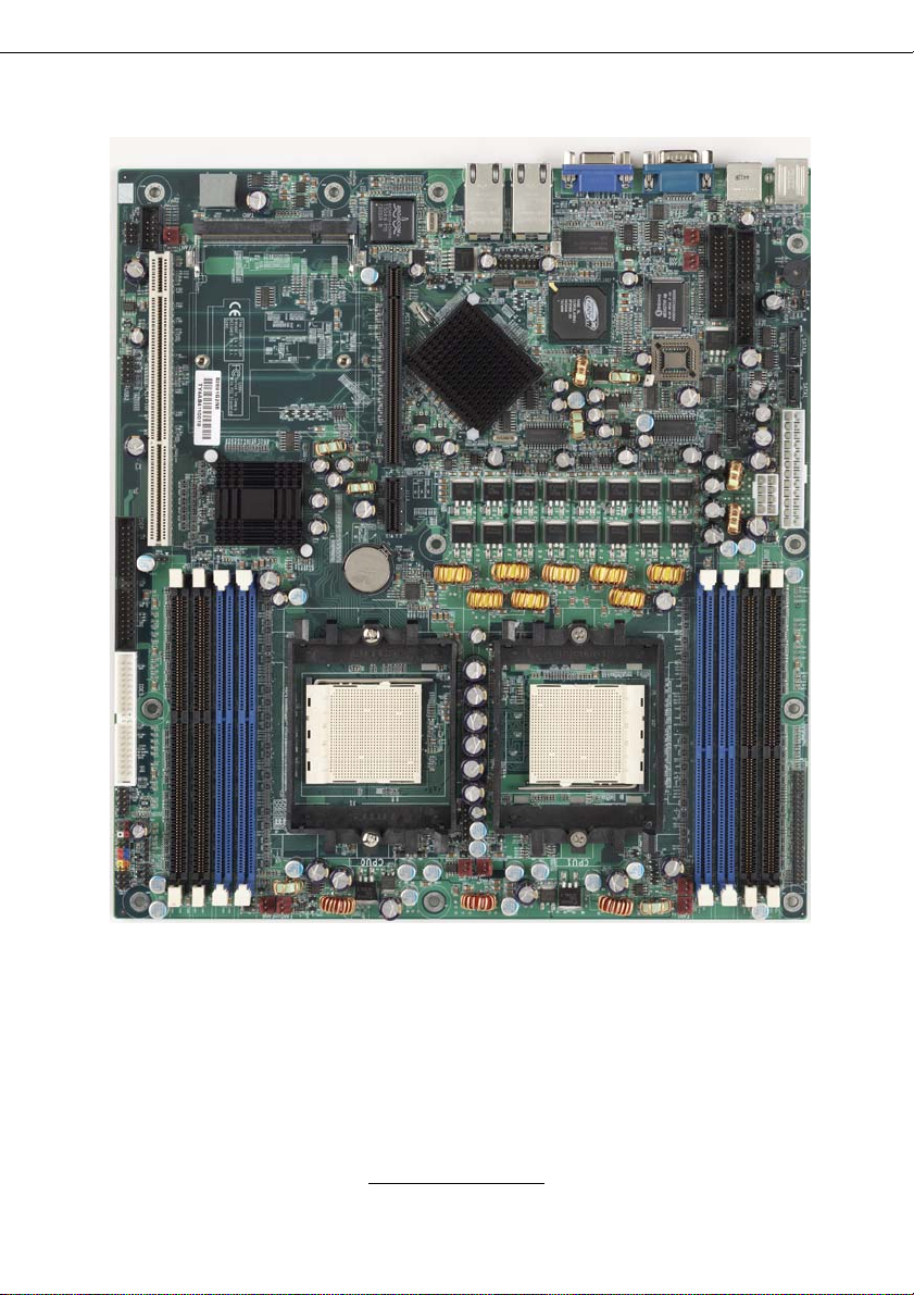
2.1- Board Image
This picture is representative of the latest board revision a vailable at
the time of publishing. The board you receive may or may not look
exactly like the above picture.
The following page includes details on the vital components of this
motherboard.
http://www.tyan.com
8
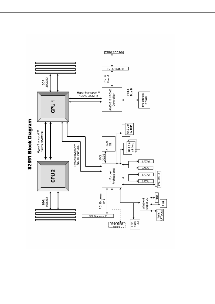
2.2 - Block Diagram
Thunder K8SRE (S2891) Block Diagram
http://www.tyan.com
9
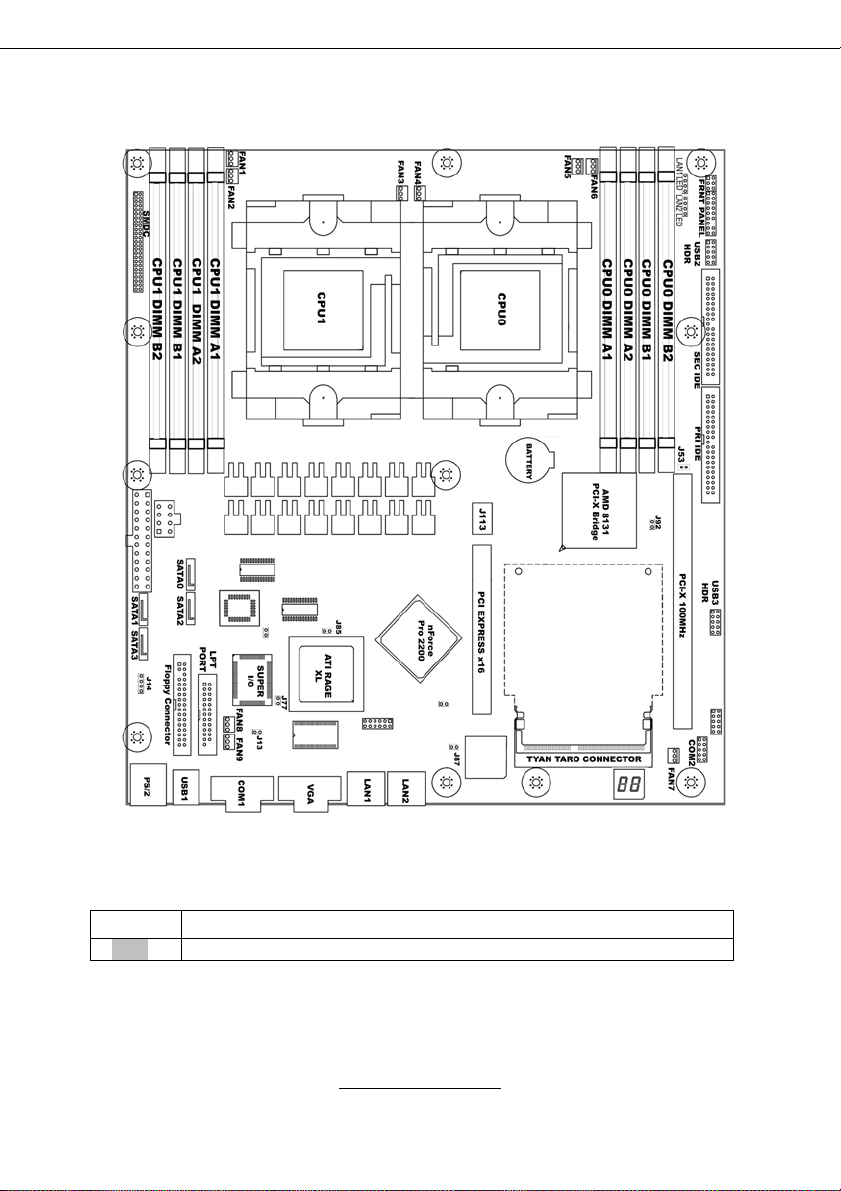
2.3 - Board Parts, Jumpers and Connectors
This diagram is representative of the latest board revision available at the time of
publishing. The board you receive may not look exactly like the above diagram.
Jumper Legend
OPEN - Jumper OFF, without jumper cover
CLOSED – Jumper ON, with jumper cover
10
http://www.tyan.com
Jumper/Connector Function
J14 Onboard Buzzer/Speaker Header
J25/J140 USB Front Panel Header
J42 COM2 Header
J53 PCI-X Slot & TARO Connector Bus Speed Override
J73/J75 Front Panel LAN LED Headers
J77 INTR-Chassis Intrusion Header
J85 ATI Video Disable Jumper
J87 Gigabit Ethernet Disable Jumper
J112 Clear CMOS Jumper
J113 PCI Express x16 slot with riser card support
J139 Front Panel Header
TARO Connector
Connector for TYAN TAROTMSO-DIMM Controller
Cards
http://www.tyan.com
11

J53
J25
J140
J14
J77
J42
http://www.tyan.com
12

J14: Onboard Buzzer/Speaker Header
Closed Pin-3 and 4 (Default) - Onboard Buzzer
enabled
Open Pin-3 and 4 – Disable onboard buzzer or
connect to chassis speaker.
J25 & J140: USB Front Panel Headers
Use these headers to connect to chassis front panel
USB connectors.
Signal Pin Pin Signal
VCC
Data Data +
GND
KEY
1 2
3 4
5 6
7 8
9 10
VCC
Data -
Data +
GND
GND
J42: COM2 Header
Use these pin definitions to connect a port to COM2.
Signal Pin Pin Signal
Data Carrier Detect
Receive-Data
Transfer-Data
Data Terminal Ready
Ground
1 2
3 4
5 6
7 8
9 10
Data-Set-Ready
Request-to-Send
Clear-to-Send
Ring-Indicator
J77: INTR-Chassis Intrusion Header
Pin1: Case Open
Pin2: GND
J53: PCI-X Slot & TARO Connector Bus Speed Override
Open-(Default) Allows PCI-X slot and the TARO slot to
operate at up to 100MHz (Maximum one PCI-X 100
device)
Closed-Forces PCI-X slot and the TARO slot to operate
at a maximum bus speed of 66MHz.
http://www.tyan.com
13
NC/KEY

J113
J73
J139
J75
J112
J85
TARO
J87
J85: ATI Video Disable
Open-(Default) Enable onboard video
Closed-Disable onboard video
J113
The PCI Express x16 slot supports 1U or 2U riser cards. See p. 4 for the
detailed configuration.
http://www.tyan.com
14

J87: Gigabit Ethernet Disable
Open-(Default) Enable onboard Gigabit Ethernet
Closed-Disable onboard Gigabit Ethernet
J112: Reset CMOS Jumper
You can reset CMOS settings by using this jumper if
(Clear)
(Default)
you have lost your system/setup password or need to
clear system BIOS setting.
Power off system and disconnect both power
connectors from the motherboard.
Use jumper cap to close J112 for several seconds to
Clear CMOS.
Remove jumper cap (default setting).
Reconnect power & power on system.
J139: Front Panel Header
HDDLED+
HDDLEDReset SW
Reset SW
+5V
NC
+5V Standby
SMBUS DATA
SMBUS CLOCK
1 2
3 4
5 6
7 8
9 10
11 12
13 14
15 16
17 18
PWR LED+
PWR LED-
PWR SW
PWR SW
SLEEP SW
SLEEP SW
NC (KEY)
GND
Chassis Intr# (Active
Low)
J73/J75: Front Panel LAN LED Headers
Pin1 Yellow+
Pin2 YellowPin3 Green+
Pin4 Green-
100Mb
LNK/ACT
10Mb
LNK/ACT
TARO SO-DIMM Connector
The TARO connector supports TYAN M7901, M7902 and M8110.
http://www.tyan.com
15
Gigabit
LNK/ACT

FAN1
FAN3
FAN2
FAN4
FAN6FAN5
FAN8
FAN9
http://www.tyan.com
16
FAN7

Fan Connectors and Hardware Monitoring
1 2 3
Pin1=Ground
Pin2= +12v
Pin3= Tachometer
Use these headers to connect the processor or chassis
cooling fan to your motherboard to keep the system
stable and reliable.
FAN1 Direct +12V from power supply
(No power control and tachometer monitor)
FAN2 Fan power control: ADT7463A pin10
Fan tachometer monitor: ADT7463A pin12
FAN3 Fan power control: W83627HF/AW pin116
Fan tachometer monitor: W83627HF/AW pin113
FAN4 Fan power control: W83627HF/AW pin115
Fan tachometer monitor: W83627HF/AW pin112
FAN5 Direct +12V from power supply
(No power control and tachometer monitor)
FAN6 Fan power control: ADT7463A pin11
Fan tachometer monitor: ADT7463A pin24
FAN7 Direct +12V from power supply
(No power control and tachometer monitor)
FAN8 Fan tachometer monitor: W83627HF/AW pin111
FAN9 Fan power control: ADT7463A pin13
Fan tachometer monitor: ADT7463A pin9
CPU Temperature Monitoring
CPU1: ADT7463A pin15 and 16 (with processor differential thermal output)
CPU2: ADT7463A pin17 and 18 (with processor differential thermal output)
CPU1 area: W83627HF/AW pin104 (with R1794 10K themistor)
CPU2 area: W83627HF/AW pin103 (with R1792 10K themistor)
CPU VRM area: W83627HF/AW pin102 (with R179310K themistor)
Voltage Monitoring
+12V ADT7463A pin21
+5V ADT7463A pin20
3.3V W83627HF pin98
+3.3V standby ADT7463A pin4
CPU1 Vcore 1.55 V W83627HF pin100
CPU2 Vcore 1.55 V W83627HF pin99
CPU1 DDR VTT 1.25V W83627HF pin96
CPU2 DDR VTT 1.25V ADT7463A pin23
CPU1 DDR 2.5V W83627HF pin95
CPU2 DDR 2.5V ADT7463A pin22
http://www.tyan.com
17

2.4 - Installing the Processor(s)
Your brand new Thunder K8SRE supports the latest 64-bit processor
technology from AMD. Only AMD Opteron™ processor 200 series are certified
and supported with this motherboard.
Check our website for latest processor support. http://www.tyan.com
If using a single processor, it MUST be installed in socket
NOTE
TYAN is not liable for damage as a result of operating an unsupported
configuration.
CPU0. When using a single processor only CPU0 memory
banks are addressable.
The diagram is provided as a visual guide to help you install socket processors
and may not be an exact representation of the processors you have.
Step 1: Lift the lever on the socket until it is approximately 90
possible to the socket.
Step 2: Align the processor with the socket. There are keyed pins underneath
the processor to ensure that the processor’s installed correctly.
Step 3: Seat the processor firmly into the socket by gently pressing down until
the processor sits flush with the socket.
Step 4: Place the socket lever back down until it locks into place. The
installation is finished.
Repeat these steps for the second processor if you are using two processors.
Take care when installing processors as they have very fragile connector pins
below the processor and can bend and break if inserted improperly.
http://www.tyan.com
18
o
or as far back as

2.5 - Heatsink Retention Frame Installation
After you are done installing the processor(s), you should proceed to instal ling
the retention frame and heatsink. The CPU heatsink will ensure that the
processors do not overheat and continue to operate at maximum performance
for as long as you own them. Overheated processors are also dangerous to the
motherboard.
The backplate assembly prevents excessive motherboard flexing in the area
near the processor and provides a base for the installation of the heatsink
retention bracket and heatsink.
Because there are many different types of heatsinks available from many
different manufacturers, a lot of them have their own method of installation. For
the safest method of installation and information on choosing the appropr iate
heatsink, use heatsinks validated by AMD. Please refer to AMD’s website at
www.amd.com
The following diagram will illustrate how to install the most common CPU back
plates:
.
1. Mounting screws
2. Heatsink retention frame
3. CPU socket
4. Motherboard PCB
5. Adhesive insulator
material
6. Backplate assembly
NOTE: Please see next
section for specific
instructions on how to install
mounting bracket.
19
http://www.tyan.com

2.6 - Thermal Interface Material
Always check with the manufacturer of the heatsink &
NOTE
processor to ensure the Thermal Interface material is
compatible with the processor & meets the manufacturer’s
warranty requirements
There are two types of
thermal interface materials
designed for use with the
AMD Opteron processor.
The most common material
comes as a small pad
attached to the heatsink at
the time of purchase. There
should be a protective cover
over the material. Take care
not to touch this material.
Simply remove the protective
cover and place the heatsink
on the processor.
The second type of interface
material is usually packaged
separately. It is commonly
referred to as ‘thermal
compound’. Simply apply a
thin layer on to the CPU lid
(applying too much will
actually reduce the cooling).
http://www.tyan.com
20

2.7 - Heatsink Installation Procedures
Type A: CAM LEVER (TYPE) INSTALLATION
1. After placing backplate and
interface material under motherboard
place heatsink retention frame on top
of motherboard. Align plastic retention
bracket screw holes with CPU backplate standoffs.
Tighten screws to secure plastic
retention bracket. Repeat for the other
side. DO NOT OVER TIGHTEN.
2. After tightening screws secure
metal clip to plastic retention bracket
center tab. Repeat for the other side
of heatsink.
3. After securing metal clip to plastic
retention bracket center tab, push
down on plastic clip to lock plastic clip
to side tab.
21
http://www.tyan.com

Type B: SCREW RETENTION TYPE HEATSINK
1. After placing CPU back-plate and
adhesive interface material under
motherboard, place heatsink
retention frame on top of
motherboard. Align heatsink retention
frame screw hole with backplate
assembly standoffs. Place heatsink
inside plastic retention bracket. Place
metal clip over retention frame tab.
Repeat for other side.
2. Insert screw through metal clip.
BE SURE METAL CLIP IS LOCKED
ONTO RETENTION FRAME TAB.
3. Tighten screw through metal clip.
Repeat on the other side.
DO NOT OVER TIGHTEN.
http://www.tyan.com
22

2.8 - Finishing Installing the Heatsink
After you have finished installing the heatsink onto the processor and
socket, attach the end wire of the fan (which should already be attached to
the heatsink) to the motherboard. The following diagram illustrates how to
connect fans onto the motherboard.
Once you have finished installing all the fans you can connect your driv es
(hard drives, CD-ROM drives, etc.) to your motherboard.
http://www.tyan.com
23

2.9 - Tips on Installing Motherboard in Chassis
Before installing your motherboard, make sure your chassis has the
necessary motherboard support studs installed. These studs are usually
metal and are gold in color. Usually, the chassis manufacturer will pre-install
the support studs. If you are unsure of stud placement, simply lay the
motherboard inside the chassis and align the screw holes of the
motherboard to the studs inside the case. If there are any studs missing,
you will know right away since the motherboard will not be able to be
securely installed.
Pay attention when installing board in chassis. Some components are
near the mounting holes and can be damaged.
Some chassis’ include plastic studs instead of metal. Although the plastic
studs are usable, TYAN recommends using metal studs with screws that will
fasten the motherboard more securely in place.
Below is a chart detailing what the most common motherboard studs look
like and how they should be installed.
http://www.tyan.com
24

2.10 - Installing the Memory
Before attempting to install any memory, make sure that the memory you
have is compatible with the motherboard as well as the processor.
The following diagram shows common types of DDR SDRAM modules:
Here are a few key points to note before installing memory into your
Thunder K8SRE:
•Always install memory beginning with CPU0 DIMMA1.
•In order to access memory on CPU1, both processors must be
installed.
•Single, pairs, or four modules are supported on each CPU.
•Configure memory symmetrically on each CPU for best performance.
•AMD Opteron
(interleaved) memory configurations
•At least ONE Registered DDR SDRAM module must be installed for
the system to turn on and POST (power on self test)
•128MB, 256MB, 512MB, 1GB, and 2GB* Registered DDR400/333/266
DDR memory modules are supported
•All installed memory will be automatically detected
•The Thunder K8SRE supports up to 16GB* with two CPU’s installed.
* Not validated at time of print
TM
processors support 64bit (non-interleaved) or 128bit
http://www.tyan.com
25

This following chart outlines the rules for populating memory
(Note: X indicates a populated DIMM Slot)
Memory Configuration Chart
CPU0
DIMM-A1
X X
X X X X
128 bit memory support
X X X X
X X X X X X
X X X X X X X X
64 bit memory support
X
X X
X X
X X
CPU0
DIMM-A2
X X X X
X X
X X X X
X X X X
X X X X
X X
X X
CPU0
DIMM-B1
CPU0
DIMM-B2
CPU1
DIMM-A1
CPU1
DIMM-A2
CPU1
DIMM-B1
CPU1
DIMM-B2
http://www.tyan.com
26

Memory Installation Procedure
When you install the memory modules, make sure the module aligns
properly with the memory slot. The modules are keyed to ensure that it is
inserted only one way. The method of installing memory modules are
detailed by the following diagrams.
Once the memory modules are firmly seated in the slot, two latches on
either side will close and secure the module into the slot. Sometimes you
may need to close the latches yourself.
To remove the memory module, simply push the latches outwards until the
memory module pops up. Then remove the module.
YOU MUST ALWAYS unplug the power connector from the
NOTE
motherboard before performing system hardware changes.
Otherwise you may damage the board and/or expansion
device.
http://www.tyan.com
27

2.11 - Attaching Drive Cables
Attaching IDE Drive Cable
Attaching the IDE drive cable is simple. The cable is “keyed” to only allow it
to be connected in the correct manner.
Attaching IDE cable to the IDE connector is illustrated below:
28
Simply plug in the BLUE END of the IDE cable into the motherboard IDE
connector, and the other end into the drive. Each standard IDE cabl e has
three connectors, two of which are closer together. The BLUE connector
that is furthest away from the other two is the end that connects to the
motherboard. The other two connectors are used to connect to drives.
Note: Always remember to properly set the drive jumpers. If only using one
device on a channel, it must be set as Master for the BIOS to detect it.
TIP: Pin 1 on the IDE cable (usually designated by a colored wire)
faces the drive’s power connector.
Attaching Serial ATA Cables
The Thunder K8SRE is also equipped with 4 Serial ATA (SATA) channels.
Connections for these drives are also very simple.
There is no need to set Master/Slave jumpers on SATA drives.
http://www.tyan.com

The following pictures illustrate how to connect an SATA drive
1.SATA drive cable
connection
2. SATA drive power
connection
3. SATA cable motherboard
connector
4. SATA drive power adapter
Attaching Floppy Drive Cables
Attaching floppy diskette drives are done in a similar manner to hard drives.
See the picture below for an example of a floppy cable. Most of the current
floppy drives on the market require that the cable be installed with the
colored stripe positioned next to the power connector. In most cases, there
will be a key pin on the cable which will force a proper connection of the
cable.
Attach first floppy drive
(drive A:) to the end of
the cable with the twist
in it. Drive B: is usually
connected to the next
possible connector on
the cable (the second or
third connector after you
install Drive A:).
29
http://www.tyan.com

2.12 - Installing Add-In Cards
Before installing add-in cards, it’s helpful to know if they are fully compatible
with your motherboard. For this reason, we’ve provided the diagrams below,
showing the most common slots that may appear on your motherboard. Not
all of the slots shown will necessarily appear on your motherboard.
PCI-X 100 MHz Slot
PCI-Express x16 Slot
Simply find the appropriate slot for your add-in card and insert the card
firmly. Do not force any add-in cards into any slots if they do not seat in
place. It is better to try another slot or return the faulty card rather than
damaging both the motherboard and the add-in card.
Slot or Device IDSEL# Bus# INTA INTB INTC INTD
PCI Express
Slot #1
PCI-X Slot #2 AD24 PCIX-A INTA INTB INTC INTD
SODIMM TARO AD26 PCIX-A INTC INTD N/A N/A
Onboard GB LAN AD25 PCIX-B INTA INTB N/A N/A
Onboard ATI AD23 PCIX Bus0 INTC N/A N/A
N/A PCIX-
Express
N/A N/A N/A N/A
YOU MUST ALWAYS unplug the power connector from the
NOTE
motherboard before performing system hardware changes.
Otherwise you may damage the board and/or expansion
device.
30
http://www.tyan.com

2.13 - Connecting External Devices
Your motherboard supports a number of different interfaces for connecting
peripherals. Some I/O ports may not be available with the board due to the
different configurations.
PS/2
Mouse/Keyboard
USBx2
Serial Port
Integrated Video
Gigabit
Ethernet
Peripheral devices can be plugged straight into any of these ports but software
may be required to complete the installation.
Onboard LAN LED Color Definition
The two onboard Ethernet ports have green and yellow LEDs to indicate LAN
status. The chart below illustrates the different LED states.
10/100/1000 Mbps LAN Link/Activity LED Scheme
Gigabit
Ethernet
Left LED Right LED
10 Mbps
100 Mbps
1000 Mbps
Link Green Off
Active Blinking Green Off
Link Green Green
Active Blinking Green Green
Link Green Orange
Active Blinking Green Orange
No Link Off Off
31
http://www.tyan.com

2.14 - Installing the Power Supply
There are two power connectors on your Thunder K8SRE.
The Thunder K8SRE requires an EPS12V (24 pin + 8 pin) power supply to boot.
Please be aware that ATX 2.x and ATXGES power supplies are not compa tible
with the board and can damage the motherboard and/or CPU(s).
EPS12V Main Power 24-Pin
(Chipsets & Components)
12
121212
24
131
12 +3.3V 24 GND
11 +12V2 23 +5V
10 +12V2 22 +5V
9 +5VSB 21 +5V
8 PWR OK 20 RESVD
7 GND 19 GND
6 +5V 18 GND
5 GND 17 GND
4 +5V 16 PSON#
3 GND 15 GND
2 +3.3V 14 -12V
1 +3.3V 13 +3.3V
4
8
1
5
EPS 12V 8-pin (CPU Power)
4 GND 8 +12V3
3 GND 7 +12V3
2 GND 6 +12V3
1 GND 5 +12V3
Applying power to the board
1. Connect the EPS 12V 8-pin power connector.
2. Connect the EPS 12V 24-pin power connector.
3. Connect power cable to power supply and power outlet
NOTE
YOU MUST unplug the power supply from the wall outlet before
plugging the power cables to motherboard connectors.
http://www.tyan.com
32

2.15 – Finishing Up
Congratulations on making it this far! You’re finished setting up the
hardware aspect of your computer. Before closing up your chassis, make
sure that all cables and wires are connected properly, especially IDE cables
and most importantly, jumpers. You may have difficulty powering on your
system if the motherboard jumpers are not set correctly.
In the rare circumstance that you have experienced difficulty, you c an find
help by asking your vendor for assistance. If they are not available for
assistance, please find setup information and documentation online at our
website or by calling your vendor’s support line.
33
http://www.tyan.com

34
http://www.tyan.com

Chapter 3: BIOS Setup
3.1 - BIOS Setup Utility
With the BIOS setup utility, you can modify BIOS settings and control the
special features of your computer. The setup utility uses a number of
menus for making changes and turning the special features on or off.
All menus are based on a typical system. The actual menus
NOTE
To start the BIOS setup utility:
To select an item
Use the left/right (Å Æ) arrow keys to make a selection
To display a sub-menu (A pointer “” marks all sub menus)
Use the arrow keys to move the cursor to the sub menu you want. Then press
<Enter>.
displayed on your screen may be different and depend on the
hardware and features installed in your computer.
a. Turn on or reboot your system
b. Press <F2> during POST (F4 on remote console) to start BIOS
setup utility
35
http://www.tyan.com
 Loading...