

Tyan THUNDER K8HM User Manual

Thunder K8HM
///
Version 1.1
S3892
Copyright
Copyright © TYAN Computer Corporation, 2006. All rights reserved. No part of
this manual may be reproduced or translated without prior written consent from
TYAN Computer Corp.
Trademark
All registered and unregistered trademarks and company names contained in
this manual are property of their respective owners including, but not limited to
the following.
TYAN, Taro and Thunder K8HM are trademarks of TYAN Computer
Corporation.
AMD, Opteron, and combinations thereof are trademarks of AMD Corporation.
Nvidia and nForce are trademarks of Nvidia Corporation
Microsoft, Windows are trademarks of Microsoft Corporation.
SuSE,is a trademark of SuSE AG.
Linux is a trademark of Linus Torvalds
IBM, PC, AT, and PS/2 are trademarks of IBM Corporation.
Winbond is a trademark of Winbond Electronics Corporation.
Notice
Information contained in this document is furnished by TYAN Computer
Corporation and has been reviewed for accuracy and reliability prior to printing.
TYAN assumes no liability whatsoever, and disclaims any express or implied
warranty, relating to sale and/or use of TYAN products including liability or
warranties relating to fitness for a particular purpose or merchantability. TYAN
retains the right to make changes to product descriptions and/or specifications
at any time, without notice. In no event will TYAN be held liable for any direct or
indirect, incidental or consequential damage, loss of use, loss of data or other
malady resulting from errors or inaccuracies of information contained in this
document.
http://www.tyan.com
1

2
Table of Contents
Chapter 1: Introduction
1.1 Congratulations Page 5
1.2 Hardware Specifications Page 5
Chapter 2: Board Installation
2.1 Board Image Page 10
2.2 Block Diagram Page 11
2.3 Board Parts, Jumpers and Connectors Page 12
2.4 Installing the Processor(s) Page 22
2.5 Heatsink Retention Frame Installation Page 23
2.6 Thermal Interface Material Page 24
2.7 Heatsink Installation Procedures Page 25
2.8 Tips on Installing Motherboard in Chassis Page 28
2.9 Installing the Memory Page 29
2.10 Attaching Drive Cables Page 32
2.11 Installing Add-In Cards Page 34
2.12 Installing Optional SO-DIMM Modules Page 36
2.12 Connecting External Devices Page 37
2.13 Installing the Power Supply Page 38
2.15 Finishing Up Page 39
Chapter 3: BIOS
3.1 BIOS Setup Utility Page 41
3.2 BIOS Menu Bar Page 42
3.3 BIOS Legend Bar Page 42
3.4 BIOS Main Menu Page 43
3.5 BIOS Advanced Menu Page 44
3.6 BIOS PnP/PCI Menu Page 65
3.7 BIOS Boot Menu Page 67
3.8 BIOS Security Menu Page 71
3.9 BIOS Chipset Menu Page 72
3.10 BIOS Exit Menu Page 81
Chapter 4: Diagnostics
4.1 Beep Codes Page 83
4.2 Flash Utility Page 83
4.3 AMIBIOS Post Code Page 84
Appendix I: SMDC Information
Appendix II: How to Make a Driver Diskette
Glossary
Technical Support
Page 87
Page 89
Page 91
Page 97
http://www.tyan.com
3
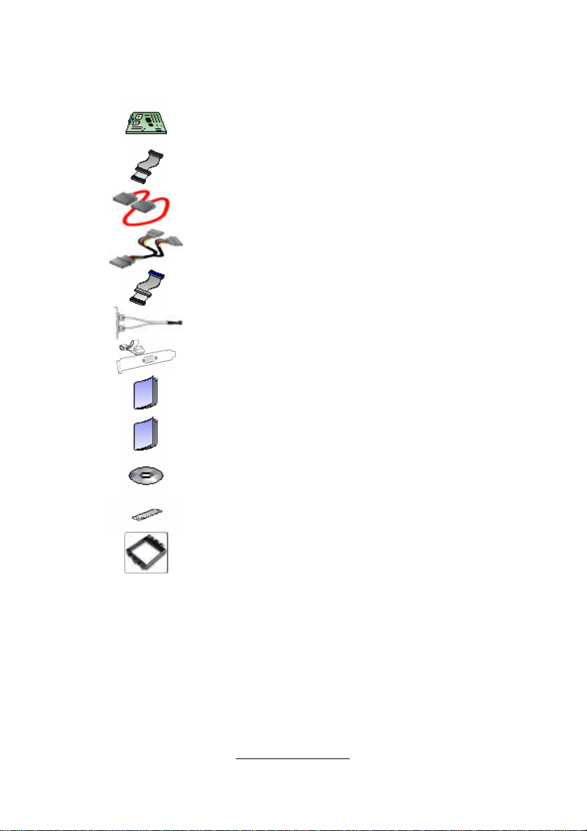
Check the box contents!
The retail motherboard package should contain the following:
1x Thunder K8HM motherboard
1x 34-Pin floppy drive cable
4 x SATA cable
2 x SATA Drive Power Adapter
1 x Ultra-DMA-100/66 IDE cable
1 x USB2.0 cable
1 x COM Port cable
1 x Thunder K8HM User’s Manual
1 x Thunder K8HM Quick Reference Guide
1 x TYAN driver CD
If any of these items are missing, please contact your vendor/dealer for
replacement before continuing with the installation process.
http://www.tyan.com
1 x I/O shield
2 x CPU Retention Frame

4
NOTE
http://www.tyan.com

5
Chapter 1: Introduction
1.1 - Congratulations
You have purchased one of the most powerful server solutions available. The
Thunder K8HM (S3892) is a high-end server motherboard, based on the
ServerWorks BCM5780 & BCM5785 chipsets. It also includes the NS PC87417
Super I/O and SMSC EMC6D 103S Hardware Monitoring chipsets.
This motherboard is designed to support up to two AMD Opteron™ 200 Series
processors and maximum 16GB/32GB of DDR266/333 memory. The S3892 is
ideal for CPU, memory, and network intensive applications required in the HPC
and clustering environments.
Remember to visit TYAN’s Website at http://www.tyan.com. There you can find
information on all of TYAN’s products with FAQs, online manuals and BIOS
upgrades.
1.2 - Hardware Specifications
Processors
• Two uPGA 940-pin ZIF sockets
• Supports up to two AMD OpteronTM
200 Series processors (including dual
core processors)
• Integrated 128-bit DDR memory
controller
Chipset
• ServerWorks BCM5780 + BCM5785
chipsets
• National PC87417 Super I/O chip
Memory
• 128-bit dual channel memory bus
• Total sixteen (16) 184-pin 2.5V DDR
DIMM sockets (8 on CPU1 and 8 on
CPU2)
• Supports PC2100/2700/3200
• Registered, ECC/Non-ECC module
supported
Expansion Slots
• Two (2) PCI Express X16 slots (each
w/ x8 signal)
http://www.tyan.com
Integrated Video Controller
• ATI ES1000 controller
• 32MB DDR frame buffer
Integrated Enhanced IDE
Controller
•Integrated Enhanced IDE Controller
• Single-channel master mode supports
up to two IDE devices
• Supports IDE drives and ATAPI-
compliant devices
Integrated SATA Controllers
• Supports four SATA-II ports at 3.0
Gb/s (BCM5785 Chipset)
• RAID 0/1/5 supported
Integrated LAN Controllers
• Dual GbE LAN (from BCM 5780)
- Embedded in BCM5780
- Two 10/100/1000 RJ-45 LAN ports
w/LED
• One Intel i82551 QM fast Ethernet
controller
- One 10/100 RJ-45 LAN port w/LED

6
• Two (2) PCI-X 133/100MHz slots
• One (1) PCI-X 100MHz slot
• One (1) PCI 32-bit/33MHz, v2.3
compliant slot
• One (1) TYAN “TARO” SO-DIMM
socket
System Management
• Two (2) EMC6D103S hardware
monitoring IC
• Eight (8) 3+1 fan headers support
tachometer monitoring, six (6) of them
with smart FAN control
• Temperature and voltage monitoring
• Watchdog timer support
Integrated I/O
• One floppy connector
• One IDE connector
• Four SATA connectors
• Four USB2.0 ports (2 at rear, 2 via
cable)
• Two COM ports (1 at rear, 1 via cable)
• Tyan 2 x 9 front panel pin header
• Tyan 2 x 6 front panel pin header for
LAN/ID LED
• 2 x 25 connector for optional TYAN
IPMI SMDC
Back Panel I/O Ports
• Stacked PS/2 Mouse & Keyboard
ports
• Stacked 2 USB ports and 1 10/100
RJ45 port
• One 9-pin COM port
• One 15-pin VGA connector
• Two side-by-side RJ-45 ports
Form Factor
• Extended ATX footprint (13” x 12”)
• EPS12V/SSI v3.51 (24+8) power
connectors
- Operating on 32bit/33MHz PCI bus
Optional Modules
• M3291, IPMI 2.0 Remote System
Mgmt card
- Renesas H8S2167 BMC controller
- BT, KCS, Logging support
- IPMI-over-LAN
- Remote power on/off and reset
• M7901/M7902, Ultra 320 SCSI TARO
card
- Adaptec AIC-7901/7902 single/dualchannel Ultra 320 SCSI controller
- Adaptec Host RAID 0, 1, 10 supported
• M9000 SAS/SATA II TARO card
- Adaptec AIC-9405/9410 SAS
controller
- Supports up to 4-port (M9000-5) and
8-port (M9000-10) SAS & SATA running
at 3.0Gb/s
- Adaptec HostRAID 0, 1 & 10
supported
BIOS
• AMI BIOS on 8Mbit LPC Flash ROM
• Serial Console Redirect
• PXE via Ethernet, USB device boot
• SMBIOS 2.3.1, BBS 1.1 compliant
• Headless Operation via serial console
redirect
• 48-bit LBA Support
Power
• Onboard dual 4-phase VRM
• EPS12V/SSI v3.51 (24+8) power
connectors
Regulatory
• FCC Class B (DoC), CE (DoC)
http://www.tyan.com

7
Chapter 2: Board Installation
Precautions: The Thunder K8HM supports SSI, EPS12V type power supplies
(24pin + 8pin) and will not operate with any other types. For proper power
supply installation procedures see page 37.
DO NOT USE ATX 2.x or ATXGES power supplies as they will damage the
board and void your warranty.
How to install our products right… the first time
The first thing you should do is reading this user’s manual. It contains important
information that will make configuration and setup much easier. Here are some
precautions you should take when installing your motherboard:
(1) Ground yourself properly before removing your motherboard from the
antistatic bag. Unplug the power from your computer power supply and
then touch a safely grounded object to release static charge (i.e. power
supply case). For the safest conditions, TYAN recommends wearing a
static safety wrist strap.
(2) Hold the motherboard by its edges and do not touch the bottom of the
board, or flex the board in any way.
(3) Avoid touching the motherboard components, IC chips, connectors,
memory modules, and leads.
(4) Place the motherboard on a grounded antistatic surface or on the
antistatic bag that the board was shipped in.
(5) Inspect the board for damage.
The following pages include details on how to install your motherboard into your
chassis, as well as installing the processor, memory, disk drives and cables.
NOTE
DO NOT APPLY POWER TO THE BOARD IF IT HAS BEEN
DAMAGED.
http://www.tyan.com

8
2.1- Board Image
This picture is representative of the latest board revision available at
the time of publishing. The board you receive may or may not look
exactly like the above picture.
The following page includes details on the vital components of this
motherboard.
http://www.tyan.com
9
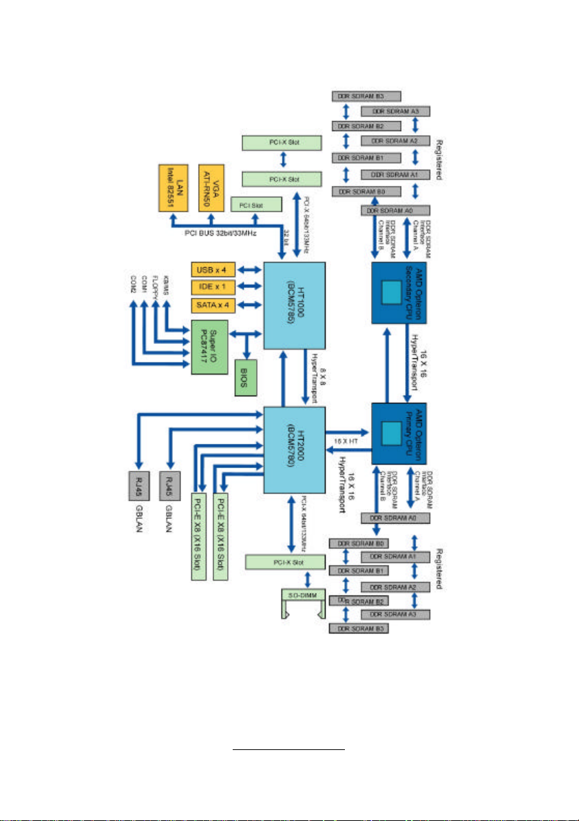
2.2 - Block Diagram
Thunder K8HM (S3892) Block Diagram
http://www.tyan.com
10
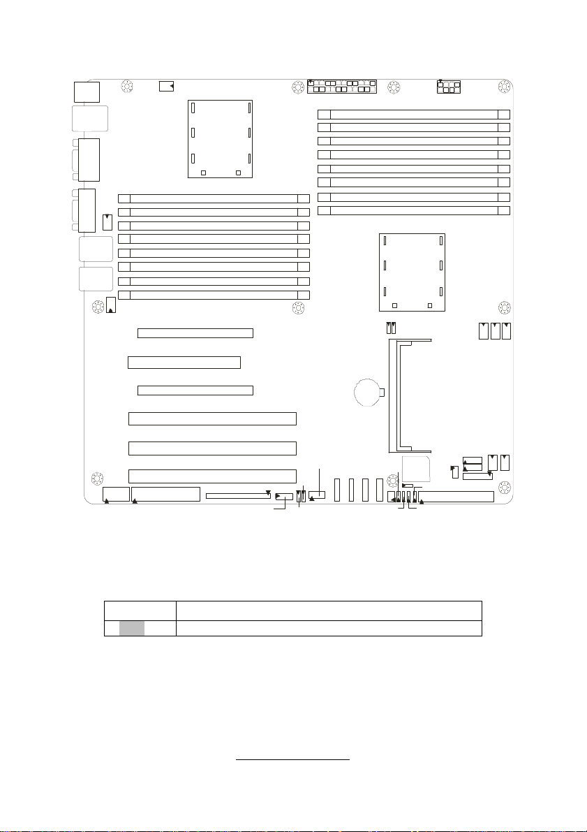
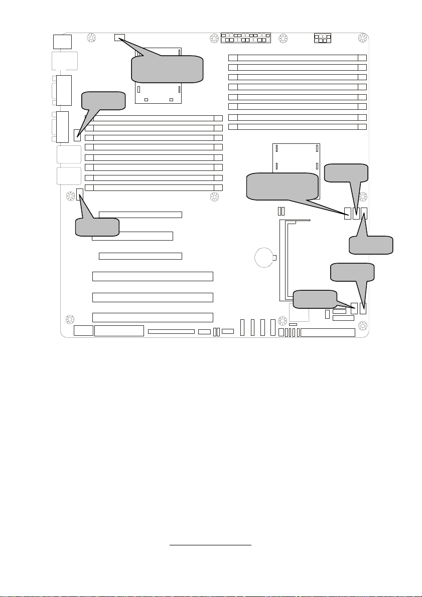
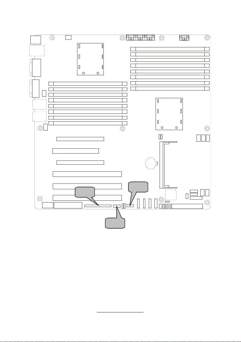
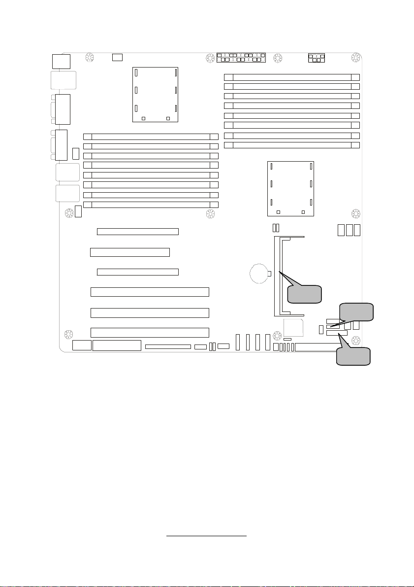
2.3 - Board Parts, Jumpers and Connectors
KB/MS
LAN3
USB x 2
COM1
VGA
LAN2
LAN1
FAN6
FAN5
CPUFAN2
CPU2
CPU2_DIMMA0
CPU2_DIMMB0
CPU2_DIMMA1
CPU2_DIMMB1
CPU2_DIMMA2
CPU2_DIMMB2
CPU2_DIMMA3
CPU2_DIMMB3
PCI-E1
PCI
PCI-E2
PW1
CPU1_DIMMB3
CPU1_DIMMA3
CPU1_DIMMB2
CPU1_DIMMA2
CPU1_DIMMB1
CPU1_DIMMA1
CPU1_DIMMB0
CPU1_DIMMA0
CPU1
JP4
JP3
PW2
CPUFAN1
FAN1
FAN2
COM2
(J9)
FDD (J10)
PCIX-P1
PCIX-S2
PCIX-S1
SMDC (J18)
IPMB (J19)
USB2 (J28)
JP2
JP1
SATA3
SATA2
SATA1
SO-DIMM Socket
JP5
SATA0
J43
JP7
JP10
JP8
JP9
J46
IDE (J44)
J60
J47
J49
This diagram is representative of the latest board revision available at the time of
publishing. The board you receive may not look exactly like the above diagram.
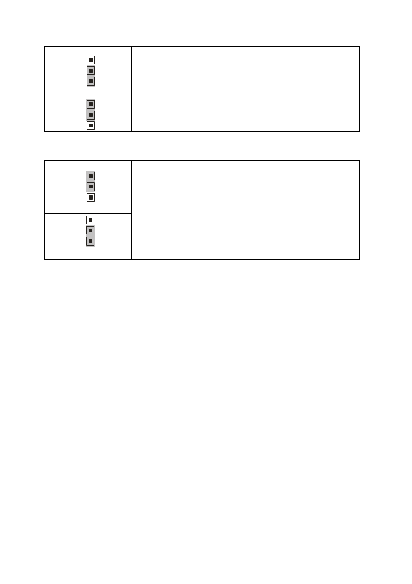
Jumper Legend
©©
©©
OPEN - Jumper OFF, without jumper cover
CLOSED – Jumper ON, with jumper cover
http://www.tyan.com
FAN3
FAN4
11
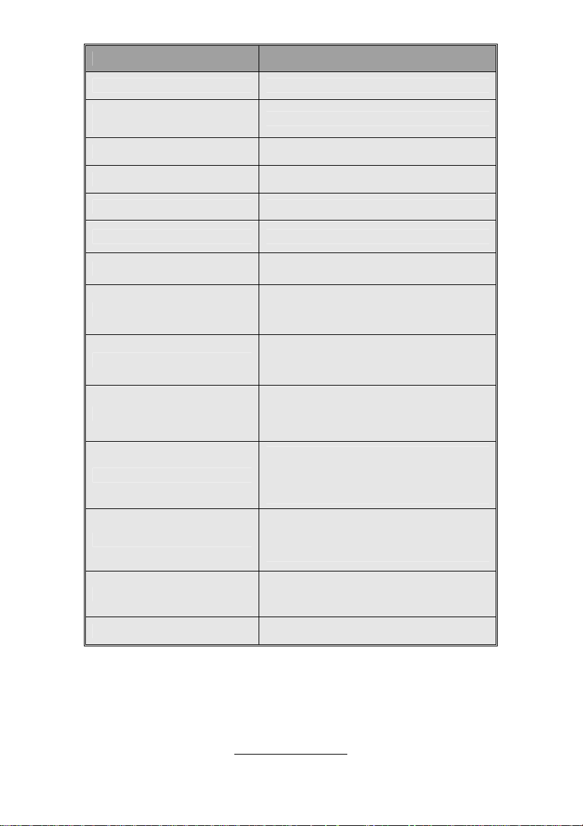
Jumper/Connector Function
FAN5/FAN6 4-pin Fan Connector
CPUFAN1/CPUFAN2/FAN1/
FAN2/FAN3/FAN4
J19 IPMB Connector
J28 USB Front Panel Connector
J30/J39/J40/J41 SATA Connectors
J47 LAN & ID LED and ID Switch Connector
J49 Front Panel Header
JP1/JP2
JP3
JP4
JP5/JP8
4-pin Fan Connector with Speed Control
SMDC/ASF2.0 Select Jumper
(Close 1-2) Default, support ASF 2.0
(Close 2-3) support SMDC card
VGA Enable/Disable Jumper
(Close 1-2) Default, enabled
(Close 2-3) Disabled
LAN3 Enable/Disable Jumper
(Close 1-2) Default, enabled
(Close 2-3) Disabled
PCI-X Mode Select Jumper
(Close 1-2) Default, Based on Card
(Close 2-3) Force to run at PCI mode
(only 66 or 33 MHz)
PCI-X Frequency Select Jumper
JP7/JP9
JP10
J43/J46/J60 Reserved for OEM only
(Close 1-2) Default, based on Card
(Close 2-3) 100MHz or less
Clear CMOS Jumper
(Close 1-2) Default
(Close 2-3) Clear CMOS
http://www.tyan.com
12
FAN2
FAN5
FAN1
FAN6
FAN4
FAN3
CPUFAN2
CPUFAN1
http://www.tyan.com
13
PWM
GND
+12V
Tachometer
1
NC
GND
1 9
2 10
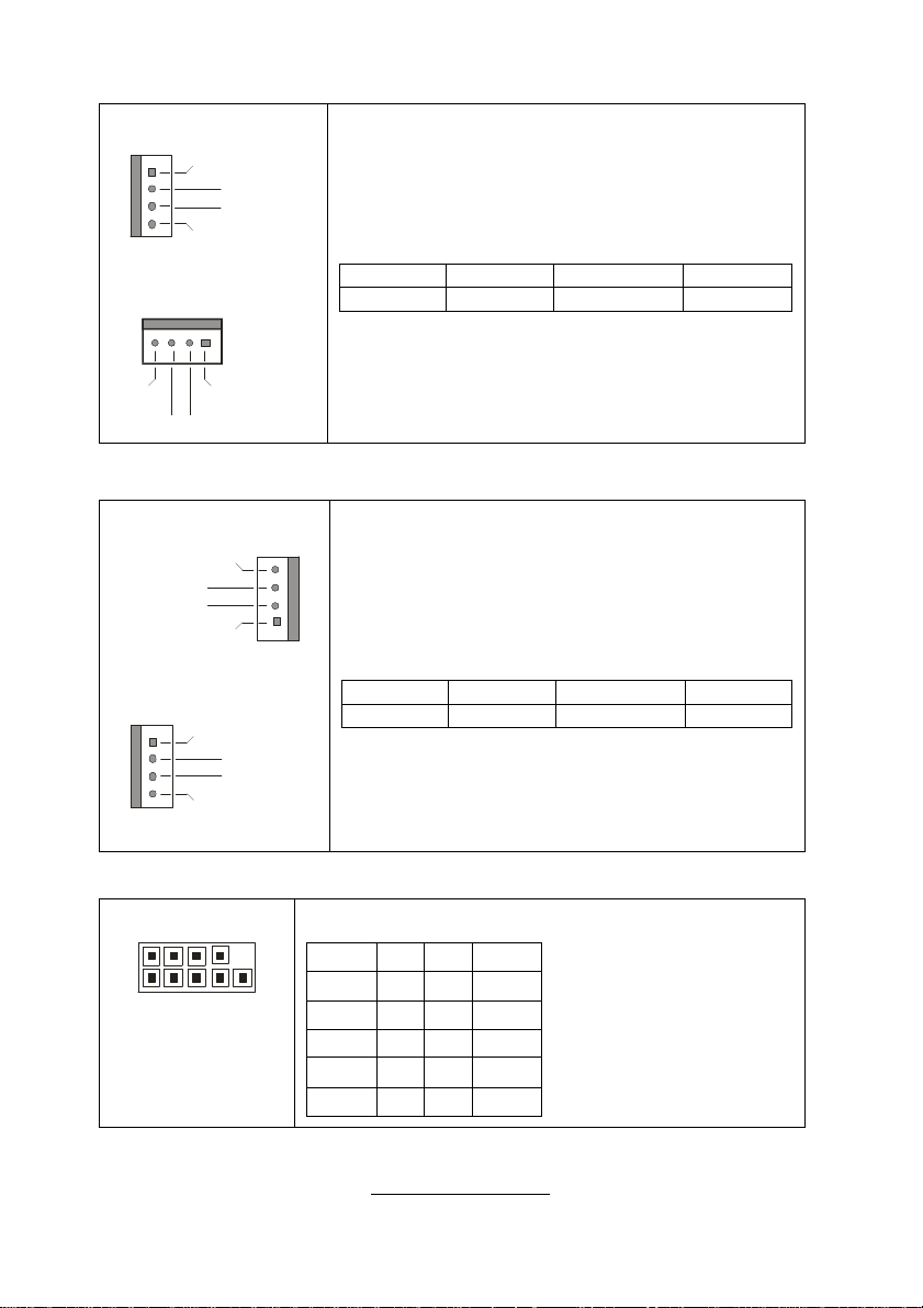
FAN1~4/CPUFAN1~2: 4-pin Fan Connector with Speed Control
CPUFAN1/FAN1~4
1
+12V
Tachometer
Use these headers to connect the cooling fans to
the motherboard to keep the system stable and
reliable.
This connector supports the tachometer monitoring
and auto fan speed control.
CPUFAN2
Pin 1 Pin 2 Pin 3 Pin 4
GND +12V Tachometer PWM
J13: CPUFAN2 J48: CPUFAN1 J50: FAN3
J51: FAN1 J56: FAN4 J57: FAN2
PWM
GND
FAN5/FAN6: 4-pin Fan Connector
FAN5
Tachometer
+12V
GND
FAN6
1
+12V
Tachometer
NC
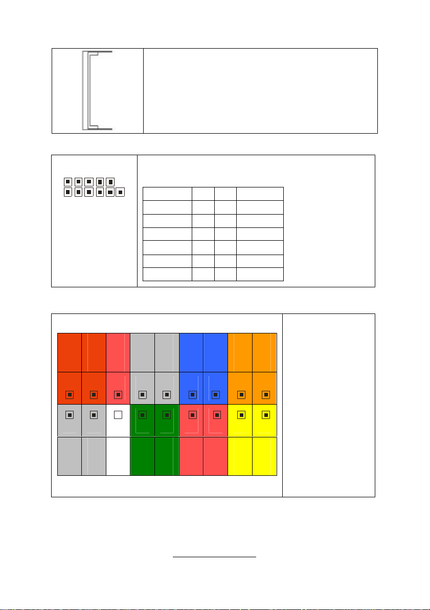
J9: COM2 Header
Use these headers to connect cooling fans to the
motherboard to keep the system stable and
1
reliable.
Pin 1 Pin 2 Pin 3 Pin 4
GND +12V Tachometer NC
J7: FAN5 J8: FAN6
Use these pin definitions to connect a port to COM2.
Signal Pin Pin Signal
DCD 1 2 DSR
RXD 3 4 RTS
TXD 5 6 CTS
DTR 7 8 RI
GND 9 10 KEY
http://www.tyan.com
14
J18 J28 J19
http://www.tyan.com
15
1
1 9
2 10
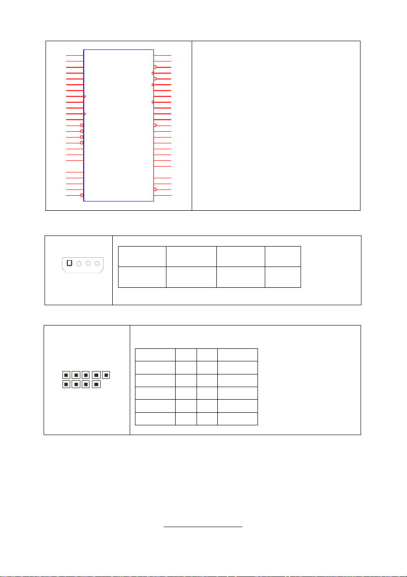
J18: SMDC Connector
J33
1
LAD0
3
LAD2
5
GND1
7
GND2
9
GND3
11
GND4
13
I2C1DA
15
I2C4CLK
17
GND6
19
I2C3DA
21
I2C2CLK
23
5VSB2
25
PWRBTN#
27
RSTBTN#
29
OEMBTN#
31
EXTSMI#
33
CPUNMI#
35
SIO_RXD
37
SIO_TXD
41
SIO_RTS#
43
SIO_CTS#
45
SERIRQ
47
GND12
49
SMALERTB#
CON25X2_M3291
LAD1
LAD3
LFRAME#
PCI_CLK
PCIRST#
I2C1CLK
GND5
I2C4DA
I2C3CLK
5VSB1
I2C2DA
GND7
PCIPME#
COM_TXD
COM_RXD
SOL_CTRL
GND8
COM_RTS#
COM_CTS#
SYSPWRGD
OEMGPIO
BMC_RST#
SMALERTA#
BMC_DET#
J19: IPMB Pin Header
Pin 1 IPMB
Pin 3 IPMB
2
4
6
8
10
12
14
16
18
20
22
24
26
28
30
32
34
36
38
40
44
46
48
50
For connection with Tyan Server
Management Daughter Card (SMDC).
The SMDC connector is only compatible
with Tyan M3291 (SMDC).
Pin 2 GND
DATA
Pin 4 NC
CLK
J28: USB Front Panel Header
Use this header to connect to front panel USB connector.
Signal Pin Pin Signal
USBPWR 1 2 USBPWR
USB3- 3 4 USB4-
USB3+ 5 6 USB4+
GND 7 8 GND
KEY 9 10
http://www.tyan.com
GND
16
J47 J49
J42
http://www.tyan.com
17
1 11
2 12
4
J42: SO-DIMM Socket
Connect SAS/SATA II Daughter Card (compatible with
Tyan M9000-10, M7901/7902 Ultra 320 SCSI “TARO”
card).
J47: LAN & ID LED and ID Switch Connector
J49: Front Panel Header
SMbus Data
SMbus Clock
17 15 13 11 9
18 16 14 12 10 8 6
NC
GND
Use these pin definitions to connect a port to LAN & ID
LED and ID Switch.
Signal Pin Pin Signal
LAN1 LED+ 1 2 LAN1 LEDLAN2 LED+ 3 4 LAN2 LEDLAN3 LED+ 5 6 LAN3 LEDID LED+ 7 8 ID LED1ID S/W+ 9 10 ID S/WNC 11 12 KEY
NMI
5Vsb
Key
GND
WLED-
WLED+
Reset SW+
7 5
GND
GND
HDD LED-
3 1
Power LED-
Power S/W+
HDD LED+
The motherboard
provides one front
panel header for
electrical
connection to the
front panel
2
switches and
LED’s.
Power LED+
http://www.tyan.com
18
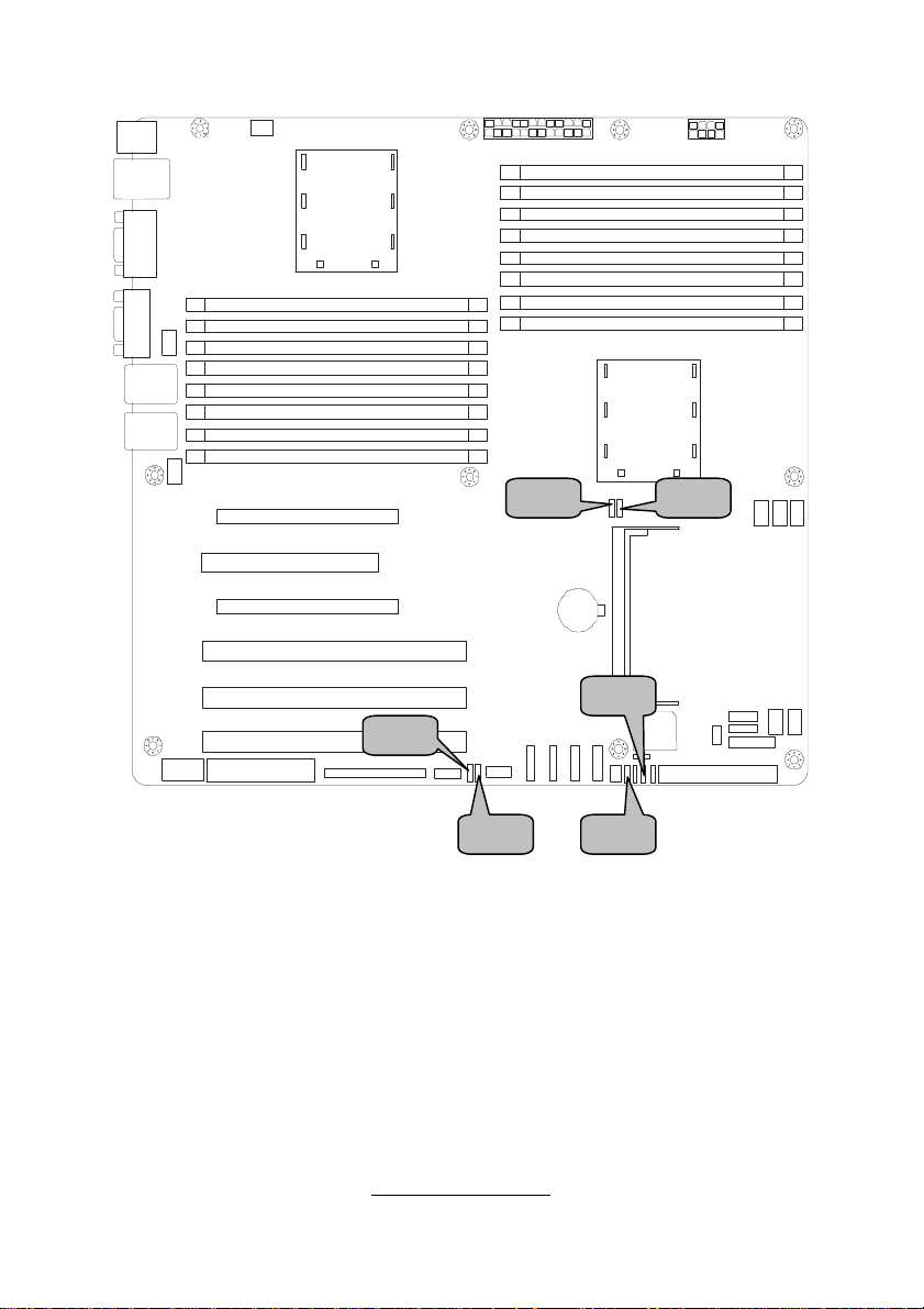
JP8 JP3 JP2 JP5 JP1 JP4
http://www.tyan.com
19
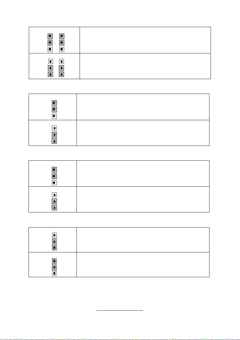
JP1/JP2: SMDC/ASF2.0 Select Jumper
JP1 JP2
131
3
JP1 JP2
131
(Default) - Support ASF2.0
Support SMDC card
3
JP3: VGA Enable/Disable Jumper
1
3
1
3
(Default) - Enable VGA
Disable VGA
JP4: LAN3 Enable/Disable Jumper
1
3
1
3
(Default) - Enable LAN3 (Intel 82551)
Disable LAN3
JP5/JP8: PCI-X Mode Select Jumper
3
1
3
1
(Default) - Based on card
Force to run at PCI mode (only 66 or 33 MHz)
http://www.tyan.com

20
JP10
JP7 JP9
http://www.tyan.com
21
JP7/JP9: PCI-X Frequency Select Jumper
3
1
3
1
(Default) - Based on card
Force to run at 100MHz or less
JP10: Clear CMOS Jumper
3
1
(Clear)
3
1
(Default)
If you have lost your system/setup password or need to
clear the system BIOS settings. You can reset the
CMOS settings by using this jumper.
Power off the system and set JP10 to (2-3) position,
and then power on to boot up the system. The CMOS
will be cleared when the screen is on. Finally shut
down the power, replace JP10 to the default setting (1-
2), power on the system again after done.
http://www.tyan.com
22
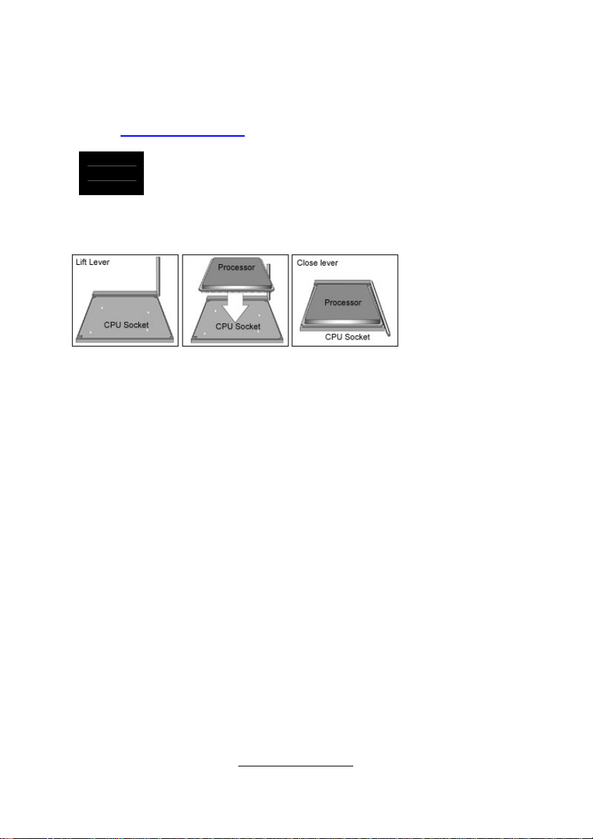
2.4 - Installing the Processor(s)
Your brand new Thunder K8HM supports the latest 64-bit processor technology
from AMD. Only the AMD Opteron
supported with this motherboard. Check our website for latest processor
support. http://www.tyan.com
If using a single processor, it MUST be installed in socket
NOTE
TYAN is not liable for damage as a result of operating an unsupported
configuration.
CPU1. When using a single processor only CPU1 memory
banks are addressable.
™
processor 200 series are certified and
The diagram is provided as a visual guide to help you install socket processors
and may not be an exact representation of the processors you have.
Step 1: Lift the lever on the socket until it is approximately 90o or as far back as
possible to the socket.
Step 2: Align the processor with the socket. There are keyed pins underneath
the processor to ensure that the processor’s installed correctly.
Step 3: Seat the processor firmly into the socket by gently pressing down until
the processor sits flush with the socket.
Step 4: Place the socket lever back down until it locks into place. The
installation is finished.
Repeat these steps for the second processor if you are using two processors.
Take care when installing processors as they have very fragile connector pins
below the processor and can bend and break if inserted improperly.
http://www.tyan.com
23
2.5 - Heatsink Retention Frame Installation
After you are done installing the processor(s), you should proceed with installing
the retention frame and heatsink. The CPU heatsink will ensure that the
processors do not overheat and continue to operate at maximum performance
for as long as you own them. Overheated processors are dangerous to the
motherboard.
The backplate assembly prevents excessive motherboard flexing in the area
near the processor and provides a base for the installation of the heatsink
retention bracket and heatsink.
Because there are many different types of heatsinks available from many
different manufacturers, a lot of them have their own method of installation. For
the safest method of installation and information on choosing the appropriate
heatsink, use heatsinks validated by AMD. Please refer to AMD’s website at
www.amd.com.
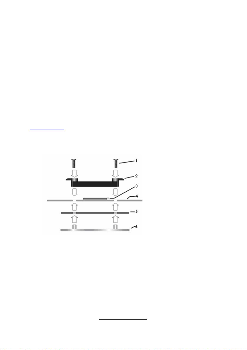
The following diagram will illustrate how to install the most common CPU back
plates:
1. Mounting screws
2. Heatsink retention frame
3. CPU socket
4. Motherboard PCB
5. Adhesive insulator
material
6. Backplate assembly
NOTE: Please see next
section for specific
instructions on how to install
mounting bracket.
http://www.tyan.com
24
2.6 - Thermal Interface Material
Always check with the manufacturer of the heatsink &
NOTE
processor to ensure the Thermal Interface material is
compatible with the processor & meets the manufacturer’s
warranty requirements
http://www.tyan.com
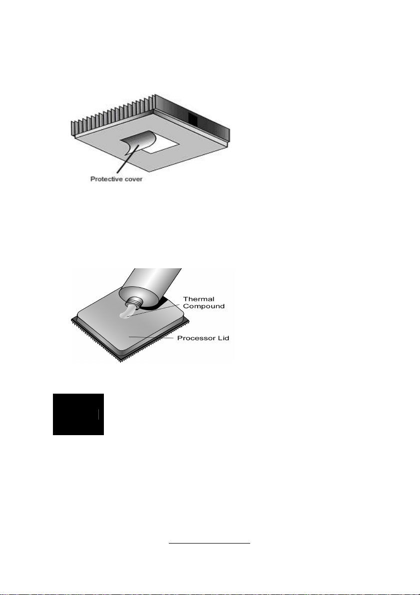
There are two types of
thermal interface materials
designed for use with the
AMD Opteron processor.
The most common material
comes as a small pad
attached to the heatsink at
the time of purchase. There
should be a protective cover
over the material. Take care
not to touch this material.
Simply remove the protective
cover and place the heatsink
on the processor.
The second type of interface
material is usually packaged
separately. It is commonly
referred to as ‘thermal
compound’. Simply apply a
thin layer on to the CPU lid
(applying too much will
actually reduce the cooling).
25
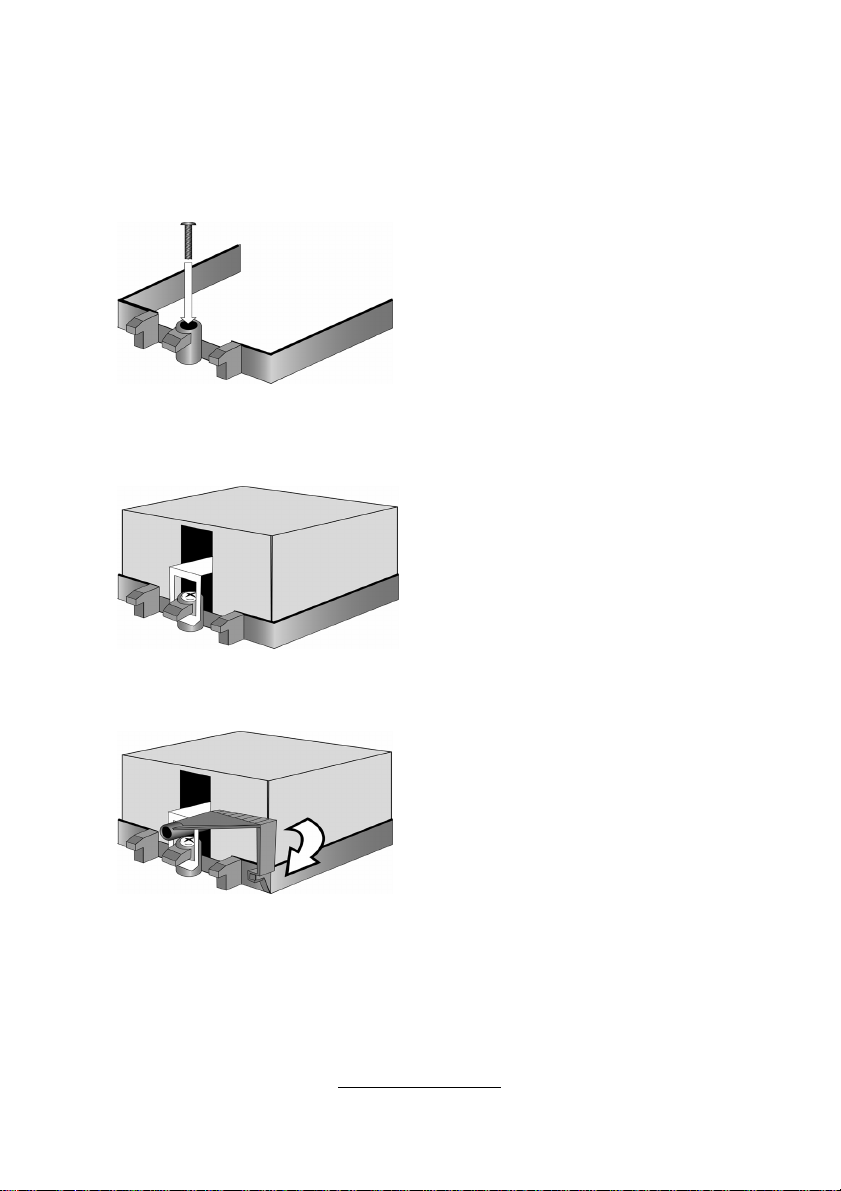
2.7 - Heatsink Installation Procedures
Type A: CAM LEVER (TYPE) INSTALLATION
1. After placing backplate and
interface material under motherboard
place heatsink retention frame on top
of motherboard. Align plastic retention
bracket screw holes with CPU backplate standoffs.
Tighten screws to secure plastic
retention bracket. Repeat for the other
side. DO NOT OVER TIGHTEN.
2. After tightening screws secure
metal clip to plastic retention bracket
center tab. Repeat for the other side
of heatsink.
3. After securing metal clip to plastic
retention bracket center tab, push
down on plastic clip to lock plastic clip
to side tab.
http://www.tyan.com
26
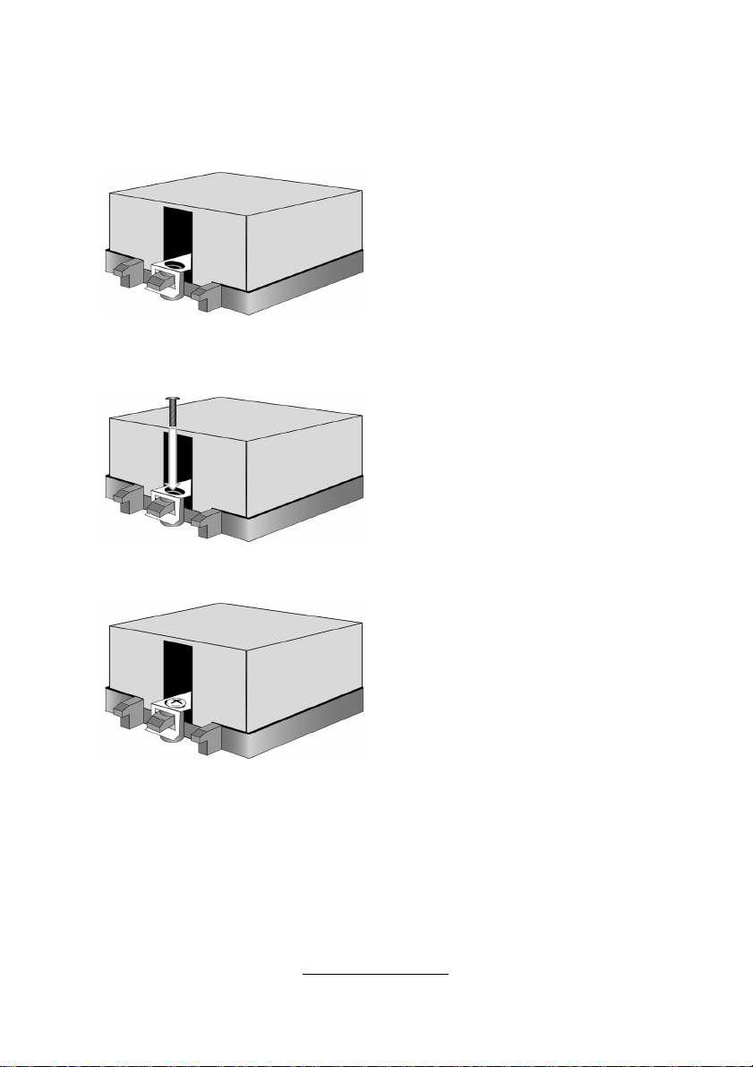
2. Insert screw through metal clip.
de.
Type B: SCREW RETENTION TYPE HEATSINK
1. After placing CPU back-plate and
adhesive interface material under
motherboard, place heatsink
retention frame on top of
motherboard. Align heatsink retention
frame screw hole with backplate
assembly standoffs. Place heatsink
inside plastic retention bracket. Place
metal clip over retention frame tab.
Repeat for other side.
BE SURE METAL CLIP IS LOCKED
ONTO RETENTION FRAME TAB.
3. Tighten screw through metal
clip. Repeat on the other si
DO NOT OVER TIGHTEN.
http://www.tyan.com

27
Finishing Installing the Heatsink
After you have finished installing the heatsink onto the processor and socket,
attach the end wire of the fan (which should already be attached to the heatsink)
to the motherboard. The following diagram illustrates how to connect fans onto
the motherboard.
Once you have finished installing all the fans you can connect your drives (hard
drives, CD-ROM drives, etc.) to your motherboard.
http://www.tyan.com
28
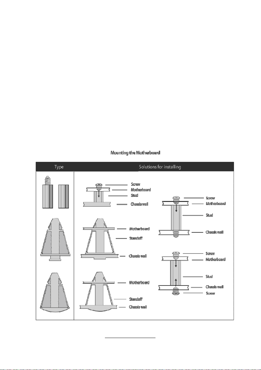
2.8 - Tips on Installing Motherboard in Chassis
Before installing your motherboard, make sure your chassis has the
necessary motherboard support studs installed. These studs are usually
metal and are gold in color. Usually, the chassis manufacturer will pre-install
the support studs. If you are unsure of stud placement, simply lay the
motherboard inside the chassis and align the screw holes of the
motherboard to the studs inside the case. If there are any studs missing,
you will know right away since the motherboard will not be able to be
securely installed.
Pay attention when installing board in chassis. Some components are
near the mounting holes and can be damaged.
Some chassis’ include plastic studs instead of metal. Although the plastic
studs are usable, TYAN recommends using metal studs with screws that will
fasten the motherboard more securely in place.
Below is a chart detailing what the most common motherboard studs look
like and how they should be installed.
http://www.tyan.com
29
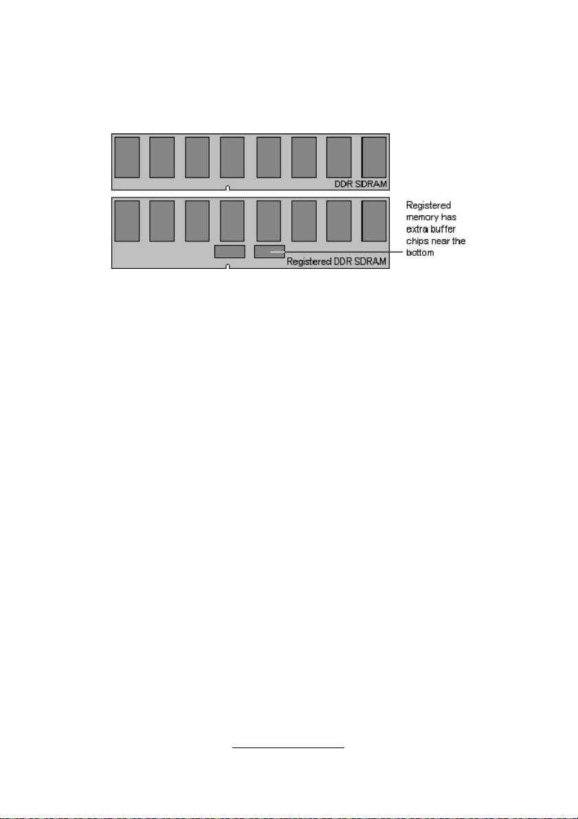
2.9 - Installing the Memory
Before attempting to install any memory, make sure that the memory you
have is compatible with the motherboard as well as the processor.
The following diagram shows common types of DDR SDRAM modules:
Key points to note before installing memory into Thunder K8HM:
For optimal dual-channel DDR operation, always install memory in pairs
beginning with CPU1_DIMMA3 and CPU1_DIMMB3. Memory modules of
the same type and density are required for dual-channel DDR operation.
Mismatched memory may cause system instability.
When the DIMMs are not fully populated, the system can support 256MB,
512MB, 1GB and 2GB of PC2100/2700/ Registered memory modules.
However, if 8 DIMMs and 16 DIMMs are populated for single and dual
CPU operation respectively, the system can only support up to PC2100.
All installed memory will be automatically detected.
The Thunder K8HM S3892 supports up to 32GB of memory.
http://www.tyan.com
30
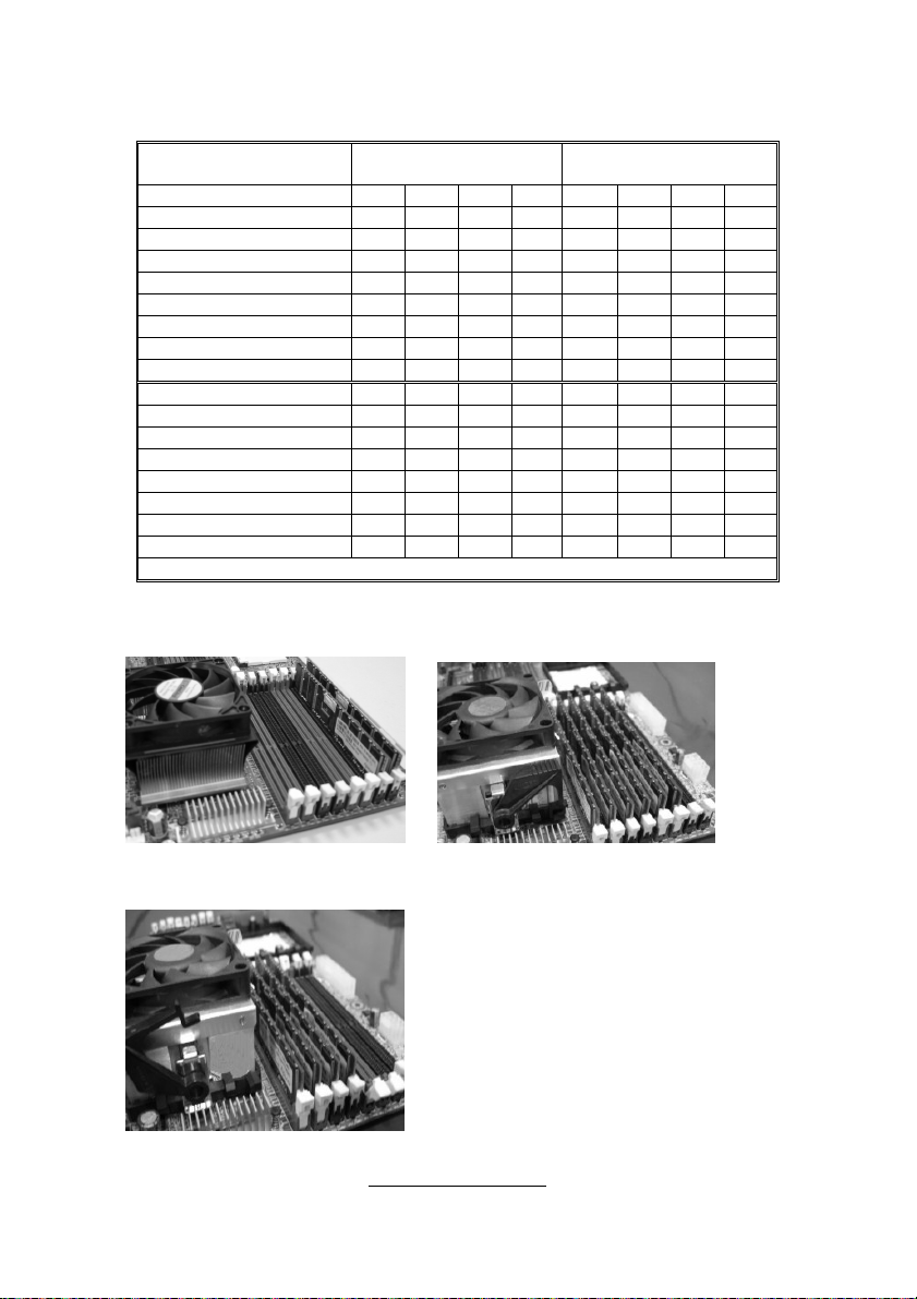
To correctly install the memory in pairs (DIMMA# + DIMMB#), refer to the
following table for supported population options.
Population Option 1 2 3 4 5 6 7 8
CPU1_DIMMA0 x x x x x x
CPU1_DIMMB0 x x x x x x
CPU1_DIMMA1 x x x x x x
CPU1_DIMMB1 x x x x x x
CPU1_DIMMA2 x x x x
CPU1_DIMMB2 x x x x
CPU1_DIMMA3 x x x x
CPU1_DIMMB3 x x x x
CPU2_DIMMA0 x x x
CPU2_DIMMB0 x x x
CPU2_DIMMA1 x x x
CPU2_DIMMB1 x x x
CPU2_DIMMA2 x x
CPU2_DIMMB2 x x
CPU2_DIMMA3 x x
CPU2_DIMMB3 x x
(Note: X indicates a populated DIMM slot)
Single CPU Installed
(CPU1 only)
Dual CPU installed
(CPU1 and CPU2)
When install 2 DIMMs When install 6 DIMMs
When install 4 DIMMs
http://www.tyan.com
 Loading...