

Page 1

Tyan S1836
Thunder 100
Motherboard User’s Manual
Revision 2.30
Copyright © Tyan Computer Corporation, 1998. All rights reserved. No part of this
manual may be reproduced or translated without prior written consent from Tyan
Computer Corp.
All registered and unregistered trademarks and company names contained in this
manual are propery of their respective companies including, but not limited to the
following.
AMIBIOS is a trademark of American Megatrend Incorporated.
Windows is a trademark of Microsoft Corporation.
IBM, PC, AT, PS/2 are trademarks of IBM Corporation.
INTEL, Pentium II, Celeron are trademarks of Intel Corporation.
S1836 Thunder 100 is a trademark of TYAN Computer Corporation.
Information contained in this publication has been carefully checked for accuracy and
reliability. In no event will Tyan Computer be held liable for any direct or indirect,
incidental or consequential damage, loss of use, loss of data, or other malady resulting
from errors or inaccuracies of information contained in this manual. The information
contained in this document is subject to change without notice.
PRINTED IN USA
Page 2

T able of Contents
1. Introduction....................................................................... 4
Overview............................................................................................... 4
Icons..................................................................................................... 5
Hardware Specifications/Features....................................................6
Software Specifications......................................................................8
T echnical Support...............................................................................8
Returning Merchandise for Service................................................. 9
2. Board Installation.............................................................. 11
Unpacking............................................................................................11
Installation........................................................................................... 11
Setting Jumpers...................................................................................2 4
3. Onboard Resource Settings.............................................. 2 5
Quick Reference for Jumpers.............................................................2 5
Map of Motherboard Jumpers..........................................................2 6
Hardware CMOS & Password Reset................................................2 8
Soft Power Connector.........................................................................31
Speaker Connector Installation.........................................................3 1
Hardware Reset Switch Connector Installation..............................3 1
W avetable Upgrade............................................................................3 1
External SMI.........................................................................................32
Chassis Intrusion Alarm Connector ................................................. 3 2
Audio Connectors.............................................................................. 32
CMOS RTC...........................................................................................33
Flash EEPROM....................................................................................3 3
RAM Installation................................................................................ 3 3
Cache Memory .....................................................................................34
Intel Ethernet Setup and Use............................................................ 35
Creative Labs Sound Drivers Installation Note..............................4 9
Frequently Asked Questions............................................................ 51
4. BIOS Configuration........................................................... 55
Main Setup...........................................................................................5 6
Advanced CMOS Setup.................................................................... 61
Chipset Setup...................................................................................... 6 6
Power Management Setup.................................................................7 2
Plug and Play Setup............................................................................7 6
Peripheral Setup.................................................................................. 8 1
Supervisor and User Security ............................................................84
Page 3

Language Utility..................................................................................85
Flash Writer Utility ..............................................................................85
5. System Resources............................................................. 8 7
Beep Codes..........................................................................................8 7
Troubleshooting System Problems..................................................8 8
Displayed Error Messages................................................................ 89
Appendix 1 - CPU Retention Module Options............................................... 91
Appendix 2 - Glossary .......................................................................................93
Page 4
Chapter 1
Introduction
chapter 1
Introduction
Overview
The Thunder 100 family is a quality, high performance motherboard designed
for Intel Pentium II microprocessors. This motherboard utilizes the Intel 440BX
(S1836DLU, S1836DLUAN) or 440GX (S1836DLUAN-GX) AGPsets and can
support CPU speeds of 233MHz through 450MHz, and host bus speeds of
66MHz to 100MHz.
The motherboard, with built-in AGP slot, provides high performance capabilities that are ideal for a wide range of demanding applications such as CAD,
CAM, CAE, desktop publishing, 3D animation, and video production.
This integrated system board achieves high reliability with numerous features
and yet is small enough to be supported in an Extended ATX form factor. Some
of the features included are onboard dual channel PCI PIO, Bus Master IDE
and UltraDMA/33, onboard floppy controller, onboard dual channel SCSI,
RAIDport II, onboard Creative Vibra 16XV sound, onboard Intel Ethernet, and
onboard high speed I/O (Ethernet and Sound controllers on DLUAN models
only).
With I/O and drive controller support built onboard, the one AGP slot, six PCI
and one ISA slots (one shared, seven usable) are free for numerous add-on
expansion cards.
http://www.tyan.com
4
Page 5
Remember to take a look at TY AN Computer’s web site located at
http://www.tyan.com. There you can find information on all of TYAN’ s
products along with F AQs, distributors list, drivers, and BIOS setting explanations.
Icons
In order to help you navigate this manual and set up your system, we have
added several icons to our format.
This icon alerts you to particularly important details regarding
!
the setup or maintenance of your system. This icon often
important!
vital paragraphs in a chapter, you should always read every word in the text.
Failing to do so can lead to exasperation and expense.
appears next to information that may keep you from damaging
your board or system. While we will often point out the most
INTRO
1.
2.
3.
procedure
Wherever possible, we have included step-by-step instructions
for setting up your system, which are indicated by this icon.
However, it is in your best interest to read an entire section (and
perhaps the entire manual) before you begin to fiddle with your motherboard.
warning
While we have alerted you to potential dangers in several places
in the manual with this icon, these warnings should not be
regarded as the whole of your safety regimen. Never forget that
computers are electrical devices, and are capable of delivering a shock. Prevent
damage to yourself and to your board: always ensure that your system is
turned off and unplugged whenever you are working with it, and that you are
equipped with a static safety device.
S1836 Thunder 100
5
Page 6

Chapter 1
Introduction
Hardware Specifications/Features
Processor Information · Two SEC slots (Slot One type)
· 66MHz to 100MHz bus support
· Pentium II 233-600MHz
· Supports Celeron CPUs in single
mode
Chipset Information · Intel 440GX AGPset (S1836DLUAN-GX)
· Intel 440BX AGPset (S1836DLU/DLUAN)
· Intel PIIX4e controller
· SMC 932FR Super I/O chipset
· DEC 21152-AB PCI Bridge
Voltage and Power · ATX power supply connector
Information · +12V power source for DC fan onboard
· 3.3V DRAM support
· Utilizes GTL+ bus to reduce power
consumption and EMI
Main Memory · Up to 2048MB* onboard (for GX model)
· Up to 1024MB onboard (for BX models)
· Four 168-pin DIMM sockets
· Supports 100MHz SDRAM with
SPD, and SDRAM+ECC
· Supports 66MHz SDRAM with SPD
with 66MHz CPU clock only
System Management
··
· National LM79 and LM75 ASICs with
··
onboard alarm for monitoring temperature,
supply voltages, and fan speed
··
· Intel LANDesk Client Manager
··
software
··
· Chassis intrusion detection capable
··
* See TYAN website for list of compatible memory modules.
http://www.tyan.com
6
Page 7

Expansion Slots · One 32-bit AGP slot
· Six 32-bit PCI Bus Master slots
· One 16-bit ISA slot
· One shared, seven usable
Physical Dimensions · Extended ATX design
· 13 inches x 12 inches
· IO shield compatible with Intel
Providence (included)
BIOS Information · AMI Plug and Play flash BIOS
· Deep Green, Energy Star , ACPI, Y ear 2000,
and PC98 compliant (the Adaptec AIC-7895
SCSI chip is NOT PC98 compliant)
· Yellow LED for sleep mode
Disk Drive & System I/O · T wo PCI bus mastering EIDE
channels
· Supports EIDE CD-ROMs
· PIO Mode 3 & 4 (up to 17MB/sec DTR)
· UltraDMA/33 bus mastering mode
(up to 33MB/sec DTR)
· Support for two floppy drives (Mode
3 and 2.88MB supported)
· T wo serial ports (16550 UAR T s)
· One ECP/EPP parallel port
· One IR (InfraRed) I/O interface port
· T wo USB rev 1.2 ports
· One PS/2 mouse port
· One PS/2 keyboard port
· Wake-on LAN header (requires ATX
2.01 power supply)
INTRO
Onboard UltraWide SCSI · Adaptec AIC-7895 dual channel UltraW ide
SCSI
· T wo 68-pin high density UltraW ide SCSI
ports
· One 50-pin SCSI-2 port
· Adaptec Ultra SCSI BIOS
S1836 Thunder 100
7
Page 8

Chapter 1
Introduction
· RAID 0 and 1 support using optional
Adaptec ARO-1130CA PCI card
(RAIDport II)
Creative Labs Sound · V ibra 16XV Midi audio chip
(S1836DLUAN models only) · ATX Joystick, Audio in, Speaker,
Microphone connectors
Onboard Ethernet · Intel 82558 10/100 Ethernet
(S1836DLUAN models only) onboard
· Full Wake-on functionality (see
power supply requirements above)
· One RJ-45 ATX connector
Software Specifications
OS ·Operates with MS-DOS, Windows
3.x, Windows for W orkGroup 3.x,
Windows 95, W indows 98, W indows
NT , OS/2, Novell Netware, Solaris,
and SCO Unix
T echnical Support
If a problem arises with your system, you should turn to your dealer for help
first. Your system has most likely been configured by them, and they should
have the best idea of what hardware and software your system contains.
Hence, they should be of the most assistance. Further, if you purchased your
system from a dealer near to you, you can actually bring your system in to
them to have it serviced, instead of attempting to do so yourself (which can
have expensive consequences).
If your dealer is unable to assist you,
try our web page, http:// www.tyan.com
user newsgroup, alt.comp.periphs.mainboard.tyan
http://www.tyan.com
8
Page 9

Returning Merchandise for Service
During the warranty period, contact your distributor or system vendor FIRST
for any product problems. This warranty only covers normal customer use and
does not cover damages incurred during shipping or failure due to the
alteration, misuse, abuse, or improper maintenance of products.
For Resellers Only:
A receipt or copy of your invoice marked with the date of purchase is required
before any warranty service can be rendered. You can obtain service by calling
the manufacturer for a Return Merchandise Authorization (RMA) number. The
RMA number should be prominently displayed on the outside of the shipping
carton and the package should be mailed prepaid, or hand-carried to the
manufacturer. TYAN will pay to have the board shipped back to you.
INTRO
S1836 Thunder 100
9
Page 10

This page is intentionally left blank.
10
http://www.tyan.com
Page 11
chapter 2
Board Installation
Unpacking
The motherboard package should contain the following:
· S1836DLU, S1836DLUAN or S1836DLUAN-GX motherboard
· One 40-pin IDE and 34-pin floppy cable pack
· One 9-pin Com port cable
· User’s manual
· One Ultra Wide SCSI cable
· One regular SCSI cable
· T wo retention modules
· One A TX I/O Shield
· One System Management & Driver CD; includes complete drivers for
LAN and audio controllers and manual and installation instructions for
Creative Vibra 16XV.
Installation
You are now ready to install your motherboard. The mounting hole pattern of
the Thunder 100 matches the ATX system board specifications. Your chassis
S1836 Thunder 100
11
Page 12

Chapter 2
Board Installation
should be that of a standard ATX motherboard form factor.
How to install our products right...the first time.
1.
2.
What’s the first thing I should do?
3.
The first thing you should do is read this user’s manual. It contains important
procedure
information which will make configuration and setup much easier.
The next step is to properly ground yourself. First, unplug the power from your
computer case and then touch the metal casing of the power supply or any
metal part on the computer case. This will discharge any electricity from your
body. Take the motherboard out of the cardboard box and static bag, holding it
by its edges, and place it on a grounded anti-static surface, component side
up. Inspect the board for damage.
DO NOT APPL Y POWER TO THE BOARD IF IT HAS BEEN DAMAGED!
!
important!
Press down on any of the socket ICs if it appears that they are not properly
seated (the board should still be on an anti-static mat). Do not touch the
bottom of the board. Remember, don’t take any electronic device out of its
protective bag until you are ready to install it into the computer case. If you
don’t ground yourself, you risk zapping the motherboard or adapter card.
Subsequent problems may not arise immediately because electrostatic discharge damage, unlike physical damage, causes the device to fail over time.
Install the motherboard into your case.
Follow the instructions provided by the case manufacturer for proper installation guidelines. TYAN recommends that you use only one screw to hold down
the motherboard. The rest of the mounting holes should be used for the plastic
standoffs. If your case does not have a hole for a standoff, simply cut off the
bottom of the plastic standoff so that the flat portion rests on the metal. The
adapter cards and the screws holding them down will keep your board flat. The
fastening screw should not short any of the traces on the motherboard. Make
certain that you do not overtighten the screw , as it will damage the motherboard and possibly break internal traces in the surrounding area. The hole you
should use is located at the top-center of the board where the adapter cards
are fastened to the case.
http://www.tyan.com
12
Page 13
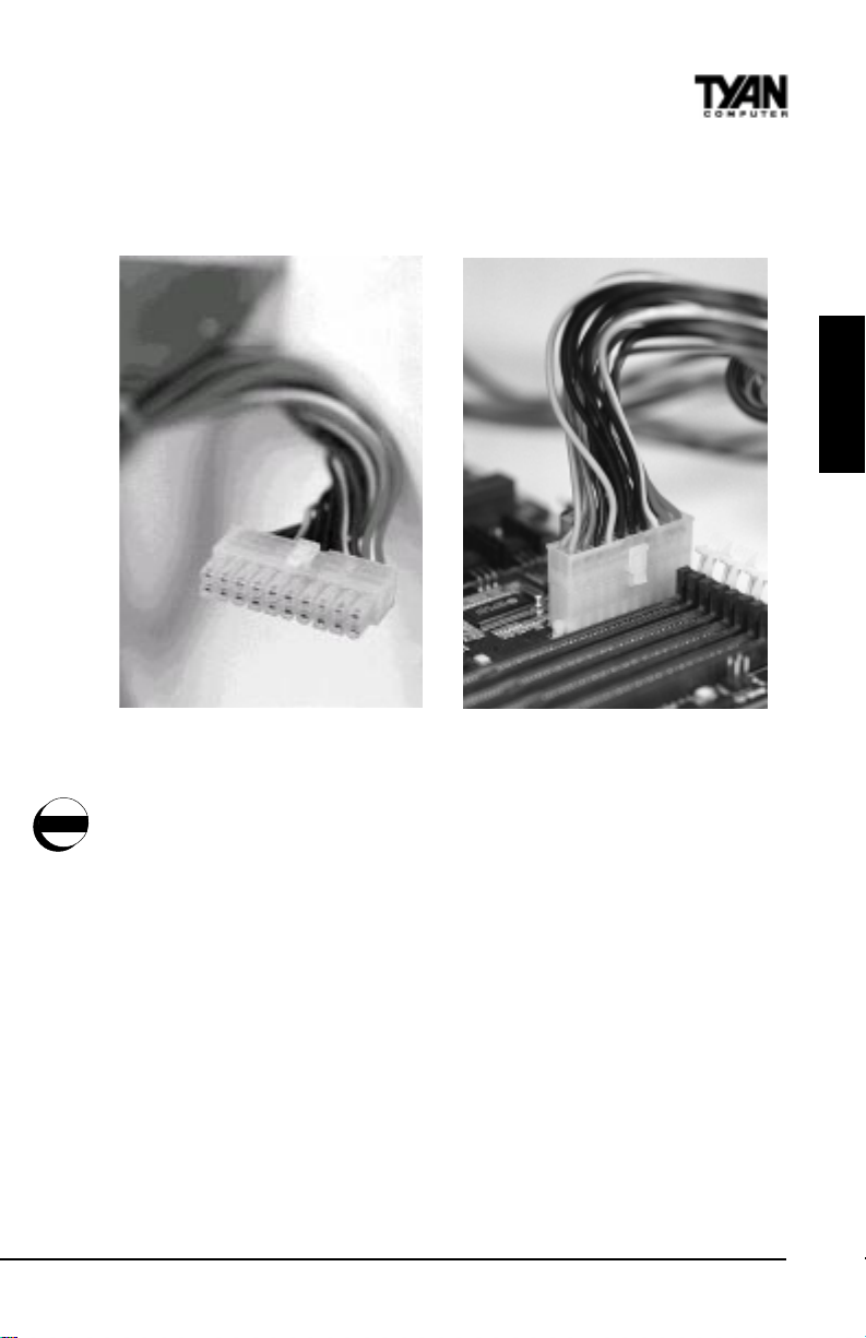
Plug in the power connector as shown.
The photos below show the ATX power connector before (Figure 1) and after
(Figure 2) it has been plugged in.
INSTALL
Figure 1
Figure 2
The plastic clip on the power connector should lock over the plastic tab on the
onboard connector. You shouldn’t be able to plug the power connector in any
warning
other way but just to be safe, make sure it looks like Figure 2 above. Make
absolutely certain that you do not miss any pins because, if you do, you will
void your warranty and cause damage to yourself or your motherboard when
you turn the system on. After connecting the power, make sure the connector
is seated firmly into its socket so it will not become loose or fall off when the
computer is jostled or moved. Note: T yan recommends using an ATX power
supply that conforms to industry standard revision 2.01.
S1836 Thunder 100
13
Page 14
Chapter 2
Board Installation
Next, connect your IDE cables (if you’re using IDE hard drives).
Figure 3
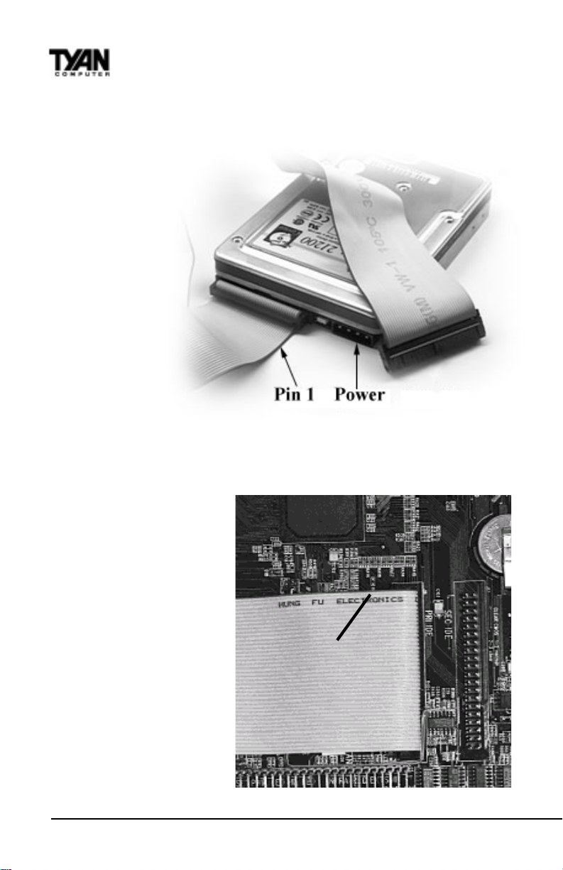
On all TYAN motherboards, the colored stripe on the cable always faces
towards the rear of the case (towards the ATX connectors).
In Figure 3 you can see
how the IDE cables should
look when they are
connected to your hard
drive. Notice how Pin 1
(denoted by a red stripe) is
connected so that it is next
to the power connector of
the drive. In most cases,
this is the proper way of
connecting your IDE cable
to the hard drive. Figure 4
shows the IDE cable
properly connected to the
motherboard.
Contact your hard disk
drive manufacturer or
documentation for more
Pin 1
Figure 4
http://www.tyan.com
14
Page 15
information.
Some symptoms of incorrectly installed HDDs are:
• Hard disk drives are not auto-detected: may be a Master/Slave
problem or a bad IDE cable. Contact your vendor.
• Hard Disk Drive Fail message at bootup: may be a bad cable or
lack of power going to the drive.
• No video or beeps on bootup: usually means the cable is on
backwards.
• Hard drive lights are constantly on: bad IDE cable or defective
drives/motherboard. Try another HDD.
• Hard drives do not power up: check power cables and cabling.
May also be a bad power supply or IDE drive.
Now that you have installed your IDE drives, your floppies are next.
INSTALL
Figure 5
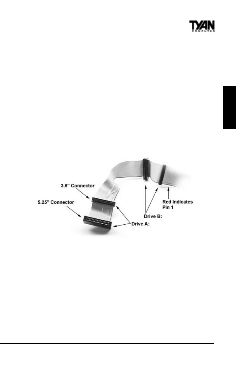
Pin 1 on the floppy cable is usually denoted by a red or colored stripe down
one side of the cable (see Figure 5 above). Most of the current floppy drives
on the market require that the colored stripe be positioned so that it is right
next to the power connector. In most cases, there will be a key pin on the cable
which will force you to connect the cable properly .
Drive A: is usually attached to the end of the cable with the twist in it. Drive B:
is usually connected to the middle of the cable. Refer to your installation
instructions or call your dealer if you are unsure about attaching floppy drives.
Refer to Figure 5 for a detailed anatomy of the floppy cable. Remember, you
can only have 2 floppy drives connected at any given time.
S1836 Thunder 100
15
Page 16
Chapter 2
Board Installation
On all TYAN motherboards, the colored stripe on the cable always faces
towards the rear of the case (towards the ATX connectors), as with the IDE
cables. Please refer to your documentation for proper installation, or see Figure
4 on page 14.
Some symptoms of incorrectly installed floppies are:
• Floppy drives are not detected: usually caused by faulty cables, backward
cables, or a bad floppy or motherboard. Try another single floppy drive to
verify the problem or try another cable. Also, check to see if the onboard
floppy is enabled in the BIOS.
• Floppy Drive Fail message at bootup: the cable, floppy, or motherboard
may be faulty. Try another cable or floppy drive to verify.
• Light on the floppy is on constantly: a dead give-away that the cable is on
backwards. Reverse the cable at the motherboard end and try again.
Next are the Com and Printer ports.
Warning: When plugging in your keyboard and mouse, or when plugging
anything into a serial or Com port, make sure that the power is off. Connecting
!
these devices and ports while the power is on is called “hot plugging,” and
important!
may damage your system.
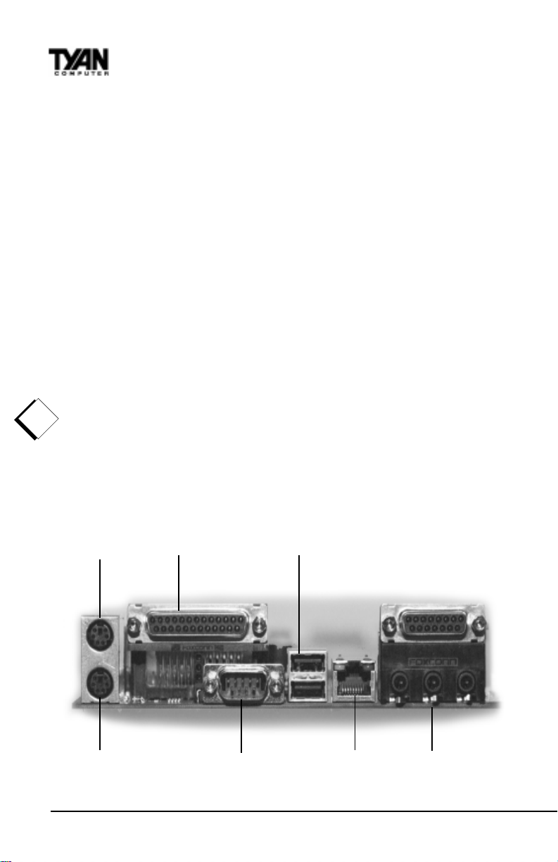
Figure 6 below shows the ATX double row connectors on this board. The Com
and Printer ports, as well as the other ports, are labeled.
PS/2 Mouse LP1 USB
PS/2 Keyboard Com1 LAN* Sound*
Figure 6
http://www.tyan.com
16
Page 17
(* S1836DLUAN and S1836DLUAN-GX only)
Note: Only TY AN cables will work on this motherboard. If you are using an
existing case with old cables, your system will not function properly . Use only
TYAN-approved cables.
Connecting the USB and PS/2 ports.
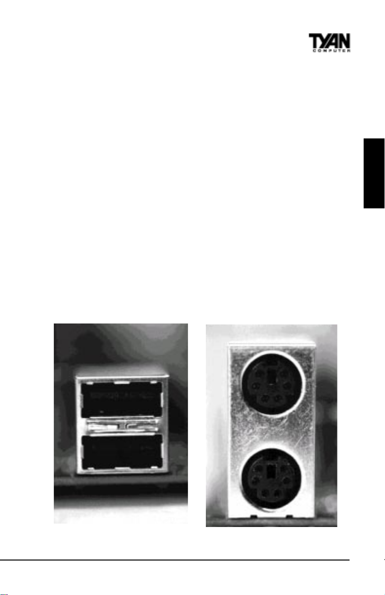
This board includes ports for USB, PS/2 mouse, and PS/2 keyboard devices.
The location of these ports is shown in Figure 6 above. Note that, for this
board, the PS/2 mouse port is the upper PS/2 port, and the PS/2 keyboard port
is the lower PS/2 port.
The PS/2 connectors are probably quite familiar to you. The USB connectors,
however, may be foreign. The USB (Universal Serial Bus) is a versatile port.
This one port type can function as a serial, parallel, mouse, keyboard, or
joystick port. It is fast enough to support video transfer, and is capable of
supporting up to 127 daisy-chained peripheral devices. Close-ups of the USB
connector, as well as of the USB and PS/2 ports, are on the following page.
Figure 7 shows the USB ports and Figure 8 the PS/2 ports.
INSTALL
S1836 Thunder 100
Figure 7 Figure 8
17
Page 18

!
important!
Chapter 2
Board Installation
Installing your add-in cards is relatively simple but...
there are a few rules you need to follow when plugging in a card. In order to
assure proper operation and a quick installation, adhere to these guidelines:
• If you are going to install a PCI-Bus interface card on your system,
be aware that any one of the two PCI slots can support a Master
or Slave device.
• NEVER force a card into a slot. If it doesn’t fit, look at the socket
on the computer to make sure there are no wires or other
obstructions to the slot.
• NEVER plug an ISA card into a PCI slot or a PCI card in an ISA
slot. You will void your warranty and damage your system board if
you do this.
• When plugging the card in, especially when installing long cards,
try to push the entire card in at one time. Don’t force one end of
the card into the socket first and then the other. This will create a
rocking motion between the card and the slot and it will damage the
pins within the socket.
• Make sure that the cards are seated securely into the slots.
• Before turning on the system, make sure no cards are touching
each other or are shorting.
If you follow these basic guidelines, there shouldn’t be any problems with
installation. However, if you do encounter any problems, have a qualified
professional install your cards for you or contact your card manufacturer.
Remember, always read the manuals and installation notes that come with the
adapter cards. They contain important information which will help you install
the components right, the first time.
Next, you need to install your memory.
Since TY AN boards are manufactured with performance in mind, you should
use add-in components that match. Some DIMM modules may seem to be
high quality because of name or feel but that does not guarantee real-world
usability. Some cheaper or OEM memory may have brand-name components,
but they may contain inferior or substandard parts which do not meet the
critical tolerances our products require. Because of this, your memory may not
work correctly in a TY AN board though it may work well in a competitor’s
board. This is because many of our competitors do not adhere to the strict
tolerances required for high performance. If you buy a TYAN board, you are
getting the best system available. T o make installation easy and trouble free,
http://www.tyan.com
18
Page 19
get high quality parts. Some brands we recommend are Advantage Memory ,
Corsair Microsystems, Millenium, Kingston Memory , QesT ec Incorporated,
Unigen, Micron Technology, and Crucial Technology. These DIMMs have
proven to be very stable on our boards and perform extremely well.
Figure 9
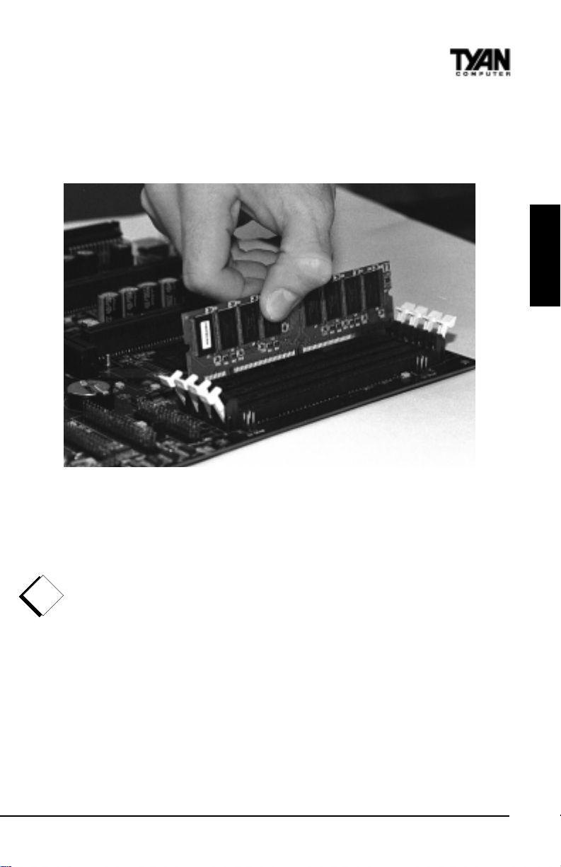
T o install your DIMMs, line your module up so that the pins fit into the slot.
There is only one way that your DIMM can fit properly . Make sure that the
short row of pins is lined up with the short gap in the DIMM slot. Figure 9
shows how to sit the DIMM into its slot. To insert the DIMM, push down
vertically on the module with even force, as shown in the photo. Do not shove
one end in first; doing so will bend the DIMM pins.
!
important!
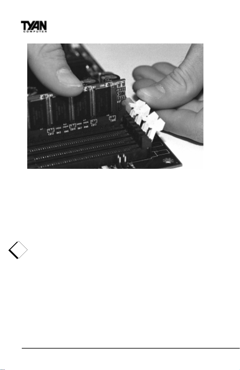
T o lock the DIMM into place, push the plastic clips on either end of the slot
onto the notches in the ends of the DIMM (see Figure 10 on the following
page). T o remove your DIMM, simply pull the clips back, and pull up on the
module.
INSTALL
S1836 Thunder 100
19
Page 20
Chapter 2
Board Installation
Figure 10
Place the DIMMs in an anti-static bag as soon as you remove them to avoid
static damage.
Finally, install your CPU.
Pentium II processors (233 through 450MHz) can be used on the Thunder 100.
Please refer to pages 28-30 for the correct CPU jumper settings for your board.
Remember:
· The CPU is a sensitive electronic component and it can easily be damaged
!
important!
by static electricity. Do not touch the CPU pins with your fingers.
· Before the CPU is installed, the motherboard must be placed on a
flat surface. Y ou should be able to insert the CPU with minimal, but
firm, pressure. Do not press down hard on the CPU.
Currently, two types of cooling mechanisms are produced for Pentium II
processors: active (figure 11) and passive (figure 12). These two types of
cooling methods essentially perform the same function. The active cooler is
equipped with a cooling fan and heat sink, while the passive cooler is simply a
larger heat sink with no fan. The type of cooler used has no effect on performance, and both types can be installed in the Pentium II slot on the Thunder
100 board.
20
http://www.tyan.com
Page 21
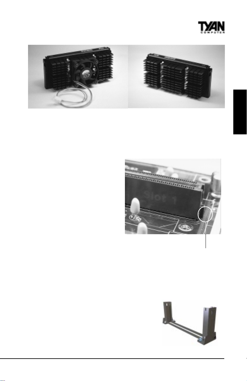
Figure 1 1 Figure 12
Installing CPU Retention Modules
Installation of a Pentium II processor requires a CPU retention module, which
is first secured onto the motherboard. Tyan offers a variety of retention
mechanisms for the different CPU
types. See Appendix 1 for details.
T o attach the retention module,
place the motherboard on a flat
surface. Locate the key pin on one
end of the Pentium II slot on the
board. Then carefully line up the
key notch on the retention module
with the key pin on the Pentium II
slot (the key pin on the Pentium II
slot indicates the correct
orientation of the CPU).
Drop the retention module (Figure
14 on the following page) down
over the Pentium II slot so that the retention module sits flat against the
motherboard. Tighten the screws in a clockwise manner to secure the module
to the board. Warning: Do not overtighten the screws as you may damage the
module and/or the motherboard.
Figure 13 - Pentium II Slot Connector
and Key Pin
INSTALL
Installing the CPU with Active Cooling
When the retention module is securely installed,
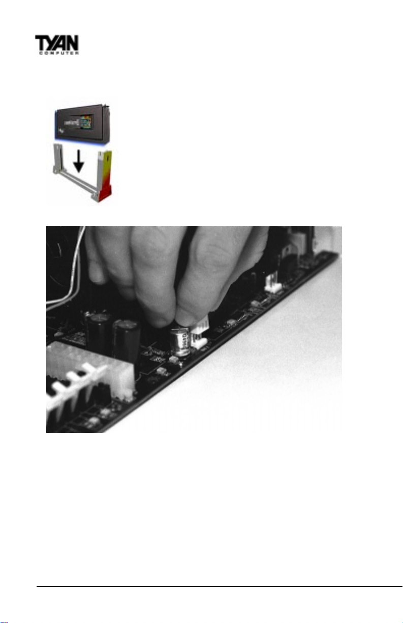
you are ready to plug in the CPU. Press down firmly
on the CPU until you hear a “click” (see Figure 15
on the next page). This clicking sound indicates
S1836 Thunder 100
21
Figure 14
Page 22
Chapter 2
Board Installation
that the CPU is fully locked into the retention module. If you have an active
cooler, you will also need to connect the CPU’s cooling fan cable to the cooling
fan power connector on the board.
Locate the cooling fan connector (e.g. F AN1) on the motherboard. Plug the CPU’s cooling fan cable into the cooling
fan connector on the board. There will be a plastic clip assembly similar to that of the A TX power connector that will
force you to connect the fan cable correctly (see Figure 16
below).
Figure 15
Figure 16
Installing the CPU with Passive Cooling
The installation of the CPU with passive cooling differs only slightly from that
of the active. Your passive cooling package should contain one CPU retention
module, one heat sink retention bracket with mounting locks, two mounting
attachments, and one heat sink lock.Install the retention module as explained in
the previous section.
The heat sink mount (Figure 17) has two pins on the bottom and four pins on
the top. Notice that the bottom two pins are of different sizes. The size of the
http://www.tyan.com
22
Page 23
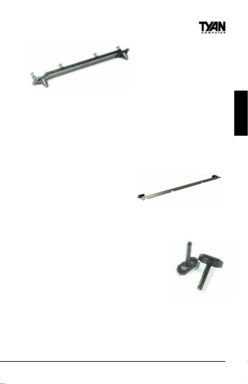
pins and the holes in the motherboard will determine the correct
orientation. When the bracket is
correctly installed, the four pins
on top will be right next to the
Figure 17
Pentium II CPU slot.
Insert the heat sink mount into the holes on the motherboard. When the
bracket is properly inserted into the holes on the motherboard, you will hear a
clicking noise.
Align the CPU with the CPU retention module. Make sure the heat sink is lined
up with the heat sink mount bracket. If you put the CPU in the wrong way , you
may damage the CPU, the motherboard, and/or the CPU socket. Slowly press
down on the CPU module until the CPU locks into place. Y ou will hear a
clicking noise when the CPU is locked securely into the module.
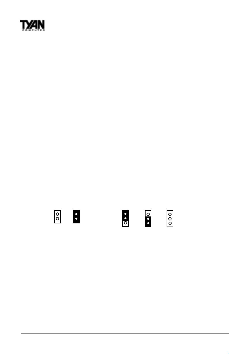
The heat sink lock (Figure 18) has four
notches which will correspond to the
four pins on the heat sink mounting
bracket. Gently slide the lock between
Figure 18
the heat sink and the heat sink mounting bracket until both sides of the lock are firmly secured. A clicking sound will
be heard when the lock is securely fastened to the heat sink mounting bracket.
T o remove the lock from the heat sink mounting
bracket, gently press the ends of the locks inward and
pull.
INSTALL
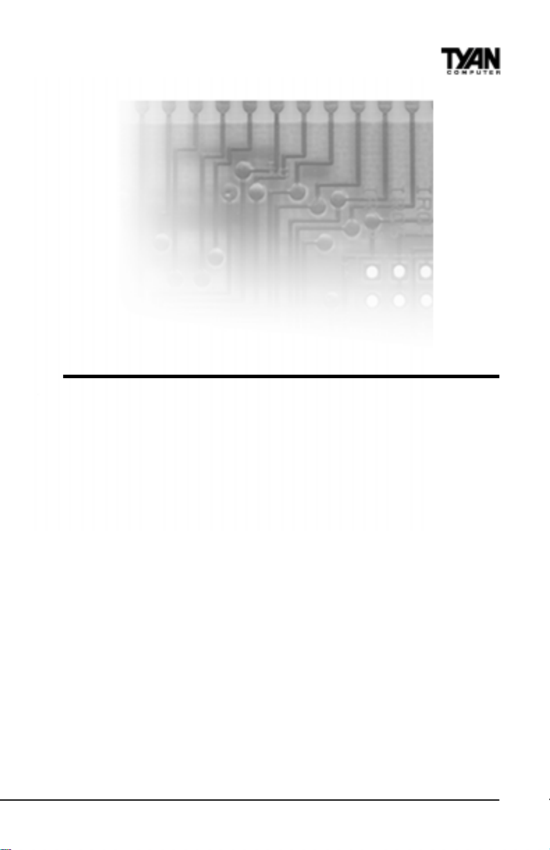
Lock the heat sink mount to the board by inserting
the two mounting locks (Figure 19) into the pins of
the heat sink mounting bracket which are now below
the mainboard. There will be a click when the locks are
securely fastened.
Figure 19
Removing the CPU.
T o remove the CPU, move the locks to the center of the CPU. A click will be
heard when the CPU has been unlocked. Gently pull up on the CPU, taking
care not to bend the motherboard or the CPU retention module.
T o remove the lock from the retention module, gently press the ends of the
locks inward and pull.
S1836 Thunder 100
23
Page 24
Chapter 2
Board Installation
You are done.
Other than checking the jumper settings and cable connections and putting
the case back on, you are done. Installing a new motherboard may sound
difficult, but by following these directions, you should have a fairly uneventful
time installing our products. If you do encounter problems, your dealer will be
able to help you, or you can consult one of our many technical support
resources (see page 8).
Setting Jumpers
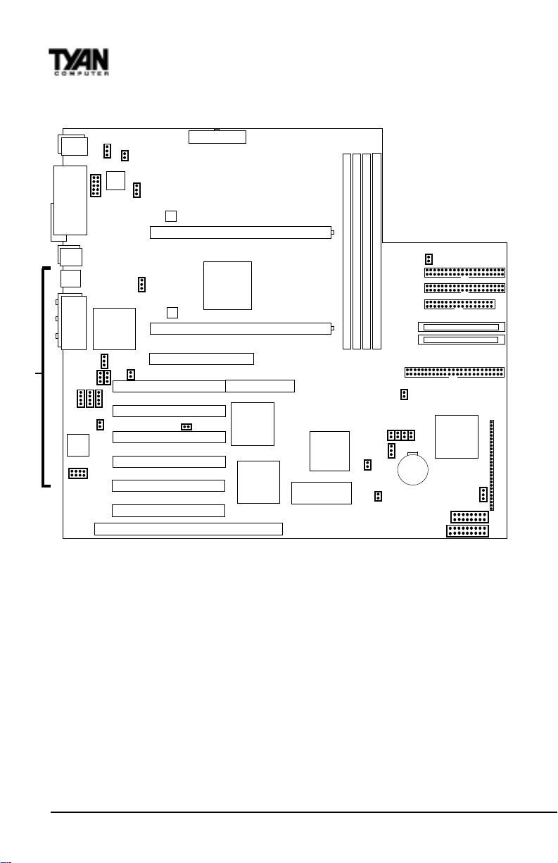
In this manual, the terms “closed” and “on” are used when referring to
jumpers (or jumper pins) that are active; “open” and “off” are used
when referring to jumpers (or jumper pins) that are inactive. Jumpers
and pins are connected by slipping the blue or black plastic jumper
connector overtop of two adjacent jumper pins. The metal rod inside
the plastic shell bridges the gap between the two pins, completing the
circuit. See the drawings below for examples of “on” and “off” pins
and jumpers.
2 pin jumpers
off on
3 (or more) pin jumpers
1-2 2-3 open
1
2
3
24
1
2
3
1
2
3
http://www.tyan.com
Page 25
chapter 3
Onboard Resource Settings
Quick References for Jumpers
The tables on the following pages will help you set the jumpers for CPU speed,
SCSI settings, and external connector pin assignments, among others. The miniature motherboard maps will help you locate the jumpers on your board. A fullpage map of the motherboard can be found on the next page.
S1836 Thunder 100
25
Page 26
Chapter 3
Onboard Resource Settings
Map of Motherboard Jumpers
COM1
**
Keyboard
1
Mouse
FAN3
1
Printer Port
COM2
USB1
USB2
Ethernet
Speaker out Line in Mic in
port
Joystick
82558
Ethernet
JP22
1
JP33
11
1
JP18
JP19
JP20
JP16
Creative
Vibra
16XV
JP17
1
LM79
Intel
chip
1
1
JP32
JP31
JP26
1
1
FAN1
FAN2
PCI slot 1
PCI slot 2
PCI slot 3
PCI slot 4
PCI slot 5
PCI slot 6
ATX power supply
LM75
CPU slot 2 (Slot One type)
LM75
or GX chip
CPU slot 1 (Slot One type)
AGP port
JP30
ISA slot 1
Intel
82443BX
RAID port
digital
21152-AB
chip
SMC 932FR
Super I/O
chip
Intel
82371EB
chip
AMIBIOS
DIMM bank 4
DIMM bank 3
DIMM bank 2
DIMM bank 1
JP25
JP46
JP9
JP3
JP29
JP10
1
JP11
3 volt
lithium
battery
J8
Secondary IDE connector
Wide SCSI Channel B
Wide SCSI Channel A
Narrow SCSI Channel A
JP12
JP44
Primary IDE connector
Floppy connector
Adaptec
AIC-7895P
SCSI chip
1
FAN4
Chassis Fan
JP45
J10
1
The tiny “1”s next to jumpers of 3 pins or more indicate the position of pin 1 for
that jumper.
** The following components are NOT included in the S1836DLU:
1) Ports - Ethernet / Joystick / Sound
2) Chips - Intel 82558 Ethernet Chip / Creative Vibra 16XV
3) Jumpers - JP16 - 20 and JP31 - 33
http://www.tyan.com
26
Page 27
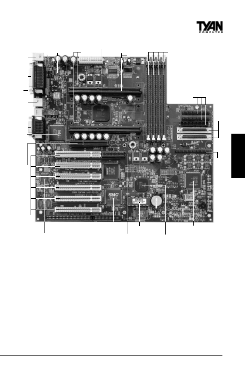
Double row ATX connectors
LM79
Intel 443BX/GX
LM75
2 SEC slots
4 DIMM slots
2 Wide SCSI channels
IDE and Floppy
connectors
ONBOARD
Intel 82558 Ethernet
AGP port
1 ISA slot
Creative Labs Vibra 16XV
6 PCI slots
SMC 932FR
RAID port
AMIBIOS
1 Narrow SCSI channel
Adaptec AIC-7895
Intel PIIX4e
S1836 Thunder 100
27
Page 28

Chapter 3
Onboard Resource Settings
CPU Settings for 66MHz Bus
deepSkcolCtluM9PJ01PJ11PJ21PJ
zHM332
zHM662
zHM003
zHM333
5.3xNOFFOFFONO
4xFFONONONO
5.4xFFONOFFONO
5xFFOFFONONO
CPU Settings for 100MHz Bus
deepSkcolCtluM9PJ01PJ11PJ21PJ
zHM053
zHM004
zHM054
zHM005*
5.3xNOFFOFFONO
4xFFONONONO
5.4xFFONOFFONO
5xFFOFFONONO
*Due to CPU unavailability, this speed has not been tested.
Note on 66/100 MHz bus speeds: You must have a 100MHz processor to run at
a bus speed of 100MHz. If you have a 100MHz processor, do not try and run it
at 66MHz. The bus speed is BIOS selectable. Y our processor will automati-
cally run at the correct bus speed because the BIOS default is Auto.
CMOS Settings
tluafeDSOMCteseR
3PJ
2-13-2
Hardware CMOS & Password Reset
If you have been locked out of your system because you forgot your
password or set the CMOS incorrectly , follow the instructions below.
1. Power off the system
2. Set jumper JP3 to pins 2 and 3 (see previous page for
location of JP3).
http://www.tyan.com
28
Page 29
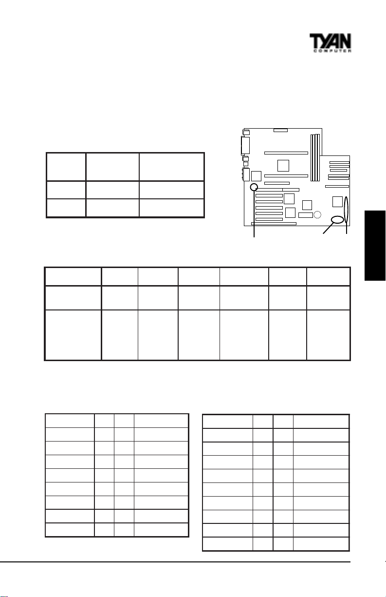
3. Wait for 2 seconds, then return jumper JP3 to pins 1 and 2.
4. Power on the system again.
By following this procedure, you will erase your password and reset the
SCSI IRQ Settings CMOS to the BIOS defaults.
Line Out Sound Settings
pmaerPhtiw
)tluafed(
23PJ
33PJ
2-13-2
2-13-2
pmaerPtuohtiw
JP32, JP33
JP44
JP45
J10
J10 External Connector Pin Assignments
sniP2-101-661-3102-8132-2272-42
noitcnuF
tnemngissA
rewoP
ffO/nO
ffO/nO
DNG=2
RI
rotcennoC
rewoP=1
CCV=6
XRRI=8
DNG=9
XTRI=01
edoM=11
-=51
+=61
DELDDHDELrewoP
DNG=81
+=02
teseR
hctiwS
DNG=22
teseR=32
rekaepS
CCV=42
rekaepS
-=72
JP45 Pinout JP44 Pinout
2x9 External Connector Proprietary Server Mgmt Connector
(for OEM use only)
CCV12 DELrewoP
DELDDH34 DELpeelS
dnuorG56 ffO/nOrewoP
teseR78 dnuorG
CCV901hctiwSIMS
evieceRRI1121CCV
dnuorG3141tcennoCoN
timsnarTRI5161CCV
tcennoCoN7181tcennoCoN
#IMSREVRES12KLCBMSMN
DNG34 DNG
niFFO/NO56 ATADBMSNM
KOPL78 KLNUYEK
TUOIMN901V3BSMN
#TESR_PF1121DNG
DNG3141tcennoCoN
ERUCES5161DNG
TNISIHC7181tcennoCoN
tcennoCoN9102DNG
ONBOARD
lanretnI=62
S1836 Thunder 100
29
Page 30
Chapter 3
Onboard Resource Settings
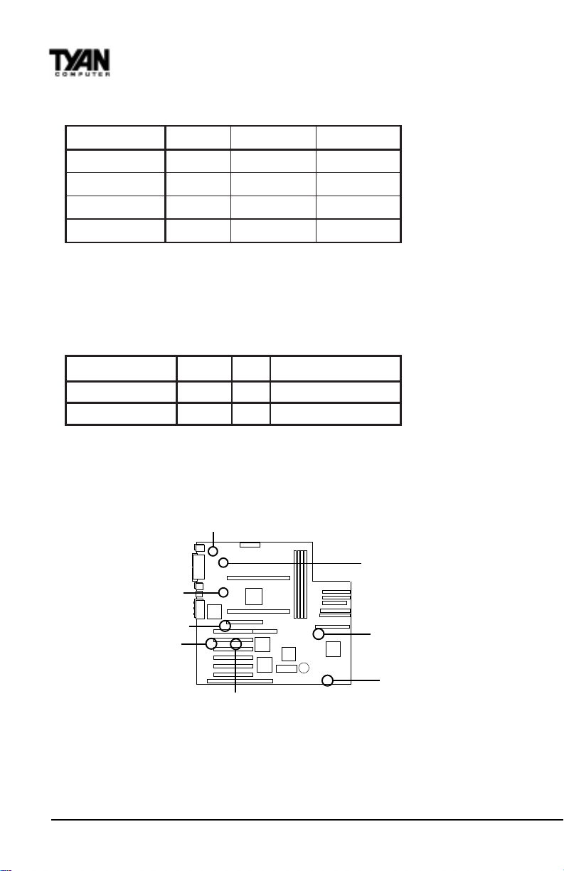
Enabling and Disabling Features
repmuJdelbanE)tluafed(delbasiD
*tenrehtE
*dnuoS
ISCS
egdirBICP-ICP
13PJFFONO
61PJFFONO
92PJFFONO
03PJFFONO
* Ethernet and Sound NOT on 1836DLU (default settings disabled).
Other Pin Assignments
12 3
4-1NAF DNGCCVrotinoMnaF
)NALno-ekaW(22PJ V5ybdnatSDNG)hgiHevitcA,nOrewoP(ekaW
FAN1
JP31
JP16
FAN3
FAN1
JP29
FAN4
JP30
http://www.tyan.com
30
Page 31

Soft Power Connector
The Soft Power Connector is located on pins 1 and 2 of jumper block J10. The
Thunder 100 uses the PIIX4e chip for power management, including turning on
and off the system. If the Power Button Function option in the Power
Mangement Menu is set to On/Off (which is the default), pressing the power
button once, after the BIOS has booted up, will turn the system on and off. If
the Power Button Function option is set to Suspend, pressing the power
button once will wake the system or send it in to Suspend mode. In this case,
you cannot turn the system off unless you shut down through the Windows
operating system or you hold the power button down for four seconds.
Speaker Connector Installation
The Thunder 100 provides a 4-pin header to connect the speaker. The speaker
is connected to pins 24-27 of jumper block J10.
Hardware Reset Switch Connector
Installation
The Reset switch on your case’s display panel provides you with the Hardware Reset function, which is the same as power on/off. The system will do a
cold start after the Reset button is pushed. The Reset switch is a 2-pin
connector and should be installed on pins 22 and 23 of jumper block J10.
ONBOARD
W avetable Upgrade
The Creative Labs Vibra 16XV chip can be upgraded to produce wavetables
using a peripheral card. This card will have a cable which needs to be connected to JP17. Contact a Creative Labs distributor or
dealer for availability of their peripheral card.
S1836 Thunder 100
31
Page 32
Chapter 3
Onboard Resource Settings
External SMI
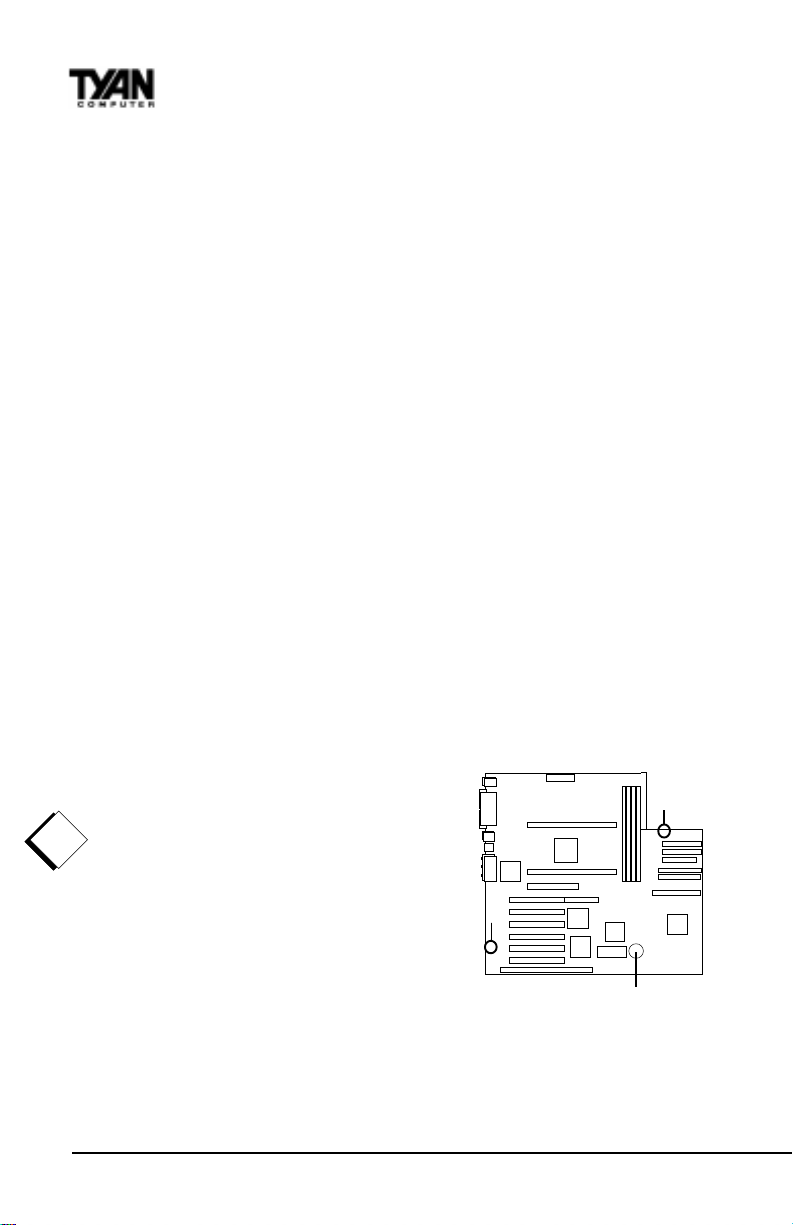
The EXTSMI (External System Management Interface) connector, JP25, is used
by some plug-in cards. Certain applications associated with these plug-in
cards use the interface for hardware control and queries.
Chassis Intrusion Alarm Connector
The J8 connector is an intrusion alarm, that can be connected to the system
chassis. When active (J8 is connected to the chassis), this alarm will alert the
system administrator anytime someone opens the system’s case.
Audio Connectors (S1836DLU only)
There are three 4-pin connectors onboard which are used for various peripherals’ audio signals. The digital signal that comes in through these connectors is
directed through the Creative Labs Vibra 16XV sound chip, and the digital
signal is turned into an audio signal which goes out through the speaker. JP18
is for modem input/output, JP19 is for Panasonic CD audio, and JP20 is for
Mitsumi CD audio.
Windows 95 Users:
You may encounter problems with some of
the devices in the Intel 82371EB chipset. Neither the PCI Bridge nor the PCI Universal Se-
rial Bus device IDs for this chipset (also
called PIIX4e) are recognized by Windows
!
95. This is a software problem, not a hard-
important!
ware problem, and can be easily remedied by
either upgrading to Windows 98 or downloading the 82371EB patch found at http://
www.tyan.com/html/drivers.html or at ftp://
download.intel.com/design/pcisets/
busmastr/setupex.exe. Note that USB requires
Windows 95 OSR 2.1 or above; please contact Microsoft for the USB update.
J8
JP17
battery
http://www.tyan.com
32
Page 33
CMOS RTC
The 440BX and 440GX AGPsets include a Real Time Clock (R TC) circuit, which
provides the date and time for the system. If the external battery for the RTC is
low , it will prevent your system from POSTing, and you will not get a display .
Normally the life span of an external battery is 2 years. If yours is running low ,
you will need to replace it with a new 3V lithium battery (Sony CR2032).
Flash EEPROM
1.
2.
3.
procedure
The Thunder 100 uses flash memory to store BIOS programs. It can be updated
as new versions of the BIOS become available. Y ou can upgrade your BIOS
easily using the flash utility (see page 88).
RAM Installation
The Thunder 100 uses a 64-bit data path from memory to CPU and can
accommodate up to 1024MB of SDRAM. The 168-pin DIMMs must be of the
3.3V, unbuffered variety . The position of the notch in the DRAM key position
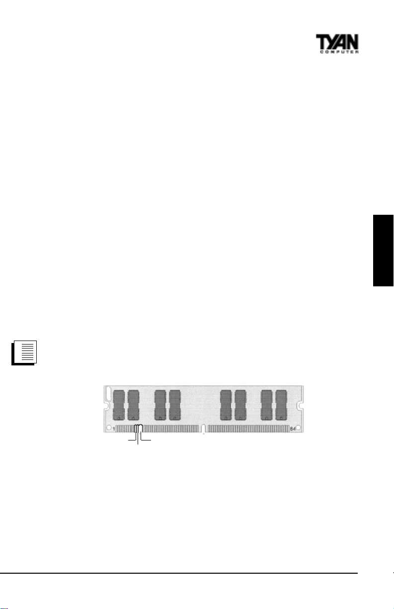
will tell you whether or not a DIMM is unbuffered (see the figure below).
100MHz SDRAM is recommended. 66MHz SDRAM can also be used only with
CPUs that use a 66MHz bus speed. All installed memory will be automatically
detected, so there is no need to set any jumpers.
Buffered
Unbuffered
168-pin DIMM
RFU
Some details of memory installation:
· One unbuffered DIMM must be installed for the system to POST.
· The mainboard supports 8MB, 16MB, 32MB, 64MB, 128MB, and 256MB
SDRAM with SPD, 100MHz or 66MHz SDRAM, and SDRAM+ECC
DIMM modules.
· The S1836DLUAN-GX also supports 512MB SDRAM with SPD modules,
although these modules are not yet validated at time of print.
ONBOARD
S1836 Thunder 100
33
Page 34

Chapter 3
Onboard Resource Settings
The table below shows some of the possible memory configurations.
1knaBMMID2knaBMMID3knaBMMID4knaBMMIDlatoT
1xBM81xBM81xBM81xBM8BM23
1xBM611xBM611xBM8
1xBM611xBM611xBM611xBM61BM46
1xBM231xBM611xBM611xBM61BM08
1xBM231xBM231xBM611xBM61BM69
1xBM461xBM231xBM611xBM61BM821
1xBM461xBM461xBM231xBM23BM291
1xBM461xBM461xBM461xBM46BM652
1xBM8211xBM461xBM461xBM46BM023
1xBM8211xBM8211xBM461xBM46BM483
1xBM8211xBM8211xBM8210BM483
1xBM8211xBM8211xBM8211xBM821BM215
1xBM652000BM652
1xBM6521xBM65200BM215
1xBM6521xBM6521xBM6520BM867
1xBM6521xBM6521xBM6521xBM652BM4201
1xBM215*1xBM215*1xBM215*1xBM215*BM8402*
0
BM04
!
important!
Warning! The 256MB DIMMs r epresented above are REGISTERED memory
chips. DO NOT use registered and non-registered memory chips simultaneously! (Check with your memory dealer for more information).
* See TY AN website for latest memory compatibility list.
Cache Memory
Penitum II processors have the L2 (Level 2) cache built into their architecture,
so there is no need for an L2 cache on the motherboard. The Pentium II
processor has a phsyical L2 cache size of 512KB and a cacheable memory area
of 512MB.
http://www.tyan.com
34
Page 35
Intel Ethernet Setup and Use
The S1836DLUAN models have the Intel 82558 10/100 Ethernet chip onboard,
which makes setting up your Ethernet connection quite simple. The following
installation and configuration instructions are courtesy of Intel, and the
copyright on the information belongs to Intel Corporation. For more information, data sheets, white papers, or demos, visit their networking web site at
http://www .intel.com/network.
You can use your modem or Internet connection to download drivers, troubleshooting tips, and more. When downloading new drivers, make sure the
archive is for the PRO/100B adapter (not PRO/100). This information can be
found on Intel’s website, as well as their FTP site and BBS service.
Connect the Network Cable.
Connect a single network cable to the PRO/100B TX PCI adapter . The cable will
1.
2.
only fit one way . For 100BASE-TX, your network cable must be category 5,
3.
procedure
twisted-pair wiring. If you plan on running the adapter at 100 Mbps, it must be
connected to a 100BASE-TX hub (not a 100BASE-T4 hub). For 10BASE-T , use
category 3, 4, or 5 twisted-pair wiring.
100BASE-TX Wiring: Twisted Pair Ethernet (TPE). Use category 5 cable and
RJ-45 connector for this adapter. Do not use category 3 wiring at 100 Mbps. At
100 Mbps, connect to a TX hub, not a T4 hub. For full duplex, see instructions
on page 13. Note: For more information on 100BASE-TX wiring requirements
and limitations, see “Fast Ethernet Wiring” in this guide and refer to the
README files on the installation disk.
ONBOARD
To configure the adapter, continue with the procedures specific to your
operating system on the pages which follow.
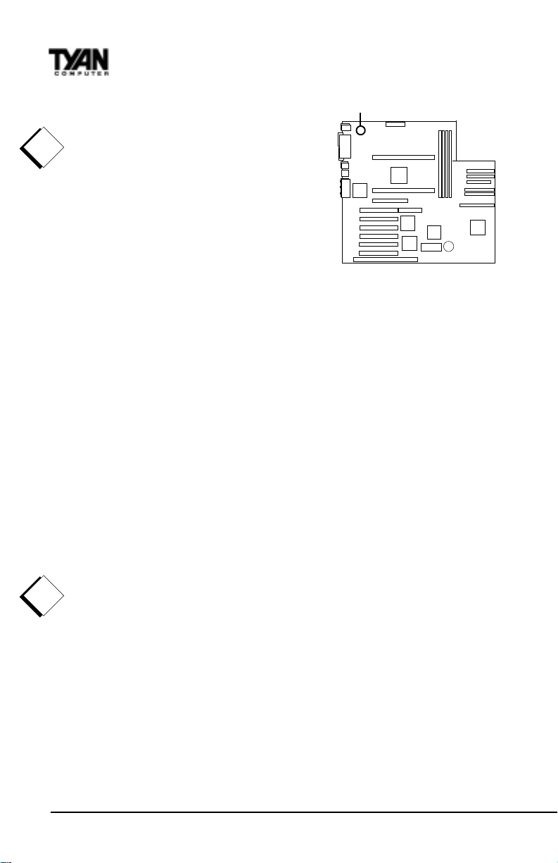
Enable the W ake-on LAN Power Jumper (JP26)
In order for the W ake On LAN (WOL) feature to work correctly , the adapter
must be connected to a continuous power source. This allows the PRO/100
adapter to “listen to” the network even when the computer is turned off. The
WOL power jumper (JP26) is enabled when the jumper is connected or closed
S1836 Thunder 100
35
Page 36
Chapter 3
Onboard Resource Settings
(ON). W arning: As always, turn of f and unplug
JP26
power to the computer before setting the WOL
jumper. The WOL connector on your mother-
!
board is live when the computer is plugged in
important!
to a power outlet. Failure to do so could
damage the adapter or computer. Also, be sure
that your ATX power supply is 2.01 compliant
or better. This level of quality is required
because WOL requires 800 mAmps of 5V
standby current.
Using Wake-on LAN
The W ake-on LAN feature operates according to a published specification. In
simple terms, the specification allows designers to build network adapters that
are capable of “listening to” network activity even when the computer is
turned off. WOL adapters have a special low power standby mode that is
active when the rest of the computer is without power. The adapter will
respond to a special “wake-up” packet sent by another computer or network
device. T ypically this wake-up packet causes the adapter to signal the computer to power up and run a pre-defined program.
The wake up packet structure and behavior is defined in the WOL specification, available from the website at http://www.us.pc.ibm.com/infobrf/iblan.html.
See the “Troubleshooting” section on page 48 for Wake-on LAN troubleshooting tips.
Configuration and Drivers
The Ethernet driver can not be installed directly from the T yan Driver CD.
Before installing the Intel 82558 Ethernet drivers, the complete LAN 82558
!
directory and all it’s contents must first be copied from the Tyan Driver CD
important!
onto your hard drive. The 82558 driver can then be installed from your hard
drive.
Make sure that you are following the proper instructions for your operating
system (e.g. if you are using Windows 95, do not follow the W indows NT
instructions).
36
http://www.tyan.com
Page 37
DOS and Windows 3.1 Setup for Novell NetW ar e Clients
Automatic configuration
PCI computers automatically detect and configure PCI-compliant adapters
while booting. The Intel 82558-based Integrated Fast Ethernet For WfM
adapter IRQ level and I/O memory address are automatically set by the BIOS
each time you start your computer.
Start your computer to automatically configure the adapter. Configuration is
complete when the DOS prompt appears. You can now continue with the
procedure below .
Run Setup to install network drivers
Setup can automatically install NetW are DOS ODI client drivers for you or
display a README file with installation instructions for other NOS drivers.
1. If your computer already has network drivers installed, restart the computer
1.
2.
without loading them. If the drivers are loaded from the AUTOEXEC.BAT or
3.
procedure
CONFIG.SYS file, type REM in front of each line that loads a network driver. Or ,
with DOS 6.x or later press 5 as DOS starts, to bypass the drivers.
2. Insert the Intel Configuration and Drivers floppy/CD in a drive, switch to the
appropriate drive/directory , and at the DOS prompt, type SETUP.
3. If you have more than one Intel PRO series PCI adapter in your computer, an
adapter selection menu appears on the screen. Select the adapter you want by
noting the Ethernet address. See “Installing Multiple Adapters” for more
information.
4. Select Automatic Setup from the Main menu. Then follow the instructions
on the screen. (If you want to test the adapter with a responder on the
network, see the next procedure.) Setup displays the adapter’s configuration,
then runs a series of diagnostic tests that makes sure the adapter and network
are functioning properly . If Setup finds a problem, it displays the results and
some possible solutions.
5. When Setup finishes the tests, you’ll see the Install Network Drivers screen.
6. Select the driver you want to install. Setup can install a NetW are client driver
for you. If you’re installing other drivers, Setup displays a README file with
installation instructions. If you can’t connect to a server, first try the suggestions here, then turn to the “Troubleshooting” section on page 48.
ONBOARD
• Make sure you’re using the drivers for this adapter. The driver filename
contains the letter B (for example, E100BODI.COM).
S1836 Thunder 100
37
Page 38

Chapter 3
Onboard Resource Settings
• If you’re replacing an existing adapter, make sure the LINK statement in your
NET .CFG is correct for the new adapter . For example, the LINK statement for a
NetW are client should be:
LINK DRIVER E100BODI
• V erify that the frame type in your NET .CFG file matches your network.
• If setting up a server, check your LOAD and BIND statements.
• Test the adapter by running diagnostics in Setup. Additional testing is
available by using a responder (see below).
• Check the README files.
Responder testing on the network (optional)
Setup can test the adapter more thoroughly if you have a responder on the
network while running the tests.
1.
1. Go to a computer on the network with any EtherExpress adapter installed
2.
(except EtherExpress 32 or EtherExpress 16 MCA).
3.
procedure
2. Run the appropriate configuration program for the installed adapter and set
it up as a responder.
3. Return to the computer with the new adapter. Run Setup and make the new
adapter a sender. Test the adapter.
Windows NT Server or W orkstation
Automatic configuration
PCI computers automatically detect and configure PCI-compliant adapters
while booting. The Intel 82558-based Integrated Fast Ethernet For WfM
adapter IRQ level and I/O address are automatically set by the BIOS each time
you start your computer. Start your computer to automatically configure the
adapter. Configuration is complete when W indows NT starts or the DOS
prompt appears.
Install network drivers - Windows NT Version 4.0 only
W e recommend that you install the network drivers for the onboard Intel 82558
network adapter after NT has been installed. In other words, do not let NT
auto-detect the onboard network card during the installation. The following
steps will guide you through the installation procedure. You will need to have
the T yan driver CD and the NT 4.0 CD for this procedure.
1. Boot NT 4.0
2. Get the Tyan Driver CD and copy the Intel LAN drivers to a directory on
http://www.tyan.com
38
Page 39
1.
your hard disk drive.
2.
3. Double-click the Network icon in the Control Panel
3.
procedure
4. Click the Adapters tab in the window that appears.
5. Click Add. A list of adapters appears.
6. Select the “Have Disk” icon and point it to the directory that you created on
your hard drive in step 2.
7. Y ou will see “Intel Ether Express PRO PCI Adapter”. Click OK.
8. Follow the NT prompts to complete the installation. (This will require the NT
4.0 CD)
9. Click OK in the main PROSet window to return to Windows NT .
10. The Intel adapter now appears as the “Intel 82558-based 10/100 Ethernet
Adapter” on the list in the Network window . Click Close to finish.
11. Restart W indows NT when prompted.
T o install multiple adapters, repeat this procedure for each new adapter. See
“Installing Multiple Adapters” for specific information. T o run the PROSet
software at any time, double-click the Intel PROSet icon in the Control Panel or
click the Adapter Properties button.
Install network drivers - Windows NT Version 3.5x only.
After putting the adapter in the computer and starting Windows NT, you need
to install the Intel drivers and test the adapter.
1. Double-click the Network icon in the Control Panel.
1.
2. Click Add Adapter.
2.
3. When the list of adapters appears, scroll to the end of the list and select
3.
procedure
<Other> Requires disk from manufacturer.
4. Insert the Intel Configuration and Drivers disk/CD in the drive and click OK.
Drivers and the Intel PROSet utility are installed and PROSet starts. PROSet is
an enhanced utility that you can use to easily configure and test your adapter
in Windows NT. PROSet also displays the computer resources that were
assigned to each PRO adapter installed. The PROSet main window is shown
on the preceding page.
5. Click OK in the PROSet main window to return to Windows NT .
6. Click OK in the Network Settings dialog box and remove the installation
disk. When prompted, restart Windows NT.
ONBOARD
T o install multiple adapters, repeat this procedure for each new adapter. See
“Installing Multiple Adapters” for specific information. T o run the PROSet
software at any time, double-click the Intel PROSet icon in the Control Panel.
S1836 Thunder 100
39
Page 40

Chapter 3
Onboard Resource Settings
If Windows NT reports an error or you can’t connect to the network, try the
suggestions here first, then turn to the “Troubleshooting” section on page 48
if necessary.
• Make sure you’re using the drivers for this adapter. Drivers are located on the
Windows NT CD-ROM or on the Intel Drivers and Configuration disk version
2.3 or later.
• Make sure the driver is loaded and the protocols are bound. Check the
Network Bindings dialog box in Windows NT .
• Check the Windows NT Event V iewer for error messages.
• If you are attaching to a NetW are network, check your frame type and verify
that NetWare client software has been installed.
• Test the adapter with PROSet. After installing the adapter you can run
PROSet from your hard disk. T o do this, double-click the Intel PROSet icon in
the Control Panel. Click T est to run diagnostics. For additional information,
click Help in the PROSet window.
• Check with your LAN administrator — you may need to install supplemental
networking software.
Windows 95
Automatic Configuration
PCI computers automatically detect and configure PCI-compliant adapters
while booting. The Intel 82558-based Integrated Fast Ethernet For WfM
adapter IRQ level and I/O address are automatically set by the BIOS each time
you start your computer. Start your computer to automatically configure the
adapter. Configuration is complete when W indows 95 starts.
Install Network Drivers from Diskette
Have your Windows 95 installation CD-ROM or disks available, as W indows
95 prompts for them when you install the new adapter.
1.
1. After you put the adapter in the computer, start W indows 95. The New
2.
Hardware Found dialog box appears. If this box does not appear and Windows
3.
procedure
95 starts normally, you may need to manually add the adapter. See the troubleshooting section at the end of this Windows 95 section..
2. Click “Driver from disk provided by hardware manufacturer,” then click OK.
The Install From Disk dialog box appears.
3. Insert the Intel Configuration and Drivers disk/CD.
4. Specify the path, then click OK.
40
http://www.tyan.com
Page 41
5. Follow prompts for any Windows 95 installation disks and restart when
prompted. (If you installed from CD-ROM, the installation files are typically
located at D:\Win95, where D is your CD-ROM drive.)
After restarting Windows 95, you should be able to connect to your network
by double-clicking the Network Neighborhood.
Install PROSet Software
PROSet is an enhanced Intel utility that you can use to easily configure and
test your adapter in Windows 95. PROSet also displays the computer resources that were assigned to each PRO adapter installed. T o install PROSet:
1. Insert the Intel Configuration and Drivers CD.
1.
2.
2. From My Computer or the Windows Explorer , double-click the CD icon.
3.
procedure
3. Click the “Proset” icon or filename and click the right mouse button. From
the menu that appears, click Install.
4. The PROSet files are copied to your hard disk.
5. Start PROSet by double-clicking on the Intel PROSet icon in the Control
Panel.
6. The PROSet software examines your computer and displays an Intel PROSet
window.
7. Click OK to exit PROSet and return to Windows 95.
Manually Adding an Adapter
If the New Hardware Found dialog box does not appear at startup and you
cannot connect to the network, check the Device Manager list to see if the
new adapter is present. If it is not, use the following procedure.
1.
1. From the Control Panel, double click the System icon.
2.
2. Click the Device Manager tab in the window that appears.
3.
procedure
3. Double-click Other Devices (question mark icon) in the list area.
4. Double-click PCI Ethernet Controller.
5. Click the Driver tab, then click Change Driver.
6. Select Network Adapters and click OK.
7. Click Have Disk from the window that appears. Insert the Intel Configuration
and Drivers Disk and click OK.
8. Follow any prompts for Windows 95 installation disks and restart when
prompted.
ONBOARD
If you can’t connect to a server or if Windows 95 reports an error after you
S1836 Thunder 100
41
Page 42

Chapter 3
Onboard Resource Settings
double-click Network Neighborhood, try the suggestions here first, then turn
to the “Troubleshooting” section if necessary.
• Make sure you’re using the drivers that are on the drivers diskette that ships
with this adapter.
• Make sure the driver is loaded and the protocols are bound. Check Device
Properties list for trouble indicators (an X or ! symbol).
• T est the adapter. Start PROSet (see page 43) and click T est to run diagnostics.
• Check with your LAN administrator — you may need to install supplemental
networking software.
Windows 98
Windows 98 will automatically configure and install the drivers for the Ethernet
chip upon fresh installation.
NetWar e Server , Client 32, UNIX, OS/2, Banyan, and
Other Operating Systems
For these, refer to our online documents. On a DOS computer, view the
appropriate README file for information on installing your network driver. T o
view the README files, insert the Intel Configuration and Drivers disk into a
drive, switch to that drive, and type: SETUP /README. Look through the
selection called “Installing EtherExpress PRO/100B TX PCI Adapter Drivers”
for the operating system you need.
Installing Multiple Adapters
All users: The adapter’s 12-digit, hexadecimal Ethernet address is on a sticker
on the motherboard near the LAN controller chip. The Ethernet address is
sometimes called the node address or the MAC address. Note that the PCI slot
number may not correspond with the physical connector in your computer.
Install only one active WOL adapter per computer. You can install additional,
non-WOL adapters.
NetW are users: The server drivers use the PCI slot number to identify each
installed adapter. You can correlate the PCI slot number to the adapter by using
the Ethernet address that is printed on a label on the adapter. Run Setup from
the Intel disk to view the Ethernet address and slot number for each installed
http://www.tyan.com
42
Page 43

adapter. For more information, see the README files. NetWare 4.11 server
installations use unique slot numbers that are assigned during sever setup.
Windows NT and Windows 95 users: Repeat the configuration procedure for
each adapter you want to install (add only one adapter at a time). While
PROSet can detect all the PRO/100B adapters in your computer, you still need
to perform the configuration process on each adapter. In Windows NT , be sure
to click the Show all PRO Adapters box in the Configuration window . See the
README file for more information.
Select Duplex Mode (optional)
Duplexing is a performance option that lets you choose how the adapter sends
and receives data packets over the network. The PRO/100B TX adapter can
operate at full duplex only when connected to a full duplex 10BASE-T ,
100BASE-TX switching hub, or another full duplex adapter. T o summarize:
• Auto (requires a full duplex adapter or switching hub with auto-negotiation
capability). The adapter negotiates with the hub to send and receive packets at
the highest rate. This is the default setting. If the hub does not provide autonegotiation, the adapter runs at half duplex.
• Full duplex (requires a full duplex switching hub or adapter). The adapter can
send and receive packets at the same time. This mode can increase adapter
performance capability . If the full duplex hub provides auto-negotiation, the
adapter runs at full duplex. If the full duplex hub does not provide autonegotiation, you need to set the adapter duplex mode manually (see following
paragraphs)
• Half duplex. The adapter performs one operation at a time; it either sends or
receives.
ONBOARD
Note: If your hub is running at 100 Mbps and half duplex, your potential
bandwidth is higher than if you run at 10 Mbps and full duplex.
Manually Configuring for Full Duplex
If your switch supports auto-negotiation with the N-way standard, duplex
configuration is automatic and no action is required on your part. However,
few switches in the current installed base support auto-negotiation. Check
with your network system administrator to verify . Most installations will
require manual configuration to change to full duplex.
S1836 Thunder 100
43
Page 44
Chapter 3
Onboard Resource Settings
Configuration is specific to the driver you’re loading for your network operating system (NOS), as shown in the following paragraphs.
To set up the duplex mode, refer to the section below that corresponds to your
operating system. Adapter performance may suffer or your adapter may not
operate if your hub does not support full duplex and you configure the adapter
to full duplex. Leave the adapter on half duplex if you are not sure what type of
hub you are connected to.
DOS ODI, NDIS 2.01 Clients
Edit the NET .CFG or PROTOCOL.INI file. Add kewords to Link Driver section:
FORCEDUPLEX 2
SPEED 100 (or 10 if 10BASE-T)
NetWare Server
In AUTOEXEC.NCF , Load E100B.LAN and add the following statement (you
must include the equal sign for servers):
FORCEDUPLEX=2
SPEED=100 (or 10 if 10BASE-T)
For more information, see the README file for NetW are servers.
Windows NT
While running Windows NT :
1.
1. From the Control Panel, double-click the Intel PROSet icon.
2.
2. PROSet examines your system and displays the Adapter Setup window . If
3.
procedure
you have multiple adapters, click the “Show All Adapters” box and then select
the adapter you are configuring (you can identify it by its Ethernet address).
Each adapter must be configured separately . See “Installing Multiple Adapters” for more information.
3. From the window that appears, click Change.
4. From the Adapter Setup window , click the menu for Network Speed.
5. Click 100 or 10 Mbps, depending on hub speed.
6. Click the menu for Duplex Mode
7. Click Full.
8. Click OK when finished.
9. Click Restart Windows NT .
44
http://www.tyan.com
Page 45

Windows 95
While running Windows 95:
1.
1. From the Control Panel, double-click the Intel PROSet icon.
2.
3.
2. PROSet examines your system and displays the Adapter Setup window . If
procedure
you have multiple adapters, click the adapter you are configuring (you can
identify it by its Ethernet address). Each adapter must be configured separately . See “Installing Multiple Adapters,” for more information.
3. From the window that appears, click Change.
4. From the Adapter Setup window , click the menu for Network Speed.
5. Click 100 or 10 Mbps, depending on hub speed.
6. Click the menu for Duplex Mode
7. Click Full.
8. Click OK when finished.
9. Click OK to restart Windows 95.
Other operating systems
See the Adapter Installation and Special Configurations README file.
“Push” Installation for Windows 95
If you are a LAN Administrator setting up server-based push installation of
Windows 95 as defined in Microsoft W indows 95 Resource Kit, additional
steps are required for this adapter. Refer to the Push Installation for Windows
95 README file under the Microsoft section of Installing EtherExpress PRO/
100B adapter drivers.
ONBOARD
T roubleshooting
If the adapter can’t connect to the network:
· Make sure the cable is installed properly . The network cable must be
securely attached at both RJ-45 connections (adapter and hub). If the
cable is attached but the problem persists, try a different cable. The
maximum allowable distance from adapter to hub is 100 meters. If you’re
directly connecting two computers (no hub), use a crossover cable. Most
hubs require a straight-through cable, while most switches require a
crossover cable (see your hub or switch documentation to verify). See the
Cabling Information README file for more information on cross-over
cables.
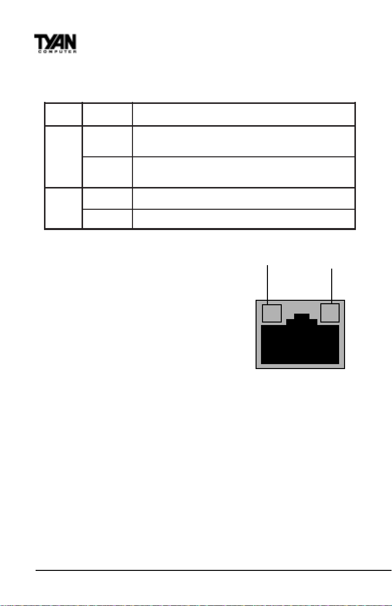
· Check the LED lights on the adapter. The on-board cable connector has
two diagnostic LEDs. These lights help indicate if there’s a problem with
S1836 Thunder 100
45
Page 46
Chapter 3
Onboard Resource Settings
the connector, cable, or hub. The table below describes the LEDs, and the
drawing on the next page shows their location.
DELnoitacidnIgninaeM
KNL nO
)wolley( ffO
001 nO.spbM001tagnitareponoitcennockrowteN
)neerg( ffO.spbM01tagnitareponoitcennockrowteN
· Make sure you’re using the correct
100 Mbps LED
.doogsiretpadadnabuhehtneewtebknileht
.melborpnoitarugifnocrevirdaevahuoyro
Link LED
drivers. Make sure you’re using the
drivers that come with this adapter. The
driver filename contains the letter B (for
example, E100BODI.DOS). Drivers that
support previous versions of the
Y
EtherExpress PRO/100 PCI adapter do
not support this version of the adapter.
· Make sure the hub port and the adapter
have the same duplex setting. If you configured the adapter for full duplex,
make sure the hub port is also configured for full duplex. Setting the
wrong duplex mode can degrade performance, cause data loss, or result in
lost connections.
;noitcennocadegdelwonkcaevahbuhdnaretpadaehT
,ytluafsiretpadadnabuhehtneewtebnoitcennocelbacehT
G
Testing the adapter
T est the adapter by running Intel diagnostics. For DOS or Windows 3.1
computers, run Setup on the Intel Drivers and Configuration disk. For Windows NT and Windows 95 run Intel PROSet by double-clicking the Intel
PROSet Icon in the Control Panel. Click Help from the main PROSet window to
get complete diagnostics information and instructions.
http://www.tyan.com
46
Page 47

Common problems and solutions
SETUP.EXE reports the adapter is “Not enabled by BIOS”.
• The PCI BIOS isn’t configuring the adapter correctly .
The computer hangs when the drivers are loaded.
• Change the PCI BIOS interrupt settings.
• If you are using EMM386, it must be version 4.49 or newer (this version ships
with MS-DOS 6.22 or newer).
Diagnostics pass, but the connection fails or errors occur.
• At 100 Mbps use category 5 wiring and make sure the network cable is
securely attached.
• For NetW are clients, make sure you specify the correct frame type in our
NET .CFG file.
• Make sure the duplex mode setting on the adapter matches the setting on the
hub.
• At 100 Mbps, connect to a 100BASE-TX hub only (not T4).
The LNK LED doesn’t light.
• Make sure you’ve loaded the network drivers.
• Check all connections at the adapter and the hub.
• Try another port on the hub.
• Make sure the duplex mode setting on the adapter matches the setting on the
hub.
• Make sure you have the correct type of cable between the adapter and the
hub. 100 BASE-TX requires two pairs. Some hubs require a crossover cable
while others require a straight-through cable. See the Cabling README file for
more information on cabling.
ONBOARD
The adapter stopped working when another adapter was added to the
computer.
• Make sure the cable is connected to the EtherExpress PRO/100 TX PCI
adapter.
• Make sure your PCI BIOS is current.
• Make sure the other adapter supports shared interrupts. Also, make sure
your operating system supports shared interrupts — OS/2 doesn’t.
• Try reseating the newest adapter.
The adapter stopped working without apparent cause.
• Try reseating the adapter first, then try a different slot if necessary.
• The network driver files may be corrupt or deleted. Delete and then reinstall
S1836 Thunder 100
47
Page 48

Chapter 3
Onboard Resource Settings
the drivers.
• Try a different PRO/100 TX PCI adapter .
• Run the diagnostics.
The Wake-on LAN feature is not working.
• Make sure the WOL cable is attached and power is applied to the computer.
• Check the BIOS for its WOL setting. Some computers may need to be
configured to WOL.
• Make sure the network cable is fully attached to the adapter.
Link LED does not light when power is connected.
• Make sure WOL cable is attached and power is applied to computer.
• Make sure network cable is attached at both ends.
T echnical Information
Fast Ethernet Wiring
100BASE-TX Specification: The 100BASE-TX specification supports
100 Mbps transmission over two pairs of category 5 twisted-pair
Ethernet (TPE) wiring. One pair is for transmit operations and the
other for receive operations. Segment lengths are limited to 100 meters
with 100BASE-TX for signal timing reasons. This complies with the
EIA 568 wiring standard.
Fast Ethernet Hub and Switches
The two basic types of hubs are shared hubs and switching hubs.
Ether-Express PRO/100 TX adapters can be used with either type of
hub for 10 Mbps. At 100 Mbps, a TX hub or switch is required.
Shared hubs
In a shared network environment, computers are connected to hubs
called repeaters. All ports of the repeater hub share a fixed amount of
bandwidth, or data capacity . On a 100 Mbps shared hub, all nodes on
the hub must share the 100 Mbps of bandwidth. As stations are added
to the hub, the effective band-width available to any individual station
gets smaller. Shared hubs do not support full duplex.
Think of a shared repeater hub as a single-lane highway that everyone
http://www.tyan.com
48
Page 49

shares. As the number of vehicles on the highway increases, the traffic
becomes congested and transit time increases for individual cars.
On a shared hub all nodes must operate at the same speed, either 10
Mbps or 100 Mbps. Fast Ethernet repeaters provide 100 Mbps of
available bandwidth, ten times more than what’s available with a
10BASE-T repeater.
Repeaters use a well-established, uncomplicated design, making them
highly cost effective for connecting PCs within a workgroup. These are
the most common type of Ethernet hubs in the installed base.
Switching hubs
In a switched network environment, each port gets a fixed, dedicated
amount of bandwidth. In the highway scenario, each car has its own
lane on a multi-lane highway and there is no sharing.
In a switched environment, data is sent only to the port that leads to the
proper destination station. Network bandwidth is not shared among all
stations, and each new station added to the hub gets access to the full
bandwidth of the network.
If a new user is added to a 100 Mbps switching hub, the new station
receives its own dedicated 100 Mbps link and doesn’t impact the 100
Mbps bandwidth of another station. Switching hubs can effectively
increase the overall bandwidth available on the network, significantly
improving performance. Switching hubs can also support full duplex.
ONBOARD
For more information on Fast Ethernet, visit the Network Products
website (http:// www .intel.com/network).
Creative Labs Sound Drivers Installation Note
For 1836DLUAN-GX Win NT 4.0
Creative Labs V ibra16 Setup
Note: This note assumes drive D: for your CDROM drive.
1.
1) Install NT 4.0 and Service Pack 3 onto your hard drive.
2.
3.
2) Login as Administrator
procedure
S1836 Thunder 100
49
Page 50

Chapter 3
Onboard Resource Settings
3) Rename C:\WINNT\INF\W A VE.INF
C:\WINNT\INF\W AVE.OLD
4) Go to D:\DR VLIB\PNPISA\X86 on your WinNT CDROM
5) Right Click on PNPISA.INF .. Select “Install”. This will start the
Plug and play driver installation.
6) Restart the system when prompted. Login as Administrator.
a)After logging in, you will get a “New Hardware Found” dialog box:
“Creative ViBRA16X PnP (Audio)”
“Select which driver you want to install for your new hardware”
(Driver from disk provided by hardware manufacturer)
b) Insert the T yan Computer CDROM into he CDROM drive.
W ait 5-10 seconds, then Click on OK.
7) The “Install from disk” dialog box appears.
a) T ype in the drive letter of your CDROM drive (Ex. D:\), then
Click on “Browse”.
b) Double Click “Audio”
c) Double Click “S1836”
d) Double Click “WINNT 40”
e) Click “Open” D:\Audio Driver\S1836\WinNT 40 will be
displayed.
f) Click “OK” .
8) The “Select Device” screen shows “Creative Sound Blaster 16 Plug
and Play”
a) Click “OK” files are copied
9) Then the “Sound Blaster 16 Configuration” screen shows the
resource allocation for the Sound Blaster feature. If there are
“conflicts” listed in the “Conflicting device list”,adjust the “Resource
settings”. If no conflicts, Click “OK”.
10) An “Insert Disk” Dialog Box appears. Follow the instructions then
Click “OK”
11) A “New Hardware Found” Message will appear . “Microsoft
Joystick Port Enabler”
a) Then a “Files Needed” Dialog Box will appear. In the “Copy
files from:” box, type in: D:\DRVLIB\AUDIO\SBPNP\I386
(D: drive file path refers to Windows NT 4.0 CD)
Then Click “OK”
b) The “Joystick Port Configuration” Dialog Box appears. If no
conflicts, Click “OK”
12) Y ou will then be asked to restart your computer . Select “Yes”.
System will reboot and sound will play after logging in.
50
http://www.tyan.com
Page 51
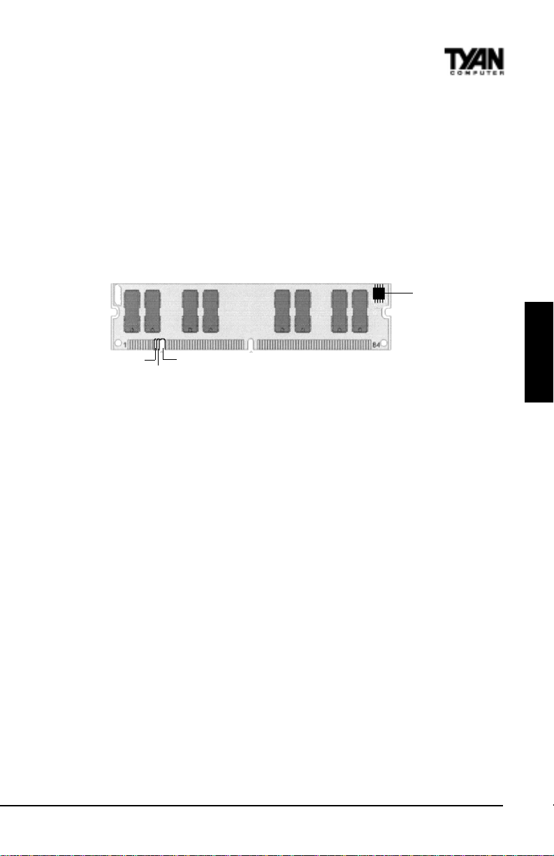
Frequently Asked Questions
Q: Why don’t I get a display after I put in my old DIMM module?
A: The 440BX/GX chipset requires the memory manufacturer to program an
EEPROM chip with SPD (Serial Presence Detection) on the module in order for
the BIOS to program the chipset’s timing registers properly . Your DIMM may
not have the EEPROM chip on the module, or the EEPROM may not contain
the correct program. Check with your memory vendor for details. The figure
below shows a DIMM module with an SPD EEPROM chip.
EEPROM
RFU
Unbuffered
Buffered
168-pin DIMM
Q: My system sometimes becomes unstable. How should I check the system?
A: The first thing to do is to check and see if you have any device conflict in I/
O address, IRQ, or DMA. If you are using Windows 95, the Device Manager is
a good place to start. Please consult your operating system manual for details.
Second of all, slowing down the memory timing in the BIOS’s chipset setup
section will help the situation, as well. Many memory modules are not suitable
for high performance systems and are probably the main source of your
problem.
Q: Can I use EDO DIMMs on this motherboard?
A: No. The Intel 440BX/GX AGPset does not support EDO memory .
Q: What is AGP?
A: AGP (Accelerated Graphics Port) is a new bus architecture for 3D graphics.
The AGP slot eliminates the PCI bandwidth bottleneck by bypassing the PCI
interface and accessing the system memory directly . Currently , the AGP
supports 1X and 2X modes, which yield bandwidths of 266MB/s (at 33MHz
bus speed) and 533MB/s (at 66MHz bus speed), respectively . Compare this
with the mere 132MB/s (at 33MHz bus speed) that you get from the PCI bus.
ONBOARD
Q: Does my operating system support AGP?
A: Currently , only Windows 98 and W indows 2000 will have built-in support
for AGP . Some AGP cards require W indows 95 OSR2.1 or a special driver from
S1836 Thunder 100
51
Page 52

Chapter 3
Onboard Resource Settings
Intel. Please check with your graphics vendor for more details.
Q: How do I install the on-board NIC drivers for W inNT 4.0?
A: The Ethernet driver can not be installed directly from the T yan Driver CD.
Before installing the Intel 82558 Ethernet drivers, the complete 82558 directory
and ALL its components must first be copied from the T yan CD onto your hard
drive. The 82558 installation program can then be copied normally from your
hard drive.
Q: How do I use / enable the RAIDport on the motherboard?
A: All S1836Ds will support the RAIDport as long as the RAIDport card has
BIOS version 3.1 or above. Y ou must also us the ARO-1 130CA driver set
version 3.1. The ARO-1130A is now supported also. It is recommended that
you purchase your RAIDport card from one of Tyan's distributors. Tyan
motherboards have been qualified to use ARO-1130CA or ARO-1 130SA for
best results.
Q: I get a memory test failure or sequencer error when I install the RAIDport
card into the S1836 even though the memory is good.
A: The RAIDport BIOS will report a memory or sequencer failure on the S1836
if you are using RAIDport BIOS version 3.0. Y ou MUST use RAIDport BIOS
version 3.1 for it to work on the S1836.
Q: What RAID levels are supported on the S1836 and RAIDport II card?
A: Currently , RAID levels 0 and 1 are supported on the ARO-1130CA and
RAID 0,1,0/1, and 5 are supported when using the ARO-1130SA.
Q: How can I disable the keyboard detection in the BIOS v .1.12?
A: Y ou need to enable the Quick Boot option in CMOS - then the BIOS will not
check for a keyboard.
Q: I cannot install Windows NT when I use an LS/120-type floppy disk drive.
What should I do?
A: SYMPTOM - When you are trying to install Windows NT , you may
experience any of the following symptoms:
1) When you boot from the installation disks, the following error message
may be displayed when disk 2 is inserted:
http://www.tyan.com
52
Page 53

Stop 0x0000007B Inaccessible Boot Device
(0xFF109C50, 0x00000000, 0x00000000, 0x00000000)
2) When you are attempting to create a set of installation disks using the
WINNT /ox or WINNT32 /ox command, the following error message may be
displayed:
This floppy disk is not formatted as high-density, not formatted
with a standard Windows NT or MS-DOS format, or is corrupted.
Setup is unable to use this disk.
CAUSE OF THE PROBLEM: Y ou are using a LS/120-type floppy disk drive.
RESOLUTION - To work around this issue, install W indows NT W orksta
tion with the /b switch. This causes Windows NT Workstation Setup to run
without requiring the installation disks.
If you are using the S1836D or are installing with Adaptec 3940 with AIC7895 chip then you must install NT 4.0 with a standard 1.44MB floppy disk.
Q: Where can I get Intel PRO/100 + LAN Adapter drivers?
A: You may download the drivers at http://support.intel.com/support/network/
adapter/100PDISK.HTM.
ONBOARD
S1836 Thunder 100
53
Page 54

Chapter 4
BIOS Configuration
This page is intentionally left blank.
54
http://www.tyan.com
Page 55
chapter 4
BIOS Configuration
The AMIBIOS Setup screen is shown below .
AMI BIOS EASY SETUP UTILITY Ver.1.16
(c)1998 American Megatrends, Inc. All Rights Reserved
Main Advanced Security Exit
System Date Thu Oct 15 1998 Setup Help
System Time 12:55:37
Floppy Drive A 1.44 MB 3½ Day: 01 - 31
Floppy Drive B Not Installed Year: 1901 - 2099
Primary IDE Master Auto
Primary IDE Slave Auto
Secondary IDE Master Auto
Secondary IDE Slave Auto
Auto-Detect Hard Disks [ Enter ]
Boot Sector Virus Protection Disabled
ESC:Exit Enter:Select F5:Setup Defaults F6:Original Values F10:Save & Exit
S1836 Thunder 100
55
Month: Jan - Dec
- Previous Item
¯ Next Item
Select Menu
®¬
BIOS
Page 56
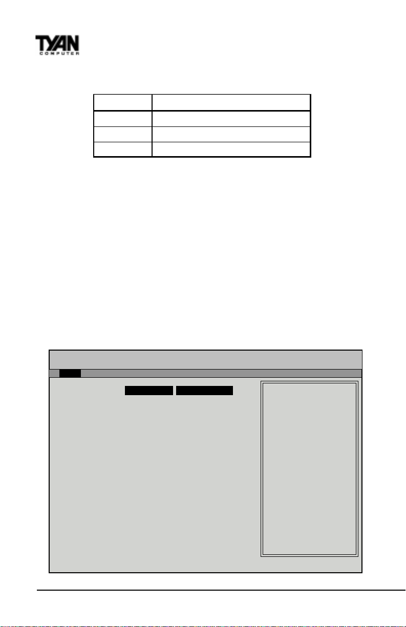
Chapter 4
BIOS Configuration
You can select a Setup option by using the following keyboard keys:
Key Function
Tab Moves f rom one box to the next
Arrow keys Changes selections within a box
Enter O pe n s highli ght ed sele cti on
The pages which follow contain explanations of the settings for the AMIBIOS
Setup menus. Drawings have been included for ease of reference. Overall, the
AMIBIOS Setup program is easy to use, and fairly intuitive. Note that the
graphics in the manual are simpler than those that appear on your screen.
Main Setup
Select the AMIBIOS Setup options below by choosing Main Setup from the
AMIBIOS Setup main menu. The Standard Setup menu screen is shown below .
AMI BIOS EASY SETUP UTILITY Ver.1.16
(c)1998 American Megatrends, Inc. All Rights Reserved
Main Advanced Security Exit
System Date Fri Jan 1 1999 Setup Help
System Time 12:55:37
Floppy Drive A 1.44 MB 3½ Day: 01 - 31
Floppy Drive B No t I n stalled Year: 1901 - 2099
Primary IDE Master Auto
Primary IDE Slave Auto
Secondary IDE Master Auto
Secondary IDE Slave Auto
Auto-Detect Hard Disks [ Enter ]
Boot Sector Virus Protection Disabled
ESC:Exit Enter:Select F5:Setup Defaults F6:Original Values F10:Save & Exit
56
Month: Jan - Dec
- Previous Item
¯ Next Item
Select Menu
®¬
http://www.tyan.com
Page 57
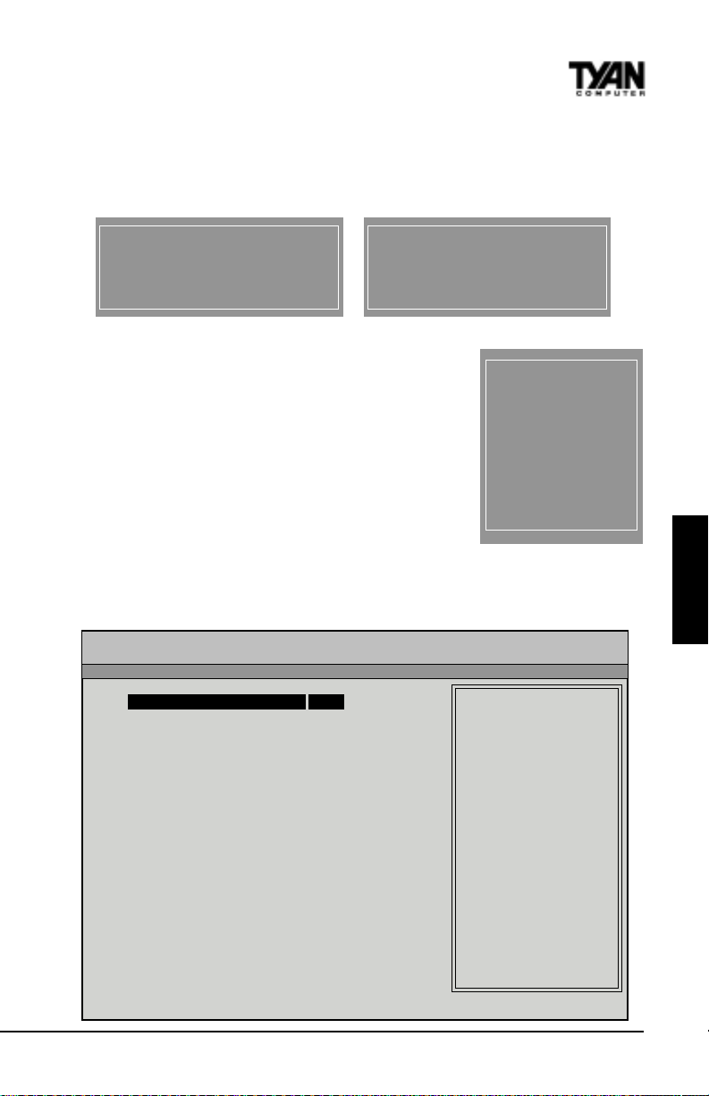
System Date/Time
You can type the date and time in directly, or select the portion of the date or
time that you want to modify and adjust it using the - ¯ cursor keys. The clock
runs on a 24-hour cycle (i.e. 1:00 PM is 13:00).
[ System Date Setting ]
MM/DD/YY: Jan 1 1998
[ System Time Setting ]
Current Time 12:00:00
Floppy Drive A: and B:
Move the cursor to these fields via the arrow keys and
OPTIONS
select the floppy type. The settings are 360KB 5¼
inch, 1.2 MB 5¼ inch, 720KB 3½ inch, 1.44MB 3½
inch, or 2.88MB 3½ inch. If you are not sure what type
of floppy drive you have, consult the documentation
that came with your drive.
Not Installed
360 KB 5¼
1.2 MB 5¼
720 KB 3½
1.44MB 3½
2.88MB 3½
Primary Master , Primary Slave, Secondary Master , Secondary Slave
Select these options to configure the various drives. A screen with a list of
drive parameters appears.
AMI BIOS EASY SETUP UTILITY Ver.1.16
(c)1998 American Megatrends, Inc. All Rights Reserved
Main
IDE Device Configuration AUTO Setup Help
Cylinders USER: Set Parameters
Heads by User
Write Precompensation AUTO: Set Parameters
Sectors automatically
Maximum Capacity CD-ROM: Use for ATAPI
LBA Mode O R
Block Mode Double click [AUTO] to
Fast Programmed I/O Modes set all HDD parameters
32 Bit Transfer Mode ON automatically
1-46: Predefined types
CD-ROM drives
BIOS
ESC:Back Enter:Select
S1836 Thunder 100
-¯:Select Items F5:Setup Defaults F6:Original Values
57
Page 58

Chapter 4
BIOS Configuration
IDE Device Configuration: T o have the BIOS autodetect the IDE drive, select
Auto. Otherwise, you may choose one of the 46 drive types offered, or enter
the parameters yourself (see Entering Drive Parameters on page 3-5). Consult
the table below to see how to configure various drive types yourself.
epyTerugifnoCotwoH
ISCS
EDI
MOR-DC
MFMdradnatS
MFMdradnatS-noN
tceleS epyT tceleS. dellatsnItoN ehT.neercsretemarapevirdehtno
otuoywolladluohsrerutcafunamISCSehtybdedivorpsrevirdISCS
.evirdISCSehterugifnoc
tceleS epyT tceleS. otuA .sretemarapehtenimretedSOIBIMAtelot
nokcilC KO tceleS.sretemarapevirdehtsyalpsidSOIBIMAnehw
edoMABL tceleS. nO nahtretaergyticapacasahevirdehtfi
.BM045
tceleS edoMkcolB tceleS. nO .srefsnartatadedomkcolbwollaot
tceleS edoMtiB-23 tceleS. nO tceleS.srefsnartatadtib-23wollaot
eht edoMOIP tcelesottsebsitI. otuA otSOIBIMAwollaot
tonsitahtedomOIPatcelesuoyfI.edomOIPehtenimreted
uoyfI.ylreporpkrowtonlliwevirdeht,evirdEDIehtybdetroppus
OIPtceles,edomOIPs'evirdehtwonkuoytahtniatrecyletulosbaera
.etairporppasa,4-0edom
tceleS epyT tceleS. MORDC nokcilC. KO syalpsidSOIBIMAnehw
.sretemarapevirdeht
tahtemehcsgnidocnenaesuhcihwsrevirdredloerasevirdMFM(
tceleS).mooregarotssseldnasseccaatadrewolssecudorp epyT .
tahtepytevirdehttceleS.sretemarapevirdehtwonktsumuoY
.sretemaraps'evirdruoysehctamyltcaxe
tceleS epyT evirdehthctamtonodsretemarapevirdehtfI.
tceles,64-1sepytevirdrofdetsilsretemarap resU ehtretnedna
.sretemarapevirdksiddrahtcerroc
LBA/Large Mode: These modes make it possible for the BIOS to take advantage of the additional space on drives which are larger than 504MB. This can
be autodetected (when you select Auto for Type), or you can turn the modes
On or Off yourself.
Block Mode: If On, Block Mode automatically detects the optimal number of
block read/writes per sector that the drive can support.
http://www.tyan.com
58
Page 59
Fast Programmed I/O Modes: Programmed Input/Output is a method of
transmitting data between devices that uses the system’s CPU as part of the
data path. There are 6 modes - 5 with their own transmission speed and 1 auto
mode. T o use modes 3 and 4, you must be using an Enhanced IDE drive.
edoMOIP
otuA
03.3
12.5
23.8
31.11
46.61
refsnarTataD
)spBM(etaR
32bit T ransfer Mode: If On, allows for the transmission of 32 bits in parallel
(i.e. at the same time). If Off, only 16 bits will be transmitted in parallel.
Entering Drive Parameters
If you select User for the drive T ype, you can enter the hard disk drive
parameters yourself. The drive parameters are as follows:
retemaraPnoitpircseD
epyT
)lyC(srednilyC.evirdksidehtnisrednilycforebmunehT
)dH(sdaeH.sdaehforebmunehT
noitasnepmocerPetirW
)PW(
)ceS(srotceS
eziS
.)rotcesrep
.)sepytevirdfoelbatarofegap
etirW.setyb215dlohllitstsumrotceshcae,teY.sehsinimidretemaid
.snigebnoitasnepmocerp
.kcartrepsrotceseromneveevahsevirdEDIdnaISCS.kcart
ehtsemitsdaehforebmunehtsievirdehtfoyticapacdettamrofehT
BIOS
txenehtees(sretemarapnoitacifitnediniatrechtiwevirdarofrebmunehT
kcartehtsarellamsylevissergorpstegrotcesafoezislacisyhplautcaehT
lacisyhpehtrofsetasnepmocksiddrahehtnoyrtiucricnoitasnepmocerp
renninosrotcesroftnerrucetirwehtgnitsoobybezisrotcesniecnereffid
etirwerehwecafrusksidehtnorebmunkcartehtsiretemarapsihT.skcart
.kcartrepsrotces71evahsevirdMFM.kcartrepsrotcesforebmunehT
repsrotces43evahsevirdIDSE.kcartrepsrotces62evahsevirdLLR
setyb(215semitkcartrepsrotcesforebmunehtsemitsrednilycforebmun
S1836 Thunder 100
59
Page 60
Chapter 4
BIOS Configuration
Auto-Detect Hard Disks
This option lets the system detect your hard disk(s) automatically for your
convenience.
Boot Sector Virus Protection
The available settings for this option are ‘Enable’ and ‘Disable’.
Default Settings
Every option in AMIBIOS Setup contains two default values: a Fail-Safe
default and the Optimal default value. You can also choose to restore the
original BIOS settings (i.e. those that your board came with) at any time.
These options can be found in the ‘Exit’ menu.
Optimal Defaults
The Optimal default values provide optimum performance settings for all
devices and system features.
Fail-Safe Defaults
The Fail-Safe default settings consist of the safest set of parameters. Use them
if the system is behaving erratically . They should always work but do not
provide optimal system performance characteristics.
AMI BIOS EASY SETUP UTILITY Ver.1.16
(c)1998 American Megatrends, Inc. All Rights Reserved
Exit Saving Changes [ Enter ] Setup Help
Exit Discarding Changes [ Enter ]
Load Optimal Settings [ Enter ] Load configuration
Load Fail Safe Settings [ Enter ] settings giving
Load Original Values [ Enter ] highest performance.
ESC:Exit Enter:Select F5:Setup Defaults F6:Original Values F10:Save & Exit
Exit
60
- Previous Item
¯ Next Item
Select Menu
®¬
http://www.tyan.com
Page 61
Advanced CMOS Setup
The Advanced Setup options included in the AMIBIOS Setup for the Thunder
X are described in this chapter. Select Advanced Setup from the AMIBIOS
Setup main menu to display the Advanced Setup options.
AMI BIOS EASY SETUP UTILITY Ver.1.16
(c)1998 American Megatrends, Inc. All Rights Reserved
Advanced
Advanced CMOS Setup [ Enter ] Setup Help
Advanced Chipset Setup [ Enter ]
Power Management Setup [ Enter ] Advanced CMOS setup
Plug and Play Setup [ Enter ] for configuring system
Peripheral Setup [ Enter ] options
Change Language Setting English
- Previous Item
¯ Next Item
Select Menu
®¬
ESC:Exit Enter:Select F5:Setup Defaults F6:Original Values F10:Save & Exit
BIOS
Advanced CMOS Setup Default Settings Chart
Setting Option Optimal Default Fail-Safe Default
Q uick Boot Disabled Disa ble d
P r i mar y Mas t er AR M D E mul ated as Auto A uto
P r i mar y S lave A R M D E mulated as Auto A uto
S econdar y M as ter A R M D E mulated as A uto A uto
S econdar y S lave A R M D E mulated as Auto A uto
1st B oot D evice F loppy F l o ppy
2nd Boot De vic e 1st IDE-HDD 1s t IDE-HDD
3rd Boot Devic e AT AP I CDROM AT API CDR O M
T ry O t her B oot Devic e s Yes Yes
F loppy Acces s Control R ead-Write R ead-Write
Hard Dis k Acces s Control R ead-Write R ead-Write
S1836 Thunder 100
61
Page 62

Chapter 4
BIOS Configuration
Settings Chart (Continued)
Setting Option Optimal Default Fail-Safe Default
S.M. A.R. T. fo r Hard Disks Disable d Disabled
Boot Up Nu m -Loc k On O n
P S /2 Mous e S uppor t E nabl ed Enabled
Primar y Dis play VGA /EGA VGA/E GA
P as s word Check S etup Setup
Boot To OS/ 2 No No
Inte rn al Ca c h e Write Ba c k WriteBac k
S ys tem B IOS Cacheable E nabled Dis abled
Cache B us E CC E nabled E nabled
Defa u lt Prima ry Vid eo AG P AGP
MPS Re v i sio n 1.1 1. 1
C000,16K Shad ow Ca che d Cac h e d
C400,16K Shad ow Ca che d Cac h e d
C800,16K Shad ow Dis a ble d Disa bled
CC 0 0 ,16K Shad o w Disa bled Disabled
D000,16K S hadow Dis a ble d Dis a bled
D400,16K S hadow Dis a ble d Dis a bled
D800,16K S hadow Dis a ble d Dis a bled
DC0 0 ,16K Shado w Disa bled Disable d
Advanced Setup
Quick Boot
Set this option to Enabled to instruct AMIBIOS to boot quickly when the
computer is powered on. This option replaces the old Above 1 MB Memory
Test Advanced Setup option. The settings are:
gnitteSnoitpircseD
.yromemmetsysllastsetSOIBIMA
delbasiD
.BM1evobayromemmetsystsettonseodSOIBIMA
delbanE
.egassem
ehtrofyaledonsierehtesuaceb,toobmetsystaputeSSOIBIMAnurtonnacuoY puteSnurot>leD<tiH
62
.niagaydaertegotemitevirdEDIehtwollaotevirdEDIehtotlangisTESERagnidnesretfasdnoces
.desserpneebsahyekehtfiputeSSOIBIMAsnurdnasserpyek>leD<arofskcehcSOIBIMA
http://www.tyan.com
5.rofstiawSOIBIMA.evirdksiddrahEDIehtmorflangisYDAERarofsdnoces04otpustiawSOIBIMA
langisYDAERafI.evirdksiddrahEDIehtmorflangisYDAERarofsdnoces04otputiawtonseodSOIBIMA
tonseodSOIBIMA.evirdtahterugifnoctonseodSOIBIMA,evirdEDIehtmorfyletaidemmideviecertonsi
.niagaydaertegotemitevirdEDIehtwollaotevirdEDIehtotlangisTESERagnidnesretfasdnoces5.roftiaw
Page 63

Pri/Sec Master/Slave ARMD Emulated as
A TAPI Removable Media Disks (e.g. ZIP drives) are hybrid drives. They are
removable, and can be used as floppy drives, but also have great capacity and
so are sometimes used as hard drives. These four options ensure that, if you
have an ARMD attached as a master or slave device, it can be properly
detected by the system. The settings are Auto, Floppy, and Hard Disk.
1st Boot Device
This option sets the type of device for the first boot drive that the AMIBIOS
attempts to boot from after AMIBIOS POST completes. The settings are
Disabled, 1st IDE-HDD, 2nd IDE-HDD, 3rd IDE-HDD, 4th IDE-HDD, Floppy,
ARMD-FDD, ARMD-HDD, A T API CDROM, SCSI, NETWORK, and I2O.
2nd Boot Device
This option sets the type of device for the second boot drive that the
AMIBIOS attempts to boot from after AMIBIOS POST completes. The settings
are Disabled, 1st IDE-HDD, 2nd IDE-HDD, 3rd IDE-HDD, 4th IDE-HDD,
Floppy, ARMD-FDD, ARMD-HDD, ATAPI CDROM, and SCSI.
3rd Boot Device
This option sets the type of device for the third boot drive that the AMIBIOS
attempts to boot from after AMIBIOS POST completes. The settings are
Disabled, 1st IDE-HDD, 2nd IDE-HDD, 3rd IDE-HDD, 4th IDE-HDD, Floppy,
ARMD-FDD, ARMD-HDD, A T API CDROM.
T ry Other Boot Devices
Set this option to Yes to instruct AMIBIOS to attempt to boot from any other
drive in the system if it cannot find a boot drive among the drives specified in
the 1st Boot Device, 2nd Boot Device, and 3rd Boot Device options. The
settings are Yes or No.
Floppy Access Control
This option specifies the read-write access that is set when booting from a
floppy drive. The settings are Read-Write or Read-Only .
Hard Disk Access Control
This option specifies the read-write access that is set when booting from a
hard disk drive. The settings are Read-Write or Read-Only .
S.M.A.R.T. for Hard Disks
Set this option to Enabled to permit AMIBIOS to use the SMART (System
S1836 Thunder 100
63
BIOS
Page 64

Chapter 4
BIOS Configuration
Management and Reporting T echnologies) protocol for reporting server
system information over a network. Enabling this feature allows you to back
up your data when your hard disk is about to fail. The settings are Enabled or
Disabled.
Boot Up Num-Lock
Set this option to Off to turn the Num Lock key off when the computer is
booted so you can use the arrow keys on both the numeric keypad and the
keyboard. The settings are On or Off.
PS/2 Mouse Support
Set this option to Enabled to enable AMIBIOS support for a PS/2-type mouse.
The BIOS will allocate IRQ12 for the PS/2 mouse. The settings are Enabled or
Disabled.
Primary Display
This option configures the type of monitor attached to the computer. The
settings are Absent, VGA/EGA, CGA40x25, CGA80x25, or Mono.
Password Check
This option enables password checking every time the system boots or when
you run AMIBIOS Setup. If Always is chosen, a user password prompt
appears every time the computer is turned on. If Setup is chosen, the password prompt appears if AMIBIOS is executed.
Boot T o OS/2
Set this option to Yes if you are running an OS/2 operating system and using
more than 64 MB of system memory on the motherboard. The settings are Yes
or No.
Internal Cache
This option sets the type of caching algorithm used by the L1 internal cache
memory on the CPU. The settings are Disabled, WriteThru, or W riteBack.
System BIOS Cacheable
When set to Enabled, the contents of the F0000h system memory segment can
be read from or written to cache memory. The contents of this memory segment
are copied from the BIOS ROM to system RAM for faster execution. The
settings are Enabled or Disabled. The Optimal default setting is Enabled.
http://www.tyan.com
64
Page 65
Cache Bus ECC
When Enabled, this option permits ECC error checking on the L2 cache bus.
This ensures that cached data is not improperly altered. The settings are
Enabled or Disabled.
Default Primary Video
This option sets the primary video card as either AGP (Accelerated Graphics
Port) card or a regular PCI video card. The settings are AGP or PCI.
MPS Revision
This option sets the Multi-Processor Symmetry . Then settings are 1.1 or 1.4.
C000,16K Shadow and C400,16K Shadow
These options specify how the 32 KB of video ROM at C0000h is treated. The
settings are:
gnitteSnoitpircseD
delbasiD.MARotdeipoctoneraMORoedivehtfostnetnocehT
delbanE
dehcaC
.noitucexeretsafrofMAR
.yromemehcacmorfdaerrootnettirweb
otMORmorf)dewodahs(deipocerahFFF7C-h000CmorfaeraMORoedivehtfostnetnocehT
C800,16K Shadow; CC00,16K Shadow; D000,16K Shadow; D400,16K
Shadow; D800, 16K Shadow; and DC00,16K Shadow
These options enable shadowing of the contents of the ROM area named in
the option. The ROM area not used by ISA adapter cards is allocated to PCI
adapter cards. The settings are:
BIOS
nacdnaMARotMORmorfdeipocerahFFF7C-h000CmorfaeraMORoedivehtfostnetnocehT
gnitteSnoitpircseD
delbasiD.MARotdeipoctoneraMORoedivehtfostnetnocehT
delbanE
dehcaC
S1836 Thunder 100
.noitucexe
retsafrofMARotMORmorf)dewodahs(deipoceraaeraMORdetangisedehtfostnetnocehT
rootnettirwebnacdnaMARotMORmorfdeipoceraaeraMORdetangisedehtfostnetnocehT
.yromemehcacmorfdaer
65
Page 66
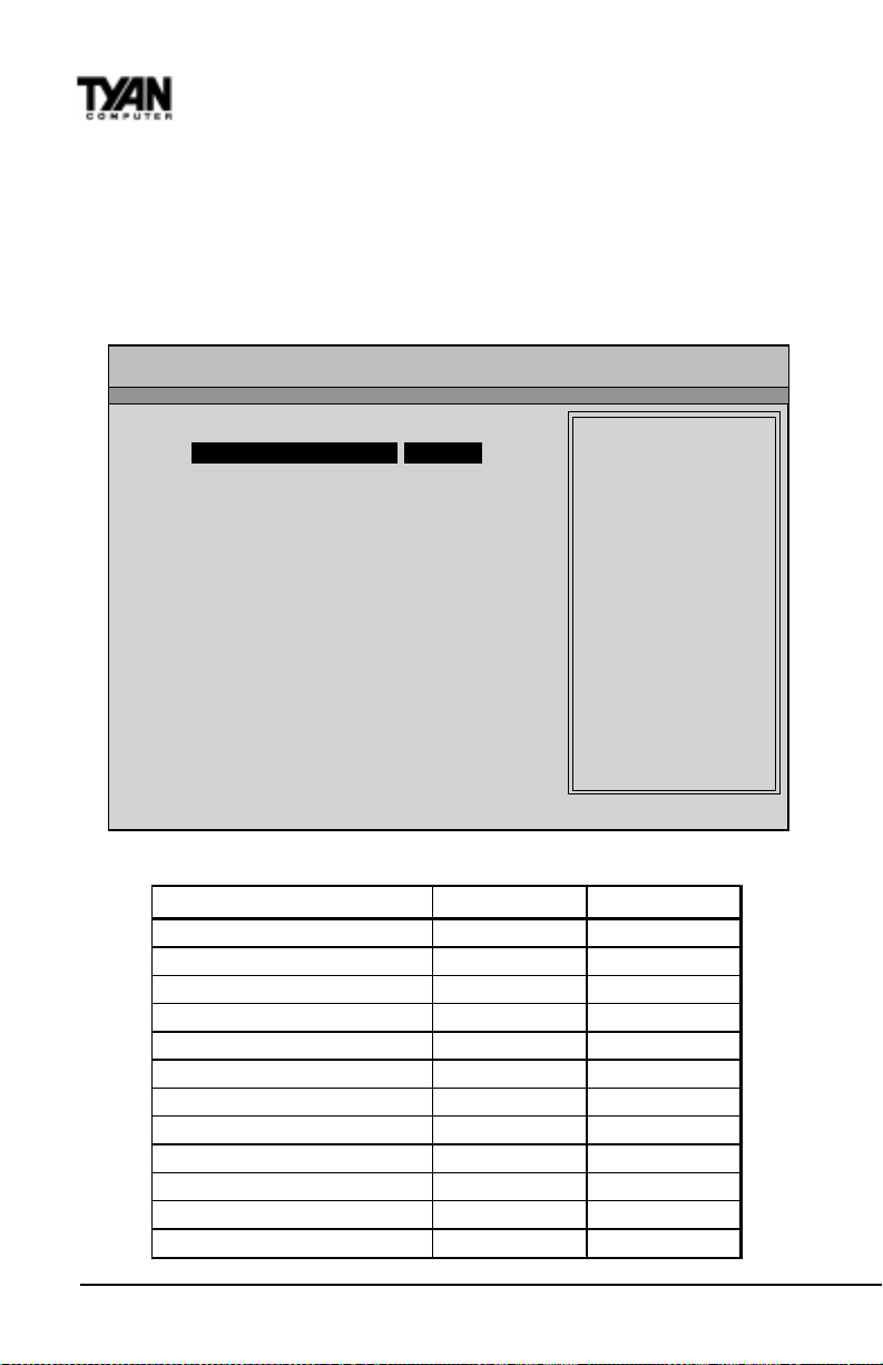
Chapter 4
BIOS Configuration
Chipset Setup
Choose Chipset Setup on the AMIBIOS Setup main menu. All Chipset Setup
options are then displayed. AMIBIOS Setup can be customized. AMIBIOS
Setup can be customized via AMIBCP . See the AMIBIOS Utilities Guide for
additional information.
AMI BIOS EASY SETUP UTILITY Ver.1.16
(c)1998 American Megatrends, Inc. All Rights Reserved
Advanced
Advanced CMOS Setup [ Enter ] Setup Help
Advanced Chipset Setup [ Enter ]
Power Management Setup [ Enter ] Advanced Chipset setup
Plug and Play Setup [ Enter ] for configuring
Peripheral Setup [ Enter ] chipset features
Change Language Setting Engish
- Previous Item
¯ Next Item
Select Menu
®¬
ESC:Exit Enter:Select F5:Setup Defaults F6:Original Values F10:Save & Exit
Advanced Chipset Setup Default Settings Chart
Setting Option Optimal Default Fail-Safe Default
USB Funct io n Disabled Dis abled
* US B K B /M ous e L egacy S uppo r t Dis abl ed Dis abled
* Port 64/60 Emulation Disa bled Disable d
SERR# Disable d Disabled
PERR# D isabled Disabled
WSC# Hand shake Enabled Enabled
US WC Wr ite P os t E nabled E nabled
Maste r Latency Timer (C lks) 64 64
Multi-Tran s T ime r ( Clks ) 32 32
PCI1 to PCI 0 Access Disabled Disabled
Method of Mem ory Detec tion Auto & SP D Aut o & SPD
DRAM In t egrity Mode ECC Hardware ECC Hardwa re
http://www.tyan.com
66
Page 67

Settings Chart (continued)
Setting Option Optimal Default Fail-Safe Default
D R A M R e fr es h R at e 15 .6 u s 15 .6 us
Memory Hole Disabled Disa bled
SD RAM RAS# to CAS# Delay 3SCLKs 3SCLK s
SD RAM RAS# Prech arge 3 SCLK s 3SCLKs
P o wer Do wn S D R A M Di s abled D is abl ed
A CPI Co nt rol Regi ster Disabled Disabl ed
G ated Cloc k Disabled Disable d
Graphic s Ap erture Size 64 MB 64 MB
S earch fo r M DA R es our ces Yes Yes
AGP Multi- Trans Timer (AGP Clks) 32 D isabled
A GP Low- Pri or it y Ti mer (Clk s ) 16 D isabl ed
AG P SERR Disabled Disa bled
A GP Par it y Error Response Disabled D isabled
8b it I/O Recovery Time Dis ab le d Disabled
16bit I/O R eco v ery T ime D i s abled Dis abled
PIIX4 SERR # Dis able d Disa ble d
USB P a ssive Re le as e Enabled Enable d
PIIX4 Pass ive Releas e Enab le d Ena bled
PIIX4 Delay ed Transa ction Dis ab led Dis able d
T ype F D MA B uf fer Contr ol1 Dis abled D is abled
T ype F D MA B uf fer Contr ol2 Dis abl ed D is abled
DMA-0 T yp e Norma l ISA Normal ISA
DMA-1 T ype Norma l ISA Normal ISA
DMA-2 T yp e Norma l ISA Normal ISA
DMA-3 T yp e Normal ISA Norma l ISA
DMA-4 T yp e Norma l ISA Normal ISA
DMA-5 T yp e Norma l ISA Normal ISA
DMA-6 T yp e Norma l ISA Normal ISA
BIOS
* Setting option not selectable.
USB Function
Set this option to Enabled to enable USB (Universal Serial Bus) support. The
settings are Enabled or Disabled.
S1836 Thunder 100
67
Page 68

Chapter 4
BIOS Configuration
USB KB/Mouse Legacy Support
Set this option to Enabled to enable support for older keyboards and mouse
devices if the USB Function option is set to Enabled. The settings are Enabled
or Disabled.
Port 64/60 Emulation
Setting this option to Enabled allows a USB keyboard to act like a legacy
keyboard. If this option is not Enabled, USB keyboard lights will not work
under Windows NT. With other operating systems, a USB keyboard will work
normally with this option Disabled. The settings are Enabled or Disabled.
SERR#
Set this option to Enabled to enable the SERR# signal on the bus. The settings
are Enabled or Disabled.
PERR#
Set this option to Enabled to enable the PERR# signal on the bus. The settings
are Enabled or Disabled. The Optimal and Fail-safe default settings are
Disabled.
WSC# Handshake
Set this option to Enabled to enable handshaking for the WSC# signal.
Handshaking is a form of encryption; see the Glossary for more information.
The settings are Enabled or Disabled.
USWC Write Post
This option sets the status of USWC posted writes to I/O. USWC is a type of
memory that is used by VGA devices. The settings are:
gnitteSnoitpircseD
delbanE.delbaneeraO/IotsetirwdetsopCWSU
delbasiD.delbasideraO/IotsetirwdetsopCWSU
BX Master Latency Timer (Clks)
This option specifies the master latency timer (in PCI clocks) for devices in the
computer. The settings are Disabled, 32, 64, 96, 128, 160, 192, or 224.
Multi-T rans Timer (Clks)
This option specifies the multi-trans latency timings (in PCI clocks) for devices
in the computer. The settings are Disabled, 32, 64, 96, 128, 160, 192, or 224.
http://www.tyan.com
68
Page 69
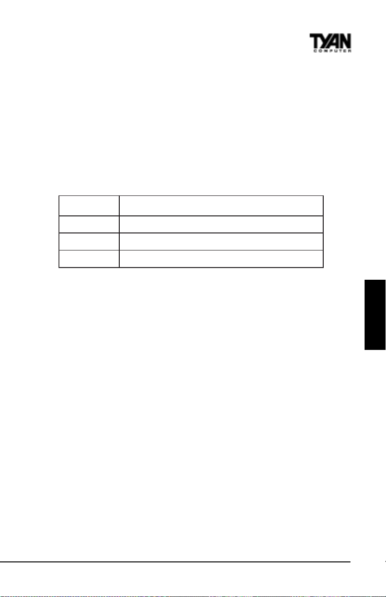
PCI1 to PCI0 Access
Set this option to Enabled to enable access between two different PCI buses
(PCI1 and PCI0). The settings are Enabled or Disabled.
Method of Memory Detection
This option determines how your system will detect the type of system
memory you have installed. Options are Auto+SPD or Auto only .
DRAM Integrity Mode
This option sets the type of system memory checking. The settings are:
gnitteSnoitpircseD
CCEnoN .enodsignitroperrorrerognikcehcrorreoN
CE .edameblliwsnoitcerrocontub,detcetederasrorrE
erawdraHCCE .detcerrocerasrorretibelgnisdna,detcetederasrorrE
DRAM Refresh Rate
This option specifies the interval between refresh signals to DRAM system
memory . The settings are 15.6 us (microseconds), 31.2 us, 62.4 us, 124.8 us, or
249.6 us.
Memory Hole
This option specifies the location of an area of memory that cannot be
addressed on the ISA bus. The settings are Disabled, 512KB-640KB, or 15MB16MB.
BIOS
SDRAM RAS# to CAS# Delay
This option specifies the length of the a inserted between the RAS and CAS
signals of the DRAM system memory access cycle if SDRAM is installed. The
settings are Auto, 2 SCLKs or 3 SCLKs. The Optimal default setting is Auto.
SDRAM RAS# Precharge
(CHANGE) This option specifies the length of the RAS precharge part of the
DRAM system memory access cycle when SDRAM system memory is
installed in this computer. The settings are Auto, 2 SCLKs, or 3 SCLKs.
Power Down SDRAM
If this option is set to Enabled, the SDRAM Power Down feature is enabled.
The settings are Enabled or Disabled.
S1836 Thunder 100
69
Page 70

Chapter 4
BIOS Configuration
ACPI Control Register
Set this option to Enabled to enable the ACPI (Advanced Configuration and
Power Interface) control register. The settings are Enabled or Disabled. The
Optimal and Fail-safe default settings are Enabled.
Gated Clock
Set this option to Enabled to enable the gated clock. The settings are Enabled
or Disabled.
Graphics Aperture Size
This option specifies the amount of system memory that can be used by the
Accelerated Graphics Port (AGP). The settings are 4 MB, 8 MB, 16 MB, 32 MB,
64 MB, 128 MB, or 256 MB.
Search for MDA Resources
Set this option to Yes to let AMIBIOS search for MDA resources. The settings
are Y es or No.
AGP Multi-T rans Timer (AGP Clks)
This option sets the AGP multi-trans timer. The settings are in units of AGP
Clocks. The settings are Disabled, 32, 64, 96, 128, 160, 192, or 224.
AGP Low-Priority Timer (Clks)
This option sets the AGP low priority timer. The settings are in units of AGP
Clocks. The settings are Disabled, 16, 32, 48, 64, 80, 96, 112, 128, 144, 176, 192,
208, 224, or 240.
AGP SERR
Set this option to Enabled to enable the AGP SERR signal. The settings are
Enabled or Disabled.
AGP Parity Error Response
Set this option to Enabled to enable AGP parity error response. The settings
are Enabled or Disabled.
8bit I/O Recovery Time
This option specifies the length of a delay inserted between consecutive 8-bit
I/O operations. The settings are Disabled and from 1 to 8 Sysclk (system
clocks) in increments of one.
http://www.tyan.com
70
Page 71

16bit I/O Recovery Time
This option specifies the length of a delay inserted between consecutive 16-bit
I/O operations. The settings are Disabled and from 1 to 4 Sysclk (system
clocks) in increments of one.
PIIX4 SERR#
Set this option to Enabled to enable the SERR# signal for the Intel PIIX4 chip.
The settings are Enabled or Disabled.
USB Passive Release
Set this option to Enabled to enable passive release for USB. The settings are
Enabled or Disabled.
PIIX4 Passive Release
Set this option to Enabled to enable passive release for the Intel PIIX4e chip.
This option must be Enabled to provide PCI 2.1 compliance. The settings are
Enabled or Disabled.
PIIX4 DELA YED TRANSACTION
Set this option to Enabled to enable delayed transactions for the Intel PIIX4
chip. This option must be Enabled to provide PCI 2.1 compliance. The settings
are Enabled or Disabled.
T ypeF DMA Buffer Control1 and 2
These options specify the DMA channel where TypeF buffer control is
implemented. The settings are Disabled, Channel-0, Channel-1, Channel-2,
Channel-3, Channel-5, Channel-6, or Channel-7.
BIOS
DMA-n T ype
These options specify the bus that the specified DMA channel can be used
on. The settings are Normal ISA, PC/PCI, or Distributed.
CPU Bus Frequency
This option provides selective CPU Bus Frequency; however, it is strongly
recommended that the default setting (Auto) be selected. Unpredictable
situations may arise if the Intel default CPU bus speed is not used. The
settings are Auto, 66.8MHz, 68.5MHz, 75MHz, 83.3MHz, 100MHz, 103MHz, or
112MHz.
S1836 Thunder 100
71
Page 72
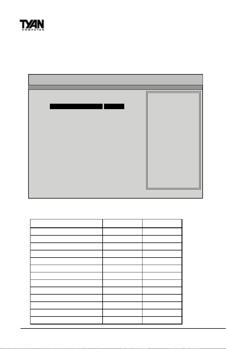
Chapter 4
BIOS Configuration
Power Management Setup
The AMIBIOS Setup options described in this section are selected by choosing Power Management Setup from the AMIBIOS Setup main menu.
AMI BIOS EASY SETUP UTILITY Ver.1.16
(c)1998 American Megatrends, Inc. All Rights Reserved
Advanced
Advanced CMOS Setup [ Enter ] Setup Help
Advanced Chipset Setup [ Enter ]
Power Management Setup [ Enter ] Power management setup
Plug and Play Setup [ Enter ] for configuring power
Peripheral Setup [ Enter ] management features
Change Language Setting English
- Previous Item
¯ Next Item
Select Menu
®¬
ESC:Exit Enter:Select F5:Setup Defaults F6:Original Values F10:Save & Exit
Power Management Setup Default Settings Chart
Setting Optio n Optimal D efa ult Fail -Safe Default
ACPI Aware O/S No No
P owe r Manag eme nt / AP M E nab led E nab led
Pow e r Button Fun c tion On /O ff On/O ff
Gr een PC Monitor Po wer State Suspend Stand By
Video P o wer Down Mode S us pend Di s abled
Ha rd Disk Powe r Down Mode Susp end Disa bled
Ha rd DiskT ime O ut ( Min u t e) Disa bled Disa ble d
Power Saving Type Sl eep Sl eep
S tand by / Sus pe nd Timer Unit 4 min 4 min
Sta ndb y Time Out Dis abled Disa ble d
Suspe n d Time O ut Disabled Disabled
Slow C lock Ra tio 50% - 62.5% 50% - 62.5%
Dis pla y Ac tivity Ignore Ign ore
http://www.tyan.com
72
Page 73
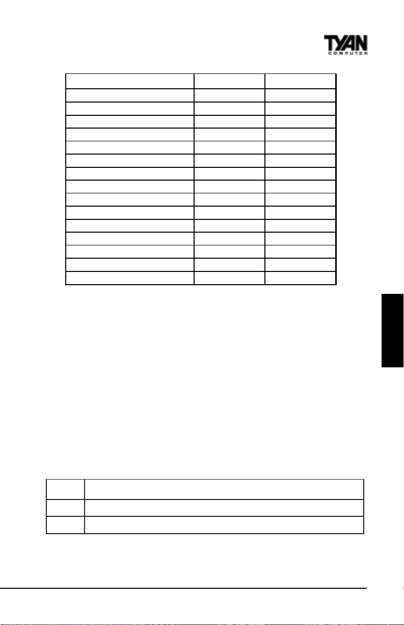
Setting Option Optimal Default Fail-Safe Default
Devic e 6 (Serial p ort 1) Monitor Monitor
Devic e 7 (Serial p ort 2) Monitor Monitor
Devic e 8 (Pa rallel p ort) Monitor Monitor
Devic e 5 (Floppy d isk) Monitor Monitor
Device 0 (P rimary mas ter IDE) Monitor Monitor
De vice 1 ( Primary slave IDE) Monitor Monitor
De vice 2 ( Secondary master IDE) Monitor Mon itor
De vice 3 ( Secondary slave I DE) Monit or Monitor
LAN Wake-up For Add on LAN Disabled Disabled
L A N Wake-up F o r Onboard L AN Dis abled D is abled
PC 9 8 Po wer L E D D isabl ed Disabled
F an O FF at Sus pend Enabled E nabled
RT C W ake -up Dis able d Disable d
*Hour N/A N/A
*Minute N/A N/A
* Setting option not selectable.
ACPI A ware O/S
Set this option to Yes to enable Advanced Configuration and Power Interface
(ACPI) BIOS for an ACPI-aware operating system.
Power Management/APM
Set this option to Enabled to enable the chipset power management and APM
(Advanced Power Management) features. The settings are Enabled or Disabled.
BIOS
Power Button Function
This option specifies how the power button mounted externally on the
computer chassis is used. See Soft Power Connector on page 31 for more
information. The settings are shown in the table below.
gnitteSnoitpircseD
ffO/nO.fforonoretupmocehtsnrutnottubrewopehtgnihsuP
dnepsuS .edomrewopnOlluFroedomdnepsuSniretupmocehtsecalpnottubrewopehtgnihsuP
Green PC Monitor Power State
This option specifies the power state that the green PC-compliant video
S1836 Thunder 100
73
Page 74

Chapter 4
BIOS Configuration
monitor enters when AMIBIOS places it in a power saving state after the
specified period of display inactivity has expired. The settings are Off, Stand
By , or Suspend.
Video Power Down Mode
This option specifies the power state that the video subsystem enters when
AMIBIOS places it in a power saving state after the specified period of display
inactivity has expired. The settings are Stand By , Suspend, or Disabled.
Hard Disk Power Down Mode
This option specifies the power conserving state that the hard disk drive
enters after the specified period of hard drive inactivity has expired. The
settings are Disabled, Stand By, or Suspend.
Hard Disk Time Out (Minute)
This option specifies the length of a period of hard disk drive inactivity . When
this length of time expires, the computer enters power-conserving state
specified in the Hard Disk Power Down Mode option (see the previous page).
The settings are Disabled, and from 1 to 15 minutes, in one minute intervals.
Power Saving T ype
There are several types of sleeping states within the general sleep state. This
option allows you to choose how “asleep” you want your system to be. In
deeper sleep modes, more energy is saved. However, upon waking up, the
system must “reorient” itself, and reestablish control over the system’s
sleeping components. The settings are POS, Sleep, Stop Clock, and Deep
Sleep. POS is the lightest sleep mode; Deep Sleep is the heaviest.
Standby/Suspend Timer Unit
This option specifies the unit of time used for the Standby and Suspend time
out periods. The settings are 4 msec, 4 sec, 32 sec, or 4 min.
Standby Time Out
This option defines the length of time that the system, while in Full On state,
must be inactive before it enters Standby mode. The settings are Disabled and
from 4 minutes to 508 minutes, in increments of 4 minutes.
Suspend Time Out
This option defines the length of time that the system, while in Standby mode,
must be inactive before it enters Suspend mode. The settings are Disabled and
from 4 minutes to 508 minutes, in increments of 4 minutes.
http://www.tyan.com
74
Page 75

Slow Clock Ratio
This option specifies the speed at which the system clock runs in the Standby
Mode power saving state. The settings are expressed as a percentage of the
normal CPU clock speed. The settings are 0-12.5%, 12.5%-25%, 25%-37.5%,
37.5%-50%, 50%-62.5%, 62.5%-75%, or 75-87.5%.
Display Activity
When set to Monitor, this option enables event monitoring on the video
display. If set to Monitor and the computer is in a power saving state, display
activity will cause the system to enter the Full On state. AMIBIOS reloads the
Standby and Suspend time-out timers if display activity occurs. The settings
are Monitor or Ignore.
Device n (Device identity)
When set to Monitor, these options enable event monitoring on the specified
hardware interrupt request line. If set to Monitor and the computer is in a
power saving state, any activity on the IRQ line will cause the system to enter
the Full On state. AMIBIOS reloads the Standby and Suspend time-out timers
if activity occurs on the specified IRQ line. The settings for each of these
options are Monitor or Ignore.
LAN Wake-up
When this option is Enabled, the system will wake up when a signal is received
on the W ake-on LAN header . In order for this wake up function to work, the
system must have been brought up at least past the POST before it was last
shut down (i.e. if you turn the system off before the POST, the registry will not
be set, and the system will not be able to wake up using this function). This
function requires an A TX 2.01 compliant power supply with 5V standby
(STB5V) current of at least 800mA. The settings are Enabled or Disabled.
BIOS
PC98 Power LED
When this option is Enabled, your power LED will turn to yellow when your
system is in Suspend mode. Note that if you do not have a two-color LED,
your LED will turn off when the system is in Suspend mode if this option is set
to Enabled. The settings are Enabled or Disabled.
F AN OFF at Suspend
If this option is Enabled, the CPU fan will turn off when the system is in
Suspend mode. If Disabled, the CPU fan will remain on while the system is in
Suspend mode. The settings are Enabled or Disabled.
S1836 Thunder 100
75
Page 76
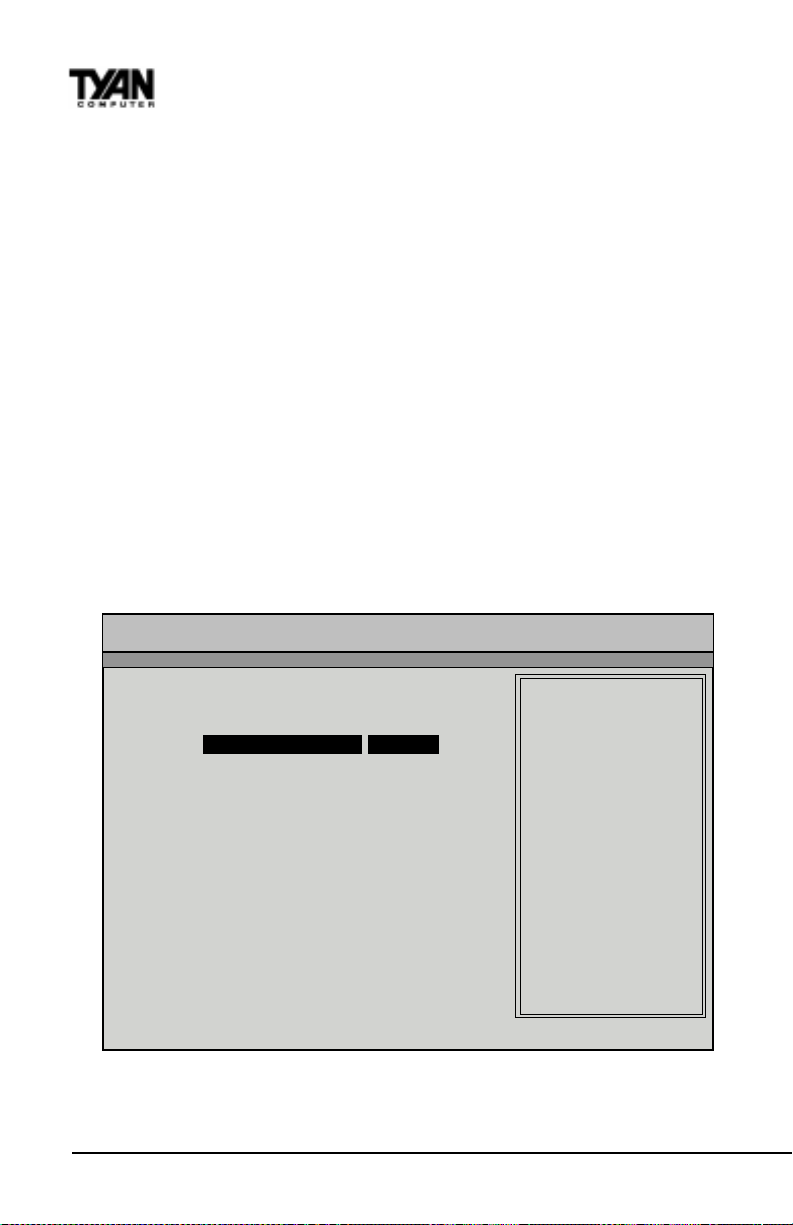
Chapter 4
BIOS Configuration
RTC Wake-up
If Enabled, this option allows you to set an hour and minute for the system to
wake up. The next two fields allow you to choose the wake up time. Note that
the time fields will not be available if this option is set to Disabled. In order for
this wake up function to work, the system must have been brought up at least
past the POST before it was last shut down (i.e. if you turn the system off
before the POST , the registry will not be set, and the system will not be able to
wake up using this function). The settings are Enabled or Disabled.
Plug and Play Setup
Choose PCI/Plug and Play Setup from the AMIBIOS Setup screen to display
the PCI and Plug and Play Setup options, described below.
AMI BIOS EASY SETUP UTILITY Ver.1.16
(c)1998 American Megatrends, Inc. All Rights Reserved
Advanced
Advanced CMOS Setup [ Enter ] Setup Help
Advanced Chipset Setup [ Enter ]
Power Management Setup [ Enter ] Configure PCI / Plug
Plug and Play Setup [ Enter ] and Play features
Peripheral Setup [ Enter ]
Change Language Setting English
- Previous Item
¯ Next Item
Select Menu
®¬
ESC:Exit Enter:Select F5:Setup Defaults F6:Original Values F10:Save & Exit
http://www.tyan.com
76
Page 77
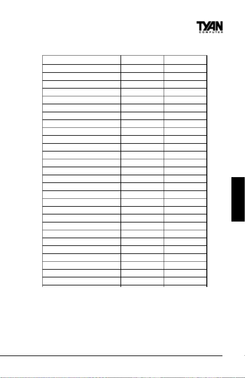
Plug and Play Setup Default Settings Chart
Setting Option Optimal Default Fail-Safe Default
P lug and P lay A ware O/S Y es Y es
P CI Latenc y T imer (P CI Clocks ) 64 64
PCI VGA Palet te Snoop Disabled Disabled
Alloca te IRQ to PCI VGA Yes Yes
PCI IDE B us Master Dis a bled Dis a bled
OffBoa rd PCI IDE Card Auto Auto
*OffB oard PCI IDE P rima ry IRQ Dis ab le d Dis able d
*OffB oard PCI IDE Secondary IRQ Dis a bled Dis a bled
PCI Slot1 IRQ Priority Auto Auto
PCI Slot2 IR Q Priority Auto Auto
PCI Slot3 IR Q Priority Auto Auto
PCI Slot4 IR Q Priority Auto Auto
DM A Channel 0 P nP P nP
DM A Channel 1 P nP P nP
DM A Channel 3 P nP P nP
DM A Channel 5 P nP P nP
DM A Channel 6 P nP P nP
DM A Channel 7 P nP P nP
IRQ3 PCI/PnP PCI/PnP
IRQ4 PCI/PnP PCI/PnP
IRQ5 PCI/PnP PCI/PnP
IRQ7 PCI/PnP PCI/PnP
IRQ9 PCI/PnP PCI/PnP
IRQ10 PCI/PnP PCI/PnP
IRQ11 PCI/PnP PCI/PnP
IRQ12 PCI/PnP PCI/PnP
IRQ14 PCI/PnP PCI/PnP
IRQ15 PCI/PnP PCI/PnP
BIOS
* Setting option is not selectable
S1836 Thunder 100
77
Page 78

Chapter 4
BIOS Configuration
Plug and Play A ware O/S
Set this option to Yes to inform AMIBIOS that the operating system can
handle plug and Play (PnP) devices. The settings are No or Yes.
PCI Latency Timer (PCI Clocks)
This option specifies the latency timings (in PCI clocks) for PCI devices
installed in the PCI expansion slots. The settings are 32, 64, 96, 128, 160, 192,
224, or 248.
PCI VGA Palette Snoop
When this option is set to Enabled, multiple VGA devices operating on
different buses can handle data from the CPU on each set of palette registers
on every video device. Bit 5 of the command register in the PCI device
configuration space is the VGA Palette Snoop bit (0 is disabled). For example, if
there are two VGA devices in the computer (one PCI and one ISA) and this
field is set for:
gnitteSnoitpircseD
delbasiD .sretsigerettelaps'ecivedAGVICPehtotdetceridylnosiUPCehtybnettirwdnadaerataD
delbanE
.lacitnediebotsecivedhtobfosretsigerettelapehtgnittimrep,sretsigerettelapecivedAGVASIeht
dnasretsigerettelaps'ecivedAGVICPehthtobehtotdetceridsiUPCehtybnettirwdnadaerataD
This option must be set to Enabled if any ISA adapter card installed in the
system requires VGA palette snooping.
Allocate IRQ to PCI VGA
Set this option to Y es to allocate an IRQ to the VGA device on the PCI bus.
The settings are Yes or No.
PCI IDE BusMaster
Set this option to Enabled to specify that the IDE controller on the PCI bus has
bus mastering capability . The settings are Disabled or Enabled.
OffBoard PCI IDE Card
This option specifies whether or not an offboard PCI IDE controller adapter
card is used in the computer, and where it is installed. If an offboard PCI IDE
controller is used, the motherboard onboard IDE controller is automatically
disabled. The settings are Auto and Slot1 through Slot6. If Auto is selected,
AMIBIOS automatically determines the correct setting (including using the
onboard controller if no offboard controller card is detected). This option
forces IRQ 14 and 15 to a PCI slot on the PCI local bus. This is necessary to
http://www.tyan.com
78
Page 79

support non-compliant PCI IDE adapter cards.
OffBoard PCI IDE Primary IRQ
This option specifies the PCI interrupt used by the primary IDE channel on the
offboard PCI IDE controller . The settings are Disabled, Hardwired, INT A,
INTB, INTC, or INTD.
Offboard PCI IDE Secondary IRQ
This option specifies the PCI interrupt used by the secondary IDE channel on
the offboard PCI IDE controller . The settings are Disabled, Hardwired, INT A,
INTB, INTC, or INTD.
PCI Slot n IRQ Priority
These options specify the IRQ priority for PCI devices installed in the PCI
devices installed in the PCI expansion slots. The settings are Auto, IRQ 3, 4, 5,
7, 9, 10, and 11, in priority order .
DMA Channel n
These options allow you to specify the bus type used by each DMA channel.
The settings are PnP or ISA/EISA .
IRQn
These options specify the bus that the specified IRQ line is used on. These
options allow you to reserve IRQs for legacy ISA adapter cards. These options
determine if AMIBIOS should remove an IRQ from the pool of available IRQs
passed to devices that are configurable by the system BIOS. The available IRQ
pool is determined by reading the ESCD NVRAM. If more IRQs must be
removed from the pool, you can use these options to reserve the IRQ by
assigning an ISA/EISA setting to it. Onboard I/O is configured by AMIBIOS.
All IRQs used by onboard I/O are configured as PCI/PnP. IRQ12 only appears
if the Mouse Support option in Advanced Setup is set to Disabled. IRQ14 and
15 will not be available if the onboard PCI IDE is enabled. If all IRQs are set to
ISA/EISA and IRQ14 and 15 are allocated to the onboard PCI IDE, IRQ9 will
still be available for PCI and PnP devices, because at least one IRQ must be
available for PCI and PnP devices. The settings are ISA/EISA or PCI/PnP .
BIOS
Reserved Memory Size
This option specifies the size of the memory area reserved for legacy ISA
adapter cards. The settings are Disabled, 16K, 32K, or 64K.
S1836 Thunder 100
79
Page 80

Chapter 4
BIOS Configuration
Reserved Memory Address
This option specifies the beginning address (in hex) of the reserved memory
area. The specified ROM memory area is reserved for use by legacy ISA
adapter cards. This option does not appear if the Reserved Memory Size
option is set to Disabled. The settings are C0000, C4000, C8000, CC000, D0000,
D4000, D8000, or DC000.
PCI Device Search Order
This option changes the BIOS scan order of the PCI slot - from first to last or
last to first. The settings are First-Last or Last-First.
BIOS Devnode for Shadow RAM
This option is used for some add-on card ROMs which do not claim the
correct memory range that they occupy . The settings are Disabled or Enabled.
80
http://www.tyan.com
Page 81
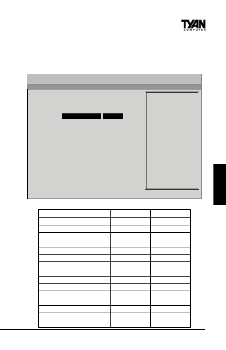
Peripheral Setup
Peripheral Setup options are displayed by choosing Peripheral Setup from the
AMIBIOS Setup main menu. All Peripheral Setup options are described here.
AMI BIOS EASY SETUP UTILITY Ver.1.16
(c)1998 American Megatrends, Inc. All Rights Reserved
Advanced
Advanced CMOS Setup [ Enter ] Setup Help
Advanced Chipset Setup [ Enter ]
Power Management Setup [ Enter ] Configure PCI / Plug
Plug and Play Setup [ Enter ] and Play features
Peripheral Setup [ Enter ]
Change Language Setting English
- Previous Item
¯ Next Item
Select Menu
®¬
ESC:Exit Enter:Select F5:Setup Defaults F6:Original Values F10:Save & Exit
Peripheral Setup Default Settings Chart
Setting Option O ptimal Default Fail-Safe D efaul t
OnB oar d S CS I E nabled Enabled
Power Interru ption Disa bled Disa bled
Overclock Warning Mes s age E nabled Enabled
Fl oppy Mode Regul ar Regular
Onb oard F DC Auto Auto
O nboard Serial Port 1 3F8h 3F8h
O nboard Serial Port 2 2F8h 2F8h
Serial Port 2 Mode Normal Normal
* IR Duplex Mod e N/A N/A
*R eceiver P olarity N/A N/A
* Transmitter P olarity N/A N/A
* Fast IR P ort N/A N/A
* Fast IR DMA N/A N/A
On board Pa rallel Port 378 378
Parallel Port Mode Normal Normal
S1836 Thunder 100
81
BIOS
Page 82

Chapter 4
BIOS Configuration
Settings Chart (Continued)
Setting Option O ptimal Default Fail-Safe D efaul t
*E P P Vers ion N/A N/A
Parallel Port IRQ 7 7
*P aral l el P o rt DM A Channel N/A N /A
On board IDE Both B oth
Onboard SCSI
Select ‘Enabled’ to use onboard SCSI. The settings are Enabled or Disabled.
External Onboard SCSI LED
Set this option to Enabled to direct the SCSI (onboard or add-on card) LED to
the front panel.
Power Interruption
The settings are Enabled or Disabled.
Onboard FDC
Set this option to Enabled to enable the floppy drive controller on the motherboard. The settings are Auto, Enabled, or Disabled.
Onboard Serial Port1
This option specifies the base I/O port address of serial port 1. The settings
are Auto, Disabled, 3F8h, 2F8h, 3E8h, or 2E8h.
Onboard Serial Port2
This option specifies the base I/O port address of serial port 2. The settings
are Auto, Disabled, 3F8h, 2F8h, 3E8h, or 2E8h.
Serial Port2 Mode
This option specifies the operating mode for serial port 2. This option will not
appear if the Onboard Serial Port2 option is set to Disabled, or is set to Auto
and your system does not have an onboard serial port 2. The settings are
Normal, Sharp-IR, IrDA, and Consumer.
IR T ransmission Mode
This option specifies the infrared transmission method. This option will not
appear if the Serial Port2 Mode option is set to Normal. The settings are Full or
Half.
http://www.tyan.com
82
Page 83
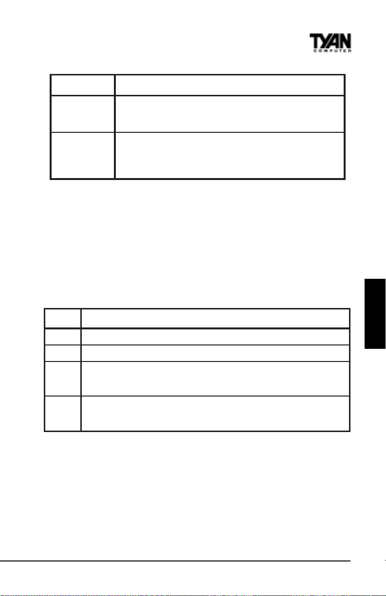
edoMnoitpircseD
xelpuDlluF
xelpuDflaH
.edomxelpud
tonlliwdnesuoyatadynA.ecnotasnoitceridowtnidettimsnartsiataD
ecivedrehtoehtybdeviecerneebsahtilitnuneercsruoynoraeppa
.sedomowtehtforetsafehtsixelpudlluF.uoyotkcabtnesdna
dnesuoyatadynA.emitatanoitceridenoylnonidettimsnartsiataD
reisaesiedomxelpudflaH.neercsruoynodeyalpsidyltnatsnieblliw
llufeldnahnacsecivedelbapac-RIllatoN.etucexeotsecivedehtrof
IR Receiver Pin
This option specifies which pin will act as the receiver for IR data transmission.
This option will not appear if the Serial Port2 Mode option is set to Normal.
The only setting is IRRX1.
OnBoard Parallel Port
This option specifies the base I/O port address of the parallel port on the
motherboard. The settings are Auto, Disabled, 378, or 278.
Parallel Port Mode
This option specifies the parallel port mode. The settings are:
gnitteSnoitpircseD
lamroN.desusiedomtroplellaraplamronehT
riD-iB.troplellarapehtnosrefsnartlanoitceridibtroppusotgnittessihtesU
PPE
.ecivedtsohehtybnevirdrefsnartatadlanoitceridib
troPlellaraPdecnahnEehtoterehdatahtsecivedhtiwdesuebnactroplellarapehT
cirtemmysaedivorpotslangistroplellarapgnitsixeehtsesuPPE.snoitacificeps)PPE(
BIOS
PCE
EPP V ersion
This option specifies the Enhanced Parallel Port specification version number
that is used in the system. This option only appears if the Parallel Port Mode
option is set to EPP . The settings are 1.7 or 1.9. Version 1.9 is common on
newer devices; consult your device’s user information for the appropriate port
type. There are no default settings.
Parallel Port IRQ
This option specifies the IRQ used by the parallel port, and only appears if
S1836 Thunder 100
83
troPseitilibapaCdednetxEehtoterehdatahtsecivedhtiwdesuebnactroplellarapehT
pufosetarrefsnartatadeveihcaotlocotorpAMDehtsesuPCE.snoitacificeps)PCE(
.noitacinummoclanoitceridibcirtemmyssedivorpPCE.dnocesrepstibageM5.2ot
Page 84
Chapter 4
BIOS Configuration
OnBoard Parallel Port is set to 278 or 378. The settings are 5 or 7.
Parallel Port DMA Channel
This option is only available if the setting for the Parallel Port Mode option is
set to ECP and the OnBoard Parallel Port option is set to 378, 278, or 3BC. This
option sets the DMA channel used by the parallel port. The settings are 0
through 7 in increments of one.
Onboard IDE
This option specifies the IDE channel used by the onboard IDE controller. The
settings are Disabled, Primary , Secondary , or Both.
Supervisor and User Security
You can limit access to the Setup Program or to the system using the Supervisor and User password options (the Supervisor password gives you access to
the Setup Program and the system; the User password, only to the system).
Note that you must create a supervisor password before you create a user
password.
AMI BIOS EASY SETUP UTILITY Ver.1.16
(c)1998 American Megatrends, Inc. All Rights Reserved
Main Advanced Security Exit
Set Supervisor Password [ Enter ] Setup Help
Set User Password [ Enter ]
ESC:Exit Enter:Select F5:Setup Defaults F6:Original Values F10:Save & Exit
84
Change the supervisor
password
- Previous Item
¯ Next Item
Select Menu
®¬
http://www.tyan.com
Page 85

When you select the Supervisor Security option, a dialog box will appear,
allowing you to enter a password. You may either type the password in, or
click on the onscreen buttons. Your password must be between one and six
characters long.
Once you have entered your new password, you will be asked to confirm it. If
the two passwords do not match, you will be prompted to enter a new password, and then to confirm it. This will continue until you enter the same series
of characters both times. Once this is accomplished, a dialog box will appear
and notify you that the Supervisor Password has been installed. You may then
select the User Security option and enter a password for the user.
You can enter a new User password at any time simply by selecting the User
Security option, and typing in a new password. T o enter a new Supervisor
password, select the Supervisor Security option. You will be asked to enter the
current password. After you do so, you will be prompted to enter the new
password.
In either the Supervisor or User Security options, pressing <Enter> once when
asked for a new password, and a second time when asked to confirm the new
password, will uninstall the existing password. Note that uninstalling the
Supervisor password uninstalls the User password as well.
Language Utility
BIOS
Currently, the BIOS Setup program is available only in English.
Flash Writer Utility
The AMI Flash Writer Utility is now included in the AMIBIOS, and so it is
simpler to upgrade the BIOS of your mainboard. The system BIOS is stored on
a flash EEPROM ROM chip on the mainboard which can be erased and
reprogrammed by following the directions on the following page.
1. From the DOS prompt, rename the BIOS file that you have downloaded to
“amiboot.rom” and copy it on to a floppy disk.
2. Insert the floppy disk with the BIOS upgrade into the A: drive.
3. Turn the power off.
4. While holding the <Ctrl> and <Home> keys, turn the power on. The system
will begin to read from the A: drive, and write the BIOS information contained
on the floppy disk in that drive to the EEPROM ROM chip. When the BIOS
has been totally reprogrammed, the system will reboot with the new BIOS in
S1836 Thunder 100
85
Page 86

Chapter 4
BIOS Configuration
operation.
5. If the system does not reboot in three minutes, power down the system wait
a few seconds, and then turn the power back on again. You will be prompted to
press <F1> to run Setup. You may check your settings at this time, or simply
save and exit the program.
86
http://www.tyan.com
Page 87
chapter 5
System Resources
Beep Codes
Fatal errors, which halt the boot process, are communicated through a
series of audible beeps. If AMIBIOS POST can initialize the system
video display , it displays the error message. Displayed error messages,
in most cases, allow the system to continue to boot. Displayed error
messages are described on pages 89-90. See the top of the next page
for the beep code chart.
S1836 Thunder 100
87
Page 88

Chapter 5
System Resources
speeBegasseMrorrEnoitpircseD
1eruliaFhserfeR .ytluafsiyrtiucrichserferyromemehT
2rorrEytiraP .yromemfo)kcolbBK46tsrifeht(yromemesabehtnirorreytiraP
3eruliaFyromeMBK46esaB.BK46tsrifnieruliafyromeM
4lanoitarepOtoNremiT
5rorrErossecorP.rorrenadetarenegUPCehT
6eruliaF02AetaG-2408.edomdetcetorpothctiwstonnaC
7rorrEtpurretnInoitpecxErossecorP .tpurretninoitpecxenadetarenegdraCUPCehtnoUPCehT
8rorrEetirW/daeRyromeMyalpsiD
9rorrEmuskcehCMOR
01rorrEetirW/daeRretsigeRnwodtuhSSOMC .deliafsahMARSOMCrofretsigernwodtuhsehT
11
ehcaC
elbanEtoNoD—daByromeMehcaC
.gninoitcnuf
.rorrelatafatonsisihT
.SOIBIMA
nidedocneeulavehthctamtonseodeulavmuskcehcMORehT
.yromemehcacelbaneot>+<>tfihS<>tlA<>lrtC<sserp
T roubleshooting System Problems
If the computer beeps... then...
1, 2, or 3 times... reseat the memory SIMMs or
DIMMs. If the system still beeps,
replace the memory.
6 times... reseat the keyboard controller chip. If
it still beeps, replace the keyboard
controller. If it still beeps, try a
different keyboard, or replace the
keyboard fuse, if there is one.
8 times... there is a memory error on the video
adapter. Replace the video adapter, or
the RAM on the video adapter.
9 times... the BIOS ROM chip is bad. The
system probably needs a new BIOS
ROM chip.
11 times... reseat the cache memory on the
motherboard. If it still beeps, replace
the cache memory .
4, 5, 7, or 10 times... the motherboard must be replaced.
tonsi1remiTro,yromemfoBK46tsrifehtnieruliafyromemA
.ytluafsiyromemstirognissimrehtiesiretpadaoedivmetsysehT
tonoD.delbasidsiyromemehcaC.deliaftsetyromemehcacehT
88
http://www.tyan.com
Page 89

Displayed Error Messages
If an error occurs after the system display has been initialized, the error
message will be displayed as follows:
ERROR Message Line 1
ERROR Message Line 2
Press <F1> to continue
and the system will halt. The system will not halt if the W ait for <F1> If
Any Error option in Advanced Setup is Disabled.
RUN SETUP UTILITY
may also appear. Press <F1> to run WINBIOS Setup if this message
appears.
egasseMrorrEnoitanalpxE
rorrE02A-etaG2408 .2408ehtecalpeR.gnikrowtonsi)2408(rellortnocdraobyekehtno02AetaG
!trohSeniLsserddA.yrtiucricgnidocedsserddaehtnirorrE
rorrEevirD:C
eruliaFevirD:C.evirdehtecalpeR.:CevirdksiddrahmorfesnopseroN
,daByromeMehcaC
!ehcaCelbanEtoNoD
rorrEremiT2-HC.2remitnirorrenasierehT.sremitowtsahmetsysTAnA
woL
eruliaF
teStoN
etatSyrettaBSOMC
muskcehCSOMC
metsySSOMC
teStoNsnoitpO
epyTyalpsiDSOMC
hctamsiM
eziSyromeMSOMC
hctamsiM
rorrEevirD:D
.yrettab
.puteS
etaDdnaemiTSOMC
.puteSdradnatSniepytksid
.gaiDIMAnuR.evitcefedsiyromemehcaC
.puteSSOIBNIWnuR.MAR
.emitdnaetadehttesotputeSdradnatSnuR
.puteSdradnatSniepytksid
drah:CehtkcehC.ytilitUksiDdraHgaiDIMAehtnuR.:CevirdmorfesnopseroN
ehtecalpeR.wolsirewopyrettabehT.yrettabaybderewopsiMARSOMC
.puteSSOIBNIWnuR.eulavsuoiverpehtnahttnereffidsimuskcehcMARSOMC
.puteSSOIBNIWnuR.deyortsedneebevahMARSOMCniderotsseulavehT
SOIBNIWnuR.detcetedepytehthctamtonseodMARSOMCniepytoedivehT
SOMCnitnuomaehtnahttnereffidsiSOIBIMAybdnuofyromemfotnuomaehT
drahehtkcehC.ytilitUksiDdraHgaiDIMAehtnuR.:DevirdmorfesnopseroN
SYSTEM
S1836 Thunder 100
89
Page 90

Chapter 5
System Resources
egasseMrorrEnoitanalpxE
eruliafevird:D.evirdehtecalpeR.:DevirdksiddrahmorfesnopseroN
reporP
rorrEAMD.rellortnocAMDehtnirorrE
rorrE1AMD.lennahcAMDtsrifehtnirorrE
rorrE2AMD.lennahcAMDdnocesehtnirorrE
rorrE1RTNI.TSOPdeliaf1lennahctpurretnI
rorrE2RTNI.TSOPdeliaf2lennahctpurretnI
sIdraobyeK
rorrEdraobyeK
eruliaFtooBetteksiD
toNhctiwSyalpsiD
eruliaFrellortnoCDDF
eruliaFrellortnoCDDH
etteksiDtooBdilavnI
tIkcolnU...dekcoL
rorrEecafretnI/BK.rotcennocdraobyekehtnirorrenasierehT
.snoitcurtsnineercsehtwollofdnaetteksidtoobrehtona
esU.metsysehttoobotdesuebtonnac:AevirdnietteksidtoobehT
rorolocrehtieottesebhctiwsoedivaeriuqersmetsysemoS
.norewopneht,ylreporphctiwsehttes,ffometsysehtnruT.emorhconom
.rellortnocevirdksidyppolfehthtiwetacinummoctonnacSOIBIMA
.nwodderewopsimetsysehtretfasnoitcennocetairporppallakcehC
kcehC.rellortnocevirdksiddrahehthtiwetacinummoctonnacSOIBIMA
.nwodderewopsimetsysehtretfasnoitcennocetairporppalla
ehttoobtonnactitub,:AevirdyppolfnietteksidehtdaernacSOIBIMA
.snoitcurtsnineercsehtwollofdnaetteksidtoobrehtonaesU.tihtiwmetsys
ebtsummetsysehT.degagnesimetsysehtnokcoldraobyekehT
.tooboteunitnocotdekcolnu
rellortnoCdraobyeKaerusekaM.melborpgnimitasahdraobyekehT
dellatsnItoNotputeSdecnavdAnidraobyeKteS.dellatsnisiSOIBIMA
.senituorTSOPdraobyekehtpiksot
CISABMORoN
.cisaBMORdniftonnac
SOIBIMA.:Cro:AevirdrehtienorotceselbatoobreporpadniftonnaC
.tolsnoisnapxenanidracretpadananodellatsniyromemnirorreytiraP
rorrEytiraPdraoBffO
:sitamrofehT
)XXXX(=RDDARORREYTIRAPDRAOBFFO
dnadnifotgaiDIMAnuR.derruccororreehterehwsserddaxehehtsiXXXX
.smelborpyromemtcerroc
:sitamrofehT.yromemdraobrehtomnirorreytiraP
rorrEytiraPdraoBnO
)XXXX(=RDDARORREYTIRAPDRAOBNO
dnifotgaiDIMAnuR.derruccororreehterehwsserddaxehehtsiXXXX
.smelborpyromemtcerrocdna
????rorrEytiraP
.smelborpyromemtcerrocdnadnif
http://www.tyan.com
otgaiDIMAnuR.sserddanwonknunatayromemmetsysnirorreytiraP
90
Page 91
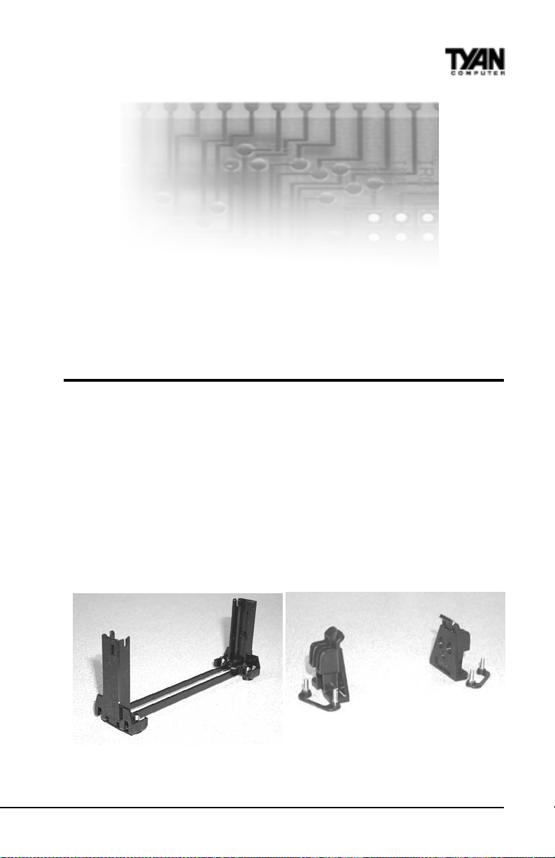
Appendix 1
CPU Retention Module Options
T yan offers two dif ferent options for securing Intel’ s Pentium II and Celeron
CPUs onto the motherboard. Each option provides retention for both older
Pentium II’ s as well as newer Pentium II’s (including Slot 1 type Celeron).
OPTION 1:
T wo dif ferent types of retention modules are included in the motherboard
package. For older versions of Pentium II, use the retention module shown in
Figure 1. For newer versions of Pentium II CPUs (including Slot 1 type
Celeron), use the retention module shown in Figure 2. (Screws for the retention modules are provided.)
Figure 1 Figure 2
S1836 Thunder 100
91
Page 92
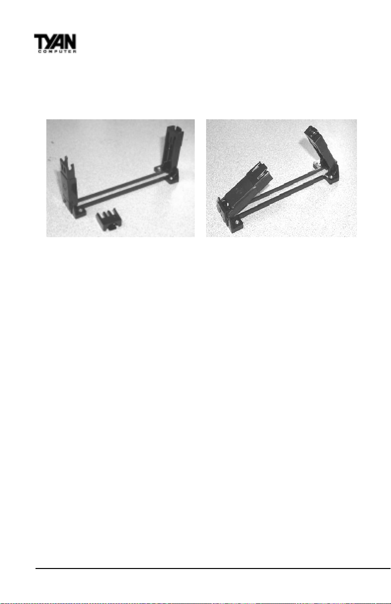
Appendix 1
CPU Retention Module Options
OPTION 2:
One universal retention module is included in the motheboard package. This
type of retention module adapts to both old and new Pentium II CPUs - see
Figure 3. (Screws for the retention modules are provided)
Figure 3
92
http://www.tyan.com
Page 93
Appendix 2
Glossary
ACPI (Advanced Configuration and Power Interface) is a power management
specification that allows the operating system to control the amount of power
distributed to the computer’s devices. Devices not in use can be turned off,
reducing unnecessary power expenditure.
AGP (Accelerated Graphics Port) is a PCI-based interface which was designed
specifically for demands of 3D graphics applications. The 32-bit AGP channel
directly links the graphics controller to the main memory. While the channel
runs at only 66MHz, 2X supports data transmission during both the rising and
falling ends of the clock cycle, yielding an effective speed of 133MHz.
The AT was the original form factor of IBM’s PC.
A T API (AT Attachment Packet Interface), also known as IDE or A TA, is a drive
implementation that includes the disk controller on the device itself. It allows
CD-ROMs and tape drives to be configured as master or slave devices, just
like hard drives.
The ATX form factor was designed to replace the AT form factor . It improves
on the AT design by rotating the board ninety degrees, so that the IDE
connectors are closer to the drive bays, and the CPU is closer to the power
supply and cooling fan. The keyboard, mouse, serial, USB, and parallel ports
S1836 Thunder 100
93
Page 94

Appendix 2
Glossary
are built in.
Bandwidth refers to carrying capacity. The greater the bandwidth, the more
data the bus, phone line, or other electrical path, can carry. Greater bandwidth,
then, also results in greater speed.
A BBS (Bulletin Board System) is a computer system with a number of
modems hooked up to it which acts as a center for users to post messages and
access information.
The BIOS (Basic Input/Output System) program resides in the ROM chip, and
provides the basic instructions for controlling your computer’s hardware. Both
the operating system and application software use BIOS routines to ensure
compatibility .
A buffer is a portion of RAM which is used to temporarily store data, usually
from an application, though it is also used when printing, and in most keyboard drivers. The CPU can manipulate data in a buffer before copying it, all at
once, to a disk drive. While this improves system performance--reading to or
writing from a disk drive a single time is much faster than doing so repeatedly-there is the possibility of losing your data should the system crash. Information stored in a buffer is temporarily stored, not permanently saved.
A bus is a data pathway. The term is used especially to refer to the connection
between the processor and system memory, and between the processor and
PCI or ISA local buses.
Bus mastering allows peripheral devices and IDEs to access the system
memory without going through the CPU (similar to DMA channels).
A cache is a temporary storage area for data that will be needed often by an
application. Using a cache lowers data access times, since the needed information is stored in the SRAM instead of in the slower DRAM. Note that the
cache is also much smaller than your regular memory: a typical cache size is
512KB, while you may have as much as 1GB of regular memory.
Cache size refers to the physical size of the cache onboard. This should not
be confused with the cacheable area, which is the total amount of memory
which can be scanned by the system in search of data to put into the cache. A
typical setup would be a cache size of 512KB, and a cacheable area of 512MB.
In this case, up to 512MB of the main memory onboard is capable of being
http://www.tyan.com
94
Page 95

cached. However, only 512KB of this memory will be in the cache at any given
moment. Any main memory above 512MB could never be cached.
Closed and open jumpers Jumpers and jumper pins are active when they are
On or Closed, and inactive when they are Off or Open.
CMOS Complementary Metal-Oxide Semiconductors are chips that hold the
basic start-up information for the BIOS.
The COM port is another name for the serial port, which is so-called because it
transmits the eight bits of a byte of data along one wire, and receives data on
another single wire (that is, the data is transmitted in serial form, one bit after
another). Parallel ports transmit the bits of a byte on eight different wires at the
same time (that is, in parallel form, eight bits at the same time).
DIMM Dual In-line Memory Modules are a faster and more capacious form of
RAM than SIMMs, and do not need to be installed in pairs.
DIMM bank DIMM banks are sometimes called DIMM sockets, because the
physical slot and the logical unit are the same. That is, one DIMM module fits
into one DIMM socket, which is capable of acting as a memory bank.
DMA Direct Memory Access channels are similar to IRQs. DMA channels allow
hardware devices (like sound cards or keyboards) to access the main memory
without involving the CPU. This frees up CPU resources for other tasks. As
with IRQs, it is vital that you do not double up devices on a single line. Plug
and Play devices will take care of this for you.
In Doze mode, only the CPU’s speed is slowed.
DRAM Dynamic RAM is a widely available, very affordable form of RAM
which has the unfortunate tendency to lose data if it is not recharged regularly
(every few milliseconds). This refresh requirement makes DRAM slower three
to ten times slower than non-recharged RAM such as SRAM.
EDO RAM (Extended Data-Out RAM) speeds access to memory locations by
assuming that memory addresses are static: the next time it looks for a bit of
data, it will be at the same spot, or one nearby .
EEPROM Electrically Erasable Programmable ROM, also called Flash BIOS, is a
S1836 Thunder 100
95
Page 96

Appendix 2
Glossary
ROM chip which can, unlike normal ROM, be updated. This allows you to
keep up with changes in the BIOS programs without having to buy a new chip.
TY AN’ s BIOS updates can be found at http://www .tyan.com/html/drivers.html
ESCD (Extended System Configuration Data) is a format for storing informa-
tion about Plug and Play devices in the system BIOS. This information helps
properly configure the system each time it boots.
Firmware is low level software that controls the system hardware.
Form factor is an industry term for the size, shape, power supply type, and
external connector type of the PCB (personal computer board) or motherboard.
The standard form factors are the AT and ATX, although TYAN also makes
some Baby-AT boards.
A Global timer is an onboard hardware timer, such as the Real Time Clock.
Handshaking is a form of encryption. One system, typically the server, sends
an encryption scheme to another agent, typically a client. Thus, the client’s
data is protected during transmittal to the server.
HDD stands for Hard Disk Drive.
H-SYNC controls the horizontal properties of the monitor.
IC (Integrated Circuit) is the formal name for the computer chip.
IDE Integrated Device (or Drive) Electronics is a simple, self-contained hard
drive interface. It can handle drives up to 8.4GB in size. Almost all IDEs sold
now are in fact Enhanced IDEs (EIDEs).
IDE INT (IDE Interrupt) is a hardware interrupt signal that goes to the IDE.
I/O Input/Output is the connection between your computer and another piece
of hardware (mouse, keyboard, etc.).
IRQ An Interrupt Request is an electronic request that runs from a hardware
device to the CPU. The interrupt controller assigns priorities to incoming
requests and delivers them to the CPU. It is important that there is only one
device hooked up to each IRQ line; doubling up devices on IRQ lines can lock
http://www.tyan.com
96
Page 97

up your system. Happily, Plug and Play operating systems take care of these
details for you.
ISA stands for Industry Standard Architecture. ISA is a slower 8- or 16-bit BUS
(data pathway).
Latency is the amount of time that one part of a system spends waiting for
another part to catch up. This is most common when the system sends data
out to a peripheral device, and is waiting for the peripheral to send some data
back (peripherals tend to be slower than onboard system components).
NVRAM ROM and EEPROM are both examples of Non-Volatile RAM, memory
that holds its data without power. DRAM, in contrast, is volatile.
OEMs (Original Equipment Manufacturers) like Compaq or IBM package other
companies’ motherboards and hardware inside their case and sell them.
The parallel port transmits the bits of a byte on eight different wires at the
same time (that is, in parallel form, eight bits at the same time).
PCI stands for Peripheral Component Interconnect. PCI is a 32-bit local bus
(data pathway) which is faster than the ISA bus. Local buses are those which
operate within a single system (as opposed to a network bus, which connects
multiple systems).
The PCI PIO (PCI Programmable Input/Output) modes are the data transfer
modes used by IDE drives. These modes use the CPU for data transfer (DMA
channels do not). PCI refers to the type of bus used by these modes to
communicate with the CPU.
PCI-to-PCI bridge allows you to connect multiple PCI devices onto one PCI
slot.
Pipeline burst SRAM is a fast secondary cache. It is used as a secondary
cache because SRAM is slower than SDRAM, but usually larger . Data is
cached first to the faster primary cache, and then, when the primary cache is
full, to the slower secondary cache.
Pipelining improves system performance by allowing the CPU to begin
executing a second instruction before the first is completed. A pipeline can be
likened to an assembly line, with a given part of the pipeline repeatedly
S1836 Thunder 100
97
Page 98

Appendix 2
Glossary
executing a set part of an operation on a series of instructions.
PM timers (Power Management timers) are software timers that count down
the number of seconds or minutes until the system times out and enters sleep,
suspend, or doze mode.
PnP is an acronym for Plug and Play , a design standard that has become
ascendant in the industry. Plug and Play devices require little set-up to use.
Novice end users can simply plug them into a computer that is running on a
Plug and Play-aware operating system (such as Windows 95), and go to work.
Devices and operating systems that are not Plug and Play require you to
reconfigure your system each time you add or change any part of your
hardware.
The term RAM (Random Access Memory), while technically referring to a type
of memory where any byte can be accessed without touching the adjacent
data, is often used to refer to the system’s main memory. This memory is
available to any program running on the computer.
ROM (Read-Only Memory) is a storage chip which contains the BIOS (Basic
Input/Output System), the basic instructions required to boot the computer
and start up the operating system.
SDRAM (Synchronous Dynamic RAM) is so-called because it can keep two
sets of memory addresses open simultaneously. By transferring data alternately from one set of addresses, and then the other, SDRAM cuts down on
the delays associated with non-synchronous RAM, which must close one
address bank before opening the next.
The serial port is so called because it transmits the eight bits of a byte of data
along one wire, and receives data on another single wire (that is, the data is
transmitted in serial form, one bit after another).
SIMM Single In-line Memory Modules are the most common form of RAM.
They must be installed in pairs, and do not have the carrying capacity or the
speed of DIMMs.
SIMM bank/socket SIMM sockets are the physical slots into which you stick
SIMM modules. A pair of SIMM sockets form a SIMM bank, and act as a unit.
If only one socket is filled, the bank will not operate.
http://www.tyan.com
98
Page 99

In Sleep/Suspend mode, all devices except the CPU shut down.
SRAM Static RAM, unlike DRAM, does not need to be refreshed in order to
prevent data loss. Thus, it is faster, and more expensive.
In Standby mode, the video and fixed disk drive shut down; all other devices
operate normally .
UltraDMA/33 is a fast version of the old DMA channel. UltraDMA is also
called UltraATA. Without UltraDMA your system cannot take advantage of
the higher data transmission rates of the new UltraATA hard drives.
Universal Serial Bus or USB, is a versatile port. This one port type can
function as a serial, parallel, mouse, keyboard, or joystick port. It is fast
enough to support video transfer, and is capable of supporting up to 127
daisy-chained peripheral devices.
VGA (Video Graphics Array) is the PC video display standard.
V-SYNC controls the vertical properties of the monitor.
WOL (W ake-on LAN) is a feature which allows remote power up through a
LAN connection when used in conjunction with a WOL compliant network
adapter and appropriate software. The system “listens” to network activity
even when the computer is off. Special “wake-up” packets sent by another
computer causes the adapter to signal the computer to power up and run a predefined program.
ZIF socket Zero Insertion Force sockets make it possible to insert CPUs
without damaging the sensitive pins. The CPU is lightly placed in an open ZIF
socket, and the metal lever pulled down. This shifts the processor over and
down, guiding it into place on the board.
S1836 Thunder 100
99
Page 100

Notice for the USA
Compliance Information Statement (Declaration of Conformity Procedure) DoC
FCC Part 15: This Device complies with Part 15 of the FCC Rules.
Operation is subject to the following conditions:
1) this device may not cause harmful interference, and
2) this device must accept any interference received including interference that
may cause undesired operation. If this equipment does cause harmful interference to radio or television reception, which can be determined by turning the
equipment off and on, the user is encouraged to try one or more of the
following measures:
· Reorient or relocate the receiving antenna.
· Increase the separation between the equipment and receiver.
· Plug the equipment into an outlet on a circuit different from
that of the receiver.
· Consult the dealer or an experienced radio/television
technician for help.
Notice for Canada
This apparatus complies with the Class B limits for radio interference as
specified in the Canadian Department of Communications Radio Interference
Regulations.
Cet appareil est conforme aux normes de Classe B d’ interference radio tel que
spécifié par le Ministére Canadien des Communications dans les réglements
d’interférence radio.
Notice for Europe (CE Mark)
This product is in conformity with the Council Directive 89/336/EEC, 92/31/EEC
(EMC).
CAUTION: Lithium Batteries included with this board. Danger of explosion
if battery is incorrectly replaced. Replace only with the same or equivalent type
recommended by manufacturer. Dispose of used batteries according to
manufacturer instructions.
Document # D1309-230
http://www.tyan.com
100
 Loading...