

Tyan THUNDER I7522 User Manual

Thunder i7522 S5362
Thunder i7522/S5362
Revision 1.02
Copyright © TYAN Computer Corporation, 2005. All rights reserved. No part of this manual
may be reproduced or translated without prior written consent from TYAN Computer Corp.
All registered and unregistered trademarks and company names contained in this manual are
property of their respective owners including, but not limited to the following.
TYAN, Thunder i7522 and S5362, are trademarks of TYAN Computer Corporation.
Intel, Xeon, and combinations thereof ar e trademarks of Intel Corporation .
Phoenix, PhoenixBIOS are trademarks of Phoenix Technologies .
Microsoft and Windows are trademarks of Microsoft Corporation.
Linux is a trademark of Linus Torvalds.
IBM, PC, AT and PS/2 are trademarks of IBM Corporation.
SuSE,is a trademark of Novell, Inc.
ATI, ATI RAGE is a trademark of ATI Technologies Incorporated.
Winbond is a trademark of Winbond Electronics.
Portable Document Format (PDF) is a trademark of Adobe Corporation.
Renesas is trademark of Renesas Technology Corporation
Information contained in this document is furnished by TYAN Computer Corporation and has
been reviewed for accuracy and reliability prior to printing. TYAN assumes no liability
whatsoever, and disclaims any express or implied warranty, relating to sale and/or use of
TYAN products including liability or warranties relating to fitness for a particular purpose or
merchantability. TYAN retains the right to make changes to product descriptions and/or
specifications at any time, without notice. In no event will TYAN be held liable for any direct or
indirect, incidental or consequential damage, loss of use, loss of data or other malady resulting
from errors or inaccuracies of information contained in this document.
http://www.tyan.com
i

Thunder i7520 / Thunder i7520 R Table of Contents
Table of Contents
Before you begin… ................................ ................................ ................................ ......iii
Chapter 1: Introduction................................................................ ................................ . 1
1.1 – Congratulations! .............................................................................................. 1
RoHS Compliant ............................................................................................... 1
1.2 – i7522 S5362 Hardware Specifications ................................................................ 2
1.3 – i7522 S5362 Board Image ................................................................ ................ 5
1.4 – i7522 S5362 Block Diagram ................................ .............................................. 6
1.5 – i7522 S5362 Components View ................................ ................................ ......... 7
1.6 – i7522 S5362 Jumper Settings Quick Reference ................................ ................... 8
Chapter 2: Choose Proper Parts For Your System ......................................................... 9
2.1 – Central Processor Unit (CPU) Considerations ..................................................... 9
2.2 – Memory Considerations .................................................................................... 9
2.3 – Chassis/Enclosure Considerations ................................................................ ....10
2.4 – Power Supply Considerations ................................................................ ..........10
Chapter 3: Board Installation ................................................................ ....................... 12
3.1 – Jumpers ................................ ........................................................................13
3.2 – Installing the Processor and Heat s ink................................................................24
3.3 – Mounting the Motherboard................................................................ ............... 25
3.4 – Installing the Memory ...................................................................................... 26
3.5 – Attaching Drive Cables................................................................ .................... 27
3.6 – Installing Add-In Cards .................................................................................... 29
3.7 – Connecting External Devices ................................................................ ...........30
3.8 – Installing the Power Supply ................................................................ ..............31
3.9 – Finishing Up...................................................................................................31
Chapter 4: BIOS Setup ................................ ................................ ................................ . 32
4.1 – Main BIOS Setup................................................................ ............................ 34
4.2 – Main CMOS Features ...................................................................................... 36
4.3 – Advanced BIOS Features ................................................................ ................39
4.4 – Security ................................ .........................................................................42
4.5 – Power ................................ ................................ ................................ ............ 42
4.6 – Boot ................................ ................................ ................................ .............. 43
4.7 – Exit ................................ ................................ ................................ ............... 44
Chapter 5: Diagnostics ................................................................................................ 45
5.1 Beep Codes ................................ ................................ ................................ ...... 45
5.2 Flash Utility ................................................................ .......................................45
Appendix I: Glossary ................................................................ ................................ ...46
Appendix II: Post Error Code for BIOS ................................................................ .........51
Appendix III: SMDC Information ................................................................ ................... 53
Appendix IV: PCI -X/PCI Bus.........................................................................................54
Appendix V: Riser Card Support ................................................................ .................. 55
Technical Support ................................................................................................ ....... 57
ii
http://www.tyan.com
Thunder i7520 / Thunder i7520R Before you begin…
Before you begin…
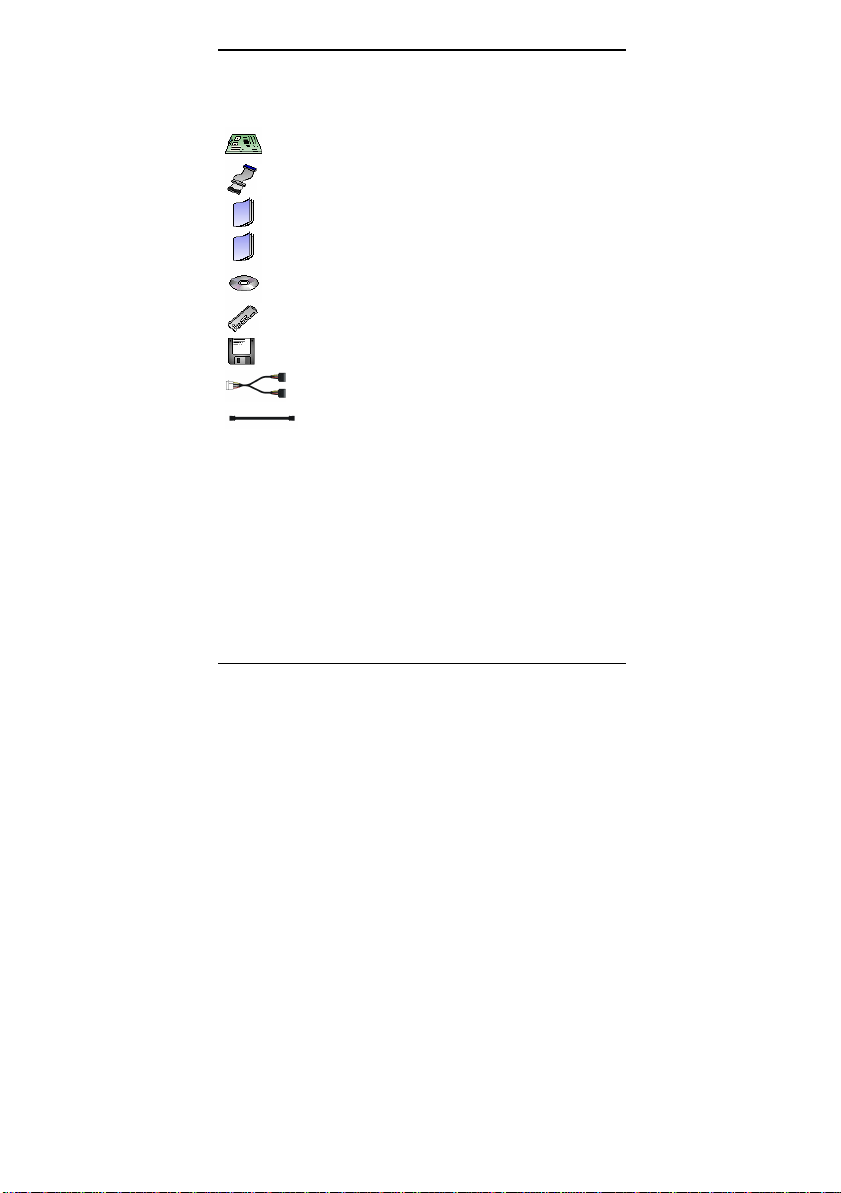
Check the box contents!
The retail motherboard package should contain the following:
1x Thunder i7522 S5362 motherboard
1x 80-pin Ultra-DMA- 133/ 100/66/33 IDE cable
1x Thunder i7522 S5362 User’s Manual
1x Thunder i7522 S5362 Quick Reference
1x TYAN Driver CD
1x I/O shield
1 x Serial ATA driver diskette
1 x Serial ATA power cable
2 x Serial ATA cable s
If any of these items are missing, please contact your vendor/dealer for replacement before
continuing with the installation process.
iii
http://www.tyan.com

Thunder i7522 S5362 Chapter 1: Introduction
Chapter 1: Introduction
1.1 – Congratulations!
You have purchased one of the most powerful Intel Xeon-based server solutions in an
Extended ATX form factor.
Thunder i7522 S5362 is ideal for a pedestal or tower enterprise server systems featuring
some state-of-the-art technologies such as dual/single 800 MHz FSB Xeon processor
support with Xeon dual-core processor, EM64T 64-bit technology, multiple PCI -X buses, PCI Express bus, dual channel DDR2-400 Registered ECC memory design, onboard PCI -Express
Gigabit Ethernet ports, Serial-ATA IDE ports, and multiple USB2.0 (Universal Serial Bus)
ports.
RoHS Compliant
Starting from July 1 2006, the European Union (E.U.) will ban the use of four metals and t wo
flame-retardants in electronic products sold in Europe. This requirement has been set into law
the Restriction of the Use of Certain Hazardous Substances in Electrical and Electronic
Equipment (RoHS) Directive. Other governments are now following Europe’s lead and
enacting the similar legislation.
Tyan also provides Thunder i7522 S5362 RoHS-compliant version to meet EU’s year 2006
standard, today.
Visit Tyan’s website at http://www.tyan.com. There, you can find information on all of Tyan’s
product FAQ’s, lists of worldwide distributors, Tyan software utilities, the latest Windows and
Linux based drivers, memory compatibility listings and much more.
1
http://www.tyan.com

Thunder i7522 S5362 Chapter 1: Introduction
1.2 – i7522 S5362 Hardware Specifications
Processors
- Dual Intel
- Two ZIF mPGA604 sockets
- Onboard EVRD 10.1
- 800 MHz FSB support
- Supports Intel Extended Memory 64
Expansion Slots
- Three PCI -X 133/100/66 MHz slots
- One PCI -X 100/66 MHz slot
- One (x 8) PCI-Express slot with PCI-E
- One 32-bit/33 MHz 3.3-Volts PCI 2.2 slot
- Four PCI -X, one PCI -Express (x 4), and
- Total six usable slots
Chipset
- Intel E7520 system core-logic chipsets
- Winbond W83627HF Super I/O chip
Memory
- Eight DDR2-400 DIMM sockets
- Up to 16 GB of Registered DDR2-400
- Supports Registered ECC type memory
Integrated IDE (Parallel ATA)
- Provides two PCI bus master channels
- Support for UDMA 33/66/100 IDE and
Integrated Serial ATA (SATA) Host
Controllers
- Data transfer rates up to 1.5GB/s
- Supports RAID 0 or 1 (with
- With Adaptec’s driver and option ROM
X eon “Nocona”, “Irwindale”,
“Paxville-DP” processors
Technology (EM64T)
x4 signals
one PCI independent buses
§ E7520 Memory Controller Hub
§ 82801ER (ICH5R) I/O Controller
Hub
§ Two Intel 6700PXH 64 -bit PCI
Hubs
modules
for up to four UDMA IDE devices
ATAPI devices
82801ER/ICH5R chip)
Integrated I/O
- One floppy connector for up to two
drives
- Two 9-pin UART serial support (1
port via cable---optional)
- One 25-pin ECP/EPP parallel
header
- PS/2 mouse & keyboard stacked
connectors
- Six USB 2.0 ports (2 rear USB
connectors, four front USB ports via
optional cables)
BIOS
- Phoenix BIOS 8 Mb flash ROM
- Supports ACPI Power Management:
S1, S3, S4 and S5 modes
- Auto detection of memory size
- Auto configuration of IDE hard disk
types
- User settings of hardware
monitoring
- Multiple boot options including PXE
- Supports Console Redirect
Form Factor
- Extended ATX (12" x 13”)
- One EPS ATX/12V 24- pin system
power connector
- One SSI EEB v3.51 complaint 8-pin
split CPU power connector
- Stacked PS/2 mouse/k eyboard ports
- Stacked four rear USB2.0 ports
- One serial and one VGA ports
- Two side-by-side RJ45 connectors
System Management
- ADI ADT7468 H/W Monitor IC
- Three 4-pin (3-pin compatible) fan
connectors
- Six 3-pin system fan headers
- Tachometer monitoring and PWM
control for certain fans
- One 2-pin chassis intrusion header
- SMBus connectors
2
http://www.tyan.com

Thunder i7522 S5362 Chapter 1: Introduction
Integrated PCI Graphics
- ATI ES1000 PCI controller
- 32 MB DDR memory Frame Buffer
Integrated Two GbE LAN Controllers
- Two Broadcom BCM5721 NICs
- PCI-Express 10/100/1000 GbE LANs
- Two side-by-side RJ45 connectors with
LED’s
TM
TARO
64-bit PCI -X Expansi on Socket
- Tyan proprietary 200 -pin SODIMM
socket
- Operates at 64-bit PCI-X bus
- Supports Intel RAIDIOS and Adaptec
ZCR on the second 64 -bit PCI -X slot
(J41) with an optional M7902/M7901
SCSI TAROTM card or M8110/M8120
SATA TAROTM card
Visit http://www.tyan.com for TAROTM card
support
* Refer to Section IV for greater PCI bus routing clarification
Software Specifications
OS (Operating System) Support
Microsoft Windows 2003 Enterprise Server 64-bit
Microsoft Windows 2003 (Standard) Server 64-bit
Microsoft Windows 2003 (Enterprise) Server 32- bit
Microsoft Windows XP Professional
Microsoft Windows XP Professional 64-bit
Red Hat Advanced Server 3.0 Updated 4
Red Hat EL 4.0 (64- bit)
Red Hat 9.0
SuSE Professional 9.3/10.0 (64-bit)
SuSE Professional 9.3 (32 -bit)
SuSE Professional 9.3/10.0 (64-bit)
SuSE 9.0 Enterprise Server (64- bit)
Other distributions of Linux pending validation
TYAN reserves the right to add support or discontinue support for an y OS with or
without notice.
- Temperature and voltage monitoring
- Watchdog timer
- Optional Tyan SMDC (Server
management Daughter Card) IPMI
1.5/2.0 via a 2x25 header
Regulation
- RoHS-compliant version available
- FCC Class B (Declaration of
Conformity)
- European Community CE
(Declaration of Conformity)
3
http://www.tyan.com

Thunder i7522 S5362 Chapter 1: Introduction
4
http://www.tyan.com
Thunder i7522 S5362 Chapter 1: Introduction
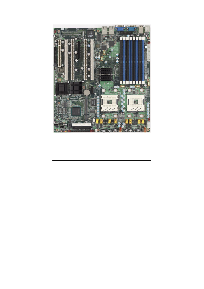
1.3 – i7522 S5362 Board Image
The above picture is purely representative. Due to engineering updates and new board
revisions, certain components may change and or be repositioned. The picture above
may or may not look exactly like the board you received.
5
http://www.tyan.com

Thunder i7522 S5362 Chapter 1: Introduction
1.4 – i7522 S5362 Block Diagram
The following page includes details on the vital components of this motherboard.
6
http://www.tyan.com
Thunder i7522 S5362 Chapter 1: Introduction
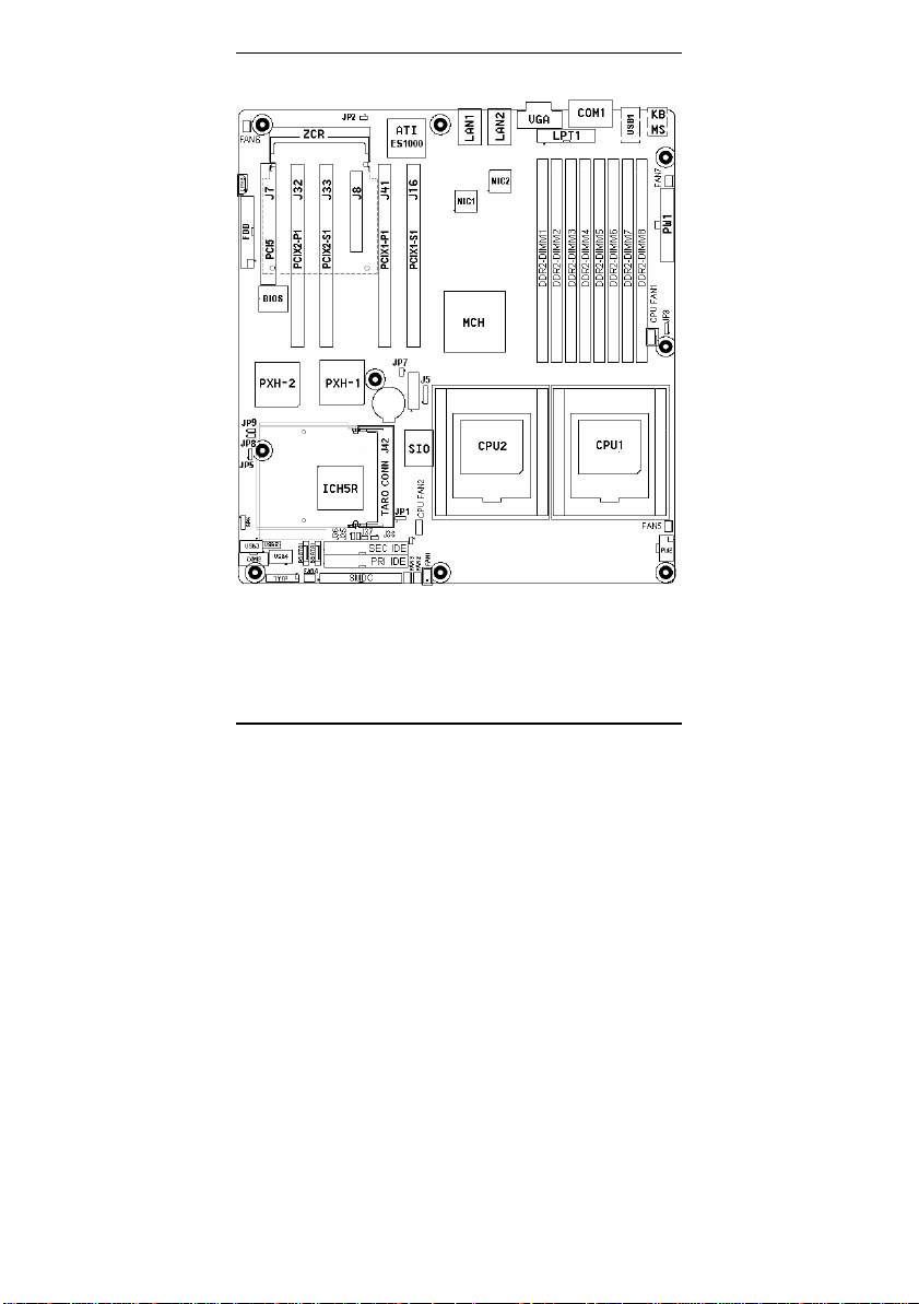
1.5 – i7522 S5362 Components View
Fig. 3-1 Thunder i7522 S5362 Key Component View
This jumper diagram is representative of the latest board revision available at the time
of publishing. The board you receive may or may not look exactly like the above
diagram. The board parts are not to scale.
7
http://www.tyan.com
Thunder i7522 S5362 Chapter 1: Introduction
1.6 – i7522 S5362 Jumper Settings Quick Refer ence
Jumper Function Settings
JP1 CMOS Clear
JP2 Onboard VGA
JP5 Watch-Dog Timer
JP7 PCIX1 Channel B (for PCIX1-
JP8 PCIX2 Channel A (for PCIX2-
JP9 PCIX2 Channel B (for PCIX2-
(Refer to Section 3. 1.2)
(Refer to Section 3. 1.3)
(Refer to Section 3. 1.4)
S1 and PCIX1-S2 slots)
P1 slot)
S1 slot)
SPK Buzzer/External Speaker 1-4: For external speaker connector
CPU
FAN1
CPU
FAN2
FAN1 4-pin System Fan Connector Refer to Section 3. 1.15
FAN2 ~
FAN7
J9 External HDD LED Input
J34 SMDC Connector Refer to Section 3. 1.11
J35, J36 LAN1 LED Header s Refer to Section 3. 1.13
J37, J38 LAN2 LED Header s Refer to Section 3.1.14
USB2 USB Header Refer to Section 3. 1.12
USB3 USB vertical connector Refer to Section 3.1.12
USB4 USB vertical connector Refer to Section 3.1.12
P-SATA/
S-SATA
CPU1 Fan Connector
CPU2 Fan Connector
3-pin System Fan Connectors
Header
SATA Connectors
TYFP (Front Panel Connector)
Signal Pin Pin Signal
HD LED + 1 2 PWR LED +
HD LED - 3 4 GND
GND 5 6 PWR_ONReset Button - 7 8 GND
+5V 9 10 Warning LED+
NC 11 12 GND
3Vsb 13 14 KEY
SMB DATA 15 16 GND
SMB CLK 17 18 Chassis Intrusion-
1-2: Clear CMOS
2-3: Normal
Open: Enable ATI VGA
Close: Disable ATI VGA
1-2: Watchdog Timer (WDT) resets system
2-3: WDT generates NMI
Open: Enable 133 MHz maximum frequency
Close: Disable 133 MHz and up to 100/66 MHz
Refer to Section 3. 1.5
Open: Enable 133 MHz maximum frequency
Close: Disable 133 MHz and up to 100/66 MHz
Refer to Section 3. 1.7
Open: Enable 133 MHz maximum frequency
Close: Disable 133 MHz and up to 100/66 MHz
Refer to Section 3. 1.8
3-4: Enable onboard buzzer
Refer to Section 3. 1.9
Refer to Section 3. 1.15
Refer to Section 3. 1.15
Refer to Section 3. 1.15
Refer to Section 3. 1.10
Refer to Section 3. 1.16
8
http://www.tyan.com

Thunder i7522 S5362 Chapter 2: Choose Proper Parts For Your System
Chapter 2: Choose Proper Parts For Your System
Before you installing a system with this motherboard, make sure your major system parts meet
the following basic guidelines and requirements:
2.1 – Central Processor Unit (CPU) Considerations
§ Process Type and Package
Thunder i7522 S5362 board supports Intel Xeon 800 MHz front side bus (FSB)
processors in 604- pin Pin Grid Array package. Low- voltage Xeon and 2MB L2
cache 800MHz FSB Xeon processors are also supported.
§ Front Side Bus (FSB)
The processor host bus, Front Side Bus (FSB), always operates at 800 MHz.
Choose Intel Xeon 800 MHz FSB processors for Thunder i7522 S5362 board. The
system will not be operational, if you install Intel Xeon 533 or 400 MHz FSB
processors.
§ Single/Dual Processor System
The Thunder i7522 S5362 board supports singl e or dual Intel Xeon 800 MHz FSB
processors.
Single Processor System:
The processor must be installed on the CPU1 ZIF (Zero -Insertion -Force) socket, if
only one processor is present.
Dual Processor System:
For dual processor configurations, both process ors must operate with the same core
frequency, and have the same internal cache sizes. Mixing processors operating at
different FSB frequency, core frequency, core voltage, or cache sizes may cause
system non-operation or damages on processors and/or the m otherboard.
2.2 – Memory Considerations
§ Memory Type
Thunder i7522 S5362 board supports up to eight 184-pin DDR-II 400 Registered
ECC DIMM modules. The DDR-II memory modules can be 256Mb, 512Mb and 1Gb
memory chips. Unbuffered or DDR-I memory modules are not supported.
Visit Tyan’s web site for the memory recommendation list at: www.tyan.com
§ Memory Installation
Thunder i7522 S5362 is based on Intel’s E7520 Lindenhurst chipset. The Intel
E7520 Memory Control Hub (MCH) s upports 144 -bit wide dual memory channels in
interleaved memory scheme, with installing paired memory. With the exception of
Configuration 1 in the memory configuration table below, memory modules are
installed in pairs, starting from DIMM8 towards DIMM1.
Each pair of memory modules must be in the same capacity, density, speed, and
configuration.
DIMM 8
(Black) (Blue) (Black) (Blue)
Conf. 1 X
Conf. 2 X X
Conf. 3 X X X X
Conf. 4 X X X X X X
Conf. 5 X X X X X X X X
Ch. B
DIMM 7
Ch. A
DIMM 6
DIMM 5
Ch. B
Ch. A
9
http://www.tyan.com
DIMM 4
Ch. B
DIMM 3
Ch. A
DIMM 2
Ch. B
DIMM 1
Ch. A
Thunder i7522 S5362 Chapter 2: Choose Proper Parts For Your System
2.3 – Chassis/Enclosure Considerations
§ Motherboard size
The printed circuit board size is 13” (W) x12” (L).
§ Motherboard and CPU Heat-sink Mounting Holes
There are nine motherboard-mounting holes and eight CPU heat -sink mounting
holes on this board design. The motherboard and CPU mounting hole pattern
follows SSI EEB v3.51 (A Server System Infrastructure specification for Entry
Pedestal Servers and Workstations) specifications. Ensure that your chassis
supports those 9 motherboard-mounting holes to secure the motherboard.
Thunder i7522/S5362 supports Intel’s CEK ( Common Enabling Kit ) for securing
Intel’s Xeon 800 MHz FSB processors and processor cooling kits in the chassis.
Two CEK springs for the dual processors are pre - assembled with the motherboard
or enclosed in the motherboard accessory package. The CPU heat -sinks must be
mounted down to the chassis base pan with stand -offs. Any additional chassis
standoffs, besides the 9 motherboard- mounting holes and 8 CPU heat -sink
mounting holes, should be removed to preventing from short -circuit or motherboard
damage.
§ Others
As a system integrator, the air-flow/thermal, EMI/EMC, shock/vibration, and system
packing should be also considered for choosing a proper enclosure.
2.4 – Power Supply Considerations
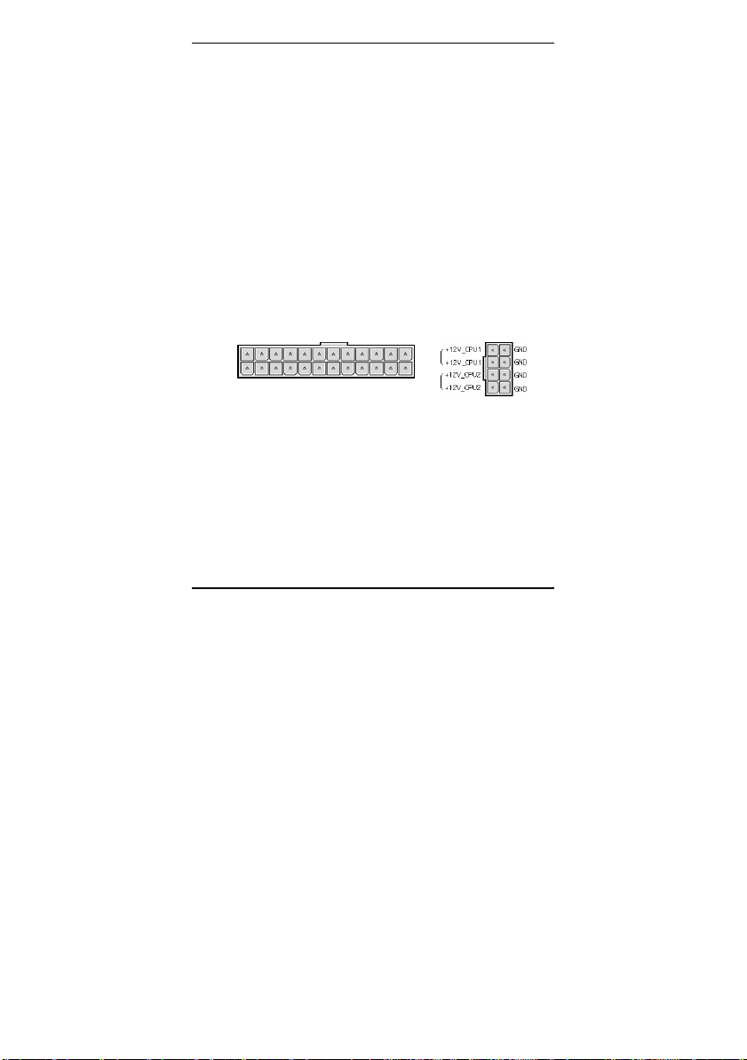
§ Power connectors
The Thunder i7522 S5362 board supports EPS/12V power supply unit (PSU) with
two power connectors listed below.
EPS/12V Power Connectors
24-pin system power connector
(PW1)
§ Split processor power planes
Thunder i7522 S5362 board supports dual Intel’s 800 MHz FSB Xeon processors,
which could reach up to 140 Watts per processor. (Check Intel’s web for your
processor specifications.) By following SSI EEB v3.51 specifications, Thunder
i7522/S5362 is designed with two separate voltage regulator circuits to provide the
power for both onboard processors in separate power rail. Using a power supply
with a combined CPU power plane from the CPU power connector, is not allowed
and may cause system failed to power up or a damage to power supply.
+
8-pin CPU power connector
(PW2)
10
http://www.tyan.com

Thunder i7522 S5362 Chapter 2: Choose Proper Parts For Your System
§ Power requirements
Check your power supply specifications to ensure sufficient power currents for each
power rail based on your system configuration.
The major system components/parts power sources are listed below as reference:
Components/Parts Main Power Source Power Connectors
CPU1 +12V_CPU1 8-pin CPU power connector
CPU2 +12V_CPU2 8-pin CPU power connector
Memory (Normal) +5V 24-pin power connector
Memory
(Suspend to RAM)
System logic +3.3V 24-pin power connector
X8 PCI -Express +12V and +3.3V 24-pin power connector
X1 PCI -Express +12V and +3.3V 24- pin power connector
64-bit PCI -X +12V, +5V, +3.3V and
32-bit PCI +12V, +5V and +3.3V 24-pin power connector
Cooling fans +12V 24- pin power connector
IDE/SATA hard drives +12V and +5V From PSU
CDROM/DVD drives +12V and +5V From PSU
Visit Tyan’s web site for the power supply recommendation list at: www.tyan.com
+5Vstandby 24- pin power connector
3.3Vstandby
24-pin power connector
11
http://www.tyan.com

Thunder i7520 / Thunder i7520R Chapter 3: Board Installation
Chapter 3: Board Installation
How to install our products right…. the first time!
The first thing you should do read this user’s manual. It contains important information that
will make configuration and setup much easier. Here are some precautions you should take
when installing your motherboard:
(1) Ground yourself properly before removing your motherboard from the antistatic bag.
Unplug the power from your computer power supply and then touch a safely
grounded object to release static charge (i.e. power supply case). For the safest
conditions, TYAN recommends wearing a static safety wrist strap.
(2) Inspect the mounting holes pattern of the Thunder i7522 S5362 to match your
chassis standoff locations and remove the additional standoffs.
(3) Hold the motherboard by its edges and do not touch the bottom of the board, or flex
the board in any way.
(4) Avoid touching the motherboard components, IC chips, conn ectors, memory
modules and leads.
(5) Place the motherboard on a grounded antistatic surface or on the antistatic bag that
the board was shipped in.
(6) Inspect the board for damage.
(7) Check the jumper settings and connector locations as described in next sections.
In last sections of this chapter, we will cover the details on how to install your motherboard into
your chassis, as well as installing the processor, memory, disk drives and cables.
Note: DO NOT APPLY POWER TO THE BOARD IF IT HAS BEEN DAMAGED
12
http://www.tyan.com
Thunder i7520 / Thunder i7520R Chapter 3: Board Installation
3.1 – Jumpers
Jumper Example:
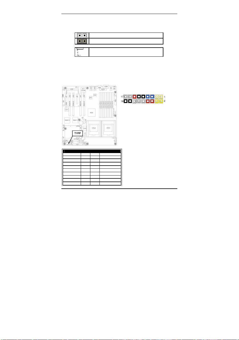
3.1.1 - Front Panel Header (TYFP)
Normally, a chassis has some control or signal wires can be connected ont o a motherboard
for hard drive LED, power LED, power button, and reset button,
The front panel header (m arked as “TYFP ”) has been implemented on a Thunder i7522 S5362
board for such purposes.
OPEN - Jumper OFF Without jumper cover
CLOSED - Jumper ON With jumper cover
To indicate the location of pin-1
Front Panel Header (TYFP )
TYFP (Front Panel Connector)
Signal Pin Pin Signal
HD LED + 1 2 PWR LED +
HD LED - 3 4 GND
GND 5 6 PWR_ONReset Button - 7 8 GND
+5V 9 10 Warning LED+
NC 11 12 GND
3Vsb 13 14 KEY
SMB DATA 15 16 GND
SMB CLK 17 18 Chassis Intrusion-
http://www.tyan.com
13

Thunder i7520 / Thunder i7520R Chapter 3: Board Installation
You can reset the CMOS settings by pressing
this button, if you have forgotten your
system/setup password or need to clear
Place the jumper shunt to close
JP1 Pin 1 and Pin 2 for several
Move the jumper shunt back to JP1
The onboard ATI ES1000 graphics controller
bit 33 MHz PCI bus with 32
3.1.2 - Clear CMOS (JP1)
system BIOS settings.
3.1.3 - Enable/Disable onboard ATI ES1000 graphics (JP2)
is placed on 32MB video frame buffer.
14
http://www.tyan.com
JP1
Pin 1-2: Clear CMOS
Pin 2-3: Normal (Default)
- Power off system and disconnect
both power connectors f rom
the motherboard
-
seconds to Clear CMOS
Pin 2 and Pin 3 position
JP2
OPEN: Enable Onboard VGA
(Default)
CLOSED: Disable Onboard VGA
Thunder i7520 / Thunder i7520R Chapter 3: Board Installation
Once the watchdog function is enabled in
BIOS setup, system needs an application or
utility to clear the watchdog timer periodically
before the timer expiration. If the application
atchdog timer, the
system will be reset or entered a NMI service
It is an OEM option of generating NMI service
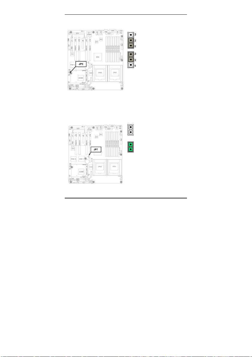
3.1.4 – Watch dog Timer (JP5)
3.1.5 – PCIX -1 Channel B (for PCIX1-S1 and PCIX1 -S2 slots) Maximum Freq uency (JP7)
http://www.tyan.com
JP5
Pin 1-2: Watchdog resets system
(Default)
Pin 2-3: Watchdog generates NMI
or utility fails to clear the w
routine, depending on the JP5 setting.
routing for watchdog function.
JP7
OPEN: 133/100/66 MHz
(Default)
CLOSE: 100/66 MHz
JP7 is for onboard PXH- 1 Channel B PCI -X
bus frequency setting.
The PCIX1 -S1 and PCIX1 -S2 slots are the
only devices on this PCI -X bus.
Only one device/add-in card on PCIX1 -S1
slot is allowed to run this bus to run PCI -X
frequency up to 133 MHz. Placing two or
more devices on PCIX1-S1 through a riser
card or installing one device on PCIX1- S2
slot can only support up to PCI -X 100 MHz.
15
Thunder i7520 / Thunder i7520R Chapter 3: Board Installation
3.1.6 – PCIX -1 Channel A Maximum F requency
The following devices are connected to PCIX- 1 Channel A PCI - X bus:
- TARO Socket (Tyan’s 200-pin SODIMM proprietary socket)
- PCIX1-P1 64-bit PCI-X slot (available on Thunder i7522 S5362 only)
- ZCR socket (Reserved)
The maximum PCI -X bus frequency on this bus (PCIX- 1 Channel A) is set to 100/66MHz.
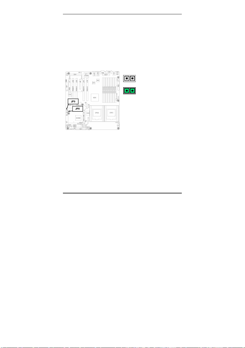
3.1.7 – PCIX -2 Channel A Maximum F requency
JP8 (For PCIX2- P1 PCI -X slot)
OPEN: 133/100/66 MHz
(Default)
CLOSE: 100/66 MHz
JP8 is for the onboard secondary PXH I/O
Bridge chip (PXH -2) Channel A PCI -X bus
frequency setting.
The PCIX2 -P1 slot is the only device on this
PCI-X bus.
16
http://www.tyan.com
 Loading...