

Tyan THUNDER GC-HE User Manual

S4520 THUNDER GC-HE
Revision 1.01
Copyright © TYAN Computer Corporation, 2002. All rights reserved. No part of this manual may be
reproduced or translated without prior written consent from TYAN Computer Corp.
All registered and unregistered trademarks and company names contained in this manual are
property of their respective owners including, but not limited to the following.
TYAN, Thunder GC-HE S4520 are trademarks of TYAN Computer Corporation.
Adaptec is a trademark of Adaptec Inc.
IBM, PC, AT, PS/2 are trademarks of IBM Corporation.
Intel, Xeon, and combinations thereof are trademarks of Intel Corporation.
Microsoft, Windows are trademarks of Microsoft Corporation.
Phoenix is a trademark of Phoenix Technologies.
QLogic, Zircon, and combinations thereof are trademarks of QLogic Corporation.
ServerWorks, Grand Champion, and combinations thereof are trademarks of ServerWorks, Inc.
Winbond is a trademark of Winbond Electronics Corporation.
Information contained in this document is furnished by TYAN Computer Corporation and has been
reviewed for accuracy and reliability prior to printing. TYAN assumes no liability whatsoever, and
disclaims any express or implied warranty, relating to sale and/or use of TYAN products including
liability or warranties relating to fitness for a particular purpose or merchantability. TYAN retains the
right to make changes to product descriptions and/or specifications at any time, without notice. In
no event will TYAN be held liable for any direct or indirect, incidental or consequential damage,
loss of use, loss of data or other malady resulting from errors or inaccuracies of information
contained in this document.
1
http://www.tyan.com

Before you begin…
Chapter 1: Introduction
1.1 Congratulations
1.2 Hardware Specifications
Chapter 2: Board Installation
2.0 Board
2.1 Jumper Definitions
2.2 PCI Hot-Plug
2.3 PCI Setup
2.4 Mounting the Motherboard
2.5 Processors and Frequency Settings
2.6 Installing the Processors/Heatsinks
2.7 Installing the VRMs
2.8 Installing the Memory
2.9 Memory Pair Installation
2.10 Attaching Drive Cables
2.11 Installing Add-In Cards
2.12 Connecting External Devices
2.13 Installing the Power Supply
2.14 Finishing Up
Chapter 3: BIOS Setup
3.0 BIOS Setup Utility
3.1 BIOS Menu Bar
3.2 BIOS Legend Bar
3.3 BIOS Main Menu
3.4 BIOS Advanced Menu
3.5 BIOS Security M enu
3.6 BIOS Boot Menu
3.7 BIOS Exit Menu
Chapter 4: Diagnostics
4.1 Beep Codes
4.2 Flash Utility
Glossary
Technical Support
Appendix
Table of Contents
.……………………………………………..Page 3
.……………………………………………..Page 4
.……………………………………………..Page 4
.……………………………………………..Page 4
.……………………………………………..Page 7
.……………………………………………..Page 8
.……………………………………….Page 9 - 13
…..…………………………………..Page 14 - 15
..…………………………………………..Page 16
..…………………………………………..Page 17
………………………………………Page 18
..…………………………………….Page 19 - 21
..…………………………………………..Page 22
..……………………………………..Page 23 - 24
..……………………………………..Page 25 - 26
..……………………………………..Page 27 - 28
..…………………………………………..Page 29
..…………………………………………..Page 30
..……………………………………..Page 31 - 32
..…………………………………………..Page 33
..…………………………………………..Page 34
..…………………………………………..Page 34
..…………………………………………..Page 35
..…………………………………………..Page 35
..…………………………………………..Page 36
..…………………………………………..Page 37
..…………………………………………..Page 41
..…………………………………………..Page 41
..…………………………………………..Page 42
..…………………………………………..Page 43
..…………………………………………..Page 43
..…………………………………………..Page 43
..……………………………………..Page 44 - 48
..…………………………………………..Page 49
..…………………………………………..Page 50
2
http://www.tyan.com
Before you begin…
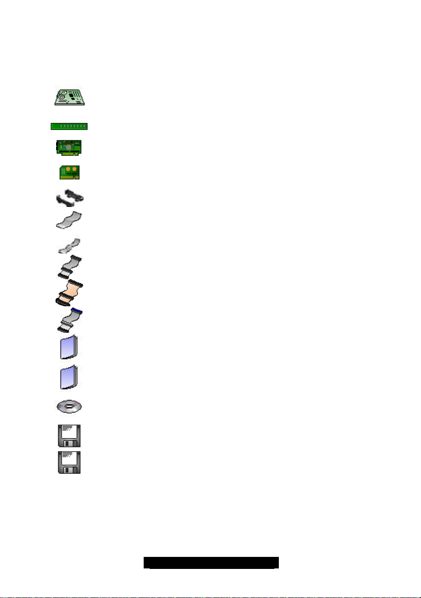
Check the box contents!
The retail motherboard package should contain the following:
If any of these items are missing, please contact your vendor/dealer for replacement before
continuing with the installation process.
1x Thunder GC-HE motherboard
1x Hot-plug switch panel
1x Tyan M3288 SMDC
4x CPU VRMs (Voltage Regulator Module)
4x CPU retentions
2x flat ribbon cables
1x ribbon cable for hot-plug control panel
1x 34-Pin floppy drive cable
1x Ultra160 LVD SCSI cable
1x Ultra-DMA-100/66/33 IDE cable
1x Thunder GC-HE User’s Manual
1x Thunder GC-HE Quick Reference Guide
1x TYAN driver CD
1x Adaptec Ultra160 SCSI driver diskette
1x SMDC and TSO drivers
3
http://www.tyan.com

Chapter 1: Introduction
1.1 – Congratulations!
Thank you for choosing the TYAN Thunder GC-HE, the ultimate 4-way XEON platform designed
for high-performance, mission critical and data intensive applications. This board is designed to
accommodate the needs of users who require minimal down-town and the most flexibility. Special
features of this board are: PCI-X hot-plug support, dual 10/100 Ethernet ports, dual-channel
Ultra160 SCSI and onboard video.
Remember to visit TYAN’s Website at http://www.tyan.com. There you can find information on all
of TYAN’s products with FAQs, distributors list and BIOS setting explanations.
1.2 – Hardware Specifications
Processor
• Quad mPGA603 ZIF sockets
• Supports up to 4 Intel XEON MP processors
or up to 2 XEON DP processors
• Four VRM 9.1 current share sockets
• Source synchronous bus of 200MHz
• Front-Side Bus support for 400MHz
Chipset
• ServerWorks Grand Champion HE chipset
• ServerWorks CMIC host bridge
• ServerWorks CIOB-X 3.0 I/O bridges (two)
• ServerWorks CSB5 south bridge
• National NS87417 Super I/O ASIC
Memory
• Memory Expansion Card (MEC) design with
twelve 2.5V 184-pin DDR DIMM sockets
• Supports up to 24GB of Registered DDR
RAM
• Multi-bit memory ECC
Expansion Slots
• Seven 64-bit 100MHz (3.3V) PCI-X slots
• Each CIOB-X supports two PCI-X buses with
up to two PCI-X slots on each bus
• One 32-bit 33MHz (5V) PCI slot
• Total of eight usable slots
Integrated SCSI (manufacturing option)
• Adaptec AIC – 7899W controller
• Dual Channel Ultra160 SCSI support
• 160MB/sec per channel; 15 LVD devices per
channel
• Channel A and Channel B – 68-pin
connectors
Integrated 2D/3D Graphics
• ATI RAGE XL graphics controller
• 4MB frame buffer
• Standard 15-pin analog VGA port
Integrated LAN
• Two Intel 82550 LAN controllers (with TCO)
• 10/100Mbps data transfer rate per controller
• Supports WOR (Wake on Ring) and WOL
(Wake on LAN)
Server Management (daughter card option)
• Tyan Server Management Connector, 50-pin
• QLogic Zircon Baseboard Management
Controller (BMC)
• Supports the Intelligent Platform Management
Interface (IPMI)
• Two I2C private buses, EMP, and fault
resilient booting
BIOS
• Phoenix BIOS on 4Mbit Flash ROM
• Supports APM v1.2 and ACPI v1.0
• User settings for hardware monitoring
• Auto-configuration of IDE hard drive types
• Multiple boot options
• DMI 2.0 compliant, console redirection
Integrated PCI IDE
• Dual Channel master mode
• Supports up to four Enhanced IDE devices
• Support for ATA-100/66/33 IDE and ATAPI
compliant devices
4
http://www.tyan.com

Integrated I/O
• One floppy connector supports up to two
drives
• Two 9-pin 16550-based serial ports
• One 25-pin SPP/ECP/EPP parallel port
• Two USB 1.1 ports
• PS/2 keyboard and mouse ports
Software Support
Windows NT 4 Server
Windows 2000 family
Windows XP family
RedHat Linux 7.3
TYAN reserves the right to add support or
discontinue support for any OS with or
without notice.
Form Factor
• SSI MEB footprint
(16" x 13", 406.40mm x 330.20mm)
• Compatible with 4U height restriction if rack
mounted
• Application-specific power connector suite;
adapter included for compatibility with EPS12V
power supply
• Stacked parallel (one), serial (two) and VGA
(one) ports
• Side-by-side LAN ports (two)
• Stacked USB ports (two)
• Stacked keyboard and mouse ports
Regulatory
• FCC Class B certified
(Declaration of Conformity)
• European CE certified
(Declaration of Conformity)
5
http://www.tyan.com

6
http://www.tyan.com

Chapter 2: Board Installation
Installation
You are now ready to install your motherboard. The mounting hole pattern of the Thunder GC-HE
matches the SSI MEB specification. Before continuing with installation, confirm that your chassis
supports a standard SSI MEB motherboard.
How to install our products right….the first time!
The first thing you should do is read this user’s manual. It contains important information that will
make configuration and setup much easier. Here are some precautions you should take when
installing your motherboard:
(1) Ground yourself properly before removing your motherboard from the antistatic bag.
Unplug the power from your computer power supply and then touch a safely grounded
object to release static charge (i.e. power supply case). For the safest conditions, Tyan
recommends wearing a static safety wrist strap.
(2) Hold the motherboard by its edges and do not touch the bottom of the board, or flex the
board in any way.
(3) Avoid touching the motherboard components, IC chips, connectors, memory modules,
and leads.
(4) Place the motherboard on a grounded antistatic surface or on the antistatic bag that the
board was shipped in.
(5) Inspect the board for damage.
The following pages include details on how to install your motherboard into your chassis, as well
as installing the processor, memory, disk drives and cables.
NOTE DO NOT APPLY POWER TO THE BOARD IF IT HAS BEEN DAMAGED
7
http://www.tyan.com
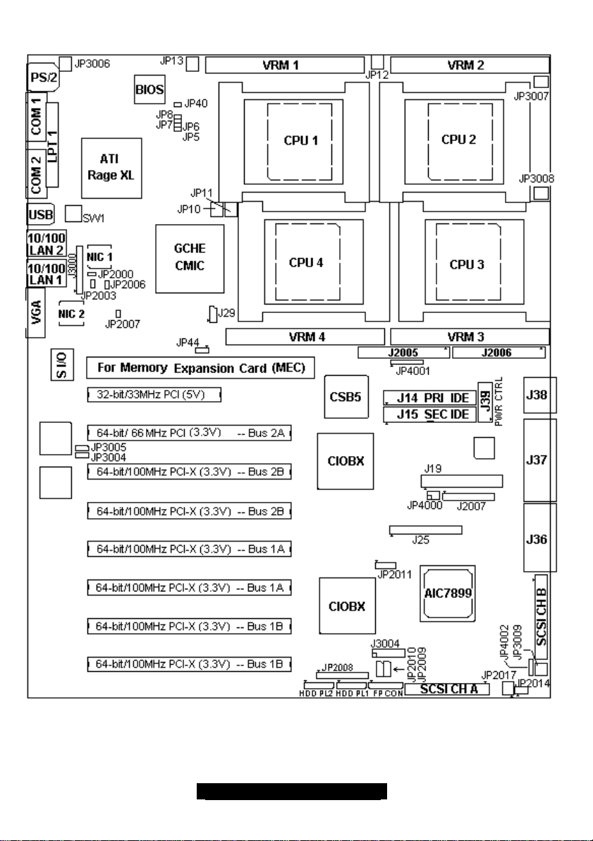
2.0 – Board
Your board may or may not look exactly like the above diagram due to the loading options.
IMPORTANT NOTE:
Fan locations as labeled on some revisions of the motherboard may be incorrect. It is highly
recommended if you intend to monitor fans, that you use the information in this manual for accuracy. If
you found the addendum in your package you absolutely will need to follow the manual for accurate
location and function of fan headers.
8
http://www.tyan.com

2.1 – Jumper Definitions
Jumper
Number
JP5 Clock Spread Spectrum Enabled/Disabled.
JP7 Clock swing Select 1.
JP8 Clock swing Select 0.
J25 Front Panel Connector Page 12
J29 SMBUS 3-pin 5V connector (N/A)
JP2000 Onboard SCSI Page 9
JP2003 Onboard ATI RAGE XL Page 9
JP2006 Onboard LAN 1 Page 9
JP2007 Onboard LAN 2 Page 9
JP2009 IPMI 3-pin 5V AUX Power connector (N/A)
JP2010 IPMI 3-pin 5V AUX Power connector (N/A)
JP2011 BMC local bus 4-pin 5V AUX Power connector (N/A)
J3000 Hot plug control cable connector Page 14
JP3004 Hot Plug for PCI-X Bus 1 Page 9
JP3005 Hot Plug for PCI-X Bus 2 Page 10
JP4000 CMOS Reset Page 11
Description Reference
Page
(N/A)
This option should be disabled when using a TYAN FCC tested and
approved chassis. The option to enable has been retained for
alternate chassis use in order to pass FCC testing. Spread
spectrum clocking should be disabled (OFF) whenever possible.
ON = Spread Spectrum enabled
OFF = Spread Spectrum disabled
Default = OFF
(N/A)
Use this setting to adjust the CPU clock swing. This setting can also
be used to during FCC testing. However, any setting other than the
TYAN defaults should be extensively tested by a certified technician
prior to use.
Default = OFF
Set for 6x IREF
(N/A)
Use this setting to adjust the CPU clock swing. This setting can also
be used to during FCC testing. However, any setting other than the
TYAN default should be extensively tested by a certified technician
prior to use.
Default = ON
Set for 6X IREF
9
http://www.tyan.com

Jumper Definitions Cont.
Jumper Number Description Reference Page
JP44
* Note. Jumper has
to be set 1-2 at boot
up time for BIOS to
size the memory and
complete POST.
JP3009 Speaker connector Pin 1 = Speaker + (near mounting hole)
JP4002 Optional (additional) front
Pin 1-2 Normal position.
South bridge is master on
SMBUS.
Pin 2-3 Debug position.
South bridge slave registers
can be dumped on SMBUS.
panel connector when using
the TYAN SMDC baseboard
management controller
BMC. Switches and error
status are controlled directly
by the BMC.
*Pins also require a TYAN
supported IPMI/ SAF-TE
SCSI back plane.
(NA)
Pin 2 = NC
Pin 3 = NC
Pin 4 = Speaker – ( Ground)
See page 10
Pin 1 = Buzzer stop BTN+
Pin 2 = Buzzer stop BTNPin 3 = System Power led +
Pin 4 = System Power led –
*Pin 5 = Hard drive platter activity led +
*Pin 6 = Hard drive platter activity led –
Pin 7 = Error led +
Pin 8 = Error led –
*Pin 9 = Hard drive error led +
*Pin 10= Hard drive error led –
Pin 11= Fan error led +
Pin 12= Fan error led Pin 13= Power supply error led +
Pin 14= Power supply error led Pin 15= EXT error led +
Pin 16= EXT error led -
10
http://www.tyan.com
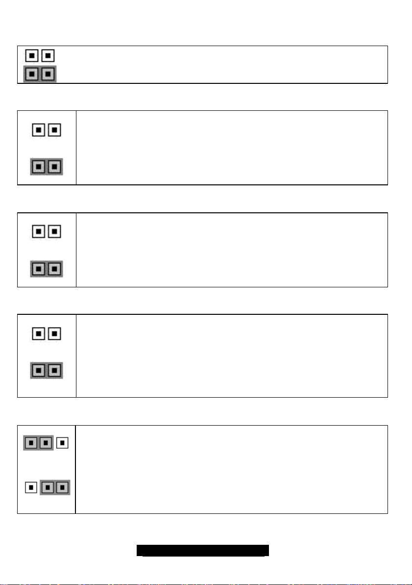
Jumper Definitions – Feature jumpers
Jumper OFF – open (without jumper shunt)
Jumper ON – closed (with jumper shunt)
Onboard SCSI (JP2000)
Onboard ATI RAGE XL (JP2003)
Onboard LAN 1 (JP2006) and LAN 2 (JP2007)
Enabled
Disabled
Enabled
Disabled
Use JP2000 to enable or disable onboard SCSI. This jumper will affect both SCSI
channels A and B.
If enabled, PCI slot 2 will operate at 66MHz. If disabled, PCI slot 2 will operate at
100 MHz.
Use JP2003 to enable or disable onboard graphics controller.
Onboard ATI RAGE XL graphics shares PCI bus with the onboard LAN
controllers.
Enabled
Disabled
Hot Plug for PCI-X Bus 1 (JP3004)
1
Enabled
1
Disabled
Use JP2006 to enable or disable onboard LAN 1.
Use JP2007 to enable or disable onboard LAN 2.
Onboard LAN shares PCI bus with onboard ATI RAGE XL graphics controller.
Use JP3004 to enable or disable Hot Plug functionality on PCI-X slots 5, 6, 7, and 8.
Enabling Hot Plug will allow you to insert and remove 64-bit PCI expansion cards. OS
and chassis support required.
Enabled = Close pins 2 and 3
Disabled = Close 1 and 2
11
http://www.tyan.com
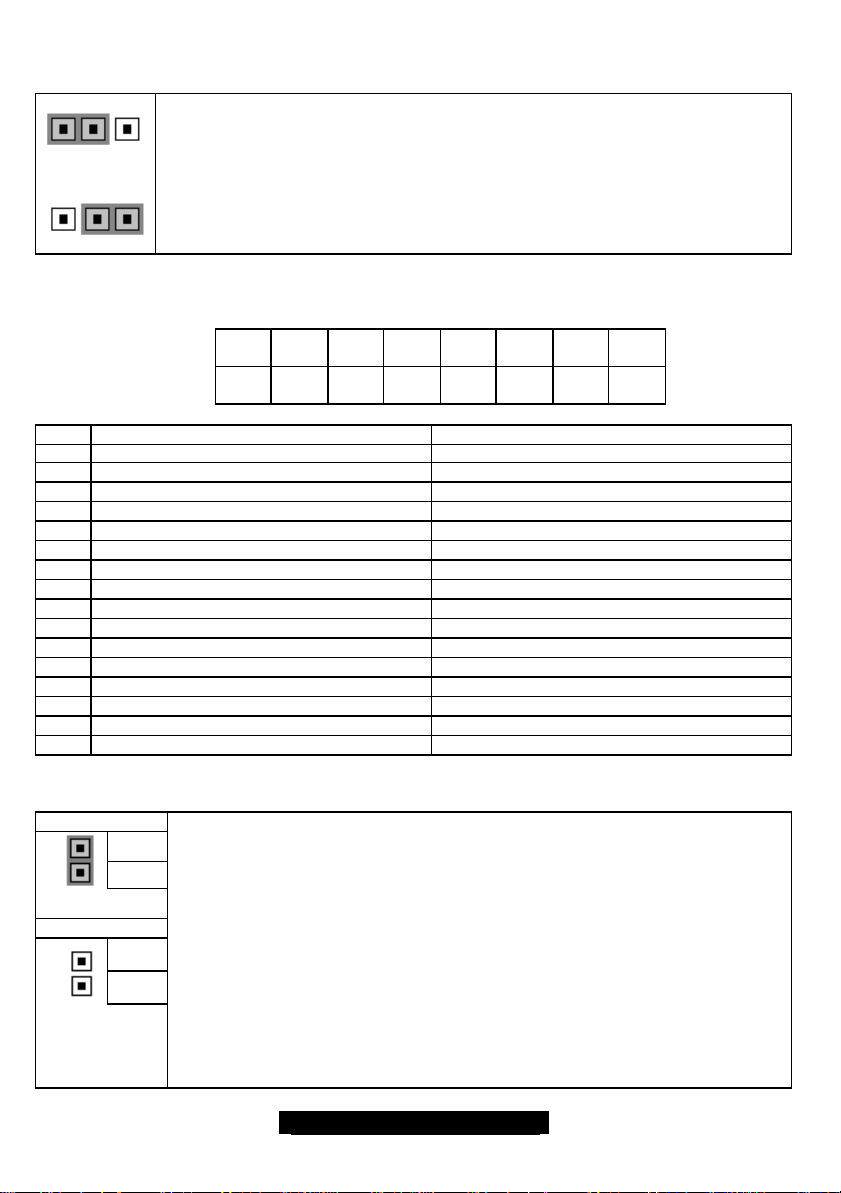
Hot Plug for PCI-X Bus 2 (JP3005)
1
Use JP3005 to enable or disable Hot Plug functionality on PCI-X slots 2, 3, and 4.
Enabling Hot Plug will allow you to insert and remove 64-bit PCI expansion cards. OS
Enabled
1
and chassis support required.
Enabled = Close pins 2 and 3
Disabled = Close 1 and 2
Disabled
SMDC cable connector (J3004)
Pin 2 Pin 4 Pin 6 Pin 8 Pin
Pin 1 Pin 3 Pin 5 Pin 7 Pin 9 Pin
10
Pin
12
11
Pin
14
Pin
13
Pin
16
Pin
15
Pin Signal Definition Front Panel Connection Requirements
1 Buzzer Stop switch + Side A of normally open momentary switch
2 Buzzer Stop switch - Side B of normally open momentary switch
3 BMC controlled power LED + Anode of LED G
4 BMC controlled power LED - Cathode of LED G
5 Back plane Hard drive ACT + Anode of LED H
6 Back plane Hard drive ACT - Cathode of LED H
7 ANY BMC reported ERR LED + Anode of LED I
8 ANY BMC reported ERR LED - Cathode of LED I
9 Raid back plane controller error + Anode of LED J
10 Raid back plane controller error - Cathode of LED J
11 ANY system fan error LED + Anode of LED K
12 ANY system fan error LED - Cathode of LED K
13 Any power supply error + Anode of LED L
14 Any power supply error - Cathode of LED L
15 System External error + Anode of LED M
16 System External error - Cathode of LED M
CMOS Reset (J4000)
Clear CMOS
Normal
Pin 5
Pin 6
Pin 5
Pin 6
You can reset the CMOS settings in case an incorrect setting causes system
instability or you have forgotten your system/setup password or have just flashed
your BIOS by using these jumpers.
- Power down the system
- Set jumper J4000 to Clear CMOS by closing pins 5 and 6 with a jumper shunt
- Power up the system
- The system will notify you that the CMOS has a bad checksum . Then, ask you to
press <F2> to reconfigure the CMOS or <F1> to continue to boot up the system
with the default values.
- Press <F2> to enter the CMOS setup and load BIOS optional defaults
- Save the CMOS and exit the CMOS setup.
- Power down system and remove the jumper shunt on Pin 5 & 6.
- The CMOS will be loaded with defaults during the next power-up.
12
http://www.tyan.com
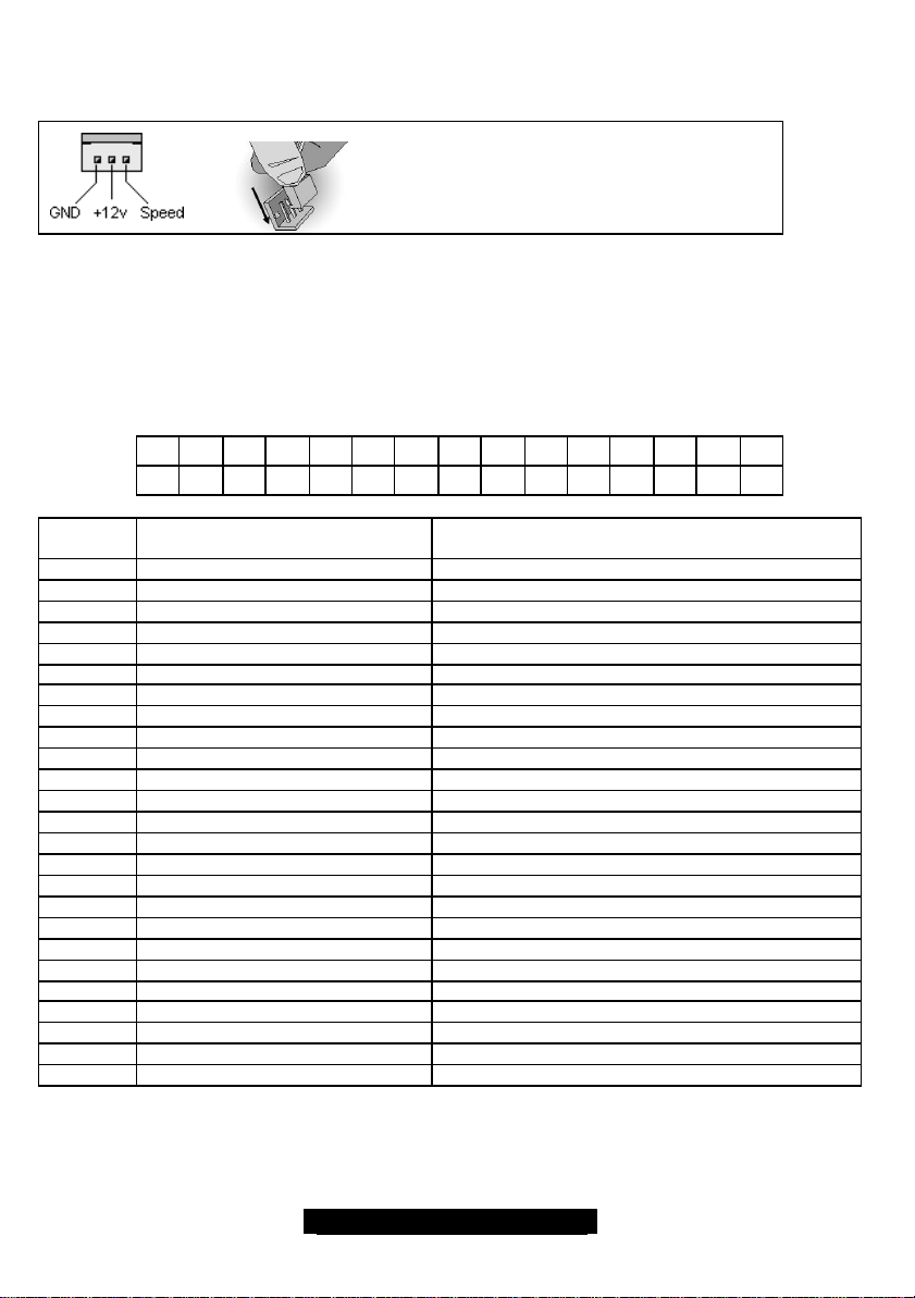
FAN connectors (FAN)
All FAN connectors on this board are hardware monitored.
Front Panel Connector (J25)
The Thunder GC- HE requires that you have the appropriate chassis which supports the features on the
Thunder GC-HE.
J25 Pin-out:
Pin #
1 Reset button + Side A of normally open momentary switch
2 Reset button - Side B of normally open momentary switch
3 Sleep button + Side A of normally open momentary switch
4 Sleep button - Side B of normally open momentary switch
5 System Power button + Side A of normally open momentary switch
6 System Power button - Side B of normally open momentary switch
7 Reserved + Anode of LED A
8 Reserved – Cathode of LED A
9 System Power LED + Blinks in S1 Anode of LED B
10 System Power LED – Blinks in S1 Cathode of LED B
11 Network ACT LED + Anode of LED C
12 Network ACT LED – Cathode of LED C
13 System Fault 1 LED + CPU error Anode of LED D
14 System Fault 1 LED – CPU error Cathode of LED D
15 System Fault 2 LED+ VRM error Anode of LED E
16 System Fault 2 LED – VRM error Cathode of LED E
17 to 22 Reserved
23 Hard drive ACT + Anode of LED F
24 Hard drive ACT - Cathode of LED F
25 User NMI Button + Side A of normally open momentary switch
26 User NMI Button - Side B of normally open momentary switch
27 Intrusion SW 1 + Side A of normally open momentary switch
28 Intrusion SW 1 - Side B of normally open momentary switch
29 Intrusion SW 2 + Side A of normally open momentary switch
30 Intrusion SW 2 - Side A of normally open momentary switch
Jumper Definition Notes – Use this page to record your customized jumper settings for future
reference.
Use these headers to connect cooling fans, both
4 6 8 10 12 14 16 18 20 22 24 26 28
2
1 3 5 7 9 11 13 15 17 19 21 23 25 27 29
Signal Definition Front Panel Connection requirements
chassis and processor fans, to your motherboard.
Cooling fans help keep the system more stable and
operating reliably for its product life.
Support +12V fans
30
13
http://www.tyan.com
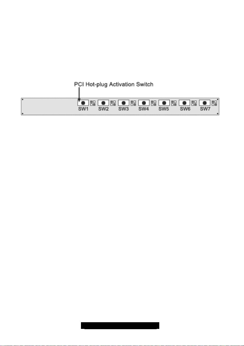
2.2 – PCI Hot-Plug Connector and Switch Module (J3000)
The Thunder GC-HE exclusively features advanced PCI Hot-plug features that will allow the removal and
installation of PCI-(X) cards while the system is operating. This feature requires a compatible chassis and
compatible operating system (OS). The following OSes will support PCI Hot-Plug:
Windows 2000 Advanced Server
Windows XP Professional
To use the PCI Hot-Plug feature, a switch module has been included with your board. This module must
be installed for the Hot-Plug feature to function. A chassis compatible with the module is also required.
Slot Correspondence: Slot2 Slot3 Slot4 Slot5 Slot6 Slot7 Slot8…
LED Indications
On the Hot-Plug panel, there are 7 switches for the 7 64-bit PCI-X/PCI slots (from Slot 2 to Slot 8) and
each switch controls one slot. SW1 controls Slot 2, SW2 controls Slot3, SW3 controls Slot 4, and so on so
forth. Besides the switches, there are two LED lights, in green and orange colors, next to each switch to
indicate the corresponding PCI slot status.
GREEN LED OFF status – this indicates that the specific PCI slot is off or no any card is present.
GREEN LED ON status – this indicates that a card is installed and in operation in the specific PCI slot.
ORANGE LED OFF status – this indicates that the specific PCI slot is functional properly.
ORANGE ON status – this indicates that there is an error on this slot and is usually caused by installing a
PCI card that cannot operate at the PCI slot’s frequency.
ORANGE FLASHING status – this indicates that the slot cannot power on with the card being installed.
Enable it by turning system power off, reinstalling the card, and powering the system back on.
Note:
² The 32-bit/33 MHz PCI slot does not support hot-plug feature.
² S4520 supports PCI-X hot-plug and the default speed is 100MHz , when the bus does not
have any PCI cards installed or is not shared with a slot that has a card at 66 or 33MHz.
Once the system is running you may only hot-plug a card into the system with the same
speed as the PCI bus.
² Slot 2 is always 66MHz. It shares the same PCI bus with onboard SCSI, which is limited to
run at 66MHz.
² Slot 3 and 4 are on the same bus. Short the jumper JP3002, if you want the default bus
speed to be 66MHz in order to add cards with the OS running. Leave JP3002 open, if you
want to run PCI-X 100MHz on this bus.
² Slot 5 and 6 are on the same bus. Short the jumper JP30, if you want the default bus speed
to be 66Mhz in order to add cards with the OS running. Leave JP30 open, if you want to
run PCI-X 100MHz on this bus.
² Slot 7 and 8 are on the same bus. Short the jumper JP3000, if you want the default bus
speed to be 66Mhz in order to add cards with the OS running. Leave JP30 open, if you
want to run PCI-X 100MHz on this bus.
² JP3002, JP30 and JP3000 set the bus frequencies for those buses independently and only
take the effects during the power up or cold reset.
14
http://www.tyan.com
Hot-Plug a PCI card
² Step 1: Ensure the Green LED to be OFF for the PCI slot, which you wish to install/exchange/remove
a PCI card. If there is a PCI card already installed on this PCI slot and the corresponding Green LED
on the Hot-Plug control panel is ON, then press the corresponding slot switch to turn this Green LED
OFF.
² Step 2: Once the Green LED goes OFF, which indicates this PCI slot is OFF and ready for Hot-Plug.
At this moment, you can install, exchange or remove a PCI card. If you install a new PCI card,
ensure that the new PCI card matches the PCI bus speed.
² Step 3: If you install a new PCI card, press the slot switch and wait for the Green LED to turn ON.
Once the Green LED goes ON, this PCI slot will be activated.
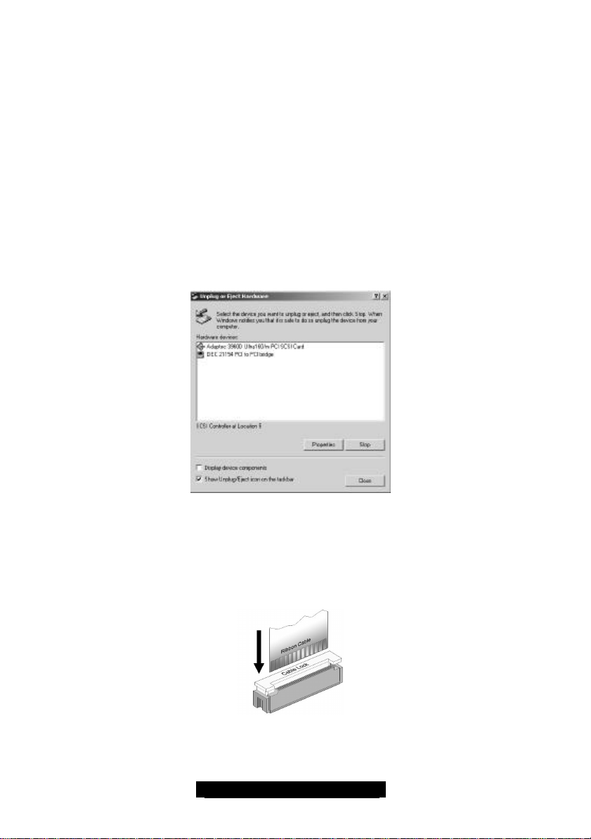
If you are using a hot-plug supported OS, such as Windows 2000 Server, you can utilize the Hot-plug
control features by double clicking on the Unplug or Eject Hardware icons on the task bar. Simply select
the particular PCI device to remove, click the stop button on the pop-up window and lick OK button. The
corresponding Green LED for that PCI slot will be OFF and can safely remove the card on this slot.
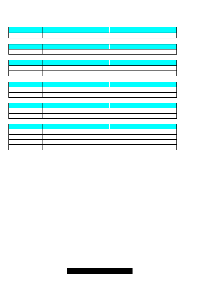
Hot-Plug Cables
A supplied flat ribbon cable will connect the PCI Hot-Plug module (from the rear) to the
motherboard (JP3000). Each switch on the module corresponds to each of the PCI-X slots on the
board.
To install a flat ribbon cable, lift the Cable Lock and then insert the ribbon cable with the connection side
facing away from the Cable Lock. After the cable is firmly inserted, press the Cable Lock back down and
your cable is connected. All flat ribbon cables on the board are installed in the same manner.
15
http://www.tyan.com
2.3 – PCI Setup
Slot # Connector # Type Bus # Device #
1 J16 PCI 32b/33 0 9
Slot # Connector # Type Bus # Device #
2 J10 PCI 64b/66t 7 5
Slot # Connector # Type Bus # Device #
3 J12 PCI-X 100 9 7
4 J11 PCI-X 100 9 8
Slot # Connector # Type Bus # Device #
5* J5 PCI-X 100 1 1
6* J6 PCI-X 100 1 2
Slot # Connector # Type Bus # Device #
7 J8 PCI-X 100 4 3
8 J7 PCI-X 100 4 4
Onboard Connector # Type Bus # Device #
ATI VGA J2000 PCI 32b/33 0 A
SCSI J2001, J2002 PCI 64b/66t 7 9
LAN 1 J2003 PCI 32b/33 0 B
LAN 2 J2004 PCI 32b/33 0 C
*NOTE: Any PCI cards that are intended to wake up the system from Suspend state using the PME#
signal protocol (such as NIC adapters) are required to be installed in PCI slot 5 or PCI slot 6. The default
configuration assumes that the embedded LAN adapter number 1 will provide this function. However, if
you are using a card in PCI slot 5 or PCI slot 6 for this wakeup function then the embedded LAN adapter
should be set in the driver power management section to not allow wake up from this device.
t
NOTE: Slot 2 is shared the same PCI bus with the onboard SCSI controller and only operate at 66MHz
in PCI mode.
16
http://www.tyan.com
 Loading...