

Page 1

Plasma Cutting
Power Supply
CutMaster™ 50
A-02766
Operating Manual
April 21, 2003 Manual No. 0-2805
Page 2

WARNINGS
Read and understand this entire Manual and your employer’s safety practices before installing, operating, or servicing the equipment.
While the information contained in this Manual represents the
Manufacturer's best judgement, the Manufacturer assumes no liability for
its use.
Plasma Cutting Power Supply
CutMaster 50
Operating Manual Number 0-2805
Published by:
Thermal Dynamics Corporation
82 Benning Street
West Lebanon, New Hampshire, USA 03784
(603) 298-5711
www.thermal-dynamics.com
Copyright 2000 by
Thermal Dynamics Corporation
All rights reserved.
Reproduction of this work, in whole or in part, without written permission of
the publisher is prohibited.
The publisher does not assume and hereby disclaims any liability to any
party for any loss or damage caused by any error or omission in this Manual,
whether such error results from negligence, accident, or any other cause.
Printed in the United States of America
Publication Date: April 21, 2003
Record the following information for Warranty purposes:
Where Purchased:____________________________________
Purchase Date:_______________________________________
Power Supply Serial #:________________________________
Torch Serial #:________________________________________
Page 3

TABLE OF CONTENTS
SECTION 1:
GENERAL INFORMATION ............................................................................................... 1-1
1.01 Notes, Cautions and Warnings..................................................................... 1-1
1.02 Important Safety Precautions ....................................................................... 1-1
1.03 Publications.................................................................................................. 1-2
1.07 Declaration of Conformity............................................................................. 1-4
1.08 Statement of W arranty.................................................................................. 1-5
SECTION 2:
INTRODUCTION .............................................................................................................. 2-1
2.01 Scope of Manual .......................................................................................... 2-1
2.02 General Description ..................................................................................... 2-1
2.03 Specifications & Design F eatures................................................................. 2-1
2.04 P ow er Supply Options and Accessories....................................................... 2-2
SECTION 3:
INSTALLATION ................................................................................................................. 3-1
3.01 Introduction .................................................................................................. 3-1
3.02 Site Selection ............................................................................................... 3-1
3.03 Unpacking .................................................................................................... 3-1
3.04 Lifting Options .............................................................................................. 3-1
3.05 Primary Input Power Connections ................................................................ 3-2
3.06 Gas Connections ......................................................................................... 3-3
3.07 Torch Connections ....................................................................................... 3-5
3.08 Ground Connections For Mechaniz ed Applications...................................... 3-7
SECTION 4:
OPERATION ..................................................................................................................... 4-1
4.01 Introduction .................................................................................................. 4-1
4.02 Product Features.......................................................................................... 4-1
4.03 Preparations For Operating.......................................................................... 4-2
4.05 Sequence of Operation ................................................................................ 4-3
SECTION 5:
SERVICE .......................................................................................................................... 5-1
5.01 Introduction .................................................................................................. 5-1
5.02 General Maintenance ................................................................................... 5-1
5.03 Common Faults............................................................................................ 5-2
5.04 Basic T roub leshooting Guide ........................................................................ 5-3
5.05 P ow er Supply Basic P arts Replacement ...................................................... 5-5
Page 4

TABLE OF CONTENTS (continued)
SECTION 6:
PARTS LISTS.................................................................................................................... 6-1
6.01 Introduction .................................................................................................. 6-1
6.02 Ordering Information .................................................................................... 6-1
6.03 P ower Supply Replacement ......................................................................... 6-2
6.04 Replacement Parts....................................................................................... 6-2
6.05 Options and Accessories ............................................................................. 6-2
APPENDIX 1: INPUT WIRING REQ UIREMENTS ....................................................................A-1
APPENDIX 2: SEQUENCE OF OPERATION
(BLOCK DIAGRAM)..........................................................................................................A-2
APPENDIX 3: TORCH CONTROL CABLE WIRING DIAGRAM ................................................ A-3
APPENDIX 4: MAINTENANCE SCHEDULE ............................................................................ A-4
APPENDIX 5: SYSTEM SCHEMATIC FOR 208 / 230V UNITS ................................................A-6
APPENDIX 6: SYSTEM SCHEMATIC FOR 400 / 460V UNITS ................................................A-8
Page 5

SECTION 1:
GENERAL INFORMATION
1.01 Notes, Cautions and Warnings
Throughout this manual, notes, cautions, and warnings
are used to highlight important information. These highlights are categorized as follows:
NOTE
An operation, procedure, or background information which requires additional emphasis or is helpful in efficient operation of the system.
CAUTION
A procedure which, if not properly followed, may
cause damage to the equipment.
WARNING
A procedure which, if not properly followed, may
cause injury to the operator or others in the operating area.
1.02 Important Safety Precautions
WARNINGS
OPERATION AND MAINTENANCE OF
PLASMA ARC EQUIPMENT CAN BE DANGEROUS AND HAZARDOUS TO YOUR
HEALTH.
Plasma arc cutting produces intense electric and
magnetic emissions that may interfere with the
proper function of cardiac pacemakers, hearing aids,
or other electronic health equipment. Persons who
work near plasma arc cutting applications should
consult their medical health professional and the
manufacturer of the health equipment to determine
whether a hazard exists.
To prevent possible injury, read, understand and
follow all warnings, safety precautions and instructions before using the equipment. Call 1-603-2985711 or your local distributor if you have any questions.
GASES AND FUMES
Gases and fumes produced during the plasma cutting
process can be dangerous and hazardous to your health.
• Keep all fumes and gases from the breathing area.
Keep your head out of the welding fume plume.
• Use an air-supplied respirator if ventilation is not
adequate to remove all fumes and gases.
• The kinds of fumes and gases from the plasma arc
depend on the kind of metal being used, coatings
on the metal, and the different processes. Y ou must
be very careful when cutting or welding any metals which may contain one or more of the following:
Antimony Chromium Mercury
Arsenic Cobalt Nickel
Barium Copper Selenium
Beryllium Lead Silver
Cadmium Manganese Vanadium
• Always read the Material Safety Data Sheets
(MSDS) that should be supplied with the material
you are using. These MSDSs will give you the information regarding the kind and amount of fumes
and gases that may be dangerous to your health.
• For information on how to test for fumes and gases
in your workplace, refer to item 1 in Subsection 1.03,
Publications in this manual.
• Use special equipment, such as water or down draft
cutting tables, to capture fumes and gases.
• Do not use the plasma torch in an area where combustible or explosive gases or materials are located.
• Phosgene, a toxic gas, is generated from the vapors
of chlorinated solvents and cleansers. Remove all
sources of these vapors.
• This product, when used for welding or cutting, produces fumes or gases which contain chemicals
known to the State of California to cause birth defects and, in some cases, cancer . (California Health
& Safety Code Sec. 25249.5 et seq.)
ELECTRIC SHOCK
Electric Shock can injure or kill. The plasma arc process
uses and produces high voltage electrical energy. This
electric energy can cause severe or fatal shock to the operator or others in the workplace.
• Never touch any parts that are electrically “live” or
“hot.”
May 14, 2002 1-1 GENERAL INFORMATION
Page 6

• Wear dry gloves and clothing. Insulate yourself
from the work piece or other parts of the welding
circuit.
• Repair or replace all worn or damaged parts.
• Extra care must be taken when the workplace is
moist or damp.
• Install and maintain equipment according to NEC
code, refer to item 9 in Subsection 1.03, Publications.
• Disconnect power source before performing any service or repairs.
• Read and follow all the instructions in the Operating Manual.
FIRE AND EXPLOSION
Fire and explosion can be caused by hot slag, sparks, or
the plasma arc.
• Be sure there is no combustible or flammable material in the workplace. Any material that cannot be
removed must be protected.
• Ventilate all flammable or explosive vapors from
the workplace.
• Do not cut or weld on containers that may have held
combustibles.
• Provide a fire watch when working in an area wher e
fire hazards may exist.
• Hydrogen gas may be formed and trapped under
aluminum workpieces when they are cut underwater or while using a water table. DO NOT cut alu-
minum alloys underwater or on a water table unless the hydrogen gas can be eliminated or
dissipated. Trapped hydrogen gas that is ignited
will cause an explosion.
NOISE
Noise can cause permanent hearing loss. Plasma arc processes can cause noise levels to exceed safe limits. You
must protect your ears from loud noise to prevent permanent loss of hearing.
• T o protect your hearing fr om loud noise, wear protective ear plugs and/or ear muffs. Protect others
in the workplace.
• Noise levels should be measured to be sure the decibels (sound) do not exceed safe levels.
• For information on how to test for noise, see item 1
in Subsection 1.03, Publications, in this manual.
PLASMA ARC RAYS
Plasma Arc Rays can injure your eyes and burn your skin.
The plasma arc process produces very bright ultra violet
and infra red light. These arc rays will damage your eyes
and burn your skin if you are not properly protected.
• To protect your eyes, always wear a welding helmet or shield. Also always wear safety glasses with
side shields, goggles or other protective eye wear.
• Wear welding gloves and suitable clothing to protect your skin from the arc rays and sparks.
• Keep helmet and safety glasses in good condition.
Replace lenses when cracked, chipped or dirty.
• Protect others in the work area from the arc rays.
Use protective booths, screens or shields.
• Use the shade of lens as suggested in the following
per ANSI/ASC Z49.1:
Minimum Protective Suggested
Arc Current Shade No. Shade No.
Less Than 300* 8 9
300 - 400* 9 12
400 - 800* 10 14
* These values apply where the actual arc is clearly
seen. Experience has shown that lighter filters may
be used when the arc is hidden by the workpiece.
1.03 Publications
Refer to the following standards or their latest revisions
for more information:
1. OSHA, SAFETY AND HEALTH STANDARDS, 29CFR
1910, obtainable from the Superintendent of Documents,
U.S. Government Printing Office, Washington, D.C.
20402
2. ANSI Standard Z49.1, SAFETY IN WELDING AND
CUTTING, obtainable from the American Welding Society, 550 N.W. LeJeune Rd, Miami, FL 33126
3. NIOSH, SAFETY AND HEALTH IN ARC WELDING
AND GAS WELDING AND CUTTING, obtainable from
the Superintendent of Documents, U.S. Government
Printing Office, Washington, D.C. 20402
4. ANSI Standard Z87.1, SAFE PRACTICES FOR OCCUP A TION AND EDUCATIONAL EYE AND FACE PROTECTION, obtainable from American National Standards Institute, 1430 Broadway, New York, NY 10018
5. ANSI Standard Z41.1, STANDARD FOR MEN’S
SAFETY -TOE FOOTWEAR, obtainable from the American National Standards Institute, 1430 Broadway, New
York, NY 10018
GENERAL INFORMATION 1-2 May 14, 2002
Page 7

6. ANSI Standard Z49.2, FIRE PREVENTION IN THE USE
OF CUTTING AND WELDING PROCESSES, obtainable from American National Standards Institute, 1430
Broadway, New York, NY 10018
7. AWS Standar d A6.0, WELDING AND CUTTING CONTAINERS WHICH HAVE HELD COMBUSTIBLES, obtainable from American Welding Society, 550 N.W.
LeJeune Rd, Miami, FL 33126
8. NFPA Standard 51, OXYGEN-FUEL GAS SYSTEMS
FOR WELDING, CUTTING AND ALLIED PROCESSES, obtainable from the National Fire Protection
Association, Batterymarch Park, Quincy, MA 02269
9. NFPA Standard 70, NATIONAL ELECTRICAL CODE,
obtainable from the National Fire Protection Association, Batterymarch Park, Quincy, MA 02269
10. NFP A Standard 51B, CUTTING AND WELDING PROCESSES, obtainable from the National Fire Protection
Association, Batterymarch Park, Quincy, MA 02269
11. CGA Pamphlet P-1, SAFE HANDLING OF COMPRESSED GASES IN CYLINDERS, obtainable from the
Compressed Gas Association, 1235 Jefferson Davis
Highway, Suite 501, Arlington, VA 22202
12. CSA Standard W1 17.2, CODE FOR SAFETY IN WELDING AND CUTTING, obtainable from the Canadian
Standards Association, Standards Sales, 178 Rexdale
Boulevard, Rexdale, Ontario, Canada M9W 1R3
13. NWSA booklet, WELDING SAFETY BIBLIOGRAPHY
obtainable from the National Welding Supply Association, 1900 Arch Street, Philadelphia, PA 19103
14. American W elding Society Standard A WSF4.1, RECOMMENDED SAFE PRACTICES FOR THE PREPARATION FOR WELDING AND CUTTING OF CONT AINERS AND PIPING THAT HAVE HELD HAZARDOUS
SUBSTANCES, obtainable fr om the American Welding
Society, 550 N.W. LeJeune Rd, Miami, FL 33126
15. ANSI Standard Z88.2, PRACTICE FOR RESPIRA TOR Y
PROTECTION, obtainable from American National
Standards Institute, 1430 Broadway, New York, NY
10018
May 14, 2002 1-3 GENERAL INFORMATION
Page 8

1.07 Declaration of Conformity
Manufacturer: Thermal Dynamics Corporation
Address: 82 Benning Street
W est Lebanon, New Hampshire 03784
USA
The equipment described in this manual conforms to all applicable aspects and regulations of the ‘Low Voltage Directive’
(European Council Directive 73/23/EEC as amended by Council Directive 93/68/EEC) and to the National legislation for
the enforcement of this Directive.
Serial numbers are unique with each individual piece of equipment and details description, parts used to manufacture a unit
and date of manufacture.
National Standard and Technical Specifications
The product is designed and manufactured to a number of standards and technical requir ements. Among them are:
* CSA (Canadian Standards Association) standard C22.2 number 60 for Arc welding equipment.
* UL (Underwriters Laboratory) rating 94VO flammability testing for all printed-circuit boar ds used.
* ISO/IEC 60974-1 (BS 638-PT10) (EN 60 974-1) (EN50192) (EN50078) applicable to plasma cutting equipment and associ-
ated accessories.
* Extensive product design verification is conducted at the manufacturing facility as part of the routine design and manufac-
turing process. This is to ensure the product is safe, when used according to instructions in this manual and related
industry standards, and performs as specified. Rigorous testing is incorporated into the manufacturing process to ensure
the manufactured product meets or exceeds all design specifications.
Thermal Dynamics has been manufacturing products for more than 30 years, and will continue to achieve excellence in our
area of manufacture.
Manufacturers responsible repr esentative: Giorgio Bassi
Managing Director
Thermal Dynamics Europe
Via rio Fabbiani 8A
40067 Rastignano (BO)
Italy
GENERAL INFORMATION 1-4 May 14, 2002
Page 9

1.08 Statement of Warranty
LIMITED WARRANTY: Thermal Dynamics® Corporation (hereinafter “Thermal”) warrants that its products will be free of defects in
workmanship or material. Should any failure to conform to this warranty appear within the time period applicable to the Thermal
products as stated below , Thermal shall, upon notification thereof and substantiation that the product has been stor ed, installed, operated,
and maintained in accordance with Thermal’s specifications, instructions, recommendations and recognized standard industry practice,
and not subject to misuse, repair , neglect, alteration, or accident, corr ect such defects by suitable r epair or replacement, at Thermal’s sole
option, of any components or parts of the product determined by Thermal to be defective.
THIS WARRANTY IS EXCLUSIVE AND IS IN LIEU OF ANY WARRANTY OF MERCHANTABILITY OR FITNESS FOR A
PARTICULAR PURPOSE.
LIMITATION OF LIABILITY: Thermal shall not under any circumstances be liable for special or consequential damages, such as, but
not limited to, damage or loss of purchased or replacement goods, or claims of customers of distributor (hereinafter “Purchaser”) for
service interruption. The remedies of the Purchaser set forth herein are exclusive and the liability of Thermal with respect to any
contract, or anything done in connection therewith such as the performance or breach thereof, or from the manufacture, sale, delivery,
resale, or use of any goods covered by or furnished by Thermal whether arising out of contract, negligence, strict tort, or under any
warranty, or otherwise, shall not, except as expressly provided herein, exceed the price of the goods upon which such liability is based.
THIS WARRANTY BECOMES INVALID IF REPLACEMENT PARTS OR ACCESSORIES ARE USED WHICH MAY IMPAIR THE
SAFETY OR PERFORMANCE OF ANY THERMAL PRODUCT.
THIS WARRANTY IS INVALID IF THE PRODUCT IS SOLD BY NON-AUTHORIZED PERSONS.
The limited warranty periods for Thermal products shall be as follows (with the exception of XL Plus Series, CutMaster Series , Cougar
and DRAG-GUN): A maximum of three (3) years from date of sale to an authorized distributor and a maximum of two (2) years from
date of sale by such distributor to the Purchaser, and with the further limitations on such two (2) year period (see chart below).
The limited warranty period for XL Plus Series and CutMaster Series shall be as follows: A maximum of four (4) years from date
of sale to an authorized distributor and a maximum of three (3) years from date of sale by such distributor to the Purchaser, and
with the further limitations on such three (3) year period (see chart below).
The limited warranty period for Cougar and DRAG-GUN shall be as follows: A maximum of two (2) years from date of sale to an
authorized distributor and a maximum of one (1) year from date of sale by such distributor to the Purchaser, and with the further
limitations on such two (2) year period (see chart below).
Parts
XL Plus & Parts Parts
PAK Units, Power Supplies CutMaster Series Cougar/Drag-Gun All Others Labor
Main Power Magnetics 3 Years 1 Year 2 Years 1 Year
Original Main Power Rectifier 3 Years 1 Year 2 Years 1 Year
Control PC Board 3 Years 1 Year 2 Years 1 Year
All Other Circuits And Components Including, 1 Year 1 Year 1 Year 1 Year
But Not Limited To, Starting Circuit,
Contactors, Relays, Solenoids, Pumps,
Power Switching Semi-Conductors
Consoles, Control Equipment, Heat 1 Year 1 Year 1 Year
Exchanges, And Accessory Equipment
Torch And Leads
Maximizer 300 Torch 1 Year 1 Year
SureLok Torches 1 Year 1 Year 1 Year
All Other Torches 180 Days 180 Days 180 Days 180 Days
Repair/Replacement Parts 90 Days 90 Days 90 Days None
Warranty repairs or replacement claims under this limited warranty must be submitted by an authorized Thermal Dynamics® repair
facility within thirty (30) days of the repair. No transportation costs of any kind will be paid under this warranty. Transportation
charges to send products to an authorized warranty repair facility shall be the responsibility of the customer. All returned goods shall
be at the customer’s risk and expense. This warranty supersedes all previous Thermal warranties.
Effective August 6, 2001
May 14, 2002 1-5 GENERAL INFORMATION
Page 10

GENERAL INFORMATION 1-6 May 14, 2002
Page 11

SECTION 2:
p
p
INTRODUCTION
2.03 Specifications & Design Features
A. Power Supply Technical Specifications
2.01 Scope of Manual
This manual contains descriptions, operating instructions
and basic maintenance procedures for the CutMaster 50
Plasma Cutting Power Supply only. Servicing of this
equipment is restricted to properly trained personnel; unqualified personnel are strictly cautioned against attempting repairs or adjustments not covered in this manual, at
the risk of voiding the Warranty.
Read this manual thoroughly. A complete understanding of the characteristics and capabilities of this equipment will assure the dependable operation for which it
was designed.
NOTE
Refer to the T orch Manual pr ovided with this Power
Supply for torch and cutting information.
2.02 General Description
The power supply provides 40 amp maximum output and
includes all control circuitry, electrical and gas inputs and
outputs, pilot circuitry, primary input power cable (with
plug on 208 / 230V units only), and work cable & clamp.
The following specifications apply to the Power Supply
only:
1. Input Power (See Note)
The CutMaster 50 is available for the following input power:
• 208 / 230 VAC, Single - Phase, 60 Hz
• 400VAC, Three - Phase, 50 / 60 Hz
• 460VAC, Three - Phase, 50 / 60 Hz
• 460VAC, Single - Phase, 50 / 60 Hz
NOTE
Refer to Appendix 1 for input wiring requirements.
2. Output Power
Continuously variable from 20 to 40 amps maximum.
3. Duty Cycle (see NOTE)
NOTE
The duty cycle will be reduced if the primary input voltage (AC) is low or the DC voltage is higher
than shown in the chart.
NOTE
Refer to Section 2.04 for a list of power supply options and accessories.
A-02766
CutMaster 50 Power Supply
208 / 230Volt Power Supply Duty Cycle:
208/230 Vol t Power Supply Duty Cycle
Ambient
Tem
erature
Duty Cy cle
Current
DC Vol ta g e
400 - Volt and 460 - Volt Power Supply Duty Cycle:
400V, 460V Po wer Supply Duty Cycle
Ambient
Tem
erature
Duty Cy cle
Current
DC Voltage
4. Pilot Circuitry
104° F
(40° C)
40% 60% 100%
39 Amps 33 Amps 20 Amps
110 vdc 105 vdc 100 vdc
104° F
(40° C)
40% 60% 100%
40 Amps 33 Amps n/a
110 vdc 105 vdc n/a
104° F
(40° C)
104° F
(40° C)
104° F
(40° C)
104° F
(40° C)
Capacitive Discharge (CD), Ignition DC Pilot
Manual 0-2805 2-1 INTRODUCTION
Page 12

5. Weight
D. Wheel Kit
52 lbs (23.6 kg)
W eight includes Power Supply with Input Cable (and
plug, on 208 / 230V units), Work Lead, and Torch &
Leads.
6. Overall Dimensions (incl. handles)
Length: 22-1/2 inches (572 mm)
Width: 10-3/4 inches (273 mm)
Height: 16-3/8 inches (416 mm)
7. Gas Filter / Regulator Assembly Specifications
The following specifications apply to the standard Gas
Filter / Regulator Assembly only:
• Operating Pressure (Output): 70 psi (4.8 bar)
• Maximum input gas pressure: 125 psi (8.6 bar)
• Filter: Particulate Type Filter (to 20 microns)
2.04 Power Supply Options and Accessories
The following options and accessories are available for
this power supply. Refer to Section 6, Parts Lists, for
catalog numbers and ordering information.
A kit with easy - rolling wheels, for maximum portability for the power supply.
E. Multi - Purpose Cart
Rugged steel cart on easy - rolling rear wheels and
front - mounted swivel casters. Provides maximum
mobility for the power supply and can also serve as
a display cart. Top shelf is 12 " (305 mm) x 20 (508
mm). Steel handle is 30" (762 mm) high.
A. Single - Stage Air Filter Kit
A single - stage air filter for use on compressed air
shop systems. Highly effective at removing moistur e
and particulate matter from the air stream to at least
0.85 microns.
B. Two - Stage Air Filter Kit
This two - stage air filter is for use on compressed air
shop systems. Filter removes moisture and contaminants to at least 5 microns. The filter assembly is pre
- assembled at the factory and need only be attached
to the power supply.
C. Extended Work Cable with Clamp
As an alternative to the standard 20 ft (6.1 m) work
cable & clamp on the power supply, a 50 ft (15.2 m)
work cable with clamp is available.
INTRODUCTION 2-2 Manual 0-2805
Page 13

SECTION 3:
CAUTION
INSTALLATION
3.01 Introduction
This Section describes installation of the Power Supply
and connecting the Torch.
These instructions apply to the Power Supply only; installation procedures for the Torch, Options, and Accessories are given in Manuals specifically provided for those
units.
The complete installation consists of:
1. Site selection
2. Unpacking
3. Connections to Power Supply
a. Input power
b. Gas
c. To r ch Leads
d. Work cable
4. Grounding
Operation without proper air flow will inhibit
proper cooling and reduce duty cycle.
3.03 Unpacking
The product is packaged and protected to prevent damage during shipping.
1. Unpack each item and remove any packing material.
2. Locate the packing list(s) and use the list(s) to identify and account for each item.
3. Inspect each item for possible shipping damage. If
damage is evident, contact your distributor and / or
shipping company before proceeding with the installation.
3.04 Lifting Options
This unit is equipped with a handle designed for hand
lifting only. Be sure unit is lifted and transported safely
and securely.
WARNINGS
5. Operator training
NOTES
Depending on how the system was ordered, some
Power Supply Options may already be installed.
If option(s) have been factory installed some of the
instructions may not apply. It is recommended
that all sub-sections be read for general information.
3.02 Site Selection
Select a clean, dry location with good ventilation and adequate working space around all components.
NOTE
Review Important Safety Precautions (Section 1)
to be sure that the selected location meets all safety
requirements.
The power supply is fan cooled by air flow through the
side panel to the front and rear panels. Air flow must not
be obstructed. Provide at least 2 feet (0.6 m) in the rear
and at least 6 inches (150 mm) on each side for clearance.
Provide a minimum of 6 inches (or 150 mm) clearance in
front of the unit to allow access to the front panel controls.
Do not touch live electrical parts.
Disconnect input power conductors from de-ener-
gized supply line before moving unit.
F ALLING EQUIPMENT can cause serious per-
sonal injury and equipment damage.
HANDLE is not for mechanical lifting.
• Only persons of adequate physical strength should
lift the unit.
• Lift unit by the handle, using two hands.
• Install optional wheel kit or use hand cart or similar device of adequate capacity to move unit.
• Place and secure unit on a proper skid before transporting with a fork lift or other vehicle.
Manual 0-2805 3-1 INST ALLATION
Page 14
3.05 Primary Input Power Connections
Check your power source for correct voltage before plugging in or connecting the unit. See Appendix 1, Input
Wiring Requir ements.
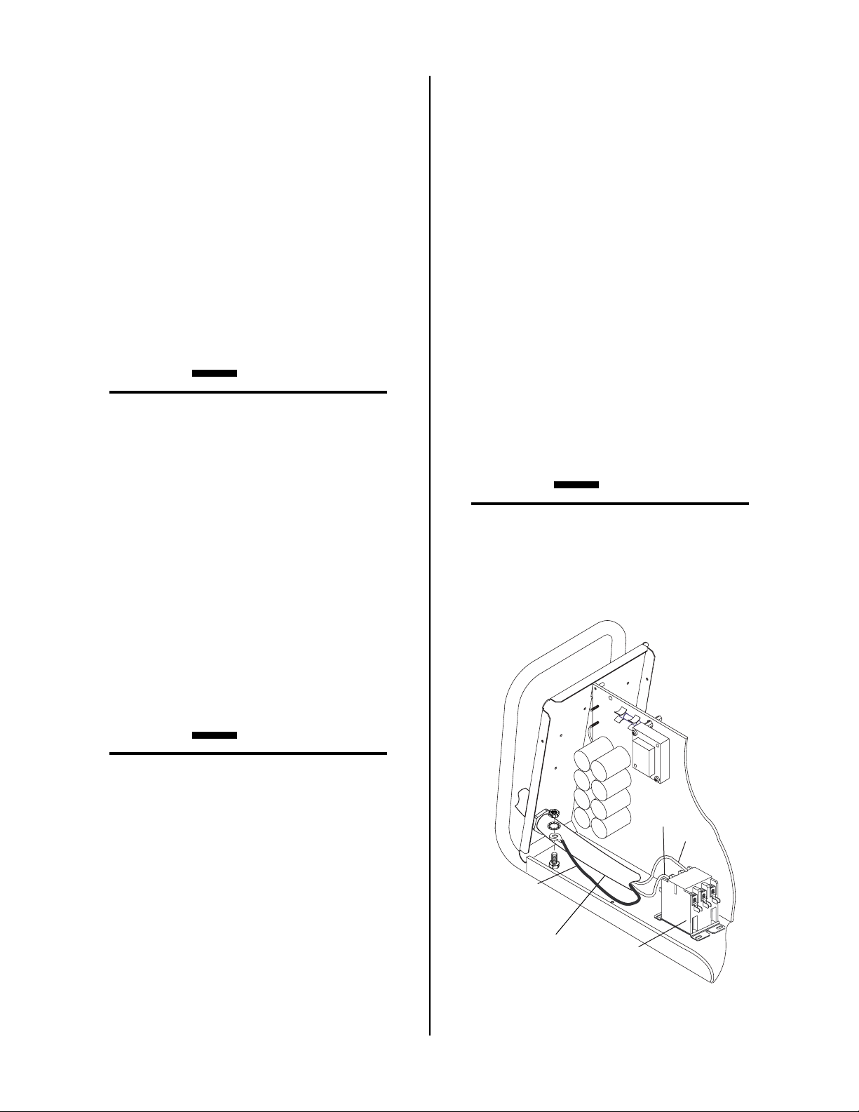
C. 460-Volt Single-Phase Operation
The 460-Volt Power Supply is equipped with a four-conductor input power cable for 460VAC, Three-Phase input power. The Power Supply will accept 460VAC,
Single-Phase input power with a change of input power
cable.
A. 208 / 230 Volt Units
This power supply includes a factory-installed input
power cable and plug.
1. Check your power source for correct voltage before plugging in the unit.
2. Connect the input power cable (or close the main
disconnect switch) to supply power to the system.
CAUTION
The primary power source and power cable must
conform to local electrical code and the recommended circuit protection and wiring requir ements
(refer to table in Appendix 1).
B. 400-Volt and 460-Volt Three-Phase Units
These Power Supplies are equipped with a three-phase,
four conductor, input power cable. Connect the input
power cable to the customer's power source as follows:
1. Remove the Power Supply cover per section 5.05.
2. The cable's outer covering is stripped back at the
factory to expose the individual wires at the free
end of the cable.
For 460-VAC, Single-Phase operation:
1. Remove the Power Supply cover per section 5.05.
2. Disconnect the original input power cable from
the main input contactor and the chassis ground
connection.
3. Loosen the strain relief on the back panel of the
power supply. Pull the original power cable out
of the power supply.
4. Pass a customer-supplied three-conductor input
power cable through the access opening in the
back panel of the power supply. Refer to Appendix 1 for power cable specifications. Tighten the
strain relief to secure the power cable.
CAUTION
The primary power source and power cable must
conform to local electrical code and the recommended circuit protection and wiring requir ements
(refer to table in Appendix 1).
3. Connect the ends of the individual wires to a customer supplied plug or main disconnect as follows:
CAUTION
The primary power source and power cable must
conform to local electrical code and the recommended circuit protection and wiring requir ements
(refer to table in Appendix 1). All the input cable
wires must be connected for three-phase operation.
• L1 wire to Line 1
• L2 wire to Line 2
• L3 wire to Line 3, refer to Caution above.
• Ground wire to Ground (Earth).
4. Replace the Power Supply cover.
5. Connect the input power cable (or close the main
disconnect switch) to supply power to the system.
L1
L3
L1 L2 L3
Ground Wire
with Ring
Terminal
Input Cable
A-03041
Main Input
Contactor
Input Power Connections, 460VAC, Single-Phase
INST ALLATION 3-2 Manual 0-2805
Page 15

5. Strip back the insulation on the individual wires
and connect as follows:
• Line 1 wire to main input contactor terminal
L1.
• Line 3 wire to main input contactor terminal
L3.
• Ground wire to Ground (Earth). The Ground
wire connection requires a ring terminal.
6. Replace the Power Supply cover.
7. Connect the input power cable (or close the main
disconnect switch) to supply power to the system.
3.06 Gas Connections
A. Gas Requirements
C. Connecting Gas Supply to Unit
The gas supply connects to the Regulator / Filter Assembly located on the rear of the unit. The connection is the
same for compressed air or high pressure gas cylinders.
If an optional air line filter is to be installed, refer to procedures in subsection 3.06-D.
1. Connect the gas line to the inlet port. The illustration
shows typical fittings as an example. Other fittings
may be used. Install the fittings and tighten.
NOTE
For a secure seal, apply thread sealant to the fitting threads, according to manufacturer's instructions. Do Not use Teflon tape as a thread sealer as
small particles of the tape may break off and block
the small gas passages in the torch.
WARNINGS
This unit is not to be used with oxygen (O2).
Maximum pressure at inlet must not exceed 125
psi (8.6 bar)
Gases: Single Gas - Plasma / Secondary
Compressed Air or Nitr ogen (N2) Only
Pressure: 70 psi (4.8 bar)
Flow: Cutting - 200 scfh (standard cubic feet / hr) (94.4
lpm)
Gouging - 230 scfh (standard cubic feet / hr) (108.5
lpm)
B. Checking Air Quality
To test the quality of air, place the RUN / SET switch to
SET position, place a welding filter lens in front of the
torch and turn on the gas. Any oil or moistur e in the air
will be visible on the lens. Do not initiate an arc!
Regulator/Filter
Assembly
Inlet Port
Bowl
1/4 NPT to 1/4"
(6mm) Fitting
Hose Clamp
Gas Supply
A-02999
Hose
Gas Connection to Regulator / Filter Assembly
CAUTION
Air supply must be free of oil, moisture, and other
contaminants. Excessive oil and moisture may
cause double-arcing, rapid tip wear, or even complete torch failure. Contaminants may cause poor
cutting performance and rapid electrode wear.
Manual 0-2805 3-3 INST ALLATION
Page 16

D. Installing Optional Air Filter Kits
2. Optional Two-Stage Air Filter Kit
Additional filtering is recommended when using air from
a compressor to ensure that moisture and debris fr om the
supply hose does not enter the torch. Although the Regulator has a filter , optional filter kits are recommended for
improved filtering.
1. Optional Single-Stage Air Filter Kit
This optional in-line air filter kit for use on compressed air shop systems is highly effective at removing moisture and particulate matter from the air
stream to at least 0.85 microns.
NOTE
For a secure seal, apply thread sealant to the fitting threads, according to the maker's instructions.
Do Not use Teflon tape as a thread sealer, as small
particles of the tape may break off and block the
small gas passages in the torch. Connect the gas
supply as follows:
a. Attach the Single-Stage Filter Hose to the
Regulator / Filter Assembly inlet port as
shown.
b. Attach the Single-Stage Filter Assembly to the
filter hose.
c. The illustration shows typical fittings as an
example. Other fittings may be used. Install
the fittings and tighten.
This optional two-stage air line filter is also for use
on compressed air shop systems. Filter removes moisture and contaminants to at least 5 microns.
Connect the gas supply as follows:
a. Attach the Two Stage Filter to the back of the
power supply per instructions supplied with
the filter assembly.
NOTE
For a secure seal, apply thread sealant to the fitting threads according to manufacturer's instructions. Do Not use Teflon tape as a thread sealer as
small particles of the tape may break off and block
the small gas passages in the torch.
b. Install the two stage filter hose in the inlet port
of the Regulator / Filter Assembly, as shown
below.
c. The illustration shows typical fittings as an
example. Other fittings may be used. Install
the fittings and tighten.
Regulator/Filter
Assembly
Regulator Inlet Port
2-Stage Filter
Inlet Port (IN)
Regulator/Filter
Assembly
Bowl
1/4 NPT Hose Fitting
Hose Clamp
1/4" (6 mm) Gas Supply Hose
Inlet Port
Optional Single-Stage Filter Installation
A-03000
Hose
Clamp
1/4" (6 mm) Gas
Supply Hose)
1/4 NPT
Hose Fitting
Optional Two-Stage Filter Installation
Outlet Port
(OUT)
Two Stage
Filter
Assembly
A-03004
INST ALLATION 3-4 Manual 0-2805
Page 17

E. Using High Pressure Gas Cylinders
Refer to the following when using high pressure gas cylinders as the gas supply:
A. Hand Systems
WARNING
CAUTION
Pressure should be set at 100 psi (6.9 bar) at the
high pressure gas cylinder regulator.
1. Refer to the manufacturer’s specifications for in-
stallation and maintenance procedures for high
pressure gas regulators.
2. Examine the cylinder valves to be sure they are
clean and free of oil, grease or any foreign mate-
rial. Momentarily open each cylinder valve to
blow out any dust which may be present.
3. The cylinder must be equipped with an adjust-
able high-pressure regulator capable of outlet
pressures up to 100 psi (6.9 bar) maximum and
flows of up to 200 scfh (94.3 lpm).
4. Use customer-supplied fitting(s) to connect 1/4"
(6 mm) inside diameter gas supply hose to the
cylinder.
NOTE
Supply hose must be at least 1/4 inch (6 mm) I.D.
For a secure seal, apply thread sealant to the fitting threads, according to manufacturer's instructions. Do Not use Teflon tape as a thread sealer as
small particles of the tape may break off and block
the small gas passages in the torch.
3.07 Torch Connections
Equipment ordered as a system will have the Torch factory connected to the Power Supply.
Disconnect primary power at the source before disassembling the torch or torch leads.
1. Remove the Cover of the Power Supply for access to the T orch Bulkhead Panel. See Section 5.05.
2. Remove the retaining nut from the Strain Relief.
Strain Relief
Torch Leads
Assembly
Negative /
Plasma Lead
A-03607
Pilot Lead
Strain Relief
Nut
Retaining Nut Removal
3. Feed the torch lead ends and the Strain Relief into
the hole in the unit.
4. Secure the Strain Relief with the retaining nut r emoved earlier .
5. Connect the torch Negative / Plasma Lead to the
bulkhead connection inside the Power Supply.
The instructions for connecting the Torch Leads to the
Power Supply are different depending on the type of
leads. This sub-section covers connecting the Torch for
the following applications:
A. Hand Systems
B. Machine Systems (Unshielded Leads)
C. Remote Pendant Contr ol (Optional)
The T orch Leads must be pr operly installed to the Power
Supply for proper operation. If the torch leads were not
factory-installed, make all torch connections to the T or ch
Bulkhead Panel for the desired application.
Manual 0-2805 3-5 INST ALLATION
Page 18

B. Machine Systems (Unshielded Leads)
Note: Actual Bulkhead
configuration may
differ from that shown.
Adapter
Adapter
Control Circuit
Connectors
Negative/Plasma
Lead Connection
Torch Lead
Assembly
Pilot Lead
Negative/Plasma
Lead
Connector
Pilot Lead Stud
A-03608
Torch Lead Connections To Bulkhead
6. Connect the Control (PIP) Circuit Connectors to
the mating connectors on the Power Supply
Adapter.
7. Remove the top nut and washer from the Pilot
Stud.
8. Place the lug on the Pilot Control Wire onto the
stud and secure with the nut and washer removed
in Step 7.
9. Tighten the Strain Relief onto the Torch Leads.
10. Check the torch for proper parts assembly.
CAUTION
1. Remove the Cover of the Power Supply to gain
access to the Torch Bulkhead Panel. See Section
5.05.
2. Remove the strain relief nut from the Strain Relief.
Torch Leads
Assembly
Remove Tie Wrap ,
Remove Insulator,
Disconnect Wires
A-03609
Strain Relief
Strain Relief
Nut
Strain Relief Nut Removal
3. The Adapter supplied with the Power Supply
must be installed as follows:
a. Inside the Power Supply Bulkhead area, route
the connector on the free end of the Adapter
through the Strain Relief Nut.
b. Continue routing the connector out the hole
in the front of the Power Supply.
c. Feed the end of the torch lead and the Strain
Relief into the hole in the unit while routing
the single black wire into the notch of the Strain
Relief.
The torch parts must correspond with the type of
operation. Refer to the appropriate torch manual
for proper parts selection.
11. Re-install the Power Supply Cover on the Power
d. Tighten the Strain Relief Nut to secure the
Strain Relief to the Power Supply.
4. Connect the torch Negative / Plasma Lead to the
bulkhead connection inside the Power Supply.
Supply.
INST ALLATION 3-6 Manual 0-2805
Page 19

Negative/Plasma
Lead Connection
Adapter
Connector
5. Connect the Control (PIP) Circuit Connectors to
the mating connectors on the Adapter supplied
on the Power Supply (see Warning).
Power Supply Adapter
Control Circuit
Remote
Pendant
Adapter
Torch Lead
Assembly
Connectors
Open
Pilot Lead
Negative/Plasma
Lead
Torch Lead Connections To Bulkhead
Power Supply Adapter
Control Circuit
Connectors
Open
Pilot Lead
Stud
A-03610
WARNING
The Adapter supplied with the Power Supply has
two additional Shield Connectors that are used for
Shielded Systems only. These two connectors are
not used and must be taped out of the way to prevent contacting the Negative / Plasma or Pilot
Leads.
6. Remove the top nut and washer from the Pilot
Stud.
7. Place the lug on the Pilot Control Wire onto the
stud and secure with the nut and washer removed
in the above Step.
8. Tighten the Strain Relief onto the Torch Leads.
9. Check the torch for proper parts assembly per the
torch manual.
CAUTION
The torch parts must correspond with the type of
operation. Refer to Section 4.04-A, Torch Parts
Selection.
Open
Torch Lead
Assembly
Negative/Plasma
Lead
Open
Pilot Lead
A-03611
Torch Lead Connections To Bulkhead - Detail
10. Reinstall the Power Supply Cover on the Power
Supply.
C. Remote Pendant Control (Optional)
In machine type operations the Power Supply has an
Adapter that has a cable connector supplied at each
end of the Adapter. One end is connected at the factory to the mating connector on the Power Supply
Bulkhead area. The other end allows connection of a
Remote Pendant. The remote pendant lead connector allows connection to a remote pendant or CNC
cable while using Control (PIP) Circuit connections
in the Torch Assembly.
Connect the remote pendant control cable to the connector provided on the Adapter fr om the Power Supply.
NOTE
Refer to Appendix 3, Torch Control Cable Wiring
Diagram For Mechanized Systems, for detailed
schematic of the Adapter.
Manual 0-2805 3-7 INST ALLATION
Page 20

Remote Pendant/CNC
Cable Connector
Control
12
OK-To-Move
14
13
2. Grounding for components mounted on the cutting
Torch Control
Cable Connector
2
3
4
PIP
Circuit
3
4
12
14
13
table (CNC controllers, height controllers, plasma remote controls, etc.) should follow the manufacturer’s
recommendations for wire size, type, and connection
point locations.
For Thermal Dynamics components it is recommended to use a minimum of 10 AWG (European 6
mm2) wire or flat copper braid with cross section equal
to or greater than 10 AWG connected to the cutting
table frame. The connection point must be clean bare
metal; rust and paint make poor connections. For all
components, wires larger than the recommended
minimum can be used and may improve noise protection.
3. The cutting machine frame is then connected to the
A-01366
“Star” point using 1/0 AWG (European 50 mm2) or
larger wire.
Remote Pendant Connector Diagram
3.08 Ground Connections For
Mechanized Applications
A. Electromagnetic Interference (EMI)
Pilot arc initiation generates a certain amount of electromagnetic interference (EMI), commonly called RF noise.
This RF noise may interfere with other electronic equipment such as CNC controllers, remote controls, height
controllers, etc. T o minimize RF interference, follow these
grounding procedures when installing mechanized systems:
B. Grounding
1. The preferred gr ounding arrangement is a single point
or “Star” ground. The single point, usually on the
cutting table, is connected with 1/0 AWG (European
50 mm2) or larger wire to a good earth ground (refer
to paragraph ‘C’, Creating An Earth Ground). The
ground rod must be placed as close as possible to the
cutting table, ideally less than 10 ft (3.0 m), but no
more than 20 ft (6.1 m).
NOTE
All ground wires should be as short as possible.
Long wires will have increased resistance to RF
frequencies. Smaller diameter wire has increased
resistance to RF frequencies, so using a larger diameter wire is better .
4. The plasma power supply work cable (see NOTE) is
connected to the cutting table at the single point “Star”
ground.
NOTE
Do Not connect the work cable directly to the
ground rod.
5. Make sure work cable and ground cables are properly connected. The work cable must have a solid
connection to the cutting table. The work and ground
connections must be free from rust, dirt, grease, oil
and paint. If necessary grind or sand down to bare
metal. Use lock washers to keep the connections tight.
Using electrical joint compound to prevent corrosion
is also recommended.
6. The plasma power supply chassis is connected to the
power distribution system ground as required by electrical codes. If the plasma supply is close to the cutting table (see NOTE) a second ground rod is not usually needed, in fact it could be detrimental as it can
set up ground loop currents that cause interference.
When the plasma power supply is far away from the
ground rod and interference is experienced, it may
help to install a second earth ground rod next to the
plasma power supply. The plasma power supply
chassis would then be connected to this ground rod.
NOTE
It is recommended that the Plasma Power Supply
be within 20 - 30 ft (6.1 – 9.1 m) of the cutting
table, if possible.
INST ALLATION 3-8 Manual 0-2805
Page 21

7. The plasma control cable should be shielded with the
shield connected only at the cutting machine end.
Connecting the shield at both ends will allow ground
loop currents which may cause more interference than
with no shield at all.
C. Creating An Earth Ground
1. T o cr eate a solid, low resistance, earth ground, drive a
1/2 in (12 mm) or greater diameter copper clad ground
rod at least 6 - 8 ft (1.8 - 2.4 m) into the earth so that
the rod contacts moist soil over most of its length.
Depending on location, a greater depth may be required to obtain a low resistance ground (see NOTE).
Ground rods, typically 10 ft (3.0 m) long, may be
welded end to end for greater lengths. Locate the rod
as close as possible to the work table. Install a ground
wire, 1/0 A WG (European 50 mm2) or greater , between
the ground rod and the star ground point on the cutting table.
NOTE
Ideally, a properly installed ground r od will have a
resistance of three ohms or less.
T o test for a pr oper earth ground, refer to the following diagram. Ideally, the reading on the multimeter
should be as follows:
2. Increasing the ground rod length beyond 20 - 30 ft
(6.1 – 9.1 m) does not generally increase the effectiveness of the ground rod. A larger diameter rod which
has more surface area may help. Sometimes keeping
the soil around the ground rod moist by continuously
running a small amount of water into it will work.
Adding salt to the soil by soaking it in salt water may
also reduce its resistance. When these methods are
used, periodic checking of the ground resistance is required to make sure the ground is still good.
D. Routing Of Torch Leads
1. To minimize RF interference, position torch leads as
far as possible from any CNC components, drive motors, control cables, or primary power lines. If cables
have to pass over torch leads, do so at an angle. Do
not run the plasma control or other control cables in
parallel with the torch leads in power tracts.
2. Keep torch leads clean. Dirt and metal particles bleed
off energy, which causes difficult starting and increased chance of RF interference.
• For 115VAC: 3.0 VAC
• For 230VAC: 1.5 VAC
115VAC: 3.0 VAC
230VAC: 1.5 VAC
V
Meter set to
VAC setting
WARNING
Use extreme caution. This
test uses live voltage.
Neutral
115 or 230VAC
Line (Hot)
A-02971
100W
Light Bulb
~
~
V
VR COM A
_
+
Machine
Earth Ground
Ground Testing
Manual 0-2805 3-9 INST ALLATION
Page 22

INST ALLATION 3-10 Manual 0-2805
Page 23

SECTION 4:
OPERATION
4.01 Introduction
This section identifies the front and rear components and
describes the power supply operating controls and procedures.
4. Roll Handle / Torch Leads Wrap
The torch leads and work cable wrap around the
handle for easy storage.
5. Torch Bulkhead Panel
The torch bulkhead panel is under the power supply cover. See Section 5.05 for cover removal directions.
A. Pilot Lead Stud
4.02 Product Features
This subsection provides specific functional descriptions
of the power supply operating controls and indicators.
A. Front Panel Features
1. Control Panel
All operator controls, except gas pressure adjustment,
are located on this panel: power ON / OFF switch,
RUN / SET switch; CURRENT control; LED indicators for AC Power, TEMP, GAS, and DC.
2
4
1
Connects the pilot control wire on the torch to the
unit.
B. Control Cable Connector
Connects the torch switch to the unit. In machine
torch applications connects the torch switch on the
pendant to the unit.
C. Gas / Power Lead Connection
Connects the torch gas / negative lead to the unit.
A-02772
Front Panel Features
2. Torch Leads Input
Hole in the front panel to feed the torch leads through
to the internal bulkhead connections.
3. Work Cable and Clamp
20 ft (6.1 m) work cable with clamp, factory installed.
Manual 0-2805 4-1 OPERATION
3
Page 24

B. Control Panel Features
6. GAS Indicator
A
30
25
3
20
1
Operating Controls
1. ON / OFF Power Switch
ON position supplies AC power to activate all system control circuits. OFF position deactivates control circuits.
35
40
A-03641
Green indicator will come ON when the input gas
4
5
6
7
pressure is set to 35 psi (2.4 bar) or higher. Indicator
will be OFF when the pressure falls below 35 psi (2.4
bar).
7. DC Indicator
Green indicator will come ON while the torch is activated. Indicates DC output circuit is active.
C. Rear Panel Features
2
1. Gas Input Port
Connection for gas input.
WARNING
This unit is not to be used with oxygen (O2).
1
2. RUN / SET
Switch
RUN position is used for general torch operation.
Torch switch must be held. SET position used for
setting gas pressure and purging lines.
3. Current Control (A)
Adjustment to set the desired output current between
20-40 amps.
4. AC Power Indicator
Green indicator will blink ON-OFF for approximately
eight seconds and then stay ON after the ON /
OFF power switch is set to ON. Indicates operating
power is present in the unit.
5.
TEMP Indicator
Normally OFF . Y ellow indicator will come ON when
the internal temperature sensors detect temperatures
above normal limits. The unit should be allowed to
cool before continuing operation.
3
2
A-03042
Rear Panel
2. Primary Input Power Cable / Strain Relief
Primary input power cable with strain relief, capable
of handling the input voltage for which this unit was
designed.
3. Gas Pressure Filter / Regulator Assembly
Pressure regulator to adjust the input gas pr essure to
the Power Supply . The pr essure regulator has its own
built-in filter . Factory installed. For improved filter-
ing, other filtering packages are available as options.
OPERA TION 4-2 Manual 0-2805
Page 25

4.03 Preparations For Operating
I. Prepare to Cut
This procedure should be followed at the beginning of
each shift:
WARNING
Disconnect primary power at the source before assembling or disassembling power supply, torch
parts, or torch and leads assemblies.
A. Torch Parts Selection
Check the torch for proper assembly and appropriate front end torch parts. The tor ch parts (shield cup,
tip, gas distributor, and electrode) must correspond
with the type of operation (cutting or gouging). Refer to the torch manual for proper parts selection.
B. Check Primary Input Power Source
1. Check the power source for pr oper input voltage.
Make sure the input power source meets the
power requirements for the unit per subsection
2.03-A, Specifications / Design Features.
2. Connect the input power cable (or close the main
disconnect switch) to supply power to the system.
C. Gas Selection
Select desired single gas supply . Make sur e gas source
meets requirements (refer to subsection 3.06A, Gas
Requirements). Check connections and turn gas supply on.
Return the RUN / SET switch to RUN position. Gas
will not flow until the Torch Trigger is pressed.
The system is now ready for operation. Activate the
torch (press torch switch on the handle, send START
signal from CNC or press the torch switch on the Remote Pendant). There is a 2 second pre-flow before
the arc starts.
4.05 Sequence of Operation
The following is a typical sequence of operation for this
power supply. Refer to Appendix 2 for block diagram.
1. Close main power source disconnect switch.
a. AC power is available at the Power Supply.
2. Place RUN / SET switch to RUN mode.
3. Place the ON / OFF power switch on the front
panel of the Power Supply to ON position.
a. AC Power Indicator blinks ON and OFF
for eight seconds then stays ON. Fan turns on.
NOTE
Gas comes on if T or ch Trigger is pressed (although
unit will not pilot until switch is released and reclosed after the light stops blinking).
4. Place RUN / SET switch to SET mode.
a. Gas solenoid opens and gas flows to set pres-
sure. Gas Pressure Regulator / Filter Assembly should be set to 70 psi (4.8 bar). GAS indi-
D. Work Cable Connection
Check for a solid work cable connection to the workpiece.
E. Torch Connection
Check that the torch is properly connected.
F. Power On
On the Power Supply place the ON / OFF switch to
the ON position.
G. Select Current Output Level
On the Control Panel, set the desired current output
level between 20-40 amps for cutting or gouging.
H. Set Operating Pressure
Place the RUN / SET switch to the SET position. Gas
will flow. Adjust gas pressure control to 70 psi (4.8
bar).
Manual 0-2805 4-3 OPERATION
cator turns ON.
NOTE
GAS Indicator will not come ON if the gas pressure is set below 35 psi (2.4 bar) at the Gas Pressure Regulator / Filter Assembly.
5. Place RUN / SET switch to RUN mode.
a. Gas flow stops. GAS Indicator turns OFF.
6. Protect eyes and activate torch.
a. Gas pre-flow starts (approximately 2 seconds).
GAS Indicator turns ON.
7. After gas pre-flow:
a. Power Supply enabled. DC indicator
turns ON. Pilot Relay closes.
8. Pilot arc is established
Page 26

9. Move T orch within transfer distance of workpiece.
a. Main arc transfers. Pilot arc OFF.
10. Complete cutting operation.
NOTE
If the torch is lifted from the workpiece while the
torch switch is activated, the main arc will stop
and the pilot arc will automatically restart.
11. Release or deactivate the torch switch.
a. Main arc stops. Pilot arc stops.
If torch is activated during post-flow, the pilot arc will immediately restart. If torch is
within 1/4 inch (6.4 mm) transfer distance to
workpiece, the main arc will transfer.
12. Gas will flow for 10 seconds (post-flow).
a. Gas solenoid closes. Gas flow stops. GAS in-
dicator turns OFF.
13 Place the ON / OFF power switch on the front
panel of the unit to OFF.
a. AC Power indicator turns OFF . Fan turns OFF .
14. Place the main power disconnect to open.
a. Main AC power is r emoved fr om the system.
For information on cutting techniques, cutting problems,
cutting speeds, cut quality , etc., r efer to the torch manual
supplied with the torch.
OPERA TION 4-4 Manual 0-2805
Page 27

SECTION 5:
SERVICE
5.01 Introduction
This section describes basic maintenance procedures performable by operating personnel. No other adjustments
or repairs are to be attempted other than by properly trained
personnel.
5.02 General Maintenance
A. Maintenance Schedule
W ARNING
Disconnect primary power to the system before disassembling the torch, leads, or power supply.
5. The filter element and spool, with the baffle ring
in place (teeth facing downward) can be screwed
back into the Regulator body by compressing the
spring on the spool. Tighten firmly by hand.
Regulator/Filter
Assembly
Baffle
Ring
Filter
Element
Spring
Spool
To clean the unit, open the enclosure per procedures in
Section 5.05-A, Cover Removal, and use a vacuum cleaner
to remove any accumulated dirt and dust. The unit should
also be wiped clean. If necessary, solvents for cleaning
electrical apparatus may be used.
Refer to Appendix 4 for maintenance schedule and procedures.
B. Regulator / Filter Element Replacement
The Regulator / Filter Assembly is on the rear panel. For
better system performance, the Regulator / Filter Assembly filter element should be checked per the Maintenance
Schedule, and either cleaned or replaced. Refer to Section
6, Parts List, for replacement filter element catalog number. The Regulator / Filter Assembly may vary; the replacement element and the replacement procedure are the
same for both types of Regulator / Filter .
1. Remove power from the power supply; turn off the
gas supply.
2. Unscrew the bowl on the bottom of the Regulator /
Filter Assembly. The filter element will be visible
and still attached to the main body of the Regulator / Filter
3. Grasp the filter element and unscrew it from the
Regulator / Filter body. The filter element will
come off with a spool and some additional pieces.
4. Note the correct assembly of the filter / spool then
remove the filter from the spool and either clean it
or replace it.
Bowl
A-02995
Regulator / Filter Element Replacement
6. Reinstall the bowl.
7. Turn on the air supply .
C. Optional Single-Stage Filter Element
Replacement
These instructions apply to power supplies where the optional Single-Stage Filter has been installed.
The Power Supply shuts down automatically when the
Filter Element becomes completely saturated. The Filter
Element can be removed from its housing, dried, and reused. Allow 24 hours for Element to dry. Refer to Section
6, Parts List, for replacement filter element catalog number .
1. Remove power from power supply.
2. Shut off air supply and bleed down system before
disassembling Filter to change Filter Element.
3. Disconnect gas supply hose from barbed fitting.
4. Turn the Cover counter-clockwise and remove it
from the Filter Housing. The Filter Element is located inside the Housing.
5. Remove the Filter Element from the Housing and
set Element aside to dry .
Manual 0-2805 5- 1 SERVICE
Page 28

Housing
Filter
Element
(Cat. No. 9-7741)
Spring
3. Loosen the two bolts on the top of the Filter Assembly enough to allow the Filter Elements to move
freely.
O-ring
Cover
Barbed
Fitting
Assembled Filter
A-02476
Optional Single-Stage Filter Element Replacement
6. Wipe inside of housing clean, then insert the replacement Filter Element open side first.
7. Replace Housing on Cover .
8. Reattach gas supply hose to barbed fitting.
NOTE
If unit leaks between housing and cover , inspect the
"O" Ring for cuts or other damage.
D. Optional Two-Stage Filter Element
Replacement
These instructions apply to any power supply where the
optional T wo-Stage Filter has been installed.
The Two-Stage Air Filter has two Filter Elements. When
the Filter Elements become dirty the Power Supply will
continue to operate but cut quality may become unacceptable. Refer to Section 6, Parts List, for replacement filter
element catalog number .
1. Remove power from power supply.
2. Shut off air supply and bleed down system before
changing Filter Elements.
First & Second
Stage
Cartridges
(as marked)
A-02942
Two-Stage Filter Replacement
4. Note the location and orientation of the old Filter
Elements.
5. Slide out the old Filter Elements.
6. Slide the replacement Filter Elements into the Filter Assembly, with the same orientation as noted
in Step 4 above.
7. Hand tighten the two bolts evenly , then torque each
bolt to 20 - 30 in-lbs (2.3 - 3.4 Nm).
8. Slowly apply air pressure to the assembly, checking for leaks.
5.03 Common Faults
1. Insufficient Penetration
a. Cutting speed too fast
b. T or ch tilted too much
c. Metal too thick
d. Worn torch parts
W ARNING
e. Cutting current too low
f. Non-Genuine Thermal Dynamics parts used
Always turn off the air supply and bleed the system
before disassembling the Filter Assembly as injury
could result.
SERVICE 5-2 Manual 0-2805
Page 29

2. Main Arc Extinguishes
a. Cutting speed too slow
b. Torch standoff too high from workpiece
c. Cutting current too high
d. Work cable disconnected
e. Worn torch parts
f. Non-Genuine Thermal Dynamics parts used
3. Excessive Dross Formation
a. Cutting speed too slow
b. Torch standoff too high from workpiece
c. Worn torch parts
d. Improper cutting current
e. Non-Genuine Thermal Dynamics parts used
For major troubleshooting and parts replacement procedures refer to Power Supply Service Manual 0-2806.
B. How to Use This Guide
The following information is a guide to help the Customer
/ Operator determine the most likely causes for various
symptoms. Follow all instructions as listed and complete
each section in the order presented.
This guide is set up in the following manner:
X. Symptom (Bold T ype)
Any Special Instructions (T ext T ype)
1. Cause (Italic T ype)
a. Check / Remedy (T ext T ype)
Locate your symptom, check the causes (easiest listed
first), then remedies. Repair as needed being sure to
verify that unit is fully operational after any repairs.
4. Short T orch Parts Life
a. Oil or moisture in air source
b. Exceeding system capability (material too thick)
c. Excessive pilot arc time
d. Air flow too low (incorrect pressure)
e. Improperly assembled torch
f. Non-Genuine Thermal Dynamics parts used
5.04 Basic Troubleshooting Guide
W ARNING
There are extremely dangerous voltage and power
levels present inside this unit. Do not attempt to
diagnose or repair unless you have had training in
power electronics measurement and troubleshooting techniques.
A. Basic Troubleshooting: Overview
This guide covers a basic level of troubleshooting that re-
quires limited disassembly and measurements. It is helpful for solving many of the common problems that can
arise with this system.
If major complex subassemblies are faulty, the unit must
be returned to an authorized service center for repair .
Follow all instructions as listed and complete each section in the order presented.
C. Common Symptoms
A. AC Power indicator OFF
1. Switch at customer's main power panel in OFF position.
a. Close main power panel switch.
2. Customer's main power line fuse(s) blown
a. Check main power panel fuse(s) and replace as
required.
3. Actual input voltage does not correspond to voltage of
unit
a. Verify that the input line voltage is correct. Re-
fer to Appendix 1, Input W iring Requirements.
4. Unit internal fuse blown or loose
a. If blown, double check input voltage and re-
place fuse per subsection 5.05-B. If fuse blows
again, return unit to an authorized service center .
5. Faulty components in unit
a. Return for repair or have qualified technician
repair per Service Manual.
B. AC Power indicator ON; TEMP indicator ON
1. Airflow obstructed
a. Check for obstructed air flow around the unit
and correct condition.
2. Fan blocked
a. Check and correct condition.
Manual 0-2805 5- 3 SERVICE
Page 30

3. Unit is overheated
F . Limited output with no control
a. Allow unit to cool down for at least 5 minutes.
Make sure the unit has not been operated beyond Duty Cycle limit. Refer to Section 2.03.
4. Input line voltage is below 75% of rated level
a. Check and connect to proper input power line.
5. Faulty components in unit
a. Return for repair or have qualified technician
repair per Service Manual.
C. T orch will not pilot when torch switch is activated
1. RUN / SET switch in SET position
a. Move switch to RUN position.
2. Faulty torch parts
a. Inspect torch parts and replace if necessary (re-
fer to Instruction Manual supplied with torch).
3. Gas pressure too high or too low
a. Set pressure to 70 psi (4.8 bar).
4. Faulty components in unit
a. Return for repair or have qualified technician
repair per Service Manual.
1. Poor input or output connections
a. Check all input and output connections.
2. Faulty components in unit
a. Return for repair or have qualified technician
repair per Service Manual.
G. Erratic or improper cutting output
1. Poor input or output connections
a. Check all input and output connections.
2. Poor ground or work connection is poor .
a. Check connection.
H. Arc shuts off during operation; Arc will not re-start
when torch switch is activated.
1. Unit is overheated (TEMP indicator ON)
a. Allow unit to cool down for at least 5 minutes.
Make sure the unit has not been operated beyond Duty Cycle limit. See Section 2 for duty
cycle specifications.
2. Fan blades blocked (TEMP indicator ON)
a. Check and clear blades.
D. No cutting output; T orch activated; AC Power
indicator ON; Gas flows; Fan operates
1. Torch not properly connected to power supply
a. Check that torch leads are properly attached to
power supply .
2. Shield cup not properly installed on torch
a. Check that shield cup is fully seated against
torch head. Refer to the torch manual for details.
3. Faulty components in unit
a. Return for repair or have qualified technician
repair per Service Manual.
4. Faulty Torch
a. Return for repair or have qualified technician
repair per T or ch Manual.
E. Low cutting output
1. Incorrect setting of CURRENT control
a. Check and adjust to proper setting.
2. Faulty components in unit
3. Airflow obstructed (TEMP indicator ON)
a. Check for obstructed air flow around the unit
and correct condition.
4. Gas pressure too low (GAS indicator OFF when torch
switch is activated)
a. Check source for at 70 psi (4.8 bar); adjust as
needed.
5. Faulty components in unit
a. Return for repair or have qualified technician
repair per Service Manual.
I. No gas flow; AC POWER indicator ON; Fan
operates
1. Gas not connected or pressure too low
a. Check source for at least 70 psi (4.8 bar).
2. Gas supply pressure too high
a. Maximum 125 psi (8.6 bar) inlet pressure
3. Shield Cup not properly installed.
a. Check to see that Control Circuit (PIP) pins are
installed. Refer to the torch manual for details.
a. Return for repair or have qualified technician
repair per Service Manual.
SERVICE 5-4 Manual 0-2805
Page 31

4. Faulty components in unit
a. Return for repair or have qualified technician
repair per Service Manual.
J. T orch cuts but not adequately
1. Current set too low
a. Increase current setting.
2. Torch is being moved too fast across workpiece
a. Reduce cutting speed (refer to T orch Instruction
Manual supplied with torch).
3. Excessive oil or moisture in torch
a. Hold torch 1/8 inch (3 mm) from clean surface
while purging and observe oil or moisture
buildup (do not activate torch).
5.05 Power Supply Basic Parts Replacement
W ARNING
2. Loosen, but do not remove, the lower screws,
then carefully pull the Cover up and away
from the unit for access to the inside of the
unit.
Upper screws
Lower screws
Ground wire
Disconnect primary power to the system before disassembling the torch, leads, or power supply.
This section describes procedures for basic parts replacement. For more detailed parts replacement procedures,
refer to the Power Supply Service Manual.
A. Cover Removal
1. Remove the upper screws which secure the cover
to the main assembly .
NOTE
There is a ground wire connection to the inside of
the unit. There is no need to disconnect the ground
wire, unless there is a need for more room to work.
A-02776
Cover Removal
3. To reinstall the cover, complete the following:
a. Reconnect the ground wire, if necessary.
b. Place the cover onto the frame so that it
rests on the lower screws.
c. Tighten lower screws.
d. Reinstall and tighten the upper screws.
Manual 0-2805 5- 5 SERVICE
Page 32

B. Fuse Replacement
1. Remove the unit cover per paragraph "A" above.
2. Locate the internal fuse on the left side of the center chassis.
3. Replace the fuse. Refer to Section 6.04 for proper
fuse specification.
4. Reinstall the cover by reversing the steps in paragraph "A" above.
Fuse Location
A-02957
Internal Fuse Location
This completes the parts replacement procedures.
SERVICE 5-6 Manual 0-2805
Page 33

SECTION 6:
PARTS LISTS
6.01 Introduction
A. Parts List Breakdown
The parts list provide a breakdown of all r eplaceable components. The parts lists are arranged as follows:
Section 6.03 Complete Power Supply Replacement
Section 6.04 Replacement Parts
Section 6.05 Options and Accessories
NOTE
Parts listed without item numbers are not shown,
but may be ordered by the catalog number shown.
B. Returns
If a product must be returned for service, contact your
distributor. Materials returned without proper authorization will not be accepted.
6.02 Ordering Information
Order replacement parts by catalog number and complete
description of the part or assembly, as listed in the parts
list for each type item. Also include the model and serial
number of the torch. Addr ess all inquiries to your authorized distributor .
Manual 0-2805 6-1 P ARTS LISTS
Page 34

6.03 Power Supply Replacement
A-02958
The following items are included with the replacement power supply: work cable & clamp, gas pressur e regulator /
filter , and operating manual.
Qty Description Catalog #
CutMaster 50 Power Supply
1 208 / 230VAC, Single Phase, 60Hz, with input power cable and plug 3-5230
1 400VAC, Three Phase, 50 / 60Hz, with input power cable (only) 3-5230-3
1 460VAC, Three Phase, 50 / 60Hz, with input power cable (only) 3-5230-2
6.04 Replacement Parts
Qty Description Catalog #
1 Filter / Regulator Assembly Replacement Element 9-4414
1 Fuse
1/2A, 250V (for 208 / 230 Volt units) 9-6395
1/2A, 600V (for 400 Volt and 460 Volt units) 9-8110
6.05 Options and Accessories
Qty Description Catalog #
1 Single Stage Filter Kit (includes Filter & Hose) 7-7507
1 Replacement Filter Body 9-7740
1 Replacement Filter Hose 9-7742
2 Replacement Filter Element 9-7741
1 Two Stage Filter Kit (includes Hose & Mounting Screws) 7-7500
1 Bracket, Filter Mounting (not shown) 9-7535
1 Two Stage Air Filter Assembly 9-7527
1 First Stage Cartridge 9-1021
1 Second Stage Cartridge 9-1022
1 Extended Work Cable (50 ft / 15.2 m) with Clamp 9-8529
1 Wheel Kit 9-8510
1 Multi Purpose Cart 7-8888
First & Second
Stage
Cartridges
(as marked)
A-02942
Optional Two Stage Filter Kit
PARTS LISTS 6-2 Manual 0-2805
Wheel Kit, installed
Page 35

APPENDIX 1: INPUT WIRING REQUIREMENTS
Input Power Input Current Input Sugges t ed Sizes (See Notes )
Voltage Freq. 1-Ph 3-Ph 1-Ph 3-Ph
(Volts) (Hz.) (kVA) (kVA) (Amps) (Amps) 1-Ph 3-Ph 1-Ph 3-Ph 1-Ph 3-Ph
208 60 9 42 60 10 10
230 60 9 37 60 10 10
400 50 8 11 15 12 12
400 60 8.5 12 15 12 12
460601417.5251212
460 60 8 10 15 12 12
460501417.5251212
460 50 8 9.5 15 12 12
Line Vol t ages with Sugges ted Circuit Protec t ion and Wire Si zes
Bas ed on Nat ional E l ec tric Code and Canadian El ec t ri c Code
Refer to Local and National Codes or local authority having jurisdiction for proper wiring requirements.
Cable size is de rated based on the Duty Cycle of the equipment.
The suggested sizes are based on flexible power cable with power plug installations. For hard wired installations refer
to local or national codes.
Fuse (A m ps) W ire (A WG) Wi re (Canada)
NOTES
Cable conductor temperature used is 167° F (75° C).
An energy limiting fuse UL Class RK 1 (examples: BUSS LPS / LPN RK or Gould Shawmut AZK A6K) should be
used to minimize damage to Plasma Cutting, Welding or power distribution equipment.
NEVER use replaceable element fuses like UL Class H, or "one time" fuses like UL Class K5.
Manual 0-2805 A-1 APPENDIX
Page 36

APPENDIX 2: SEQUENCE OF OPERATION
(BLOCK DIAGRAM)
ACTION
Close external
disconnect switch.
RESULT
Power to system.
ACTION
Protect eyes and
activate torch.
RESULT
Gas flows (2 seconds).
After gas pre-flow:
DC indicator on.
Pilot arc established
ACTION
ON/OFF switch
to ON.
RESULT
AC indicator blinks for 8
seconds then steady on.
Fans on.
Pilot relay closes.
Power circuit ready.
gas flows to set pressure.
PILOT ARC
ACTION
RUN/SET switch
to SET.
RESULT
Gas solenoid open,
GAS indicator on.
ACTION
RUN/SET
switch to RUN.
RESULT
Gas flow stops.
GAS indicator off.
ACTION
Torch moved away
from work (while
still activated).
RESULT
Main arc stops.
Pilot arc automatically
restarts.
ACTION
Torch deactivated (by torch switch
release or by remote device).
RESULT
(Power supply enable signal removed)
post-flow, pilot arc will immediately restart.
(1/4 in/6.4mm) of workpiece, main arc
Gas solenoid closes, gas flow stops.
Main arc stops.
Gas flows (10 seconds)
NOTE - If torch is activated during
If torch is within transfer distance
will transfer.
After post-flow:
GAS indicator off.
ACTION
ON/OFF switch
to OFF
RESULT
All indicators off.
Power supply fans off.
ACTION
Torch moved within
transfer distance of workpiece.
RESULT
Main arc transfer.
Pilot arc off.
ACTION
Open external
disconnect.
RESULT
No power to system
A-03568
APPENDIX A-2 Manual 0-2805
Page 37

APPENDIX 3: TORCH CONTROL CABLE WIRING
DIAGRAM
This diagram applies to mechanized systems only.
T o Torch
Control Device
Torch Control
Cable
Torch Control
Connectors
Control Connector
Plug with Connectors
To Power Supply
Control Connector
Control Shield
Connector
Shield
Return
Power Supply
Control
OK-To-Move
Relay
A-02821
12
14
Torch Lead
Assembly
Mate & Lock
2
1
3
4
Connectors
Lead Shield
Connector
Torch Leads
Connectors only on
Shielded Leads
Mate & Lock
Connectors
Torch Head
PIP Pin
Shield Cup
PIP Pin
3
4
12
OK-To-Move
14
A-02801
Control
13
Torch Control
Cable Connector
Remote Pendant/CNC
13
Pendant Ground
Cable Connector
Manual 0-2805 A-3 APPENDIX
Page 38

APPENDIX 4: MAINTENANCE SCHEDULE
This schedule applies to all types of non liquid cooled plasma cutting systems. Some systems will not have all the parts
listed and those checks need not be performed.
NOTE
The actual frequency of maintenance may need to be adjusted according to the operating environment.
Daily Operational Checks or Every Six Cutting Hours:
1. Check torch consumable parts, replace if damaged or worn.
2. Inspect torch for any cracks or exposed wires, r eplace if necessary.
3. Check plasma and secondary supply and pressure / flow.
4. Purge plasma gas line to remove any moisture build up.
5. Inspect input power cable for damage or exposed wires, r eplace if necessary .
Weekly or Every 30 Cutting Hours:
1. Check fan for proper operation and adequate air flow .
2. Blow or vacuum dust and dirt out of the entire machine.
CAUTION
Do not blow air into the power supply during cleaning. Blowing air into the unit can cause metal particles to interfere
with sensitive electrical components and cause damage to the unit.
Six Months or Every 720 Cutting Hours:
1. Check the in line air filter(s), clean or replace as required
2. Check cables and hoses for leaks or cracks, replace if necessary.
3. Check all contactor points for severe ar cing or pits, replace if necessary.
APPENDIX A-4 Manual 0-2805
Page 39

Notes:
Manual 0-2805 A-5 APPENDIX
Page 40

APPENDIX 5: SYSTEM SCHEMATIC FOR 208 / 230V UNITS
A-03269
APPENDIX A-6 Manual 0-2805
Page 41

A-03269
Manual 0-2805 A-7 APPENDIX
Page 42

APPENDIX 6: SYSTEM SCHEMATIC FOR 400 / 460V UNITS
A-02967
APPENDIX A-8 Manual 0-2805
Page 43

A-02967
Manual 0-2805 A-9 APPENDIX
Page 44

APPENDIX A-10 Manual 0-2805
 Loading...