

Page 1
Manual 0-4964
82 Benning Street, West Lebanon, NH 03784 USA
(603) 298-5711 • www.thermal-dynamics.com
Unpacking
The product is packaged and protected to prevent damage
during shipping. Inspect for possible shipping damage. If
damage is evident, contact your distributor and/or shipping
company before proceeding with installation.
General Information
This kit is for use only with Thermal Dynamics UltraCut®
Power Supplies and XT-300 Torches. Do not use this kit
with any other equipment.
This kit requires the C.C.M. (Communication Control Module) Firmware to have version 3.2 or higher and a change
in DIP switch settings. See your authorised service center
for this update.
This kit requires the GCM 2010 Firmware to be 3.1 or higher. See your authorised service center for this update.
Art # A-07644
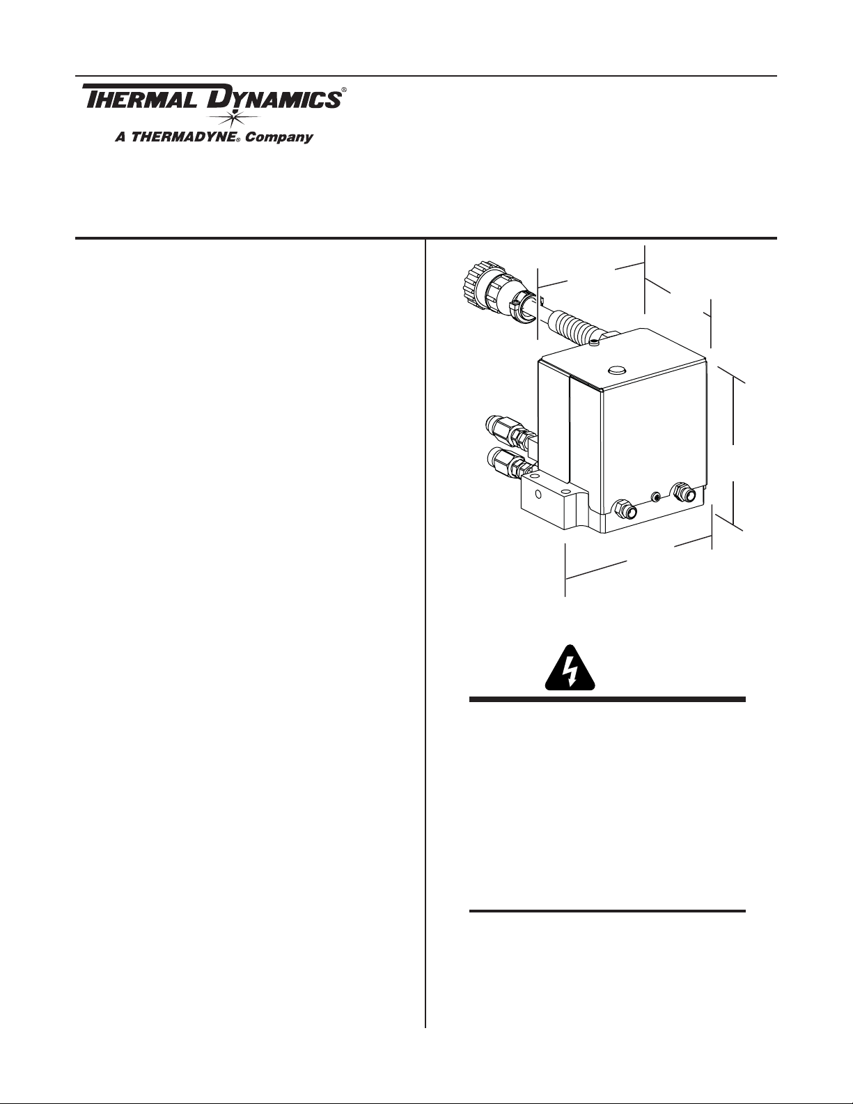
XTL Torch Valve Kit No. 4-3054
Installation Instructions
3.72 in
95 mm
2.9 in
73.66 mm
4.31 in
109 mm
5 in
127 mm
This kit accepts prefl ow, plasma, shield and Water Mist
Secondary™ gases from the Gas Control Module and
supplies these gases to the Torch.
Supplied Parts
• XTL Torch Valve Assembly
• 4’ Plasma Hose
• 4’ Shield Hose
• 4 Fuses
• Fuse Rating Label
• Installation Instructions
Installation
WARNINGS
Disconnect primary power at the source.
1. In most cases the XTL Valve Kit may be mounted in the
same location as the old one. If not, mount it as close
as possible to the Torch. The valve kit can be mounted
in any convenient position, provided the outlet side
(with two fi ttings) is closer to the torch than the inlet
side (with four fi ttings and a control cable connector).
Dimensions given in the following illustration are to assist in locating mounting holes and hardware length.
NOTE
Care must be taken when considering the
mounting location so the exhaust muffler
on top of the assembly is not covered or
blocked.
© 2007 Thermadyne Corp.
February 5, 2007
1
Manual 0-4964 Rev AA.01
Page 2
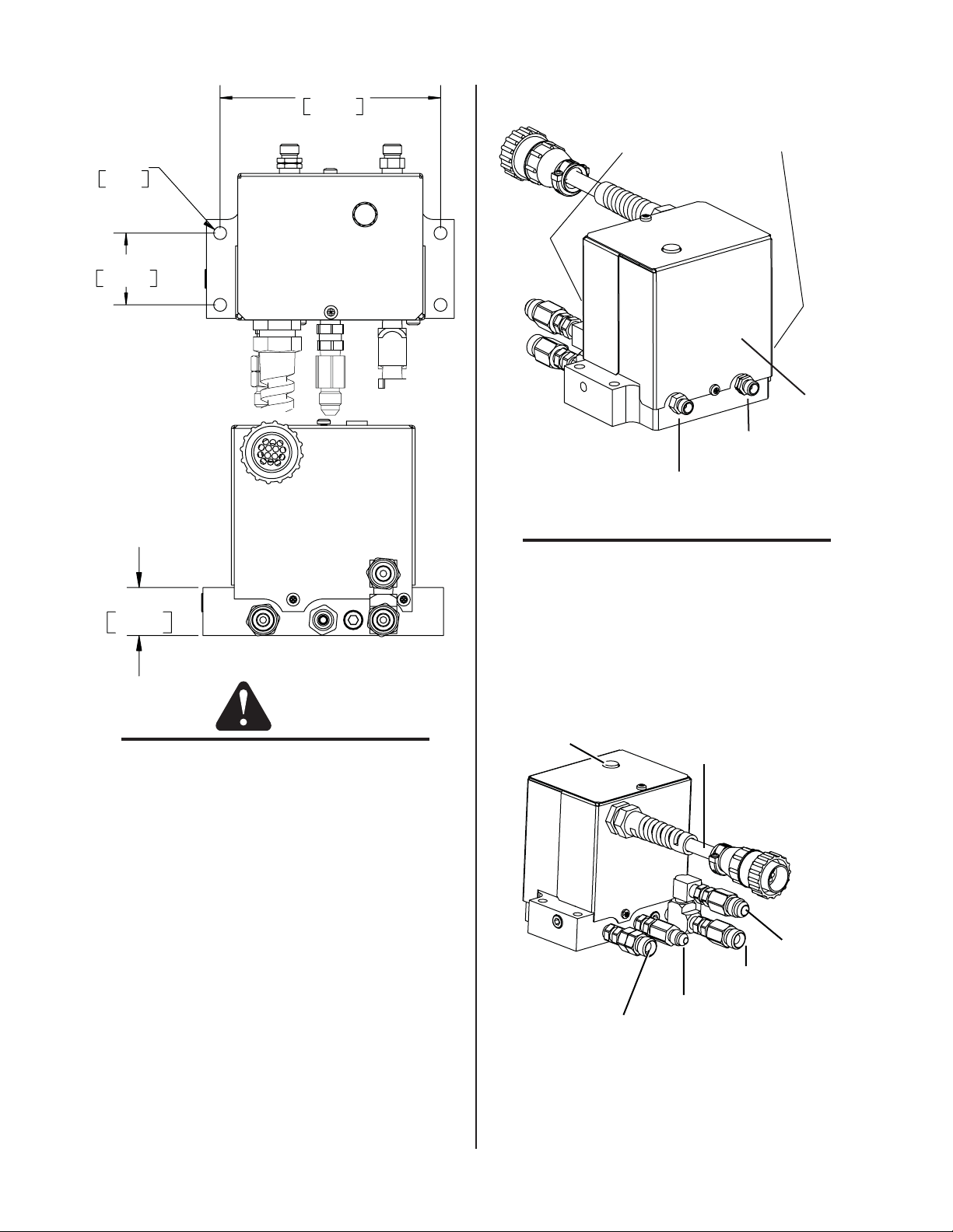
4.450 in.
113.03 mm
2. Connect the Valve Kit outlets to the torch leads as
shown.
.261 in Dia.
6.63 mm
1.450 in
36.83 mm
Art # A-07648
1.00 in.
25.40 mm
CAUTION
Place one wrench on the TVA fi tting and keep
it from turning before tightening or loosening
any hose fi ttings.
Art # A-07649
Do not remove brass plugs
Front and side
Outlet Side
Art # A-07645
Left-hand Thread:
To Torch Plasma Gas fitting
Right-hand Thread:
To Torch Shield Gas fitting
NOTE
Two 4’ hoses are provided in this kit. They
MUST be used if the existing hoses leak, have
any damage to them or are less than 4’ in
length. Do not use hoses that are not 4’ long.
3. Connect the gas supply lines and the control cable
connector from the Gas Control Module to the Valve
Kit as shown. Hold the check valves stationary while
attaching the gas lines.
Exhaust Muffler
Control Cable
Do not remove brass plugs from base.
February 5, 2007
WMS™ Inl
Shield Gas Inlet
Preflow Gas Inlet
Plasma Gas Inlet
2
Manual 0-4964 Rev AA.01
Art # A-07646
Page 3

4. Once all connections have been made, a careful check
m
of all fi ttings for leaks and function needs to be made. Use
a standard leak detection or soap based liquid to test for
leaks. Turn the system on and check setting displays for
each of the gasses.
Control Connector Pinout Diagram
2: To SOL16 (Btm)
1: To SOL16 (Top)
5: To SOL14 (Top)
& SOL18
8: To SOL15 (Top)
& SOL19
9: To SOL15 (Btm)
& SOL19
4
3: Ground
12
6: To SOL14 (Bt
& SOL18
7
11
10
14
13
WARNINGS
Disconnect primary power at the source before
starting the procedure.
Use caution when handling the printed circuit
board as damage can result from improper
handling or from electrostatic discharge. Wear
appropriate static-handling equipment and
grounding strap while performing this replacement procedure.
1. Remove the screws securing the cover panel to the gas
control module. Save the hardware for re-use.
2. Carefully remove the cover from the module noting
the attached ground wire. Remove the ground wire if
needed.
SOL15
SOL16
SOL19
SOL18
Fuse Update on Main PCB in GCM 2010
NOTE
Depending on version at time of purchase
or other updates some GCM 2010 units may
not need to have the fuses updated. It will be
necessary to verify this. One way to do that is
by removing the cover and inspecting the two
fuses at F14 and F15. The following explains
how to do that and update the two fuses.
SOL14
Gas Control Module Cover
Remove Ground
Wire
Do not remove
Art # A-07647
Art # A-06882
February 5, 2007
3. Locate the Main PCB mounted on the left side panel.
Remove the multi pin harness from the upper right at
J13.
3
Manual 0-4964 Rev AA.01
Page 4

4. Locate fuses at F14 and F15 shown below.
Art # A-07652
F15
J13
F14
New Fuse
Rating Label
Fuses F14 and F15 are
250V and .0250A
NOTE
Check the values of these fuses. If the fuses are
the same as those provided in this kit do not
replace them and go to step 7.
5. If the fuses at F14 and F15 are not 250VAC .0250A,
replace them with two of the four provided in this kit.
The other two are extra and should be saved for possible future use along with the two being removed. Do
not use the fuses in this kit in any other location on
this PCB.
February 5, 2007
6. Locate the new Fuse Rating Label supplied in this kit
and where it is to be applied shown above. Before applying the new Fuse Rating Label on the PCB ,clean
the surface using a clean cloth. If cleaning solution
is needed it must be approved for use on and around
electrical components. Once the surface is clean and
dry, apply the label.
7. Reconnect the harness plug to J13 and replace the
cover with the ground wire attached.
4
Manual 0-4964 Rev AA.01
Page 5

DIP Switch Selection
8. Locate the C.C.M. style in (with or without external box) that applies and SW13 as indicated in the following illustrations. Set the SW13 switches accordingly.
SW11
SW6
SW12
SW13
SW13: TVA and XTL Switch positions
1
2
TVA XTL-TVA
SW13
1
2
No external
connection cover
Art # A-07672
February 5, 2007
5
Manual 0-4964 Rev AA.01
Page 6

SW6
SW12
SW11
SW13
SW13: TVA and XTL Switch positions
TVA XTL-TVA
1
2
SW13
1
2
Art # A-07671
9. This ends the installation instructions for the XTL Torch Valve Assembly Kit.
NOTE
Operation of the Torch Valve is controlled by the Gas Control Module. The Torch Valve does not require
any adjustment or calibration.
NOTE
Every effort has been made to provide complete and accurate information in this manual. However,
the publisher does not assume and hereby disclaims any liability to any party for any loss or damage
caused by errors or omissions in this Manual, whether such errors result from negligence, accident, or
any other cause.
February 5, 2007
6
Manual 0-4964 Rev AA.01
 Loading...