

Page 1
Art # A-09778
35
AMP
1
PHASE
DC
35A
™
CUTSKILL
PLASMA CUTTING SYSTEM
Operating Manual
Rev. AA Issue Date: January 7, 2011 Manual # 0-5180
Operating Features:
Page 2

WE APPRECIATE YOUR BUSINESS!
Congratulations on your new Thermal Dynamics product. We are proud to
have you as our customer and will strive to provide you with the best service
and reliability in the industry. This product is backed by our extensive war
ranty and world-wide service network. To locate your nearest distributor
or service provider visit us on the web
(Americas and Europe).
This Operating Manual has been designed to instruct you on the correct
use and operation of your Thermal Dynamics product. Your satisfaction
with this product and its safe operation is our ultimate concern. There
fore please take the time to read the entire manual, especially the Safety
Precautions. They will help you to avoid potential hazards that may exist
when working with this product.
at www.thermal-dynamics.com
YOU ARE IN GOOD COMPANY!
The Brand of Choice for Contractors and Fabricators Worldwide.
-
-
Thermal Dynamics is a Global Brand of manual and automation Plasma
Cutting Products for Thermadyne Industries Inc.
We distinguish ourselves from our competition through market-leading,
dependable products that have stood the test of time. We pride ourselves
on technical innovation, competitive prices, excellent delivery, superior
customer service and technical support, together with excellence in sales
and marketing expertise.
Above all, we are committed to developing technologically advanced
products to achieve a safer working environment within the welding
industry.
Page 3

!
Read and understand this entire Manual and your employer’s safety practices before installing,
operating, or servicing the equipment.
While the information contained in this Manual represents the Manufacturer's best judgement, the
Manufacturer assumes no liability for its use.
Plasma Cutting Power Supply
CutSkill™ 35A
SL40 1Torch™
Operating Manual Number 0-5180
Published by:
Thermal Dynamics Corporation
82 Benning Street
West Lebanon, New Hampshire, USA 03784
(603) 298-5711
www.thermal-dynamics.com
Copyright 2011 by
Thermadyne Corporation
WARNINGS
All rights reserved.
Reproduction of this work, in whole or in part, without written permission of the publisher is
prohibited.
The publisher does not assume and hereby disclaims any liability to any party for any loss or
damage caused by any error or omission in this Manual, whether such error results from negligence, accident, or any other cause.
Publication Date: January 7, 2011
Record the following information for Warranty purposes:
Where Purchased:_______________________________ ____________
Purchase Date:__________________________________ ____________
Power Supply Serial #:___________________________ _____________
Torch Serial #:___________________________________ ___________
Page 4

TABLE OF CONTENTS
SECTION 1:GENERAL INFORMATION ........................................................................................................ 1-1
1.01 Notes, Cautions and Warnings ................................................................................. 1-1
1.02 Important Safety Precautions ...................................................................................1-1
1.03 Publications .............................................................................................................. 1-3
1.04 Declaration of Conformity......................................................................................... 1-4
1.05 Statement of Warranty .............................................................................................1-5
SECTION 2 SYSTEM:INTRODUCTION ...................................................................................................... 2-1
2.01 Working Principle .....................................................................................................
2.02 Power Supply Specifications ....................................................................................
2.03 Input Wiring Specifications ...................................................................................... 2-2
2.04 Power Supply Features ............................................................................................. 2-3
SECTION 2TORCH:INTRODUCTION .......................................................................................................
2T.01 Scope of Manual
2T.02 Specifications ........................................................................................................ 2T-1
2T.03 Introduction to Plasma ........................................................................................... 2T-2
SECTION 3:INSTALLATION ....................................................................................................................... 3-1
3.01 Unpacking ................................................................................................................ 3-1
3.02 Lifting Options .......................................................................................................... 3-1
3.03 Primary Input Power Connections ............................................................................ 3-1
3.04 Air Supply Connections ............................................................................................ 3-2
SECTION 4 SYSTEM:OPERATION .............................................................................................................. 4-1
4.01 Control Panel ............................................................................................................
4.02 Preparations For Operating....................................................................................... 4-2
4.03 Sequence of Operation ............................................................................................. 4-5
4.04 Cut Quality ................................................................................................................ 4-7
4.05 General Cutting Information ..................................................................................... 4-8
..................................................................................................... 2T-1
2-1
2-1
2T-1
4-1
SECTION 5 SYSTEM: SERVICE .................................................................................................................
5.01 General Maintenance ................................................................................................ 5-1
5.02 Basic Troubleshooting Guide .................................................................................... 5-2
SECTION 5 TORCH:SERVICE ................................................................................................................... 5T-1
5T.01 General Maintenance .............................................................................................. 5T-1
5T.02 Inspection and Replacement of Consumable Torch Parts ....................................... 5T-1
SECTION 6:PARTS LISTS ..........................................................................................................................
6.01 Introduction .............................................................................................................. 6-1
6.02 Ordering Information ................................................................................................ 6-1
APPENDIX 1:CIRCUIT DIAGRAM .............................................................................................................A-1
GLOBAL CUSTOMER SERVICE CONTACT INFORMATION ............................................................ Rear Cover
5-1
6-1
Page 5
cutskill 35A
!
!
SECTION 1:
GENERAL INFORMATION
1.01 Notes, Cautions and Warnings
Throughout this manual, notes, cautions, and warnings are used to
highlight important information. These highlights are categorized as
follows:
NOTE
An operation, procedure, or background information
which requires additional emphasis or is helpful in ef
ficient operation of the system.
CAUTION
A procedure which, if not properly followed, may cause
damage to the equipment.
A procedure which, if not properly followed, may cause
injury to the operator or others in the operating area.
WARNING
-
or welding any metals which may contain one or more of the
following:
Antimony Chromium Mercury
Arsenic Cobalt Nickel
Barium Copper Selenium
Beryllium Lead Silver
Cadmium Manganese Vanadium
• Always read the Material Safety Data Sheets (MSDS) that should
be supplied with the material you are using. These MSDSs
will give you the information regarding the kind and amount of
fumes and gases that may be dangerous to your health.
• For information on how to test for fumes and gases in your
workplace, refer to item 1 in Subsection 1.03, Publications in
this manual.
• Use special equipment, such as water or down draft cutting
tables, to capture fumes and gases.
• Do not use the plasma torch in an area where combustible or
explosive gases or materials are located.
• Phosgene, a toxic gas, is generated from the vapors of chlo
rinated solvents and cleansers. Remove all sources of these
vapors.
• This product, when used for welding or cutting, produces
fumes or gases which contain chemicals known to the State
of California to cause birth defects and, in some cases, cancer.
(California Health & Safety Code Sec. 25249.5 et seq.)
-
1.02 Important Safety Precautions
WARNING
OPERATION AND MAINTENANCE OF PLASMA ARC
EQUIPMENT CAN BE DANGEROUS AND HAZARDOUS
TO YOUR HEALTH.
Plasma arc cutting produces intense electric and magnet
ic emissions that may interfere with the proper function
of cardiac pacemakers, hearing aids, or other electronic
health equipment. Persons who work near plasma arc
cutting applications should consult their medical health
professional and the manufacturer of the health equipment to determine whether a hazard exists.
To prevent possible injury, read, understand and follow
all warnings, safety precautions and instructions before
using the equipment. Call 1-603-298-5711 or your local
distributor if you have any questions.
GASES AND FUMES
Gases and fumes produced during the plasma cutting process can be
dangerous and hazardous to your health.
• Keep all fumes and gases from the breathing area. Keep your
head out of the welding fume plume.
• Use an air-supplied respirator if ventilation is not adequate to
remove all fumes and gases.
• The kinds of fumes and gases from the plasma arc depend on
the kind of metal being used, coatings on the metal, and the
different processes. You must be very careful when cutting
-
Electric Shock can injure or kill. The plasma arc process uses and
produces high voltage electrical energy. This electric energy can cause
severe or fatal shock to the operator or others in the workplace.
Fire and explosion can be caused by hot slag, sparks, or the plasma
arc.
ELECTRIC SHOCK
• Never touch any parts that are electrically “live” or “hot.”
• Wear dry gloves and clothing. Insulate yourself from the work
piece or other parts of the welding circuit.
• Repair or replace all worn or damaged parts.
• Extra care must be taken when the workplace is moist or
damp.
• Install and maintain equipment according to NEC code, refer to
item 9 in Subsection 1.03, Publications.
• Disconnect power source before performing any service or
repairs.
• Read and follow all the instructions in the Operating Manual.
FIRE AND EXPLOSION
• Be sure there is no combustible or flammable material in the
workplace. Any material that cannot be removed must be
protected.
• Ventilate all flammable or explosive vapors from the work
place.
• Do not cut or weld on containers that may have held combus
tibles.
• Provide a fire watch when working in an area where fire hazards
may exist.
Manual 0-5180 1-1 GENERAL INFORMATION
-
-
Page 6
cutskill 35A
Pb!
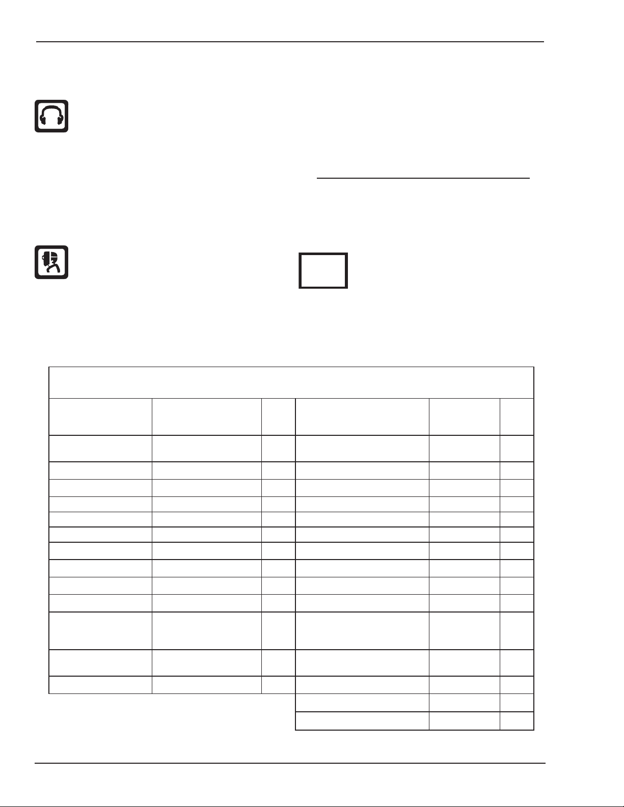
Eye protection filter shade selector for welding or cutting
(goggles or helmet), from AWS A6.2-73.
Welding or Cutting
Operation
Electrode Size
Metal Thickness
Filter
Shade
Welding or Cutting
Operation
Electrode Size
Metal Thickness
Filter
Shade
Torch soldering 2
Gas metal-arc
welding (MIG)
Torch brazing 3 or 4 Non-ferrous base metal All 11
Oxygen Cutting Non-ferrous base metal All 12
Light Under 1 in., 25 mm 3 or 4 Gas tungsten arc welding All 12
Medium 1 to 6 in., 25-150 mm 4 or 5 (TIG) All 12
Heavy Over 6 in., 150 mm 5 or 6 Atomic hydrogen welding All 12
Gas welding Carbon arc welding All 12
Light Under 1/8 in., 3 mm 4 or 5 Plasma arc welding
Medium 1/8 to 1/2 in., 3-12 mm 5 or 6 Carbon arc air gouging
Heavy Over 1/2 in., 12 mm 6 or 8 Light 12
Shielded metal-arc
welding
(stick) electrodes
Under 5/32 in., 4 mm 10 Heavy 14
5/32 to 1/4 in.,
4 to 6.4 mm
12 Plasma arc cutting
Over 1/4 in., 6.4 mm 14 Light Under 300 Amp 9
Medium 300 to 400 Amp 12
Heavy Over 400 Amp 14
• Hydrogen gas may be formed and trapped under aluminum
workpieces when they are cut underwater or while using a water
table. DO NOT cut aluminum alloys underwater or on a water
table unless the hydrogen gas can be eliminated or dissipated.
Trapped hydrogen gas that is ignited will cause an explosion.
NOISE
Noise can cause permanent hearing loss. Plasma arc processes can
cause noise levels to exceed safe limits. You must protect your ears
from loud noise to prevent permanent loss of hearing.
• To protect your hearing from loud noise, wear protective ear
plugs and/or ear muffs. Protect others in the workplace.
• Noise levels should be measured to be sure the decibels (sound)
do not exceed safe levels.
• For information on how to test for noise, see item 1 in Subsec
tion 1.03, Publications, in this manual.
PLASMA ARC RAYS
Plasma Arc Rays can injure your eyes and burn your skin. The plasma
arc process produces very bright ultra violet and infrared light. These
arc rays will damage your eyes and burn your skin if you are not
properly protected.
• To protect your eyes, always wear a welding helmet or shield.
Also always wear safety glasses with side shields, goggles or
other protective eye wear.
• Wear welding gloves and suitable clothing to protect your skin
from the arc rays and sparks.
• Keep helmet and safety glasses in good condition. Replace
lenses when cracked, chipped or dirty.
• Protect others in the work area from the arc rays. Use protective
booths, screens or shields.
• Use the shade of lens as suggested in the following per ANSI/
ASC Z49.1:
Minimum Protective Suggested
Arc Current Shade No. Shade No.
Less Than 300* 8 9
300 - 400* 9 12
400 - 800* 10 14
*These values apply where the actual arc is clearly
-
seen. Experience has shown that lighter filters may
be used when the arc is hidden by the workpiece.
LEAD WARNING
This product contains chemicals, including lead, or otherwise produces
chemicals known to the State of California to cause cancer, birth defects
and other reproductive harm. Wash hands after handling. (California
Health & Safety Code § 25249.5 et seq.)
GENERAL INFORMATON 1-2 Manual 0-5180
Table 1-1
Page 7

cutskill 35A
1.03 Publications
Refer to the following standards or their latest revisions for more
information:
1. OSHA, SAFETY AND HEALTH STANDARDS, 29CFR 1910,
obtainable from the Superintendent of Documents, U.S.
Government Printing Office, Washington, D.C. 20402
2. ANSI Standard Z49.1, SAFETY IN WELDING AND CUTTING,
obtainable from the American Welding Society, 550 N.W.
LeJeune Rd, Miami, FL 33126
3. NIOSH, SAFETY AND HEALTH IN ARC WELDING AND GAS
WELDING AND CUTTING, obtainable from the Superintendent
of Documents, U.S. Government Printing Office, Washington,
D.C. 20402
4. ANSI Standard Z87.1, SAFE PRACTICES FOR OCCUPATION
AND EDUCATIONAL EYE AND FACE PROTECTION, obtainable
from American National Standards Institute, 1430 Broadway,
New York, NY 10018
5. ANSI Standard Z41.1, STANDARD FOR MEN’S SAFETY-TOE
FOOTWEAR, obtainable from the American National Standards
Institute, 1430 Broadway, New York, NY 10018
6. ANSI Standard Z49.2,
TING AND WELDING PROCESSES, obtainable from American
National Standards Institute, 1430 Broadway, New York, NY
10018
7. AWS Standard A6.0,
ERS WHICH HAVE HELD COMBUSTIBLES, obtainable from
American Welding Society, 550 N.W. LeJeune Rd, Miami, FL
33126
8. NFPA Standard 51, OXYGEN-FUEL GAS SYSTEMS FOR WELD
ING, CUTTING AND ALLIED PROCESSES, obtainable from
the National Fire Protection Association, Batterymarch Park,
Quincy, MA 02269
FIRE PREVENTION IN THE USE OF CUT-
WELDING AND CUTTING CONTAIN-
9. NFPA Standard 70, NATIONAL ELECTRICAL CODE, obtainable
from the National Fire Protection Association, Batterymarch
Park, Quincy, MA 02269
10. NFPA Standard 51B, CUTTING AND WELDING PROCESSES,
obtainable from the National Fire Protection Association, Bat
terymarch Park, Quincy, MA 02269
11. CGA Pamphlet P-1, SAFE HANDLING OF COMPRESSED
GASES IN CYLINDERS, obtainable from the Compressed
Gas Association, 1235 Jefferson Davis Highway, Suite 501,
Arlington, VA 22202
12. CSA Standard W117.2, CODE FOR SAFETY IN WELDING
AND CUTTING, obtainable from the Canadian Standards As
sociation, Standards Sales, 178 Rexdale Boulevard, Rexdale,
Ontario, Canada M9W 1R3
13. NWSA booklet, WELDING SAFETY BIBLIOGRAPHY obtainable
from the National Welding Supply Association, 1900 Arch
Street, Philadelphia, PA 19103
14. American Welding Society Standard AWSF4.1, RECOM
MENDED SAFE PRACTICES FOR THE PREPARATION FOR
WELDING AND CUTTING OF CONTAINERS AND PIPING THAT
HAVE HELD HAZARDOUS SUBSTANCES, obtainable from the
American Welding Society, 550 N.W. LeJeune Rd, Miami, FL
33126
15. ANSI Standard Z88.2, PRACTICE FOR RESPIRATORY PRO
TECTION, obtainable from American National Standards
Institute, 1430 Broadway, New York, NY 10018
16. Safety in Welding and Allied Processes Part 2: Electrical,
AS1674.2-2007 from SAI Global Limited, www.saiglobal.
com
-
-
-
-
-
Manual 0-5180 1-3 GENERAL INFORMATION
Page 8

cutskill 35A
S
1.04 Declaration of Conformity
Manufacturer: Thermadyne Company
Address: 82 Benning Street
West Lebanon, New Hampshire 03784
USA
The equipment described in this manual conforms to all applicable aspects and regulations of the ‘Low Voltage Directive’ (European Council Directive
73/23/EEC as amended by Council Directive 93/68/EEC) and to the National legislation for the enforcement of this Directive.
The equipment described in this manual conforms to all applicable aspects and regulations of the "EMC Directive" (European Council Directive
89/336/EEC) and to the National legislation for the enforcement of this Directive.
Serial numbers are unique with each individual piece of equipment and details description, parts used to manufacture a unit and date of manufacture.
National Standard and Technical Specifications
The product is designed and manufactured to a number of standards and technical requirements. Among them are:
* CSA (Canadian Standards Association) standard C22.2 number 60 for Arc welding equipment.
* UL (Underwriters Laboratory) rating 94VO flammability testing for all printed-circuit boards used.
* CENELEC EN50199 EMC Product Standard for Arc Welding Equipment.
* ISO/IEC 60974-1 (BS 638-PT10) (EN 60 974-1) (EN50192) (EN50078) applicable to plasma cutting equipment and associated accessories.
* AS60974.1 Arc Welding Equipment Welding Power Sources.
For environments with increased hazard of electrical shock, Power Supplies bearing the
conjunction with hand torches with exposed cutting tips, if equipped with properly installed standoff guides.
* Extensive product design verification is conducted at the manufacturing facility as part of the routine design and manufacturing process.
This is to ensure the product is safe, when used according to instructions in this manual and related industry standards, and performs as
specified. Rigorous testing is incorporated into the manufacturing process to ensure the manufactured product meets or exceeds all design
specifications.
Thermadyne has been manufacturing products for more than 30 years, and will continue to achieve excellence in our area of manufacture.
Manufacturers responsible representative in Europe: Steve Ward
Thermadyne Europe
Europa Building
Chorley N Industrial Park
Chorley, Lancashire,
England PR6 7BX
Operations Director
mark conform to EN50192 when used in
GENERAL INFORMATON 1-4 Manual 0-5180
Page 9

cutskill 35A
1.05 Statement of Warranty
LIMITED WARRANTY: Subject to the terms and conditions established below, Thermadyne Company warrants to the original retail purchaser that new
Thermal Dynamics CUTSKILL™ plasma cutting systems sold after the effective date of this warranty are free of defects in material and workmanship.
Should any failure to conform to this warranty appear within the applicable period stated below, Thermadyne Company shall, upon notification thereof and
substantiation that the product has been stored operated and maintained in accordance with Thermadyne’s specifications, instructions, recommendations
and recognized industry practice, correct such defects by suitable repair or replacement.
This warranty is exclusive and in lieu of any warranty of merchantability or fitness for a particular purpose.
Thermadyne will repair or replace, at its discretion, any warranted parts or components that fail due to defects in material or workmanship within the
time periods set out below. Thermadyne Company must be notified within 30 days of any failure, at which time Thermadyne Company will provide
instructions on the warranty procedures to be implemented.
Thermadyne Company will honor warranty claims submitted within the warranty periods listed below. All warranty periods begin on the date of sale
of the product to the original retail customer or 1 year after sale to an authorized Thermadyne Distributor.
LIMITED WARRANTY PERIOD
Product
Power Supply Components
(Parts and Labor)
Torch and Leads
(Parts and Labor)
CUTSKILL 35A 2 Year 1 Year
This warranty does not apply to:
1. Consumable Parts, such as tips, electrodes, shield cups, o - rings, starter cartridges, gas distributors, fuses, filters.
2. Equipment that has been modified by an unauthorized party, improperly installed, improperly operated or misused based upon industry standards.
In the event of a claim under this warranty, the remedies shall be, at the discretion of Thermadyne Company:
1. Repair of the defective product.
2. Replacement of the defective product.
3. Reimbursement of reasonable costs of repair when authorized in advance by Thermadyne.
4. Payment of credit up to the purchase price less reasonable depreciation based on actual use.
These remedies may be authorized by Thermadyne and are FOB West Lebanon, NH or an authorized Thermadyne service station. Product returned
for service is at the owner’s expense and no reimbursement of travel or transportation is authorized.
LIMITATION OF LIABILITY: Thermadyne Company shall not under any circumstances be liable for special or consequential damages such as, but not
limited to, damage or loss of purchased or replacement goods or claims of customer of distributors (hereinafter “Purchaser”) for service interruption.
The remedies of the Purchaser set forth herein are exclusive and the liability of Thermadyne with respect to any contract, or anything done in
connection therewith such as the performance or breach thereof, or from the manufacture, sale, delivery, resale, or use of the goods covered by or
furnished by Thermadyne whether arising out of contract, negligence, strict tort, or under any warranty, or otherwise, shall not, except as expressly
provided herein, exceed the price of the goods upon which liability is based.
This warranty becomes invalid if replacement parts or accessories are used which may impair the safety or performance of any Thermadyne
product.
This warranty is invalid if the Thermal Dynamics product is sold by non - authorized persons.
Effective December 10, 2010
Manual 0-5180 1-5 GENERAL INFORMATION
Page 10

Page 11
SECTION 2 SYSTEM:
Rectifier
Inverter
Transformer
Rectifier
Reduce pressure, filter
Gas valve Cutting torch
Workpiece
Compressed air
Art # A-09204_AB
INTRODUCTION
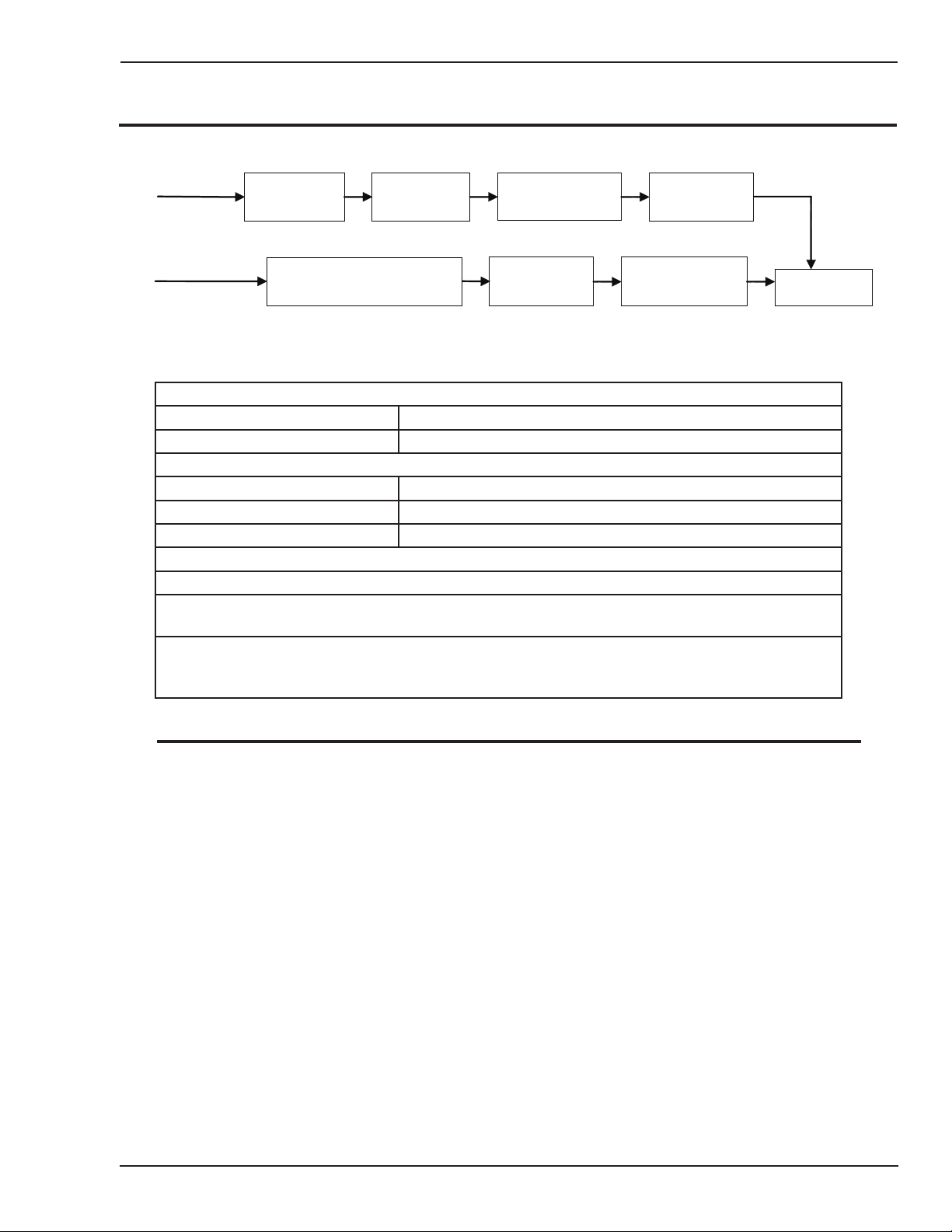
2.01 Working Principle
2.02 Power Supply Specifications
CutSkill 35A Power Supply Specifications
Input Power 230 VAC (± 15%), Single-Phase, 50 Hz
Output Current 15-35 Amps, continuously variable
CutSkill 35A Power Supply Duty Cycle (Note 1)
Ambient Temperature 104° F (40° C)
Duty Cycle
Current 35 Amps
SL 40 Torch Gas Requirements (see section 2T.03)
1. Duty Cycle is the percentage of time the system can be operated without overheating. Duty cycle is re
duced if primary input voltage (AC) is low or the DC voltage is higher than shown in this chart.
2. Air supply must be free of oil, moisture, and other contaminants. Excessive oil and moisture may cause
double-arcing, rapid tip wear, or even complete torch failure. Contaminants may cause poor cutting perfor
mance and rapid electrode wear. Optional filters provide increased filtering capabilities.
30%
Notes
NOTE
cutskill 35A
-
-
IEC Rating is determined as specified by the International Electro-Technical Commission. These specifica
tions include calculating an output voltage based upon power supply rated current. To facilitate comparison
between power supplies, all manufacturers use this output voltage to determine duty cycle.
TDC Rating is determined using an output voltage representative of actual output voltage during cutting
with a TDC torch. This voltage may be more or less than IEC voltage, depending upon choice of torch,
consumables, and actual cutting operation.
Manual 0-5180 2-1 INTRODUCTION
Page 12
cutskill 35A
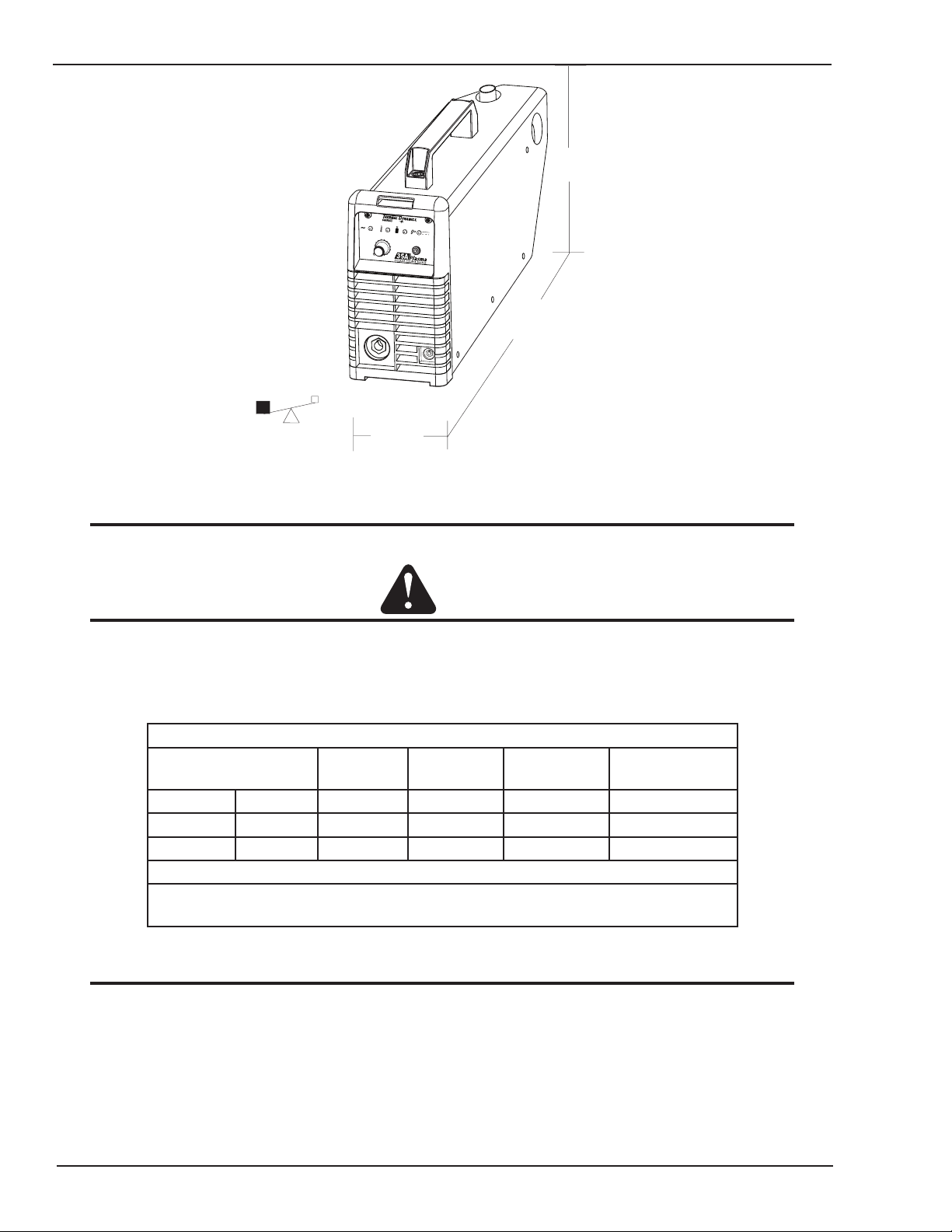
26lb / 11.8kg
5 1/4"
133 mm
16 1/2"
419 mm
R
U
N
S
E
T
C
U
R
R
E
N
T
(
A
)
2
5
3
5
R
E
A
D
Y
A
I
R
O
V
E
R
H
E
A
T
P
O
W
E
R
11"
280 mm
Art # A-09174
Figure 2-1 Power Supply Dimensions & Weight
NOTE
Weight includes torch & leads, input power cord, and work cable with clamp.
CAUTION
Provide clearance for proper air flow through the power supply. Operation without proper air flow will
inhibit proper cooling and reduce duty cycle.
2.03 Input Wiring Specifications
CutSkill 35A Input Power Requirements
Input Power Input Current Input Current Input
Voltage Freq. (kVA) Max (Amps) Ieff (Amps) Fuse (Amps)
(Volts) (Hz) 1-Ph 1-Ph 1-Ph 1-Ph
230 50 3.4 27.3 14 16
Line Voltages with Suggested Circuit Protection.
Motor start fuses or thermal circuit breakers are recommended for this application. Check
local requirements for your situation in this regard.
NOTE
Refer to Local and National Codes or local authority having jurisdiction for proper wiring requirements.
Cable size is de-rated based on the Duty Cycle of the equipment.
The suggested sizes are based on flexible power cable with power plug installations.
Suggested Sizes
(See Note)
Cable conductor temperature used is 167° F (75° C).
INTRODUCTION 2-2 Manual 0-5180
Page 13

2.04 Power Supply Features
Gas Pressure Regulator/
Filter Assembly
Control Panel
Torch Lead
R
U
N
SE
T
C
U
R
R
E
N
T
(A
)
25
35
R
E
A
D
Y
A
IR
O
V
E
RH
E
A
T
P
O
WE
R
230V AC Power Source
Work Cable and Clamp
Art # A-09779
Gas Pressure Regulator/
Filter Assembly
Gas Pressure Gauge
Art # A-09176
cutskill 35A
Manual 0-5180 2-3 INTRODUCTION
Page 14

This Page left blank intentionally.
Page 15

cutskill 35A
8.3" (210.82mm)
2.6"
(66.04mm)
.96" (24.38mm)
Art # A-09336
!
SECTION 2TORCH:
INTRODUCTION
2T.01 Scope of Manual
This manual contains descriptions, operating instructions and maintenance procedures for the SL40 Plasma
Cutting Torch. Service of this equipment is restricted to
properly trained personnel; unqualified personnel are
strictly cautioned against attempting repairs or adjust
ments not covered in this manual, at the risk of voiding
the Warranty. Read this manual thoroughly. A complete
understanding of the characteristics and capabilities of
this equipment will assure the dependable operation for
which it was designed.
2T.02 Specifications
A. Torch Configurations
1. Hand Torch, Model SL40
The hand torch head is at 75° to the torch handle.
The hand torches include a torch handle and torch
trigger assembly.
F. Torch Ratings
Ambient
Temperature
Duty Cycle 100% @ 40 Amps @ 193 scfh
Maximum Current 40 Amps
Voltage (V
Arc Striking Voltage
-
G. Current Ratings
SL40 Torch & Leads
Power Supply characteristics will determine
material thickness range.
H. Gas Requirements
SL40 Torch Gas Specications
Gas (Plasma and Secondary) Compressed Air
SL40 Torch Ratings
) 500V
peak
SL40 Current Ratings
Up to 40 Amps, DC,
Straight Polarity
NOTE
104° F
40° C
500V
B. Torch Leads Lengths
Hand Torches are available as follows:
• 15 ft / 4.6 m.
C. Torch Parts
Starter Cartridge, Electrode, Tip, Shield Cup
D. Parts - In - Place (PIP)
Torch has built-in switch.
12 vdc circuit rating
E. Type Cooling
Combination of ambient air and gas stream through
torch.
Minimum Input Pressure
Maximum Input Pressure 125 psi / 8.6 bar
Gas Flow
WARNING
75 psi
5.2 bar
193 scfh
91 lpm
This torch is not to be used with oxygen (O2).
This torch is not to be use with high frequency
starting systems.
Manual 0-5180 2T-1 INTRODUCTION
Page 16

CUTSKILL 35A
A-00002
Workpiece
Power
Supply
+
_
C
B
A
Torch Trigge
r
PIP Switch
Shield Cup
To Control
Cable Wiring
Torch Switch
A-09595
2T.03 Introduction to Plasma
A. Plasma Gas Flow
Plasma is a gas which has been heated to an extremely
high temperature and ionized so that it becomes electri
cally conductive. The plasma arc cutting and gouging
processes use this plasma to transfer an electrical arc
to the workpiece. The metal to be cut or removed is
melted by the heat of the arc and then blown away.
While the goal of plasma arc cutting is separation of
the material, plasma arc gouging is used to remove
metals to a controlled depth and width.
In a Plasma Cutting Torch a cool gas enters Zone B,
where a arc between the electrode and the torch tip
heats and ionizes the gas. The main cutting arc then
transfers to the workpiece through the column of
plasma gas in Zone C.
By forcing the plasma gas and electric arc through a
small orifice, the torch delivers a high concentration
of heat to a small area. The stiff, constricted plasma
arc is shown in Zone C. Direct current (DC) straight
polarity is used for plasma cutting, as shown in the
illustration.
Zone A channels a secondary gas that cools the torch.
This gas also assists the high velocity plasma gas in
blowing the molten metal out of the cut allowing for a
fast, slag - free cut.
B. Gas Distribution
The single gas used is internally split into plasma and
secondary gases.
-
The plasma gas flows into the torch through the
negative lead, through the starter cartridge, around
the electrode, and out through the tip orifice.
The secondary gas flows down around the outside
of the torch starter cartridge, and out between the tip
and shield cup around the plasma arc.
C. Pilot Arc
When the torch is started a pilot arc is established
between the electrode and cutting tip. This pilot
arc creates a path for the main arc to transfer to the
work.
D. Main Cutting Arc
DC power is also used for the main cutting arc. The
negative output is connected to the torch electrode
through the torch lead. The positive output is con
nected to the workpiece via the work cable and to the
torch through a pilot wire.
E. Parts - In - Place (PIP)
The torch includes a 'Parts - In - Place' (PIP) circuit.
When the shield cup is properly installed, it closes
a switch. The torch will not operate if this switch is
open.
-
INTRODUCTION 2T-2 Manual 0-5180
Typical Torch Head Detail
Parts - In - Place Circuit Diagram for Hand Torch
Page 17

cutskill 35A
!
SECTION 3:
INSTALLATION
3.01 Unpacking
1. Use the packing lists to identify and account for each item.
A. Contents List
Description Quantity
Power source 1
3 m power input cable (fitted) 1
SL40 (fitted) 1
Work cable and clamp (fitted) 1
Carry case 1
35 A Drag Tip (Located in power source handle) 2
Electrode (Located in power source handle) 1
Gas Regulator 1
Operating Manual 1
2. Inspect each item for possible shipping damage. If damage is evident, contact your distributor and / or shipping
company before proceeding with the installation.
3. Record Power Supply and Torch model and serial numbers, purchase date and vendor name, in the information
block at the front of this manual.
3.02 Lifting Options
The Power Supply includes a handle for hand lifting only. Be sure unit is lifted and transported safely and securely.
Do not touch live electrical parts.
Disconnect input power cord before moving unit.
FALLING EQUIPMENT can cause serious personal injury and can damage equipment.
HANDLE is not for mechanical lifting.
• Only persons of adequate physical strength should lift the unit.
• Lift unit by the handle, using two hands. Do not use straps for lifting.
• Use optional cart or similar device of adequate capacity to move unit.
• Place unit on a proper skid and secure in place before transporting with a fork lift or other vehicle.
WARNING
3.03 Primary Input Power Connections
CAUTION
Check your power source for correct voltage before plugging in or connecting the unit. The primary power
source, fuse, and any extension cords used must conform to local electrical code and the recommended
circuit protection and wiring requirements as specified in Section
Manual 0-5180 3-1 INSTALLATION
2.
Page 18

cutskill 35A
Art # A-09781
230V AC Power Source
Power Cord and Plug
This power supply comes installed with a input power cable with no plug, Single - Phase input power.
Figure 3-1 230V AC Power Source
When the power source input voltage is over or under the safe operating range, the alarm light will turn on, at the
same time the current output will be cut off.
If the power supply voltage continually goes beyond the safe work voltage range it will shorten the power source
life-span.
3.04 Air Supply Connections
A. Connecting Air Supply to Unit
The connection is the same for compressed air or industrial compressed air in gas cylinders.
1. Connect the gas line to the compressed air input inlet port at the appropriate pressure. The illustration shows
typical fittings as an example. (Minimum pressure should be 75 psi/5.2 bar)
For a secure seal, apply thread sealant to the fitting threads, according to manufacturer's instructions. Do
Not use Teflon tape as a thread sealer, as small particles of the tape may break off and block the small gas
passages in the torch.
NOTE
INSTALLATION 3-2 Manual 0-5180
Page 19

cutskill 35A
Gas Supply Hose
Adjustment knob
of compressed
air Pressure
Compressed air
pressure meter
Air filter
Compressed
air input
Art # A-09178
Hose Clamp
Fitting
Figure 3-2 Gas Connection to Compressed Air input
B. Using Industrial Compressed Air In Gas Cylinders
When using Industrial compressed air in gas cylinders as the gas supply:
1. Refer to the manufacturer’s specifications for installation and maintenance procedures for high pressure gas
regulators.
2. Examine the cylinder valves to be sure they are clean and free of oil, grease or any foreign material. Briefly open
each cylinder valve to blow out any dust which may be present.
3. The cylinder must be equipped with an adjustable high - pressure regulator capable of outlet pressures up to 100
psi (6.9 bar) maximum and flows of at least 193 scfh (91 lpm).
4. Connect gas supply hose to the cylinder.
NOTE
Pressure should be set at 75 psi (5.2 bar) at the high pressure gas cylinder regulator.
Supply hose must be at least 1/4 inch (6 mm) I.D.
For a secure seal, apply thread sealant to the fitting threads, according to manufacturer's instructions. Do
Not use Teflon tape as a thread sealer, as small particles of the tape may break off and block the small gas
passages in the torch.
Manual 0-5180 3-3 INSTALLATION
Page 20

This page left blank intentionally.
Page 21

4.01 Control Panel
RUN
SET
CURREN T (A)
15
25
35
READY
AIR
OVERHE AT
POWER
Cutting Current Control
Work Lead Connection
Power On Indicator
Torch Connection
Run/Set Switch
Over Heat Indicator
Air Indicator
DC Indicator
Art # A-09179
Adjustment knob
of compressed
air Pressure
Power switch
Compressed air
pressure meter
Power cable
input
Air filter
Compressed
air input
Art # A-09180
cutskill 35A
SECTION 4 SYSTEM:
OPERATION
The Front Panel The Rear Panel
1. ON / OFF Switch (Power Switch)
Controls input power to the power supply. I is ON, O is OFF.
2. RUN / SET Switch
RUN (up) position is for general torch operation. SET (down) position is for setting gas pressure and purging
lines.
3. (A) Output Current Control
Sets the desired output current. If the overload protection (fuse or circuit breaker) on the input power circuit
opens frequently, either reduce cutting output, reduce the cutting time, or connect the unit to more adequate
input power. Refer to Section 2 for input power requirements.
4.
Power ON Indicator (AC Indicator)
Steady light indicates power supply is ready for operation.
5.
OVERHEAT Indicator (TEMP Indicator)
Indicator is normally OFF. Indicator is ON when internal temperature exceeds normal limits. Allow the unit to
run with the fan on until the temp indicator turns off.
6.
AIR Indicator
AIR light should be ON when there is insufficient gas pressure (below 50 psi).
7.
READY (DC Indicator)
Indicator is ON when DC output circuit is active.
Manual 0-5180 4-1 OPERATION
Page 22

cutskill 35A
!
Art # A-09793_AC
Start Cartridge,
Cat. No. 9-0097
Electrode, Cat. No. 9-0096
Worn Electrode
Worn Tip
35 Amp Drag Tip, Cat. No. 9-0091
Shield Cup, Cat. No. 9-0098
8. Parts - in - place ( PIP)
This unit is fitted with a protective interlock mode (parts in place sensor), which serves to protect the user from
potentially dangerous voltages when changing consumables. If the shield cup is not correctly fitted, the output
will be disabled and the air indicator will flash.
NOTE
All consumables must be correctly fitted and maintained to ensure correct operation.
4.02 Preparations For Operating
At the start of each operating session:
WARNING
Disconnect primary power at the source before assembling or disassembling power supply, torch parts,
or torch and leads assemblies.
A. Torch Parts Selection
Check the torch for proper assembly and appropriate torch parts. The torch parts must correspond with the type
of operation, and with the amperage output of this power supply (35 amps maximum). Use only genuine Thermal
Dynamics parts with this torch.
OPERATION 4-2 Manual 0-5180
Page 23

cutskill 35A
Art # A-03387
Art # A-09181
RU N
SE T
CU RR EN T (A)
15
25
35
RE AD Y
AI R OV ER HE AT
PO WE R
NOTE
When operating the torch in a normal condition, a small amount of gas vents through the gap between
the shield cup and torch handle. Do not attempt to over tighten the shield cup as irreparable damage to
internal components may result.
B. Torch Connection
Check that the torch is properly connected.
C. Check Primary Input Power Source
1. Check the power source for proper input voltage. Make sure the input power source meets the power require
ments for the unit per Section 2, Specifications.
2. Connect the input power cable (or close the main disconnect switch) to supply power to the system.
D. Gas Selection
Ensure gas source meets requirements listed in section 2T. Check connections and turn gas supply on.
E. Connect Work Cable
Clamp the work cable to the workpiece or cutting table. The area must be free from oil, paint and rust. Connect
only to the main part of the workpiece; do not connect to the part to be cut off.
-
F. Power On
Place the power supply ON / OFF switch to the ON (I) position. Power indicator
turns on.
Front Panel With Power ON/OFF Indicator
Manual 0-5180 4-3 OPERATION
Page 24

cutskill 35A
Gas Pressure Regulator/
Filter Assembly
Gas Pressure Gauge
Art # A-09176
Art # A-09181
RU N
SE T
CU RR EN T (A)
15
25
35
RE AD Y
AI R OV ER HE AT
PO WE R
G. Set Operating Pressure
Place the power supply RUN / SET switch to the SET (down) position. Gas will flow. Adjust gas pressure to 65
psi / 4.5 bar. Air indicator
turns on.
NOTE
If gas regulator leaks, reset gas pressure to 0 psi, then reset to 65 psi / 4.5 bar.
H. Select Current Output Level
Place RUN / SET switch to RUN (up) position. Gas flow will stop. Set the desired current output level.
OPERATION 4-4 Manual 0-5180
Page 25

cutskill 35A
A-00024_AB
Shield Cup
Torch
Standoff Distance
1/8" - 3/8" (3 - 9mm)
Art # A-09342
Trigger
Trigger Release
3
4
Trigger
2
1
Trigger Release
Art# A-09341
4.03 Sequence of Operation
The following is a typical sequence of operation for this
power supply. Refer to Appendix 1 for block diagram.
1. Plug the input power cord into an active circuit.
a. AC power is available at the power supply.
2. Place the ON / OFF switch on the power supply
to ON (up) position.
a. AC indicator turns on; fan turns on.
NOTE
Gas will automatically flow from torch for 4
seconds, this is a safety circuit that makes
sure the torch tip is properly installed.
3. Set gas pressure.
a. Turn gas pressure adjustment knob to set
pressure to 75 psi / 5.2 bar.
NOTE
Minimum pressure for power supply opera
tion is lower than minimum pressure for torch
operation.
4. Wear protective clothing, including welding gloves
and appropriate eye protection (see table 1-1).
Place tip on work piece and pull trigger. Arc will
initiate and start cutting material.
• Standoff Cutting With Hand Torch
NOTE
-
b). For standoff cutting, hold the
torch tip on the work piece, pull the trigger.
After the arc is initiated lift the tip to 1/8"
- 3/8" (3-4mm) off the work.
Standoff Distance
For best performance and parts life, always use
the correct parts for the type of operation.
A. The torch can be comfortably held in one hand
or steadied with two hands. Position the hand
to press the Trigger on the torch handle. With
the hand torch, the hand may be positioned
close to the torch head for maximum control
or near the back end for maximum heat protection. Choose the holding technique that feels
most comfortable and allows good control
and movement.
NOTE
The tip should never come in contact with the
workpiece except during drag cutting opera
-
tions.
B. Depending on the cutting operation, do one
of the following:
a). For edge starts, hold the torch
perpendicular to the workpiece with the
front of the tip on the edge of the workpiece
at the point where the cut is to start.
C. Cut as usual. Simply release the trigger
assembly to stop cutting.
Manual 0-5180 4-5 OPERATION
Page 26

cutskill 35A
Shield Cup
Workpiece
Standoff Guide
Art # A-09790
Art # A-09342
Trigger
Trigger Release
3
4
Trigger
2
1
Trigger Release
Art# A-09341
D. Follow normal recommended cutting practices
as provided in the power supply operating
manual.
NOTE
When the shield cup is properly installed, there
is a slight gap between the shield cup and the
torch handle. Gas vents through this gap as
part of normal operation. Do not attempt to
force the shield cup to close this gap. Forcing
the shield cup against the torch head or torch
handle can damage components.
E. For a consistent standoff height from the
workpiece, install the standoff guide by sliding
it onto the torch shield cup. Install the guide
with the legs at the sides of the shield cup
body to maintain good visibility of the cutting
arc. During operation, position the legs of the
standoff guide against the workpiece.
C. Keep the torch in contact with the workpiece
during the cutting cycle.
D. Hold the torch away from your body.
E. Slide the trigger release toward the back of the
torch handle while simultaneously squeezing
the trigger. The arc will start.
F. Place the torch tip on the work. The main arc
will transfer to the work.
NOTE
The gas preflow and postflow are a character
istic of the power supply and not a function
of the torch.
• Drag Cutting With a Hand Torch
Drag cutting works best on metal 1/4"(6 mm) thick
or less.
NOTE
For best parts performance and life, always
use the correct parts for the type of opera
-
tion.
A. Install the drag cutting tip and set the output
G. Cut as usual. Simply release the trigger as-
sembly to stop cutting.
H. Follow normal recommended cutting practices
as provided in the power supply operating
manual.
5. Complete cutting operation.
NOTE
current.
B. The torch can be comfortably held in one hand
or steadied with two hands. Position the hand
to press the Trigger on the torch handle. With
the hand torch, the hand may be positioned
close to the torch head for maximum control
or near the back end for maximum heat protection. Choose the holding technique that feels
most comfortable and allows good control and
movement.
If the torch is lifted too far from the workpiece
while cutting, the main arc will stop and the
pilot arc will automatically restart.
OPERATION 4-6 Manual 0-5180
-
Page 27

6. Release the torch trigger.
Kerf Width
Cut Surface
Bevel Angle
Top Edge
Rounding
Cut Surface
Drag Lines
Dross
Build-Up
Top
Spatter
A-00007
a. Main arc stops.
7. Set the power supply ON / OFF switch to OFF
(down position).
a. AC indicator
turns OFF.
8. Set the main power disconnect to OFF, or unplug
input power cord.
a. Input power is removed from the system.
4.04 Cut Quality
NOTE
Cut quality depends heavily on setup and
parameters such as torch standoff, alignment
with the workpiece, cutting speed, gas pres
sures, and operator ability.
cutskill 35A
Nitride Build - Up
Nitride deposits can be left on the surface of the cut
when nitrogen is present in the plasma gas stream.
These buildups may create difficulties if the material
is to be welded after the cutting process.
Bevel Angle
The angle between the surface of the cut edge and
a plane perpendicular to the surface of the plate. A
perfectly perpendicular cut would result in a 0° bevel
angle.
Top - Edge Rounding
Rounding on the top edge of a cut due to wearing
-
from the initial contact of the plasma arc on the
workpiece.
Refer to appendix pages for additional infor
-
mation as related to the power supply used.
Cut quality requirements differ depending on application.
For instance, nitride build - up and bevel angle may be
major factors when the surface will be welded after cut
ting. Dross - free cutting is important when finish cut
quality is desired to avoid a secondary cleaning operation.
The following cut quality characteristics are illustrated in
the following figure:
Bottom Dross Buildup
Molten material which is not blown out of the cut area
and resolidifies on the plate. Excessive dross may
require secondary cleanup operations after cutting.
-
Kerf Width
The width of the cut (or the width of material removed
during the cut).
Top Spatter (Dross)
Top spatter or dross on the top of the cut caused by
slow travel speed, excess cutting height, or cutting
tip whose orifice has become elongated.
Cut Quality Characteristics
Cut Surface
The desired or specified condition (smooth or rough)
of the face of the cut.
Manual 0-5180 4-7 OPERATION
Page 28

cutskill 35A
!
Right Side
Cut Angle
Left Side
Cut Angle
A-00512
4.05 General Cutting Information
WARNING
Disconnect primary power at the source be
fore disassembling the power supply, torch,
or torch leads.
Frequently review the Important Safety Pre
cautions at the front of this manual. Be sure
the operator is equipped with proper gloves,
clothing, eye and ear protection. Make sure
no part of the operator’s body comes into
contact with the workpiece while the torch is
activated.\
CAUTION
Sparks from the cutting process can cause
damage to coated, painted, and other surfaces
such as glass, plastic and metal.
NOTE
Handle torch leads with care and protect them
from damage.
Torch Standoff
Improper standoff (the distance between the torch tip
and workpiece) can adversely affect tip life as well as
shield cup life. Standoff may also significantly affect
the bevel angle. Reducing standoff will generally
result in a more square cut.
Edge Starting
-
-
Side Characteristics Of Cut
To make a square - edged cut along an inside diameter
of a circle, the torch should move counterclockwise
around the circle. To keep the square edge along
an outside diameter cut, the torch should travel in a
clockwise direction.
Dross
When dross is present on carbon steel, it is com
monly referred to as either “high speed, slow speed,
or top dross”. Dross present on top of the plate is
normally caused by too great a torch to plate distance.
"Top dross" is normally very easy to remove and can
often be wiped off with a welding glove. "Slow speed
dross" is normally present on the bottom edge of the
plate. It can vary from a light to heavy bead, but does
not adhere tightly to the cut edge, and can be easily
scraped off. "High speed dross" usually forms a narrow bead along the bottom of the cut edge and is very
difficult to remove. When cutting a troublesome steel,
it is sometimes useful to reduce the cutting speed to
produce "slow speed dross". Any resultant cleanup
can be accomplished by scraping, not grinding.
-
For edge starts, hold the torch perpendicular to the
workpiece with the front of the tip near (not touching)
the edge of the workpiece at the point where the cut
is to start. When starting at the edge of the plate, do
not pause at the edge and force the arc to "reach" for
the edge of the metal. Establish the cutting arc as
quickly as possible.
Direction of Cut
In the torches, the plasma gas stream swirls as it
leaves the torch to maintain a smooth column of
gas. This swirl effect results in one side of a cut
being more square than the other. Viewed along the
direction of travel, the right side of the cut is more
square than the left.
OPERATION 4-8 Manual 0-5180
Page 29

SECTION 5 SYSTEM: SERVICE
Warning!
There are extremely dangerous voltage and power levels present inside
this product. Do not attempt to open or repair unless you are a qualified
electrical tradesperson and you have had training in power measurements
and troubleshooting techniques. If major complex subassemblies are faulty,
then the Cutting Power Source must be returned to an Thermadyne for
repair.
Each Use
Visual check of
torch tip and electrode
Weekly
Visually inspect the torch body tip,
electrode, start cartridge and shield cup
Visually inspect the
cables and leads.
Replace as needed
3 Months
6 Months
Replace all
broken parts
Visually check and
Carefully clean the
interior
Maintain more often
if used under severe
conditions
Art # A-00004
R
U
N
S
E
T
C
U
R
R
E
N
T
(
A
)
2
5
3
5
R
E
A
D
Y
A
I
R
O
V
E
R
H
E
A
T
P
O
W
E
R
Clean
exterior
of power supply
R
U
N
S
E
T
C
U
R
R
E
N
T
(
A
)
2
5
3
5
R
E
A
D
Y
A
I
R
O
V
E
R
H
E
A
T
P
O
W
E
R
5.01 General Maintenance
cutskill 35A
Manual 0-5180 5-1 SERVICE
Page 30

cutskill 35A
!
A. Every three months
Check external air filter, replace if necessary.
1. Shut off input power; turn off the gas supply.
sary.
Leave internal ground wire in place.
B. Every six months
1. Check the in-line air filter(s), clean or replace as required.
2. Check cables and hoses for leaks or cracks, replace if necessary.
3. Check all contactor points for severe arcing or pits, replace if necessary.
4. Vacuum dust and dirt out of the entire machine.
Bleed down the gas supply. Check air filter and replace if neces-
NOTE
5.02 Basic Troubleshooting Guide
WARNING
There are extremely dangerous voltage and power levels present inside this unit. Do not attempt to diagnose
or repair it unless you are an accredited service provider and you have had training in power electronics
measurement and troubleshooting techniques.
1. Common Faults symptom
A. Gas regulator leakage
1) Gas regulator on
a. Reset the regulator to 0 PSI and re-adjust it to 75 PSI (5.2 bar).
B. AC indicator
1) Main input power cord does not connect to power distribution net.
a. Connect the power cord.
2) Power ON/OFF switch in OFF (down) position.
a. Turn switch to ON (up) position.
3) Actual input voltage does not correspond to voltage of unit.
a. Verify that the input line voltage is correct.
4) Faulty components in unit
a. Return for repair or have qualified technician repair per service manual.
C. Torch will not pilot; When trigger is activated, Air indicator
1) Gas pressure too low. Adjust the pressure to 75 PSI/5.2 bar.
D. AC indicator ON, TEMP indicator
1) Air flow blocked
a. Check for blocked air flow around the unit and correct condition.
2) Fan blocked
a. Check for blocked status and correct condition.
OFF
ON.
ON.
SERVICE 5-2 Manual 0-5180
Page 31

cutskill 35A
3) Unit is overheated.
a. Keep the machine plugged in and turned on for five minutes. This will allow
the fan to run and cool the machine.
4) Faulty components in unit
a. Return for repair or have qualified technician repair per service manual.
E. Torch will not pilot, when torch trigger is activated.
1) The system is in SET mode.
a. Switch to RUN mode.
2) Faulty parts in torch
a. Check torch parts per section 4.02; replace as needed.
3) Gas pressure too high or too low
a. Adjust pressure to proper setting value.
4) Faulty components in unit
a. Return for repair or have qualified technician repair per service manual.
F. No cutting output when torch is activated; AC indicator
1) Torch is not connected properly to power supply.
a. Check torch connection to power supply.
2) Working cable not connected to work piece, or connection is poor.
a. Make sure that work cable has a proper connection to a clean, dry area of the
work piece.
3) Faulty components in unit
a. Return for repair or have qualified technician repair per service manual.
4) Faulty torch
a. Return for repair or have qualified technician repair.
G. Torch cuts but not adequately
1) Incorrect setting of output current control
a. Check and adjust to proper setting.
2) Working cable connection to work piece is poor.
a. Make sure that work cable has a proper connection to a clean, dry area of the
work piece.
3) Faulty components in unit
a. Return for repair or have qualified technician repair.
H. Output is restricted, and can not be controlled.
1) Input or output connection is poor.
a. Check all input and output connection leads.
2) Working cable connection to work piece is poor.
a. Make sure that work cable has a proper connection to a clean, dry area of the
work piece.
3) Faulty components in unit
a. Return for repair or have qualified technician repair per service manual.
I. Cutting output is unstable or inadequate.
1) Input or output connection is poor
a. Check all input and output connection leads.
ON, gas flows, fan turns.
Manual 0-5180 5-3 SERVICE
Page 32

cutskill 35A
2) Working cable connection is poor.
a. Make sure that work cable has a proper connection to a clean, dry area of the
work piece.
3) Fluctuations in input power
a. Have electrician check input line voltage.
J. Hard to startup
1) Torch parts worn (consumables)
a. Turn off input power, remove shield cup, tip, start cartridge, and electrode
and check them all. If the electrode or cutting tip is worn out, replace them.
If the start cartridge does not move freely, replace it. If there is too much spat ter on shield cup, replace it.
K. Arc goes out while operating. Arc can’t be restarted when torch trigger is activated.
1) Power Supply is overheated (TEMP indicator
a. Let unit cool down for at least 5 minutes. Make sure the unit has not been
operated beyond duty cycle limit.
2) Fan blades blocked (TEMP indicator
a. Check and clear blades.
3) Air flow blocked
a. Check for blocked air flow around the unit and correct condition.
4) Gas pressure is too low. (Air indicator
a. Check gas source, It should be set to at least 75 PSI/5.2 bar. Adjust it as
needed.
5) Torch parts worn
a. Check torch shield cup, cutting tip, start cartridge and electrode. Replace as
needed.
6) Faulty component in unit
a. Return for repair or have qualified technician repair per service manual.
L. Torch cuts but not well.
1) Current control is set too low.
a. Increase the current setting.
2) Torch is being moved too fast across work piece
a. Reduce cutting speed.
3) Excessive oil or moisture in torch
a. Hold torch 1/8 inch (3 mm) from clean surface while purging and observe
oil or moisture buildup (do not activate torch). If there are contaminants in the
gas, additional filtering may be needed.
ON).
ON).
ON when torch trigger is activated.)
SERVICE 5-4 Manual 0-5180
Page 33

cutskill 35A
Art# A-09345
Electrode
Start Cartridge
Tip
Shield Cup
Torch Head
Good Tip
Worn Tip
A-09791
SECTION 5 TORCH:
SERVICE
5T.01 General Maintenance
NOTE
Refer to Previous "Section 5 System" for com
mon and fault indicator descriptions.
Cleaning Torch
Even if precautions are taken to use only clean air with
a torch, eventually the inside of the torch becomes
coated with residue. This buildup can affect the arc
initiation and the overall cut quality of the torch.
WARNING
Disconnect primary power to the system be
fore disassembling the torch or torch leads.
Remove the consumable torch parts as follows:
NOTE
The shield cup holds the tip and starter car
tridge shield cup in place. Position the torch
with the shield cup facing upward to prevent
these parts from falling out when the cup is
removed.
-
1. Unscrew and remove the shield cup from the
torch.
NOTE
Slag built up on the shield cup that cannot
be removed may effect the performance of
the system.
2. Inspect the cup for damage. Wipe it clean or
replace if damaged.
-
DO NOT touch any internal torch parts while
the AC indicator light of the Power Supply is
ON.
The inside of the torch should be cleaned with electrical contact cleaner using a cotton swab or soft wet
rag. In severe cases, the torch can be removed from
the leads and cleaned more thoroughly by pouring
electrical contact cleaner into the torch and blowing
it through with compressed air.
CAUTION
Dry the torch thoroughly before reinstalling..
5T.02 Inspection and Replacement of
Consumable Torch Parts
WARNING
Disconnect primary power to the system be
fore disassembling the torch or torch leads.
DO NOT touch any internal torch parts while
the AC indicator light of the Power Supply is
ON.
Consumable Parts
3. Remove the tip. Check for excessive wear (indicated by an elongated or oversized orifice). Clean
or replace the tip if necessary.
-
Tip Wear
Manual 0-5180 5T-1 SERVICE
Page 34

cutskill 35A
Art A-09792
Worn Electrode
New Electrode
Art # A-09346
Art# A-09817
Electrode
Start Cartridge
Tip
Shield Cup
Torch Head
1
2
3
4
4. Remove the starter cartridge. Check for excessive
wear, plugged gas holes, or discoloration. Check
the lower end fitting for free motion. Replace if
necessary.
5. Pull the electrode straight out of the torch head.
Check the face of the electrode for excessive wear.
Refer to the following figure.
SL40 Replacement Parts
Item # Description Cat. No
1 Electrode 9-0096
2 Start Cartridge 9-0097
3 Tip, 20-35A Drag 9-0091
4 Shield Cup 9-0098
N/S SL40 Torch w/ 15ft (4.6m) leads 7-0041
6. Reinstall the electrode by pushing it straight into
7. Reinstall the desired starter cartridge and tip into
8. Hand tighten the shield cup until it is seated on the
Electrode Wear
the torch head until it clicks.
the torch head.
torch head. If resistance is felt when installing the
cup, check the threads before proceeding.
SERVICE 5T-2 Manual 0-5180
Page 35

SECTION 6:
1
3
4
2
5
Art # A-09930
6
7
8
9
10
11
PARTS LISTS
6.01 Introduction
A. Parts List Breakdown
The parts list provides a breakdown of all replaceable components.
Item # Qty Description Catalog #
1 1 Logic PCB assembly 9-0134
2 1 Control PCB assembly
3 1 Main PCB assembly 9-0137
4 1 Regulator 9-0139
5 1 Solenoid assembly 9-0140
6 1 Pressure Switch 9-0136
7 1 Current Transformer 9-0138
8 1 CS35 Machine Cover 9-0376
9 1 CS35 Front Panel 9-0377
10 1 CS35 Rear Panel 9-0378
11 1 CS35 Fan 9-0381
9-0135
cutskill 35a
B. Returns
If a product must be returned for service, contact your distributor. Materials returned without proper authorization
will not be accepted.
Manual 0-5180 6-1 PART LIST
Page 36

This page left blank intentionally.
Page 37

603-298-5711
THERMAL DYNAMICS
INDUSTRIAL OARK NO.2
WEST LEBANON,NH 03784
A THERMADYNE Company
Information proprietary to THERMAL DYNAMICS CORPORATION
Not for Release Reproduction or Distribution without written consent
NOTE:
Unless otherwise Specified resistors are in Ohms 1/4W 5%
Capacitors are in Microfarads (UF)
TITLE:
SCHEMATIC
35A 240V SINGLE PHASE 50/60 Hz
Date
By
Rev Revision
PILOT
WORK
T
ORC
H
WV OUTPUT
BLACK
RED
FAN
DC24V
AC240V
INPUT 50/60 Hz
AC240V
D & T
WV OUTPUT
FEEDBACK SIGNAL
N/A
DRIVE
POWER
OT
AIR
READY
CURRENT CONTROL
SET / RUN
DRIVE SIGNAL
N/A
SOURCE&TIP
SIGNAL
HF&QF
GAS SOLENOID
TEST
TORCH SW
PRESSURE SW
OVER TEMPERATURE
1
2
3
1
2
3
1
2
1
234
1
2
3
4
1
2
3
4
5
1
2
3
4
5
6
7
1
2
1
2
3
4
1
2
1
2
3
1
2
3
4
5
6
1
2
3
1
2
3
4
1
2
1
2
3
4
5
1
2
3
4
5
6
7
1
2
SW
1
2
3
+
-
+
-
+
+
Art # A-09193_AC
APPENDIX 1:
CIRCUIT DIAGRAM
cutskill 35a
Manual 0-5180 A-1 APPENDIX
Page 38

This page left blank intentionally.
Page 39

This Page Intentionally Blank.
Page 40

&ORª5SEªWITHª%UROPEANª,ITERATUREªLARGEªAREAªªªª
7 / 2 , $ ª ( % ! $ 1 5 ! 2 4 % 2 3 ª ª ª 3 W I N G L E Y ª 2 I D G Eª 2 O A D ª 3 U IT E ª ª ª s ª ª 3 T ª ,O U I S ª - I S S OU R I ª ª ª 5 3 !
A Global Cutting & Welding Market Leader
™
Customer Care UK: +44 (0)1257 261 755 / Fax: +44 (0)1257 224 800
Customer Care Italy +39 02 36546801 / Fax: +39 02 36546480
www.thermadyne.com
Denton, TX USA
U.S. Customer Care
*\Ê £nää{ÓÈ£nnnÊÌvÀii®
>Ý\Ê£nääxÎxäxxÇÊÌvÀii®
International Customer Care
*\Ê £{äÎn££Ó£Ó
>Ý\Ê£{ä{nÎn£Çn
Miami, FL USA
Sales Office, Latin America
*\Ê £x{ÇÓÇnÎÇ£
>Ý\Ê£x{ÇÓÇnÎÇÈ
Oakville, Ontario, Canada
Canada Customer Care
*\Ê £äxnÓÇ{x£x
>Ý\Ê£nääxnn£Ç£{ÊÌvÀii®
Chorley, United Kingdom
Customer Care
*\Ê ³{{Ê£ÓxÇÓÈ£Çxx
>Ý\ʳ{{Ê£ÓxÇÓÓ{nää
Milan, Italy
Customer Care
*\К ³ОКдУОИx{Иnд£
>Э\К³ОКдУОИx{Иn{д
Cikarang, Indonesia
Customer Care
*\К ИУУ£nдИдx
>Э\ККИУУ£nдИдИ
Rawang, Malaysia
Customer Care
*\К ³ИдОКИдУУnn
>Э\К³ИдОКИдУ£дnx
Melbourne, Australia
Australia Customer Care
*\Ê £ÎääÈx{ÈÇ{ÊÌvÀii®
*\Ê È£Î{Ç{Ç{ääÊ
>Ý\ÊÈ£Î{Ç{ÇΣ
International
*\Ê È£Î{Ç{Çxän
>Ý\ÊÈ£Î{Ç{Ç{nn
Shanghai, China
Sales Office
*\К ³nИКУ£И{дЗУИУИ
>Э\КК³nИКУ£И{{nОдОУ
Singapore
Sales Office
*\К ³ИxКИnОУnдИИ
>Э\К³ИxКИЗИОxn£У
&ORMª.OªXXªªªªªÊ ^ÊÓä£äÊ/iÀ>`ÞiÊ`ÕÃÌÀiÃ]ÊV°Ê ÜÜÜ°ÌiÀ>`Þi°VÊ *ÀÌi`ÊÊ1°-°°
THE AMERICAS EUROPE ASIA/PACIFIC
 Loading...