

Page 1
LIQUID COOLED
PLASMA TORCH
Model Maximizer 300
For Use With:
• Merlin 15XC Cutting Systems
Instruction Manual
December 1, 2003 Manual No. 0-2554
Page 2

Page 3

WARNINGS
Read and understand this entire Manual and your employer’s safety practices before installing, operating, or servicing the equipment.
While the information contained in this Manual represents the Manufacturer's best judgement, the
Manufacturer assumes no liability for its use.
Liquid Cooled Plasma Torch
Model Maximizer 300 Used With Merlin15XC System
Instruction Manual No. 0-2554
Published by:
Thermal Dynamics Corporation
82 Benning Street
West Lebanon, New Hampshire, USA 03784
(603) 298-5711
www.thermal-dynamics.com
Copyright 1996 by
Thermal Dynamics Corporation
All rights reserved.
Reproduction of this work, in whole or in part, without written permission of the publisher is prohibited.
The publisher does not assume and hereby disclaims any liability to
any party for any loss or damage caused by any error or omission in
this Manual, whether such error results from negligence, accident, or
any other cause.
Printed in the United States of America
Publication Date: December 1, 2003
Record the following information for W arranty purposes:
Where Purchased: _______________________________________
Purchase Date: _______________________________________
Power Supply Serial #: _______________________________________
Torch Serial #: _______________________________________
Page 4

TABLE OF CONTENTS
SECTION 1:
GENERAL INFORMATION ............................................................................................... 1-1
1.01 Notes, Cautions and W arnings ..................................................................... 1-1
1.02 Important Safety Precautions ....................................................................... 1-1
1.03 Publications.................................................................................................. 1-2
1.04 Note, Attention et Avertissement .................................................................. 1-3
1.05 Precautions De Securite Importantes........................................................... 1-3
1.06 Documents De Reference ............................................................................ 1-5
1.07 Declaration of Conformity ............................................................................. 1-7
1.08 Statement of Warranty.................................................................................. 1-8
SECTION 2:
INTRODUCTION .............................................................................................................. 2-1
2.01 Scope of Manual .......................................................................................... 2-1
2.02 General Description ..................................................................................... 2-1
2.03 Specifications & Design Features................................................................. 2-1
2.04 Options And Accessories ............................................................................. 2-2
2.05 Introduction to Plasma.................................................................................. 2-3
SECTION 3:
INSTALLATION ................................................................................................................. 3-1
3.01 Introduction .................................................................................................. 3-1
3.02 Site Location ................................................................................................ 3-1
3.03 Unpacking .................................................................................................... 3-1
3.04 Setting Up Machine Torch ............................................................................ 3-1
3.05 Connecting Torch ......................................................................................... 3-2
3.06 Gas Selection............................................................................................... 3-2
3.07 Gas Connection ........................................................................................... 3-4
SECTION 4:
OPERATION ..................................................................................................................... 4-1
4.01 Introduction ................................................................................................. 4-1
4.02 Functional Overview..................................................................................... 4-1
4.03 Getting Started............................................................................................. 4-1
4.04 Torch Parts Selection ................................................................................... 4-2
4.05 Cut Quality ................................................................................................... 4-3
4.06 Operating the System .................................................................................. 4-4
4.07 Machine Torch Oper ation ............................................................................. 4-5
4.08 Recommended Cutting Speeds.................................................................... 4-7
4.09 Gouging ....................................................................................................... 4-7
Page 5

TABLE OF CONTENTS (continued)
SECTION 5:
SERVICE .......................................................................................................................... 5-1
5.01 Introduction .................................................................................................. 5-1
5.02 General Torch Maintenance ......................................................................... 5-1
5.03 Common Operating Faults ........................................................................... 5-2
5.04 Inspection and Replacement Consumable Torch Parts ................................ 5-2
5.05 Troubleshooting Guide ................................................................................. 5-4
5.06 Servicing Machine Torch Components ......................................................... 5-5
5.07 T orch & Leads Troubleshooting .................................................................... 5-6
SECTION 6:
PARTS LISTS.................................................................................................................... 6-1
6.01 Introduction ................................................................................................. 6-1
6.02 Ordering Information ................................................................................... 6-1
6.03 Replacement Machine Torch P arts.............................................................. 6-2
6.04 Torch Consumables ..................................................................................... 6-4
6.05 Complete Assembly Replacements............................................................. 6-6
6.06 Torch Options And Accessories................................................................... 6-6
APPENDIX 1: SEQ UENCE OF OPERATION BLOCK DIAGRAM.............................................A-1
APPENDIX 2: CUTTING SPEED CHAR TS FOR MERLIN 15XC SYSTEMS............................A-2
APPENDIX 3: GAS FLO W COMPARISON CHART................................................................. A-24
Page 6

Page 7
SECTION 1:
GENERAL INFORMATION
1.01 Notes, Cautions and Warnings
Throughout this manual, notes, cautions, and warnings
are used to highlight important information. These highlights are categorized as follows:
NOTE
An operation, procedure, or backgr ound information which requires additional emphasis or is helpful in efficient operation of the system.
CAUTION
A procedure which, if not properly followed, may
cause damage to the equipment.
WARNING
A procedure which, if not properly followed, may
cause injury to the operator or others in the operating area.
1.02 Important Safety Precautions
WARNINGS
OPERATION AND MAINTENANCE OF
PLASMA ARC EQUIPMENT CAN BE DANGEROUS AND HAZARDOUS TO YOUR
HEAL TH.
Plasma arc cutting produces intense electric and
magnetic emissions that may interfere with the
proper function of cardiac pacemakers, hearing
aids, or other electronic health equipment. Persons who work near plasma arc cutting applications should consult their medical health professional and the manufacturer of the health
equipment to determine whether a hazard exists.
To prevent possible injury, read, understand and
follow all warnings, safety precautions and instructions before using the equipment. Call 1-603298-5711 or your local distributor if you have any
questions.
GASES AND FUMES
Gases and fumes produced during the plasma cutting
process can be dangerous and hazardous to your health.
• Keep all fumes and gases from the breathing area.
Keep your head out of the welding fume plume.
• Use an air-supplied respirator if ventilation is not
adequate to remove all fumes and gases.
• The kinds of fumes and gases from the plasma arc
depend on the kind of metal being used, coatings
on the metal, and the different pr ocesses. Y ou must
be very careful when cutting or welding any metals which may contain one or more of the following:
Antimony Chromium Mercury
Arsenic Cobalt Nickel
Barium Copper Selenium
Beryllium Lead Silver
Cadmium Manganese Vanadium
• Always read the Material Safety Data Sheets
(MSDS) that should be supplied with the material
you are using. These MSDSs will give you the information regarding the kind and amount of fumes
and gases that may be dangerous to your health.
• For information on how to test for fumes and gases
in your workplace, refer to item 1 in Subsection 1.03,
Publications in this manual.
• Use special equipment, such as water or down draft
cutting tables, to capture fumes and gases.
• Do not use the plasma torch in an area where combustible or explosive gases or materials are located.
• Phosgene, a toxic gas, is generated from the vapors
of chlorinated solvents and cleansers. Remove all
sources of these vapors.
• This product, when used for welding or cutting,
produces fumes or gases which contain chemicals
known to the State of California to cause birth defects and, in some cases, cancer . (California Health
& Safety Code Sec. 25249.5 et seq.)
ELECTRIC SHOCK
Electric Shock can injure or kill. The plasma arc process
uses and produces high voltage electrical energy. This
electric energy can cause severe or fatal shock to the operator or others in the workplace.
• Never touch any parts that are electrically “live”
or “hot.”
Date: No v ember 15, 2001 1-1 GENERAL INFORMATION
Page 8
• Wear dry gloves and clothing. Insulate yourself
from the work piece or other parts of the welding
circuit.
• Repair or replace all worn or damaged parts.
• Extra care must be taken when the workplace is
moist or damp.
• Install and maintain equipment according to NEC
code, refer to item 9 in Subsection 1.03, Publications.
• Disconnect power source before performing any
service or repairs.
• Read and follow all the instructions in the Operating Manual.
FIRE AND EXPLOSION
Fire and explosion can be caused by hot slag, sparks, or
the plasma arc.
• Be sure there is no combustible or flammable material in the workplace. Any material that cannot
be removed must be protected.
• Ventilate all flammable or explosive vapors from
the workplace.
• Do not cut or weld on containers that may have
held combustibles.
• Provide a fire watch when working in an area wher e
fire hazards may exist.
• Hydrogen gas may be formed and trapped under
aluminum workpieces when they are cut underwater or while using a water table. DO NOT cut
aluminum alloys underwater or on a water table
unless the hydrogen gas can be eliminated or dissipated. T rapped hydrogen gas that is ignited will
cause an explosion.
NOISE
Noise can cause permanent hearing loss. Plasma arc processes can cause noise levels to exceed safe limits. You
must protect your ears from loud noise to prevent permanent loss of hearing.
• To protect your hearing from loud noise, wear pr otective ear plugs and/or ear muffs. Protect others
in the workplace.
• Noise levels should be measured to be sure the decibels (sound) do not exceed safe levels.
• For information on how to test for noise, see item 1
in Subsection 1.03, Publications, in this manual.
PLASMA ARC RA YS
Plasma Arc Rays can injure your eyes and burn your skin.
The plasma arc process produces very bright ultra violet
and infra red light. These arc rays will damage your
eyes and burn your skin if you are not properly pr otected.
• To protect your eyes, always wear a welding helmet or shield. Also always wear safety glasses with
side shields, goggles or other protective eye wear.
• Wear welding gloves and suitable clothing to protect your skin from the arc rays and sparks.
• Keep helmet and safety glasses in good condition.
Replace lenses when cracked, chipped or dirty.
• Protect others in the work area from the arc rays.
Use protective booths, screens or shields.
• Use the shade of lens as suggested in the following
per ANSI/ASC Z49.1:
Minimum Protective Suggested
Arc Current Shade No. Shade No.
Less Than 300* 8 9
300 - 400* 9 12
400 - 800* 10 14
* These values apply where the actual arc is clearly
seen. Experience has shown that lighter filters
may be used when the arc is hidden by the workpiece.
1.03 Publications
Refer to the following standards or their latest revisions
for more information:
1. OSHA, SAFETY AND HEAL TH STANDARDS, 29CFR
1910, obtainable from the Superintendent of Documents, U.S. Government Printing Office, Washington,
D.C. 20402
2. ANSI Standard Z49.1, SAFETY IN WELDING AND
CUTTING, obtainable from the American Welding Society, 550 N.W. LeJeune Rd, Miami, FL 33126
3. NIOSH, SAFETY AND HEALTH IN ARC WELDING
AND GAS WELDING AND CUTTING, obtainable
from the Superintendent of Documents, U.S. Government Printing Office, Washington, D.C. 20402
4. ANSI Standard Z87.1, SAFE PRACTICES FOR OCCUP ATION AND EDUCA TIONAL EYE AND FACE PROTECTION, obtainable from American National Standards Institute, 1430 Broadway, New York, NY 10018
5. ANSI Standard Z41.1, STANDARD FOR MEN’S
SAFETY -TOE FOOTWEAR, obtainable from the American National Standards Institute, 1430 Broadway, New
York, NY 10018
GENERAL INFORMATION 1-2 Date: Nov ember 15, 2001
Page 9
6. ANSI Standard Z49.2, FIRE PREVENTION IN THE USE
OF CUTTING AND WELDING PROCESSES, obtainable from American National Standards Institute, 1430
Broadway, New York, NY 10018
7. AWS Standar d A6.0, WELDING AND CUTTING CONTAINERS WHICH HAVE HELD COMBUSTIBLES, obtainable from American Welding Society, 550 N.W.
LeJeune Rd, Miami, FL 33126
8. NFPA Standard 51, OXYGEN-FUEL GAS SYSTEMS
FOR WELDING, CUTTING AND ALLIED PROCESSES, obtainable from the National Fire Protection
Association, Batterymarch Park, Quincy, MA 02269
9. NFPA Standard 70, NATIONAL ELECTRICAL CODE,
obtainable from the National Fire Protection Association, Batterymarch Park, Quincy, MA 02269
10. NFPA Standard 51B, CUTTING AND WELDING PROCESSES, obtainable from the National Fire Protection
Association, Batterymarch Park, Quincy, MA 02269
11. CGA Pamphlet P-1, SAFE HANDLING OF COMPRESSED GASES IN CYLINDERS, obtainable from the
Compressed Gas Association, 1235 Jefferson Davis
Highway, Suite 501, Arlington, VA 22202
12. CSA Standard W1 17.2, CODE FOR SAFETY IN WELDING AND CUTTING, obtainable from the Canadian
Standards Association, Standards Sales, 178 Rexdale
Boulevard, Rexdale, Ontario, Canada M9W 1R3
13. NWSA booklet, WELDING SAFETY BIBLIOGRAPHY
obtainable from the National Welding Supply Association, 1900 Arch Street, Philadelphia, PA 19103
14. American W elding Society Standard A WSF4.1, RECOMMENDED SAFE PRACTICES FOR THE PREPARATION FOR WELDING AND CUTTING OF CONT AINERS AND PIPING THAT HAVE HELD HAZARDOUS
SUBSTANCES, obtainable fr om the American Welding
Society, 550 N.W. LeJeune Rd, Miami, FL 33126
ATTENTION
Toute procédure pouvant résulter
l’endommagement du matériel en cas de nonrespect de la procédur e en question.
AVERTISSEMENT
Toute procédure pouvant provoquer des blessures
de l’opérateur ou des autres personnes se trouvant
dans la zone de travail en cas de non-respect de la
procédure en question.
1.05 Precautions De Securite Importantes
AVERTISSEMENTS
L’OPÉRATION ET LA MAINTENANCE DU
MATÉRIEL DE SOUDAGE À L’ARC AU JET
DE PLASMA PEUVENT PRÉSENTER DES
RISQUES ET DES DANGERS DE SANTÉ.
Coupant à l’arc au jet de plasma produit de l’énergie
électrique haute tension et des émissions
magnétique qui peuvent interférer la fonction
propre d’un “pacemaker” cardiaque, les appareils
auditif, ou autre matériel de santé electronique.
Ceux qui travail près d’une application à l’arc au
jet de plasma devrait consulter leur membre
professionel de médication et le manufacturier de
matériel de santé pour déterminer s’il existe des
risques de santé.
15. ANSI Standard Z88.2, PRACTICE FOR RESPIRATOR Y
PROTECTION, obtainable from American National
Standards Institute, 1430 Broadway, New York, NY
10018
1.04 Note, Attention et
Avertissement
Dans ce manuel, les mots “note,” “attention,” et
“avertissement” sont utilisés pour mettre en relief des
informations à caractère important. Ces mises en relief
sont classifiées comme suit :
NOTE
Toute opération, procédure ou renseignement
général sur lequel il importe d’insister davantage
ou qui contribue à l’efficacité de fonctionnement
du système.
Date: No v ember 15, 2001 1-3 GENERAL INFORMATION
Il faut communiquer aux opérateurs et au personnel TOUS les dangers possibles. Afin d’éviter les
blessures possibles, lisez, comprenez et suivez tous
les avertissements, toutes les précautions de sécurité
et toutes les consignes avant d’utiliser le matériel.
Composez le + 603-298-5711 ou votr e distributeur
local si vous avez des questions.
FUMÉE et GAZ
La fumée et les gaz produits par le procédé de jet de
plasma peuvent présenter des risques et des dangers de
santé.
Page 10
• Eloignez toute fumée et gaz de votre zone de respiration. Gardez votre tête hors de la plume de fumée
provenant du chalumeau.
• Utilisez un appareil respiratoire à alimentation en air
si l’aération fournie ne permet pas d’éliminer la fumée
et les gaz.
• Ne touchez jamais une pièce “sous tension” ou “vive”;
portez des gants et des vêtements secs. Isolez-vous
de la pièce de travail ou des autres parties du circuit
de soudage.
• Réparez ou remplacez toute pièce usée ou
endommagée.
• Les sortes de gaz et de fumée provenant de l’arc de
plasma dépendent du genre de métal utilisé, des
revêtements se trouvant sur le métal et des différ ents
procédés. Vous devez prendre soin lorsque vous
coupez ou soudez tout métal pouvant contenir un ou
plusieurs des éléments suivants:
antimoine cadmium mercure
argent chrome nickel
arsenic cobalt plomb
baryum cuivre sélénium
béryllium manganèse vanadium
• Lisez toujours les fiches de données sur la sécurité
des matières (sigle américain “MSDS”); celles-ci
devraient être fournies avec le matériel que vous
utilisez. Les MSDS contiennent des renseignements
quant à la quantité et la nature de la fumée et des gaz
pouvant poser des dangers de santé.
• Pour des informations sur la manière de tester la
fumée et les gaz de votre lieu de travail, consultez
l’article 1 et les documents cités à la page 5.
• Utilisez un équipement spécial tel que des tables de
coupe à débit d’eau ou à courant descendant pour
capter la fumée et les gaz.
• N’utilisez pas le chalumeau au jet de plasma dans une
zone où se trouvent des matières ou des gaz combustibles ou explosifs.
• Le phosgène, un gaz toxique, est généré par la fumée
provenant des solvants et des produits de nettoyage
chlorés. Eliminez toute source de telle fumée.
• Ce produit, dans le procéder de soudage et de coupe,
produit de la fumée ou des gaz pouvant contenir des
éléments reconnu dans L’état de la Californie, qui
peuvent causer des défauts de naissance et le cancer .
(La sécurité de santé en Californie et la code sécurité
Sec. 25249.5 et seq.)
CHOC ELECTRIQUE
• Prenez des soins particuliers lorsque la zone de travail est humide ou moite.
• Montez et maintenez le matériel conformément au
Code électrique national des Etats-Unis. (V oir la page
5, article 9.)
• Débranchez l’alimentation électrique avant tout travail d’entretien ou de réparation.
• Lisez et respectez toutes les consignes du Manuel de
consignes.
INCENDIE ET EXPLOSION
Les incendies et les explosions peuvent résulter des scories
chaudes, des étincelles ou de l’arc de plasma. Le procédé
à l’arc de plasma produit du métal, des étincelles, des
scories chaudes pouvant mettre le feu aux matières combustibles ou provoquer l’explosion de fumées
inflammables.
• Soyez certain qu’aucune matière combustible ou inflammable ne se trouve sur le lieu de travail. Protégez
toute telle matière qu’il est impossible de retirer de la
zone de travail.
• Procurez une bonne aération de toutes les fumées
inflammables ou explosives.
• Ne coupez pas et ne soudez pas les conteneurs ayant
pu renfermer des matières combustibles.
• Prévoyez une veille d’incendie lors de tout travail dans
une zone présentant des dangers d’incendie.
• Le gas hydrogène peut se former ou s’accumuler sous
les pièces de travail en aluminium lorsqu’elles sont
coupées sous l’eau ou sur une table d’eau. NE PA S
couper les alliages en aluminium sous l’eau ou sur
une table d’eau à moins que le gas hydrogène peut
s’échapper ou se dissiper . Le gas hydrogène accumulé
explosera si enflammé.
Les chocs électriques peuvent blesser ou même tuer. Le
procédé au jet de plasma requiert et produit de l’éner gie
électrique haute tension. Cette énergie électrique peut
produire des chocs graves, voire mortels, pour l’opérateur
et les autres personnes sur le lieu de travail.
GENERAL INFORMATION 1-4 Date: Nov ember 15, 2001
Les rayons provenant de l’arc de plasma peuvent blesser
vos yeux et brûler votre peau. Le procédé à l’arc de
plasma produit une lumière infra-rouge et des rayons
RAYONS D’ARC DE PLASMA
Page 11

ultra-violets très forts. Ces rayons d’arc nuiront à vos
yeux et brûleront votre peau si vous ne vous protégez
pas correctement.
• Pour protéger vos yeux, portez toujours un casque ou
un écran de soudeur . Portez toujours des lunettes de
sécurité munies de parois latérales ou des lunettes de
protection ou une autre sorte de protection oculair e.
• Portez des gants de soudeur et un vêtement protecteur
approprié pour protéger votre peau contre les
étincelles et les rayons de l’arc.
• Maintenez votre casque et vos lunettes de protection
en bon état. Remplacez toute lentille sale ou
comportant fissure ou rognure.
• Protégez les autres personnes se trouvant sur la zone
de travail contre les rayons de l’arc en fournissant des
cabines ou des écrans de protection.
• Utilisez la nuance de lentille qui est suggèrée dans le
recommendation qui suivent ANSI/ASC Z49.1:
Nuance Minimum Nuance Suggerée
Courant Arc Protective Numéro Numéro
Moins de 300* 8 9
300 - 400* 9 12
400 - 800* 10 14
* Ces valeurs s’appliquent ou l’arc actuel est observé
clairement. L ’experience a démontrer que les filtres
moins foncés peuvent être utilisés quand l’arc est
caché par moiceau de travail.
1.06 Documents De Reference
Consultez les normes suivantes ou les révisions les plus
récentes ayant été faites à celles-ci pour de plus amples
renseignements :
1. OSHA, NORMES DE SÉCURITÉ DU TRA VAIL ET DE
PROTECTION DE LA SANTÉ, 29CFR 1910,
disponible auprès du Superintendent of Documents,
U.S. Government Printing Office, Washington, D.C.
20402
2. Norme ANSI Z49.1, LA SÉCURITÉ DES
OPÉRATIONS DE COUPE ET DE SOUDAGE,
disponible auprès de la Société Américaine de
Soudage (American Welding Society), 550 N.W.
LeJeune Rd., Miami, FL 33126
3. NIOSH, LA SÉCURITÉ ET LA SANTÉ LORS DES
OPÉRATIONS DE COUPE ET DE SOUDAGE À
L’ARC ET AU GAZ, disponible auprès du Superintendent of Documents, U.S. Government Printing
Office, Washington, D.C. 20402
4. Norme ANSI Z87.1, PRATIQUES SURES POUR LA
PROTECTION DES YEUX ET DU VISAGE AU TRAV AIL ET DANS LES ECOLES, disponible de l’Institut
Américain des Normes Nationales (American National Standards Institute), 1430 Broadway, New Y ork,
NY 10018
5. Norme ANSI Z41.1, NORMES POUR LES
CHAUSSURES PROTECTRICES, disponible auprès
de l’American National Standards Institute, 1430
Broadway, New York, NY 10018
BRUIT
Le bruit peut provoquer une perte permanente de l’ouïe.
Les procédés de soudage à l’arc de plasma peuvent
provoquer des niveaux sonores supérieurs aux limites
normalement acceptables. V ous dú4ez vous pr otéger les
oreilles contre les bruits forts afin d’éviter une perte
permanente de l’ouïe.
• Pour protéger votre ouïe contre les bruits forts, portez
des tampons protecteurs et/ou des protections
auriculaires. Protégez également les autres personnes
se trouvant sur le lieu de travail.
• Il faut mesurer les niveaux sonores afin d’assurer que
les décibels (le bruit) ne dépassent pas les niveaux
sûrs.
• Pour des renseignements sur la manière de tester le
bruit, consultez l’article 1, page 5.
6. Norme ANSI Z49.2, PRÉVENTION DES INCENDIES
LORS DE L ’EMPLOI DE PROCÉDÉS DE COUPE ET
DE SOUDAGE, disponible auprès de l’American National Standards Institute, 1430 Broadway, New Y ork,
NY 10018
7. Norme A6.0 de l’Association Américaine du Soudage
(AWS), LE SOUDAGE ET LA COUPE DE
CONTENEURS A YANT RENFERMÉ DES PRODUITS
COMBUSTIBLES, disponible auprès de la American
Welding Society, 550 N.W. LeJeune Rd., Miami, FL
33126
8. Norme 51 de l’Association Américaine pour la Protection contre les Incendies (NFPA), LES SYSTEMES
À GAZ AVEC ALIMENTATION EN OXYGENE
POUR LE SOUDAGE, LA COUPE ET LES
PROCÉDÉS ASSOCIÉS, disponible auprès de la National Fire Protection Association, Batterymar ch Park,
Quincy, MA 02269
Date: No v ember 15, 2001 1-5 GENERAL INFORMATION
Page 12

9. Norme 70 de la NFPA, CODE ELECTRIQUE NATIONAL, disponible auprès de la National Fire Protection Association, Batterymarch Park, Quincy, MA
02269
10. Norme 51B de la NFPA, LES PROCÉDÉS DE
COUPE ET DE SOUDAGE, disponible auprès de la
National Fire Protection Association, Batterymarch
Park, Quincy, MA 02269
11. Brochure GCA P-1, LA MANIPULATION SANS
RISQUE DES GAZ COMPRIMÉS EN CYLINDRES,
disponible auprès de l’Association des Gaz
Comprimés (Compressed Gas Association), 1235
Jefferson Davis Highway, Suite 501, Arlington, VA
22202
12. Norme CSA W117.2, CODE DE SÉCURITÉ POUR
LE SOUDAGE ET LA COUPE, disponible auprès
de l’Association des Normes Canadiennes, Standards Sales, 178 Rexdale Boulevard, Rexdale,
Ontario, Canada, M9W 1R3
13. Livret NWSA, BIBLIOGRAPHIE SUR LA
SÉCURITÉ DU SOUDAGE, disponible auprès de
l’Association Nationale de Fournitures de Soudage
(National Welding Supply Association), 1900 Arch
Street, Philadelphia, PA 19103
14. Norme AWSF4.1 de l’Association Américaine de
Soudage, RECOMMANDATIONS DE PRATIQUES
SURES POUR LA PRÉPARA TION À LA COUPE ET
AU SOUDAGE DE CONTENEURS ET TUYAUX
AYANT RENFERMÉ DES PRODUITS
DANGEREUX , disponible auprès de la American
Welding Society, 550 N.W. LeJeune Rd., Miami, FL
33126
15. Norme ANSI Z88.2, PRATIQUES DE PROTECTION
RESPIRATOIRE, disponible auprès de l’American
National Standards Institute, 1430 Broadway, New
York, NY 10018
GENERAL INFORMATION 1-6 Date: Nov ember 15, 2001
Page 13

1.07 Declaration of Conformity
Manufacturer: Thermal Dynamics Corporation
Address: 82 Benning Street
W est Lebanon, New Hampshire 03784
USA
The equipment described in this manual conforms to all applicable aspects and regulations of the ‘Low Voltage Directive’
(European Council Directive 73/23/EEC as amended by Council Directive 93/68/EEC) and to the National legislation for
the enforcement of this Directive.
Serial numbers are unique with each individual piece of equipment and details description, parts used to manufacture a unit
and date of manufacture.
National Standard and Technical Specifications
The product is designed and manufactured to a number of standards and technical requir ements. Among them are:
* CSA (Canadian Standards Association) standard C22.2 number 60 for Arc welding equipment.
* UL (Underwriters Laboratory) rating 94VO flammability testing for all printed-circuit boar ds used.
* ISO/IEC 60974-1 (BS 638-PT10) (EN 60 974-1) (EN50192) (EN50078) applicable to plasma cutting equipment and associ-
ated accessories.
* Extensive product design verification is conducted at the manufacturing facility as part of the routine design and manufac-
turing process. This is to ensure the product is safe, when used according to instructions in this manual and related
industry standards, and performs as specified. Rigorous testing is incorporated into the manufacturing process to ensure
the manufactured product meets or exceeds all design specifications.
Thermal Dynamics has been manufacturing products for more than 30 years, and will continue to achieve excellence in our
area of manufacture.
Manufacturers responsible representative: Giorgio Bassi
Managing Director
Thermal Dynamics Europe
Via rio Fabbiani 8A
40067 Rastignano (BO)
Italy
Date: No v ember 15, 2001 1-7 GENERAL INFORMATION
Page 14

1.08 Statement of Warranty
LIMITED WARRANTY: Thermal Dynamics® Corporation (hereinafter “Thermal”) warrants that its products will be free of defects in
workmanship or material. Should any failure to conform to this warranty appear within the time period applicable to the Thermal
products as stated below , Thermal shall, upon notification thereof and substantiation that the product has been stor ed, installed, operated,
and maintained in accordance with Thermal’s specifications, instructions, recommendations and recognized standard industry practice,
and not subject to misuse, repair , neglect, alteration, or accident, corr ect such defects by suitable r epair or replacement, at Thermal’s sole
option, of any components or parts of the product determined by Thermal to be defective.
THIS WARRANTY IS EXCLUSIVE AND IS IN LIEU OF ANY WARRANTY OF MERCHANTABILITY OR FITNESS FOR A
PAR TICULAR PURPOSE.
LIMITATION OF LIABILITY: Thermal shall not under any circumstances be liable for special or consequential damages, such as, but
not limited to, damage or loss of purchased or replacement goods, or claims of customers of distributor (hereinafter “Purchaser”) for
service interruption. The remedies of the Purchaser set forth herein are exclusive and the liability of Thermal with respect to any
contract, or anything done in connection therewith such as the performance or breach thereof, or from the manufacture, sale, delivery,
resale, or use of any goods covered by or furnished by Thermal whether arising out of contract, negligence, strict tort, or under any
warranty, or otherwise, shall not, except as expressly provided herein, exceed the price of the goods upon which such liability is based.
THIS WARRANTY BECOMES INVALID IF REPLACEMENT PARTS OR ACCESSORIES ARE USED WHICH MAY IMPAIR THE
SAFETY OR PERFORMANCE OF ANY THERMAL PRODUCT.
THIS WARRANTY IS INVALID IF THE PRODUCT IS SOLD BY NON-AUTHORIZED PERSONS.
The limited warranty periods for Thermal products shall be as follows (with the exception of XL Plus Series, CutMaster Series , Cougar
and DRAG-GUN): A maximum of three (3) years from date of sale to an authorized distributor and a maximum of two (2) years from
date of sale by such distributor to the Purchaser, and with the further limitations on such two (2) year period (see chart below).
The limited warranty period for XL Plus Series and CutMaster Series shall be as follows: A maximum of four (4) years from date
of sale to an authorized distributor and a maximum of three (3) years from date of sale by such distributor to the Purchaser, and
with the further limitations on such three (3) year period (see chart below).
The limited warranty period for Cougar and DRAG-GUN shall be as follows: A maximum of two (2) years from date of sale to an
authorized distributor and a maximum of one (1) year from date of sale by such distributor to the Purchaser, and with the further
limitations on such two (2) year period (see chart below).
Parts
XL Plus & Parts Parts
PAK Units, Power Supplies CutMaster Series Cougar/Drag-Gun All Others Labor
Main Power Magnetics 3 Y ears 1 Year 2 Years 1 Year
Original Main Power Rectifier 3 Y ears 1 Year 2 Years 1 Year
Control PC Board 3 Y ears 1 Year 2 Years 1 Year
All Other Circuits And Components Including, 1 Year 1 Y ear 1 Y ear 1 Year
But Not Limited To, Starting Circuit,
Contactors, Relays, Solenoids, Pumps,
Power Switching Semi-Conductors
Consoles, Control Equipment, Heat 1 Y ear 1 Y ear 1 Year
Exchanges, And Accessory Equipment
Torch And Leads
Maximizer 300 Torch 1 Y ear 1 Year
SureLok T orches 1 Y ear 1 Y ear 1 Year
All Other Torches 180 Days 180 Days 180 Days 180 Days
Repair/Replacement Parts 90 Days 90 Days 90 Days None
Warranty repairs or replacement claims under this limited warranty must be submitted by an authorized Thermal Dynamics® repair
facility within thirty (30) days of the repair . No transportation costs of any kind will be paid under this warranty. Transportation charges
to send products to an authorized warranty repair facility shall be the responsibility of the customer. All returned goods shall be at the
customer ’s risk and expense. This warranty supersedes all previous Thermal warranties.
Effective August 6, 2001
GENERAL INFORMATION 1-8 Date: Nov ember 15, 2001
Page 15
SECTION 2:
INTRODUCTION
2.03 Specifications & Design Features
A. Maximizer 300 Torch
2.01 Scope of Manual
This manual contains descriptions, operating instructions
and maintenance procedures for the Liquid Cooled Maximizer 300 T or ch and Torch Leads Assemblies. Service of
this equipment is restricted to properly trained personnel; unqualified personnel are strictly cautioned against
attempting repairs or adjustments not covered in this
manual, at the risk of voiding the Warranty.
Read this manual thoroughly. A complete understanding of the characteristics and capabilities of this equipment will assure the dependable operation for which it
was designed.
2.02 General Description
NOTE
Refer to Section 2.05, Introduction To Plasma, for
a more detailed description on plasma theory.
The Liquid Cooled Maximizer 300 T orch is a liquid cooled
torch that provides cutting capacity of up to 2 inches (50.8
mm), or 3/4 inches (19 mm) for production speed cutting, at 150 amperes. In the torch, two torch leads provide plasma and secondary gas to the torch head. The
leads also provide the closed loop for the liquid coolant
flow from the Power Supply.
Plasma torches are similar in design to the common automotive spark plug. They consist of negative and positive sections which are separated by a center insulator.
Inside the torch, the pilot arc is initiated in the gap between the negatively charged electrode and the positively
charged tip. Once the pilot arc has ionized the plasma
gas, the superheated column of gas flows through the
small orifice in the torch tip, which is focused on the metal
to be cut. The torch connects to a tool-free quick-connect
receptacle on the Arc Starter Box.
The following applies to the Liquid Cooled Maximizer
300 T o rch only:
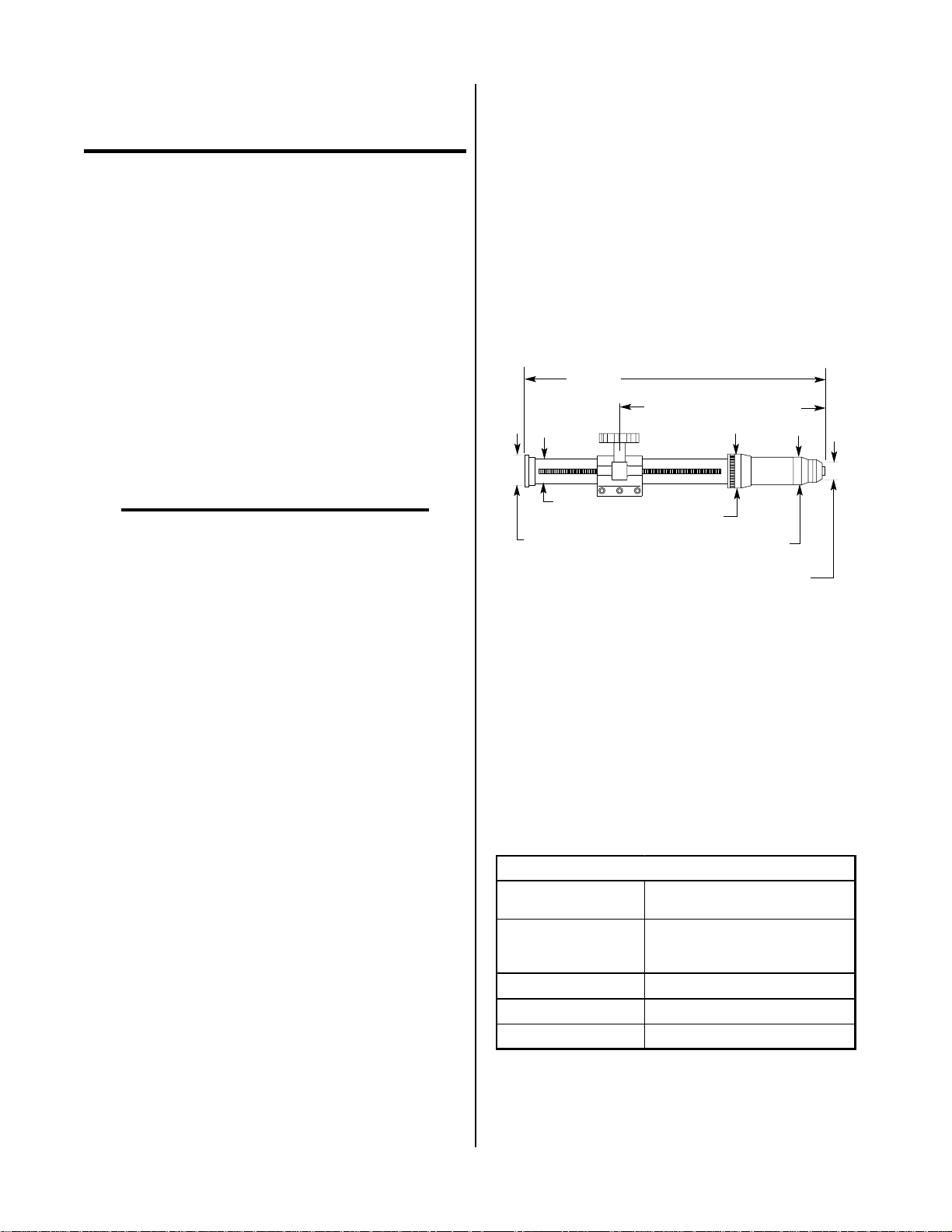
1. Maximizer 300 Torch Configuration & Dimensions
Maximizer 300 Machine Torch is supplied with a
Metal Rack and Pinion Mounting Assembly. An optional Phenolic Pinch Block Mounting Assembly is
available.
17.350 in
(441 mm)
1.38 in
(35 mm)
1.875 in
(47.6 mm)
A-01023
Min. 6.750 in (171.5 mm)
Max. 11.125 in (282.6 mm)
1.937 in
(49.2 mm)
1.531 in
(38.9 mm)
0.718 in
(18.2 mm)
Figure 2-1 Maximizer 300 Machine Torch
2. Torch Leads Length
25 ft (7.6 m)
50 ft (15.2 m)
Extendable up to 100 ft (30.5 m) from the Power Sup-
ply
3. Torch Ratings
Torch Ratings
Ambien t
Temperature
104° F
(40° C)
Duty Cycle
Maximum Current
Vol ta g e (V
Arc Strikin g Voltage
peak
100% @ 150 Amps @ 0.5 gpm
(1.89 lpm) Coolant Flow Rate
300 Amps
)
500V
12 kV
Manual 0-2554 2-1 INTRODUCTION
Page 16

4. Cutting Range
10. Secondary Water Requirements
Most materials up to 2 inch (50.8 mm)
Up to 3/4 inch (19 mm) for production speed cutting
5. Pierce Rating
3/4 inch (19 mm)
6. Transfer Distance
3/8 inch (10 mm)
7. Torch Parts
Gas Distributor , Electrode, T ip, Shield Cup Body , End
Cap
8. Plasma Gas Requirements
a. Plasma Gas: Compressed Air, Oxygen (O2), Ni-
trogen (N2), or Ar gon/Hydrogen (Ar/H2)
b. Pressure: 65 to 75 psi (4.5 to 5.2 bar)
CAUTION
Maximum input gas pressure must not exceed 125
psi (8.6 bar)
c. Hot Flow
Cutting: 22 - 28 scfh (10.4 - 13.2 lpm)
Gouging: 22 - 43 scfh (10.4 - 20.3 lpm)
scfh = standard cubic feet/hour
NOTE
Hot flow is measured with the main arc activated.
When pressure is set correctly the plasma gas flow
rate is significantly higher until the arc is initiated.
9. Secondary Gas Requirements
a. Secondary Gas: Compressed Air, Carbon Diox-
ide (CO2), or Nitrogen (N2)
b. Pressure: 65 to 75 psi (4.5 to 5.2 bar)
a. Water Source (See Notes): Clean drinking qual-
ity tap water can be used as a secondary
b. Water Pressure: Minimum 50 psi (3.5 bar)
c. Water Flow: Cutting: 6 gph (35.2 lph)
NOTES
Tap water should only be used as a secondary on
machine torches.
The tap water source does not need to be deionized,
but in water systems with extremely high mineral
content a water softener is recommended.
Tap water with high levels of particulate matter
must be filtered.
11. Weight (without leads)
1.0 lb (0.45 kg)
2.04 Options And Accessories
These items can be used to customize a standard system
for a particular application or to further enhance performance (refer to Section 6 for ordering information).
• Phenolic (plastic) Pinch Block Mounting Assembly
For machine mounted torch applications where a nonmetal mounting assembly is desired.
• Torch Leads Extension
The leads extension is part of the system to extend
the Torch from the Power Supply. Accessories are
available to extend the T orch fr om the Power Supply
up to 100 ft (30.5 m).
• Spare Parts Kits
Kits contain replacement front-end torch parts and
tools. Spare parts kits are available for air, oxygen
(O2), nitrogen (N2), and argon-hydrogen (Ar/H2)
cutting.
CAUTION
Maximum input gas pressure must not exceed 125
psi (8.6 bar)
c. Flow - Cutting or Gouging: 220 scfh (103 lpm)
scfh = standard cubic feet/hour
INTRODUCTION 2-2 Manual 0-2554
Page 17
2.05 Introduction to Plasma
B. Gas Distribution
A. Plasma Gas Flow
Plasma is a gas which has been heated to an extremely
high temperature and ionized so that it becomes electrically conductive. The plasma arc cutting and gouging
process uses this plasma to transfer an electrical arc to
the workpiece. The metal to be cut or removed is melted
by the heat of the arc and then blown away.
While the goal of plasma arc cutting is separation of the
material, plasma arc gouging is used to remove metals to
a controlled depth and width.
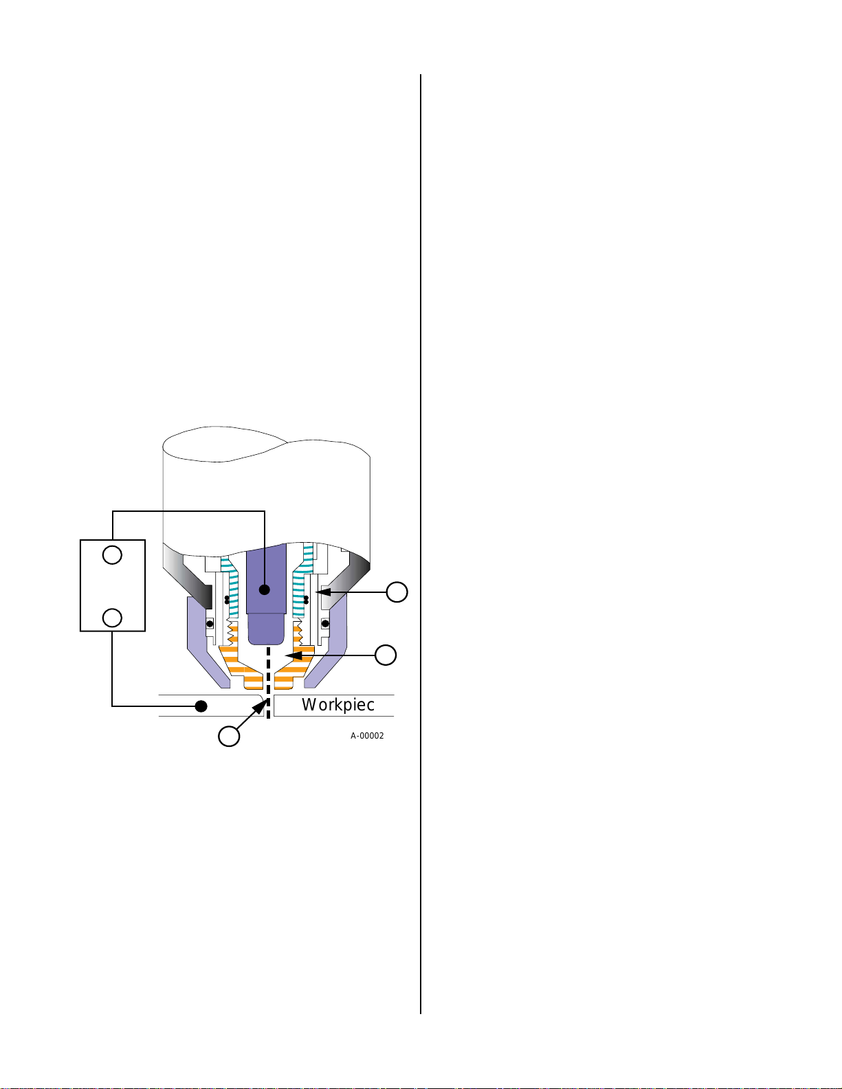
In a Plasma Cutting T o rch a cool gas such as air or nitr ogen (N2) enters Zone B (refer to Figure 2-2), where a pilot
arc between the electrode and the torch tip heats and ionizes the gas. The main cutting arc then transfers to the
workpiece through the column of plasma gas in Zone C.
_
Power
Supply
A
+
B
The plasma gas flows into the torch through the positive
lead, through the gas distributor, around the electrode,
and out through the tip orifice.
The secondary gas flows into the torch through the secondary gas hose, down around the outside of the torch
gas distributor, and out between the tip and shield cup
around the plasma arc.
C. Pilot Arc
When the torch is started a pilot arc is established between the electrode and cutting tip. This pilot arc creates
a path for the main arc to transfer to the work.
D. High Frequency
Because direct current (DC) alone is not sufficient to strike
the pilot arc, high frequency is also used. The high frequency jumps between the tip and electrode with the DC
following, then the high frequency turns off.
E. Main Cutting Arc
DC power is also used for the main cutting arc. The negative output is connected to the torch electrode through
the torch lead. The positive output is connected to the
workpiece via the work cable and to the torch through a
pilot wire in the positive lead.
F. Interlocks
T wo pressur e switches act as an interlock for the gas supply . If supply pressur e falls below minimum requirements
the pressure switches will open, shutting off the power
to the contactors, and the GAS indicator , if supplied, will
go out. When adequate gas supply pressure is available
the pressure switches close, allowing power to be r esumed
for cutting.
A flow switch acts as an interlock for the closed loop coolant supply. If the flow switch does not activate then the
Power Supply will not power ON. The flow switch will
not activate if there is low coolant level, or torch front
end parts (tip or electrode) are not installed.
C
Workpiece
A-00002
Figure 2-2 Typical Torch Head Detail
By forcing the plasma gas and electric arc thr ough a small
orifice, the torch delivers a high concentration of heat to
a small area. The stiff, constricted plasma arc is shown in
Zone C (Figure 2-2). Direct current (DC) straight polarity is used for plasma cutting, as shown in the illustration.
Zone A (Figur e 2-2) is used as a secondary gas that cools
the torch. This gas assists the high velocity plasma gas in
blowing the molten metal out of the cut allowing for a
fast, slag-free cut. Compressed air, supplied by either a
cylinder , plant air system or CO2 is normally used as the
secondary gas.
Manual 0-2554 2-3 INTRODUCTION
Page 18

INTRODUCTION 2-4 Manual 0-2554
Page 19
SECTION 3:
INSTALLATION
3.01 Introduction
This Section describes installation of the Liquid Cooled
Maximizer 300 Torch. These instructions apply to the
T orch and Leads Assemblies only; installation procedures
for the Power Supply , Options, and Accessories are given
in Manuals specifically provided for those units.
The complete installation consists of:
1. Site Selection
2. Unpacking
3. Setting Up Torch
4. Connecting Torch
5. Gas Connections
6. Operator Training
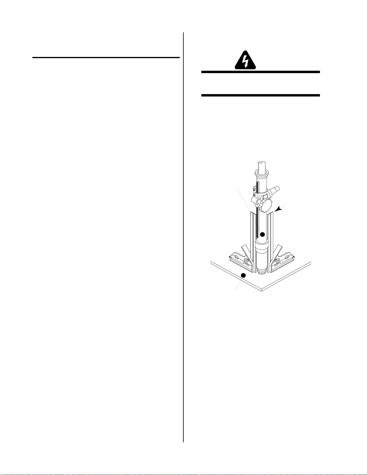
3.04 Setting Up Machine Torch
WARNING
Disconnect primary power at the source before disassembling the torch or torch leads.
Metal mounting tubes with rack and pinion assemblies
are standard for machine tor ches.
1. Mount the torch assembly on the cutting table.
2. To obtain a clean vertical cut, use a square to align the
torch perpendicular to the surface of the workpiece.
Rack and
Pinion Mounting
Assembly
3.02 Site Location
Select a clean, dry location with good ventilation and adequate working space around all components.
Review the safety precautions in the front of this manual
to be sure that the location meets all safety requirements.
3.03 Unpacking
The product is packaged and protected to prevent damage during shipping.
1. Unpack each item and remove all packing material.
2. Locate the packing list(s) and use the list to identify and account for each item.
3. Inspect each item for possible shipping damage.
If damage is evident, contact your distributor
and/or shipping company before proceeding with
system installation.
Square
A-00660
Workpiece
Figure 3-1 Machine Torch Set-Up
Manual 0-2554 3-1 INST ALLATION
Page 20
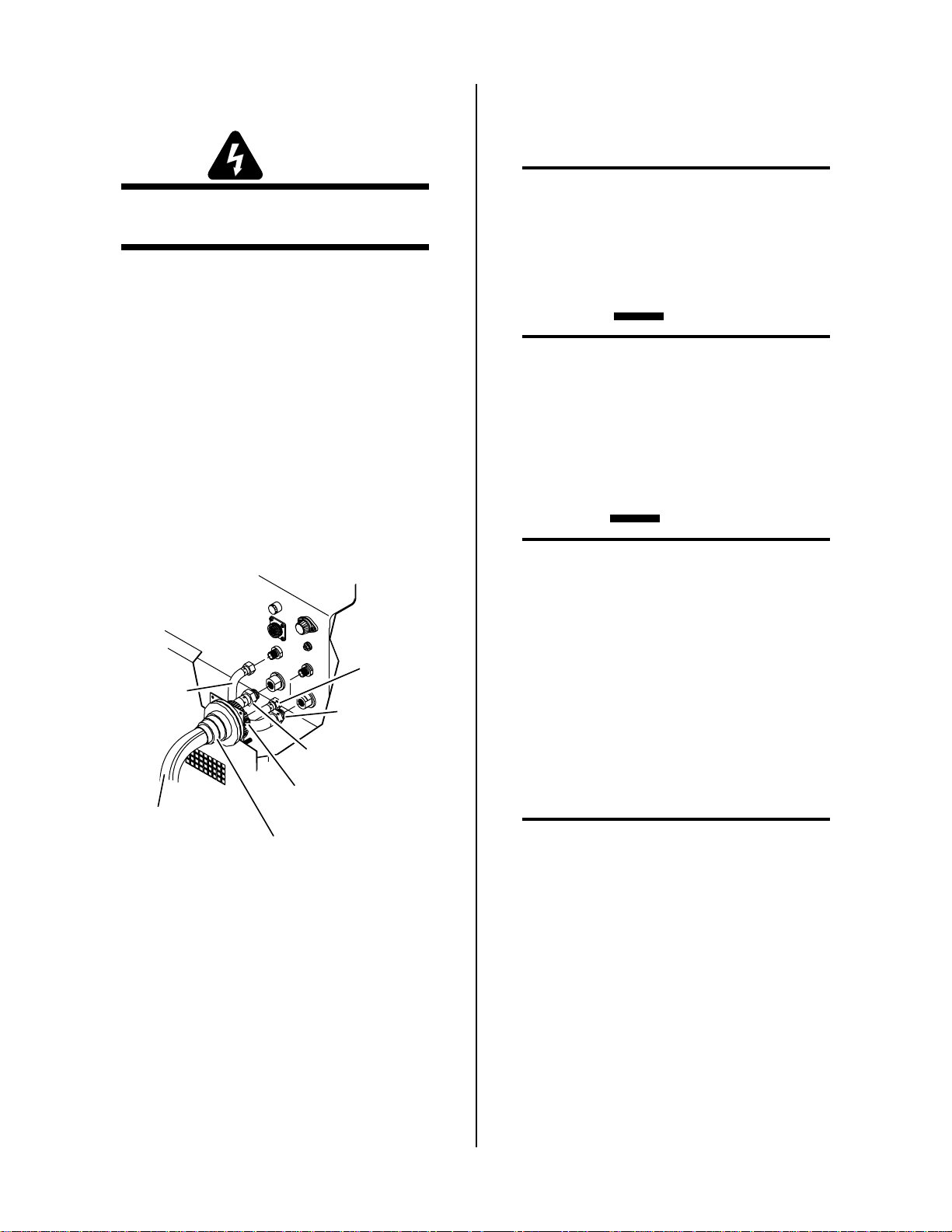
3.05 Connecting T orc h
7. Place the hose clamp over the shield and hub. T ighten
the hose clamp to secure the shielding braid to the
hub.
WARNING
Disconnect primary power at the source before disassembling the torch or torch leads.
The Torch Leads connect directly to a bulkhead inside
the Power Supply. Connect the Torch Leads per the following procedure:
1. Remove the tape securing the shield of the torch leads
to the leads.
2. Unfold the shield towards the end of the leads.
3. Feed the torch leads through the boot on the front
panel of the Power Supply.
4. Feed the torch leads through the supplied Hose
Clamp.
5. Connect the torch leads connectors to the bulkhead
connections.
Plasma
Gas Lead
Secondary
Gas Lead
Torch Leads
Extension
Assembly
Hose Clamp
Torch Leads
Extension Boot
Coolant Return
Lead
Coolant Supply
Lead
A-01008
NOTE
Make sure that the shielding braid is pulled back
as far as possible from the bulkhead connections.
Leave any extra shielding braid between the hose
clamp and the front panel area.
8. Check the torch for proper parts assembly .
CAUTION
The torch parts (gas distributor , electr ode, tip, and
shield cup) must correspond with plasma and secondary selection, output current level, and type of
operation (cutting or gouging). Refer to Section
4.04, Torch Parts Selection.
3.06 Gas Selection
CAUTIONS
Maximum input gas pressure must not exceed 125
psi (8.6 bar)
Air supply must be free of oil, moisture, and other
contaminants. Excessive oil and moisture may
cause double-arcing, rapid tip wear, or even complete torch failure. Contaminants may cause poor
cutting performance and rapid electrode wear.
The type of operation will determine the best gases to be
used. Refer to the following and select the plasma and
secondary gases that best fit the operation(s):
A. Plasma Gases
NOTE
Refer to Appendix 2, Cutting Speed Charts, for
proper gas pressure and flow rates.
1. Air Plasma
Figure 3-2 Torch Leads Connection to Power
Supply
6. Pull the shielding braid towards the front panel as far
as it will go up and over the brass hub. The hub is
part of the Boot Assembly and provides the grounding point for the shielding in the torch leads.
• Most often used on ferrous or carbon base materials to obtain good quality at faster cutting speeds.
• Air plasma is normally used with air secondary.
• Only clean, dry air is recommended for use as
plasma gas. Any oil or moisture in the air supply
will substantially reduce torch parts life.
• Provides satisfactory results on nonferrous materials.
INST ALLATION 3-2 Manual 0-2554
Page 21

2. Nitrogen (N2) Plasma
• Provides better cut quality on nonferrous materials
such as stainless steel and aluminum.
• Can be used in place of air plasma with air secondary or carbon dioxide (CO2).
• Provides much better parts life than air.
• A good clean welding grade nitrogen should be
used.
3. Argon/Hydrogen (Ar/H2) Plasma
2. Carbon Dioxide (CO
•CO
secondary is used with nitrogen or Ar/H2
2
) Secondary
2
plasma.
• Provides good cooling and maximizes torch parts
life.
• Provides good cut quality on ferrous or nonferrous
material.
• May reduce smoke when used with Ar/H2 plasma.
NOTE
• Recommended for use on 3/4 in (19 mm) and thicker
stainless steel. Recommended for 1/2 inch (12 mm)
and thicker nonferrous materials. Ar/H2 is not nor mally used for thinner nonferrous materials because
less expensive gases can achieve similar cut quality.
• Poor cut quality on ferrous materials (carbon steel).
• Provides faster cutting speeds and high cut quality
on thicker materials to offset the higher cost.
• A 65% argon/35% hydrogen mixture should be
used.
4. Oxygen (O
) Plasma
2
• Oxygen is recommended for cutting ferrous materials (carbon steel).
• Provides faster cutting speeds.
• Provides very smooth finishes and minimizes nitride build-up on cut surface (nitride build-up can
cause difficulties in producing high quality welds
if not removed).
B. Secondary Gases
NOTE
Refer to Appendix 2, Cutting Speed Charts, for
proper gas pressure and flow rates.
When CO2 is used as the secondary gas, twenty
(50 lb) cylinders must be manifolded together or a
bulk CO2 system used to get the required flow rate
of 220 scfh. Shop compressed air is a good alternative if providing the required CO2 flow rate is not
feasible.
3. Nitrogen (N2) Secondary
• Nitrogen secondary is used with Ar/H2 plasma.
• Provides smooth finishes on nonferrous materials.
• May be used with nitrogen plasma in order to operate from one compressed gas cylinder - but torch
parts life may be shorter than with CO2 secondary.
• May reduce smoke when used with Ar/H2 plasma.
4. Water Secondary
• W ater secondary should be used only in mechanized
applications - never in hand cutting!
• Normally used with nitrogen, Ar/H2, or air plasma.
• Provides very smooth cut surface.
• Reduces smoke and heat input to the workpiece.
• Effective up to 1 inch maximum material thickness.
• Tap water provides low operating expense.
1. Compressed Air Secondary
• Air secondary is normally used when operating
with air plasma and occasionally with nitrogen
plasma.
• Improves cut quality on some ferrous materials.
• Inexpensive - reduces operating costs.
Manual 0-2554 3-3 INST ALLATION
Page 22

3.07 Gas Connection
A. Connection
Connect the gases to the Power Supply as described in
the Power Supply Operating Manual (0-2251) supplied
with the Power Supply.
CAUTION
Air supply must be free of oil, moisture, and other
contaminants. Excessive oil and moisture may
cause double-arcing, rapid tip wear, or even complete torch failure. Contaminants may cause poor
cutting performance and rapid electrode wear.
B. Checking Air Quality
To test the quality of air, place a welding filter lens in
front of the torch and turn on the gas. Any oil or moisture in the air will be visible on the lens. Do not initiate
an arc!
C. Filtering
An in-line pneumatic dryer/evaporator type air filter,
capable of filtering to at least 5 microns, is required when
using air from a compressor. This type filter will insure
that moisture, oil, dirt, chips, rust particles, and other
contaminants from the supply hose do not enter the torch.
For highly automated applications, a refrigerated drier
may be used.
NOTE
Do not use an air line filter with high pressure gas
cylinders.
INST ALLATION 3-4 Manual 0-2554
Page 23

SECTION 4:
OPERATION
4.01 Introduction
This Section provides a description of the Liquid Cooled
Model Maximizer 300 T orch Assembly followed by operating procedures.
4.02 Functional Overview
The Liquid Cooled Model Maximizer 300 Torch is designed to operate with the Merlin 15XC Power Supply to
provide a plasma cutting system which can cut most metals from gauge thickness up to 2 inches. With a quick
change of torch parts the torch can be used for plasma
arc gouging.
4.03 Getting Started
D. Gas Supplies
Select desired gas supplies. Make sure gas sources
meet requirements (refer to Section 2.03, Specifications & Design Features). Check connections and turn
gas supplies on.
E. Purge System
On the Power Supply place the ON/OFF switch to
the ON position. An automatic gas purge (pr e-flow)
will remove any condensation that may have accumulated in the torch and leads while the system was
shut down. The torch cannot be activated during the
purge cycle (pre-flow). After the purge is complete,
if the RUN/SET/PURGE switch is in SET or PURGE
position, gas will flow. If the switch is the in RUN
position there will be no gas flow.
F. Current Output Level
At the Power Supply set the desired current output
level to a maximum of 150 amperes.
This procedure should be followed at the beginning of
each shift:
WARNING
Disconnect primary power at the source before assembling or disassembling stacked modules, individual modules, torch parts, or torch and leads assemblies.
A. T or ch Parts
Check the torch for proper assembly. Install proper
torch parts for the desired application (refer to Section 4.04, Torch Parts Selection).
B. Input Power
1. Check the power source for proper input voltage.
2. Make sure that the Power Supply in the system is
set for the proper voltage (refer to appropriate
Power Supply Operating Manual for connections
or adjustments).
G. Pressure Settings
NOTE
Refer to Appendix 2, Cutting Speed Charts, for
recommended gas pressure for the material being
cut.
Place the RUN/SET/PURGE switch to the SET position. Adjust PLASMA and SECONDAR Y GAS pressure control to 65 psi (4.5 bar).
H. Ready for Operation
Return the RUN/SET/PURGE switch to RUN position.
The system is now ready for operation.
NOTE
Refer to Appendix 1 for a detailed block diagram of
the Sequence Of Operation.
3. Close main disconnect switch or plug unit in to
supply primary power to the system.
C. Work Cable
Check for a solid work cable connection to the workpiece.
Manual 0-2554 4-1 OPERATION
Page 24

4.04 Torch Parts Selection
Depending on the type of operation to be done determines
the torch parts to be used.
Torch parts:
Shield Cup Body, End Cap, Tip, Electrode, Gas Distributor
Type of operation:
Standoff cutting or gouging
Refer to Section 6.04, T orch Consumables, for the various
torch parts.
CAUTION
Do not interchange parts. Make sure both the tip
and electrode in the torch correspond with the
plasma and secondary in use and the type of operation (cutting or gouging).
T o change the torch parts for a differ ent operation use the
following procedure (See Note):
NOTE
A multi-purpose wrench is supplied for changing
the tip, electrode and gas distributor in the torch
head.
Torch Head
Electrode
Gas Distributor
Shield Cup Body
Art # A-02207
Tip
End Cap
Figure 4-2 Liquid Cooled Torch Parts
2. Using the multi-purpose wrench (5/8 inch slot)
remove the tip.
3. Tilt the torch head to remove the gas distributor.
The end of the multi-purpose wrench can be used
to help remove the gas distributor.
4. Using the multi-purpose wrench (electrode area)
remove the electrode.
5. Install the desired electr ode for the operation into
the torch head. The circular area around the
wrench used for electrodes will also align the electrode in the torch head. This will prevent installing electrodes on an angle and cross threading the
electrode in the torch head.
Multi-Purpose Wrench
(Catalog Number 20-0001)
Gas Distributor Notch
Used with 11/16" (17.5 mm)Tip
Used for 11/16" ( 17.5 mm)
Across Tip Flats
This Side
T o wards Torch
Used for Electrodes
Used for 5/8" (15.9 mm)
Gas Distributor Notch
Used with 5/8" (15.9 mm)Tip
Across Tip Flats
A-01639
Figure 4-1 Multi-Purpose Wrench
1. Unscrew and remove the shield cup body and end
cap from the torch head.
6. Install the desired gas distributor and tip for the
operation into the torch head.
NOTE
Be careful not to overtighten the electrode and tip
when reinstalling.
7. Hand tighten the shield cup body and end cap
until it is seated on the torch head. If resistance is
felt when installing the cup, check the threads before proceeding.
OPERATION 4-2 Manual 0-2554
Page 25

4.05 Cut Quality
E. Bottom Dross Build-up
NOTE
Cut quality depends heavily on set-up and parameters such as torch standoff, alignment with the
workpiece, cutting speed, gas pressures, and operator ability.
Cut quality requirements differ depending on the application. For instance, nitride build-up and bevel angle may
be major factors when the surface will be welded after
cutting. Dross-free cutting is important when finish cut
quality is desired to avoid a secondary cleaning operation. The following cut quality characteristics are illustrated in the following figure:
Kerf Width
Cut Surface
Bevel Angle
Top
Spatter
Top Edge
Rounding
Molten material which is not blown out of the cut
area and re-solidifies on the plate. Excessive dross
may require secondary clean-up operations after cutting.
F . K erf Width
The width of the cut (or the width of material removed during the cut).
G. Top Spatter (Dross)
Top Spatter or dross on the top of the cut caused by
slow travel speed, excess cutting height, or cutting
tip whose orifice has become elongated.
H. Various Materials and Thicknesses
The following table defines the cut quality on various materials and thicknesses:
Dross
Build-Up
Cut Surface
Drag Lines
Figure 4-3 Cut Quality Characteristics
A. Cut Surface
The desired or specified condition (smooth or rough)
of the face of the cut.
B. Nitride Build-Up
Nitride deposits can be left on the surface of the cut
when nitrogen is present in the plasma gas stream.
These buildups may create difficulties if the material
is to be welded after the cutting process.
C. Bevel Angle
The angle between the surface of the cut edge and a
plane perpendicular to the surface of the plate. A perfectly perpendicular cut would result in a 0° bevel
angle.
D. Top-Edge Rounding
A-00007
Rounding on the top edge of a cut due to wearing
from the initial contact of the plasma arc on the workpiece.
Manual 0-2554 4-3 OPERATION
Page 26

Typical Cut Quality on Various Materials
Type of Material
Type of Gas es Material Thickne ss Carbon Steel Stainless Alumin um
Air Plasma a n d
Air Se c o n d a r y
Nitrogen Plasma and
Water Secondary
Ar/H 2 Pla sma an d
N2 or CO2 Secondary
Oxygen Plasma and
Air Seconda ry
Gauge to 2 inches
(Gauge to 50.8 mm)
Gauge to 1/4 inch
(Gauge to 6.4 mm)
1/4 to 1 inch
(6.4 to 2 5. 4 mm)
1/4 to 1/2 inch
(6.4 to 1 2. 7 mm)
1/2 to 2 inches
(12.7 to 50.8 mm)
Gauge to 3/8 inch
(Gauge to 9.5 mm)
3/8 to 2 inches
(9.5 to 5 0. 8 mm)
Description of Cut Characteristics:
Excellent - Minimum bevel (0 - 4°), minimum kerf (2 x
tip orifice diameter), little or no dross, smooth
cut surface.
Good Good Good
NR Good Good
NR Excellen t Goo d - Excellen t
NR NR Excellent
NR Excellent Excellent
Good NR NR
Excellent NR NR
4.06 Operating the System
WARNINGS
Good - Slight bevel (0 - 10°), slightly wider kerf (2-1/2 x
tip orifice diameter), some dross (easily removed),
medium-smooth cut surface, slight top edge
rounding.
Fair - Excessive bevel (over 10°), wide kerf (over 2-1/2 x
tip orifice diameter), medium to heavy dross, rough
cut surface, top edge rounding.
NR - Not Recommended.
NOTE
Cut quality depends heavily on set-up and parameters such as torch standoff, alignment with the
workpiece, cutting speed, gas pressures, and operator ability.
Disconnect primary power at the source before disassembling the power supply, torch, or tor ch leads.
Frequently review the Important Safety Precautions in Section 1 of this manual. Be sure the operator is equipped with proper gloves, clothing, eye
and ear protection. Make sure no part of the
operator’s body comes into contact with the workpiece while the torch is activated.
Sparks from the cutting process can cause damage
to coated, painted, and other surfaces such as glass,
plastic and metal.
Handle torch leads with care and protect them fr om
damage.
A. Piloting
Piloting is harder on parts life than actual cutting because the pilot arc is directed from the electrode to
the tip rather than to a workpiece. Whenever possible, avoid excessive pilot arc time to improve parts
life.
OPERATION 4-4 Manual 0-2554
Page 27

B. Torch Standoff
Improper standoff (the distance between the torch
tip and workpiece) can adversely affect tip life as well
as shield cup life. Standoff may also significantly
affect the bevel angle. Reducing standoff will generally result in a reduced bevel angle.
C. Edge Star ting
NOTE
Edge starting is not recommended for machine type
operations as most of the operations use the standoff method of starting and finishing on the workpiece. Starting or finishing off the workpiece will
reduce parts life.
If edge starts are required, hold the torch perpendicular to the workpiece with the front of the tip near
(not touching) the edge of the workpiece at the point
where the cut is to start. When starting at the edge
of the plate, do not pause at the edge and force the
arc to "reach" for the edge of the metal. This effect
will cause reduced tip life. Establish the cutting arc
as quickly as possible.
D. Direction of Cut
ten be wiped off with a welding glove. "Slow speed
dross" is normally present on the bottom edge of the
plate. It can vary from a light to heavy bead, but
does not adhere tightly to the cut edge, and can be
easily scraped off. "High speed dross" usually forms
a narrow bead along the bottom of the cut edge and
is very difficult to remove. When cutting a troublesome steel, it is sometimes useful to reduce the cutting speed to produce "slow speed dross". Any resultant cleanup can be accomplished by scraping, not
grinding.
4.07 Machine T orch Operation
A. Cutting With Machine T orch
The machine torch can be activated by remote control pendant or by a remote interface device such as CNC.
1. Use a square to check that the torch is perpendicular to the workpiece to obtain a clean, vertical cut.
Rack and
Pinion Mounting
Assembly
In the Liquid Cooled Torch, the plasma gas stream
swirls as it leaves the torch to maintain a smooth column of gas. This swirl effect results in one side of a
cut being more square than the other . Viewed along
the direction of travel, the right side of the cut is more
square than the left. To make a square-edged cut
along an inside diameter of a circle, the torch should
move counterclockwise around the circle. To keep
the square edge along an outside diameter cut, the
torch should travel in a clockwise direction.
Left Side
Cut Angle
Right Side
Cut Angle
Figure 4-4 Side Characteristics Of Cut
E. Dross
When dross is present on carbon steel, it is commonly
referred to as either “high speed, slow speed, or top
dross”. Dross present on top of the plate is normally
caused by too great a torch to plate distance. "Top
dross" is normally very easy to remove and can of-
A-00512
Square
A-00660
Workpiece
Figure 4-5 Checking Alignment
2. To start a cut at the plate edge, position the center
of the torch along the edge of the plate (refer to
Figure 4-6)
3. The machine torch can be activated by the r emote
operator control panel, remote control pendant,
or by remote interface device such as CNC. After
a two second gas purge, the pilot arc will start.
The pilot arc will stay on as long as the torch is
activated.
Manual 0-2554 4-5 OPERATION
Page 28

4. With the pilot arc on, the main cutting arc will be
established when the torch is brought within 1/8
- 3/8 in (3 - 10 mm) of the workpiece. If the cutting arc is interrupted and the torch is still activated, as when cutting expanded metal, the pilot
arc will automatically restart. Deactivating the
torch will shut off either the pilot or main arc, depending on the mode of operation.
NOTE
Shown with
Rack and Pinion
Mounting Assembly
Refer to Auto-Restart Options in the Power Supply Operating Manual.
5. Cut with a standoff of 1/8 - 3/8 in (3 - 10 mm)
from the work. The torch should be held perpendicular to the workpiece while cutting. Start cutting slowly and adjust cutting speed for optimum
cutting performance. Refer to Section 4.08, Recommended Cutting Speeds, for typical cutting
speeds for various materials and material thicknesses.
B. Tra vel Speed
Proper travel speed is indicated by the trail of the arc
which is seen below the plate. The arc can be one of the
following:
1. Straight Arc
A straight ar c is perpendicular to the workpiece surface. This arc is generally recommended for the best
cut using air plasma on stainless or aluminum.
2. Leading Arc
The leading arc is directed in the same direction as
torch travel. A five degree leading arc is generally
recommended for air plasma on mild steel.
3. Trailing Arc
The trailing arc is directed in the opposite direction
as torch travel.
D
irection of Torch Travel
Standoff
Distance
Straight Arc
Trailing Arc
A-00662
Leading Arc
Figure 4-6 Machine Torch Operation
The arc characteristics vary with gases used, cutting
speed, material, and thickness. Air plasma normally
produces a straight arc (on stainless or aluminum),
while nitrogen plasma generally creates a 5° trailing
arc.
For optimum smooth surface quality , the travel speed
should be adjusted so that only the leading edge of
the arc column produces the cut. If the travel speed
is too slow, a rough cut will be produced as the arc
moves from side to side in search of metal for transfer.
Travel speed also affects the bevel angle of a cut.
When cutting in a circle or around a corner, slowing
down the travel speed will result in a squarer cut.
The power source output should be reduced also.
NOTE
Refer to the Power Supply Operating Manual for
any Corner Slowdown (CSD) adjustments that
may be required.
OPERATION 4-6 Manual 0-2554
Page 29

C. Piercing With Machine T orch
T o pier ce with a machine tor ch, the arc should be started
with the torch positioned as high as possible above the
plate while allowing the arc to transfer and pierce. This
standoff helps avoid having molten metal blow back onto
the front end of the torch.
When operating with a cutting machine, a pierce or dwell
time is required. Torch travel should not be enabled until the arc penetrates the bottom of the plate. As motion
begins, torch standoff should be reduced to the recommended 1/8 - 3/8 inch (3 - 9 mm) distance for optimum
speed and cut quality.
A standard shield cup is r ecommended for most machine
cutting applications. Do not allow an exposed torch tip
to contact the workpiece.
A method called “r unning start” is recommended when
piercing with a machine mounted torch. The torch should
be positioned far enough off the cutting line to allow the
pierce to be complete before the cutting line is reached.
This allowance depends on the thickness of the material
and the torch travel speed.
Piercing the plate is not recommended on plates having
a thickness greater than 3/4 in (19 mm). Blowback from
the piercing operation can shorten the life of torch parts.
All piercing should therefore be done as quickly as possible and at maximum amperage (150 amps) and maximum standoff.
4.08 Recommended Cutting Speeds
Cutting speed depends on material, thickness, and the
operator’s ability to accurately follow the desired cut line.
The following factors may have an impact on system performance:
• Torch parts wear
• Air quality
• Operator experience
• Torch standoff height
• Proper work cable connection
• Alloy content of material
NOTE
This information represents realistic expectations
using recommended practices and well-maintained
systems. Actual speeds may vary from those shown
in the charts depending on the alloy content of the
selected material.
For complete cutting speed chart data refer to Appendix
2.
4.09 Gouging
WARNINGS
Pierce off the cutting line and then continue the cut as
needed. Clean spatter and scale from the shield cup and
the tip as soon as possible. Spraying or dipping the shield
cup in anti-spatter compound will minimize the amount
of scale which adheres to it. This can significantly increase shield cup life.
Be sure the operator is equipped with proper gloves,
clothing, eye and ear protection and that all safety
precautions at the front of this manual have been
followed. Make sure no part of the operator’s body
comes in contact with the workpiece when the torch
is activated.
Disconnect primary power to the system before disassembling the torch, leads, or power supply.
Sparks from plasma gouging can cause damage to
coated, painted or other surfaces such as glass, plastic, and metal.
Check torch parts. The torch parts must correspond
with the type of operation. Refer to Section 4.04,
Torch Parts Selection.
A. Recommended Gases
Refer to the following table for characteristics of recommended gases when gouging with Maximizer 300
Torch:
Manual 0-2554 4-7 OPERATION
Page 30

Characteristi cs of Recommended Gases for Plasma Arc Gouging
Type of Gas Type of Material
Plasma Secondary Carbon Steel Stai nless Steel Al uminum
Air Air Excellent Good Fair
Nitrogen Air Good Good Fair
Nitrogen CO2 Good Good Good
Ar/H2 Nitrogen Good Excel l ent (Over 3/4 i n) Excellent
Ar/H2 Ar gon Good Ex cellent Exc ellent
B. Gouging Parameters
Gouging performance depends on parameters such
as torch travel speed, current level, lead angle (the
angle between the torch and workpiece), and the distance between the torch tip and workpiece (standoff).
C. Tor ch Tra vel Speed
Optimum torch travel speed for gouging is between
20 and 120 inches per minute (0.5 and 3.0 meters per
minute). Travel speed is dependent on current setting, lead angle, and mode of operation (hand or
machine torch).
D. Current Setting
Current settings depend on torch travel speed, mode
of operation (hand or machine torch), and the amount
of material to be removed.
E. Lead Angle
The angle between the torch and workpiece depends
on the output current setting and torch travel speed.
At 50 amps, the recommended lead angle is 35°. At a
lead angle greater than 45° the molten metal will not
be blown out of the gouge and may be blown back
onto the torch. If the lead angle is too small (less than
35°), less material may be removed, requiring more
passes. In some applications, such as removing welds
or working with light metal, this may be desirable.
Torch Head
35o
Standoff Height
1/4 - 3/8"
Workpiece
A-00743
Figure 4-7 Gouging Angle and Standoff Distance
F. Standoff Distance
The tip to work distance affects gouge quality and
depth. A standoff of 1/4 - 3/8 in (6.3 - 9.5 mm) allows
smooth, consistent metal removal. A smaller standoff may result in a severance cut rather than a gouge.
A standof f greater than 3/8 in (9.5 mm) may result in
minimal metal removal or loss of transferred main
arc.
G. Slag Build-up
Slag generated by gouging on materials such as carbon and stainless steels, nickels, and alloyed steels,
can be removed easily in most cases. Slag does not
obstruct the gouging process if it accumulates to the
side of the gouge path. However, slag build-up can
cause inconsistencies and irregular metal removal if
large amounts of material build up in front of the arc.
The build-up is most often a result of improper travel
speed, lead angle, or standoff height.
OPERATION 4-8 Manual 0-2554
Page 31

SECTION 5:
SERVICE
5.01 Introduction
This Section describes basic maintenance procedures performable by operating personnel. No other adjustments
or repairs are to be attempted by other than properly
trained personnel.
WARNINGS
Disconnect primary power at the source before disassembling the torch or torch leads.
Frequently review the Important Safety Precautions in Section 1 of this Manual. Be sure the operator is equipped with proper gloves, clothing, eye
and ear protection. Make sure no part of the
operator’s body comes into contact with the workpiece while the torch is activated.
Sparks from the cutting process can cause damage
to coated, painted, and other surfaces such as glass,
plastic and metal.
Handle torch leads with care and protect them fr om
damage.
5.02 General T orch Maintenance
A. Cleaning Torch
Even if precautions are taken to use only clean air
with a torch, eventually the inside of the torch becomes coated with residue. This buildup can affect
the pilot arc initiation and the overall cut quality of
the torch.
The inside of the torch should be cleaned with electrical contact cleaner using a cotton swab or soft wet
rag. In severe cases, the torch can be removed from
the leads (refer to Section 5.06, Servicing Machine
T orch Components) and cleaned more thor oughly by
pouring electrical contact cleaner into the torch and
blowing it through with compressed air.
CAUTION
Dry the torch thoroughly before r einstalling.
B. Checking Center Insulator
The center insulator separates the negative and positive sections of the torch. If the center insulator does
not provide adequate resistance, current which is intended for the pilot arc may be dissipated into the
torch head, resulting in torch failure.
WARNINGS
Disconnect primary power to the system before
disassembling the torch or torch leads.
DO NOT touch any internal torch parts while the
AC indicator light on the front panel of the power
supply is ON.
1. Remove the shield cup body, end cap, tip, gas distributor , and electrode from the tor ch. Disconnect
the torch leads from the system to isolate the torch
from power supply circuits.
2. Using an ohmmeter (set to 10K or higher), check
for continuity between the positive and negative
torch quick disconnect fittings. Infinite resistance
(no continuity) should be found. If continuity is
found, refer to Section 5.07, Torch and Leads
Troubleshooting.
C. Torch O-ring Lubrication
WARNINGS
Disconnect primary power to the system before
disassembling the torch or torch leads.
DO NOT touch any internal torch parts while the
AC indicator light on the front panel of the power
supply is ON.
Manual 0-2554 5-1 SERVICE
The internal o-rings on the torch head assembly (electrode, gas distributor and tip) require lubricating on
a scheduled basis. This will allow the o-rings to remain pliable and provide a proper seal. The o-rings
will dry out, becoming hard and cracked, if the oring lubricant is not used on a regular basis. This can
lead to potential leaks internally and externally . Failure of o-rings that seal against outside “air” entering
the torch assembly can cause severe contamination.
These contaminants can destroy or shorten the parts
life of tips, electrodes, and internal torch parts.
It is recommended to apply a very light film of oring lubricant, Catalog Number 8-4025, to the internal torch head assembly o-rings on a weekly basis.
Page 32
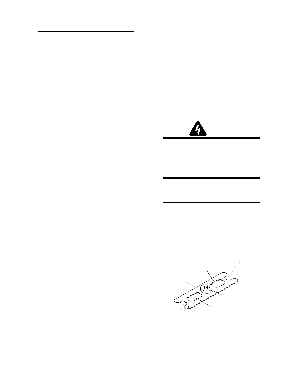
NOTE
g. Output current too high
DO NOT use other lubricants or grease, they may
not be designed to operate within high temperatures or may contain “unknown elements” that
may react with the atmosphere. This reaction can
leave contaminants inside the torch. Either of these
conditions can lead to inconsistent performance or
poor parts life.
5.03 Common Operating Faults
The following are the more common cutting faults and
the possible cause(s):
1. Insufficient Penetration
a. Cutting speed too fast
b. Torch tilted too much
c. Metal too thick
d. Worn torch parts
e. Cutting current too low
f. Non-Genuine Thermal Dynamics Parts
2. Main Arc Extinguishes
h. Torch tip contacting workpiece
i. Damaged or loose torch head components
j. Non-Genuine Thermal Dynamics Parts
5. Poor Pilot Starting
a. Non-Genuine Thermal Dynamics Parts
b. High coolant conductivity (refer to Power Supply
Manual)
5.04 Inspection and Replacement Consumable T orch Parts
WARNINGS
Disconnect primary power to the system before
disassembling the torch or torch leads.
DO NOT touch any internal torch parts while the
AC indicator light on the front panel of the Power
Supply is ON.
a. Cutting speed too slow
b. Torch standoff too high from workpiece
c. Cutting current too high
d. Work cable disconnected
e. Worn torch parts
f. Non-Genuine Thermal Dynamics Parts
3. Excessive Dross Formation
a. Cutting speed too slow
b. Torch standoff too high from workpiece
c. Worn torch parts
d. Improper cutting current
e. Non-Genuine Thermal Dynamics Parts
4. Short Torch Parts Life
a. Oil or moisture in air source
b. Exceeding system capability (material too thick)
c. Excessive pilot arc time
Remove the consumable torch parts per the following
procedure (See Note):
NOTE
A multi-purpose wrench is supplied for changing
the tip, electrode and gas distributor in the torch
head.
Multi-Purpose Wrench
(Catalog Number 20-0001)
Gas Distributor Notch
Used with 11/16" (17.5 mm)Tip
Used for 11/16" ( 17.5 mm)
Across Tip Flats
This Side
T o wards Torch
Used for Electrodes
Used for 5/8" (15.9 mm)
Gas Distributor Notch
Used with 5/8" (15.9 mm)Tip
Across Tip Flats
A-01639
d. Starting or finishing off the workpiece
Figure 5-1 Multi-Purpose Wrench
e. Plasma gas flow too low (incorrect pressure)
f. Improperly assembled torc h
SERVICE 5-2 Manual 0-2554
Page 33
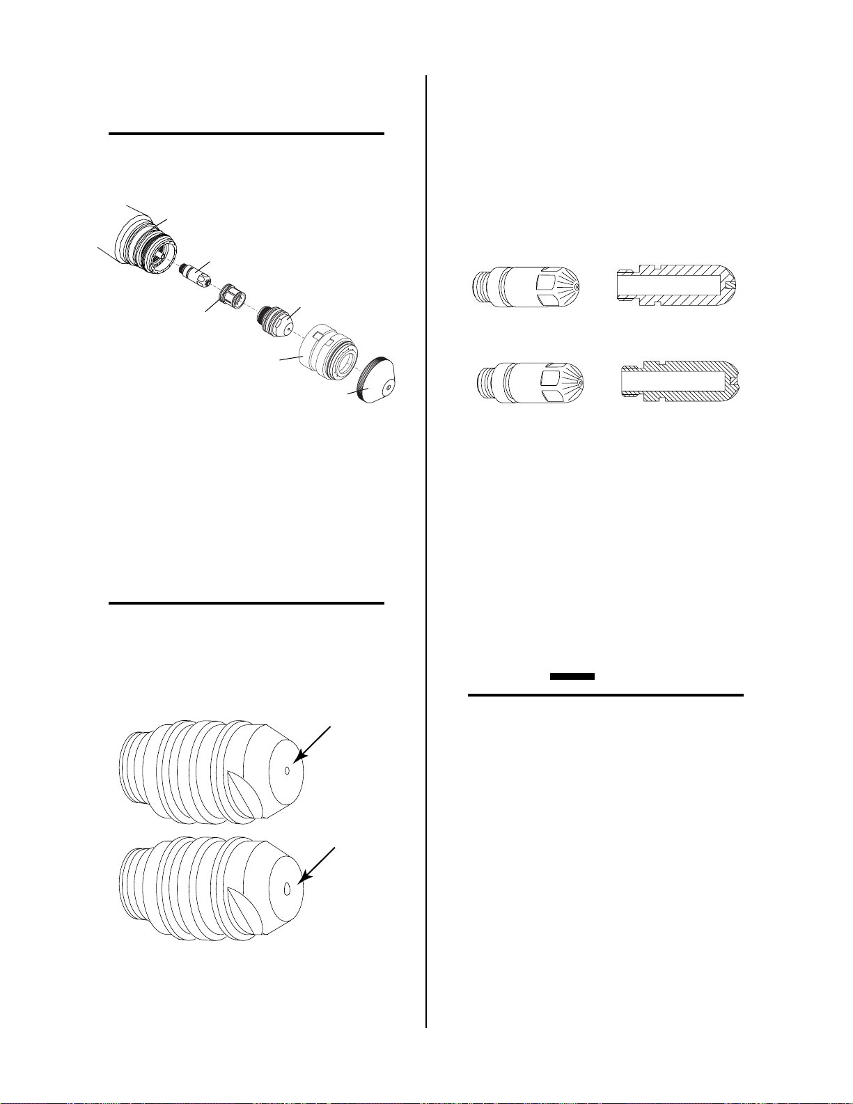
1. Unscrew and remove the shield cup body and end
cap from the torch head.
NOTE
Slag built up on the shield cup that cannot be removed may effect the performance of the system.
Torch Head
4. Tilt the torch head to remove the gas distributor. The
end of the multi-purpose wrench can be used to help
remove the gas distributor .. Check for excessive wear ,
plugged gas slots, or discoloration. Replace if necessary.
5. Using the multi-purpose wrench (electrode area) remove the electrode. Refer to Figure 5-4 and check the
face of the electrode for excessive wear.
Electrode
Gas Distributor
Shield Cup Body
Art # A-02207
Tip
End Cap
Figure 5-2 Consumable Parts
2. Inspect the cup for damage. Wipe it clean or replace
if damaged.
3. Using the multi-purpose wrench (5/8 inch slot) remove the tip. Check for excessive wear (indicated by
an elongated or oversized orifice). Replace the tip if
necessary.
NOTE
The tip, electrode and gas distributor have o-rings
on each part. The o-rings should be removed and a
light coating of o-ring lubricant (catalog number
8-4025) applied.
New Electrode
Worn Electrode
A-00256
Figure 5-4 Electrode Wear
6. Install the electrode and tighten with multi-purpose
wrench. Do not over tighten the electrode. The circular area around the wrench used for electr odes will
also align the electrode in the torch head. This will
prevent installing electrodes on an angle and cross
threading the electrode in the torch head.
7. Install the gas distributor.
8. Install the tip and tighten with the multi-purpose
wrench. Do not over tighten the tip.
CAUTION
Good Tip
Make sure both the tip and electrode correspond
with the plasma and secondary gases being used,
the current range, and the type of operation. Refer
to Section 4.04, Torch Parts Selection.
9. Hand tighten the shield cup body and end cap until it
is seated on the torch head. If resistance is felt when
installing the cup, check the threads before proceed-
Worn Tip
A-01578
ing.
Figure 5-3 Tip Wear
Manual 0-2554 5-3 SERVICE
Page 34

5.05 Troubleshooting Guide
A. Troubleshooting
This Sub-Section covers troubleshooting that requires
disassembly and electronic measurements. It is helpful
for solving many of the common problems that can arise
with this torch assembly.
B. No cutting output
1. Torch not properly connected to power supply
a. Check that torch leads are properly attached
to power supply and work cable is attached to
the workpiece
2. Faulty components in torch and leads assembly
B. How to use this Guide
The following information is a guide to help the Customer/Operator determine the most likely causes for
various symptoms.
This guide is set up in the following manner:
X. Symptom (Bold Type)
Any Special Instructions (Text Type)
1. Cause (Italic Type)
a. Check/Remedy (Text Type)
Locate your symptom, check the causes (easiest listed first)
then remedies. Repair as needed being sure to verify that
the unit is fully operational after any repairs.
A. Torch will not pilot when torch switch is activated
1. Power Supply RUN/SET/PURGE switch in SET position
a. Place RUN/SET/PURGE switch to RUN posi-
tion.
2. Torch switch activated during 20 second pre-flow
a. Release torch switch and wait at least 20 sec-
onds before activating switch again
3. Faulty torch parts
a. Inspect torch parts and replace if necessary. Re-
fer to Section 5.04, Inspection and Replacement
Consumable T o rch Parts
4. Gas pressure too high
a. Set pressure to 65 psi.
5. Faulty components in torch and leads assembly
a. Inspect torch assemblies and replace if neces-
sary. Refer to Section 5.07, Torch and Leads
Troubleshooting.
6. Faulty components in power supply system components
a. Return for repair or have qualified technician
repair per Service Manual.
a. Inspect torch assemblies and replace if neces-
sary. Refer to Section 5.07, Torch and Leads
Troubleshooting.
3. Faulty components in power supply system components
a. Return for repair or have qualified technician
repair per Service Manual.
C. Low cutting output with no control
1. Incorrect setting of AMPERAGE control on power supply
a. Check and adjust to proper setting.
2. Faulty components in torch and leads assembly
a. Inspect torch assemblies and replace if neces-
sary. Refer to Section 5.07, Torch and Leads
Troubleshooting.
3. Faulty components in power supply system components
a. Return for repair or have qualified technician
repair per Service Manual.
D. Limited output with no control
1. Poor input or output connections to power supply
a. Check all input and output connections.
2. Incorrect setting of AMPERAGE control on power supply
a. Check and adjust to proper setting.
3. Faulty components in torch and leads assembly
a. Inspect torch assemblies and replace if neces-
sary. Refer to Section 5.07, Torch and Leads
Troubleshooting.
4. Faulty components in power supply system components
a. Return for repair or have qualified technician
repair per Service Manual.
E. Erratic or improper cutting output
1. Poor input or output connections to power supply
a. Check all input and output connections.
2. Current set too low at power supply
a. Increase current setting.
SERVICE 5-4 Manual 0-2554
Page 35
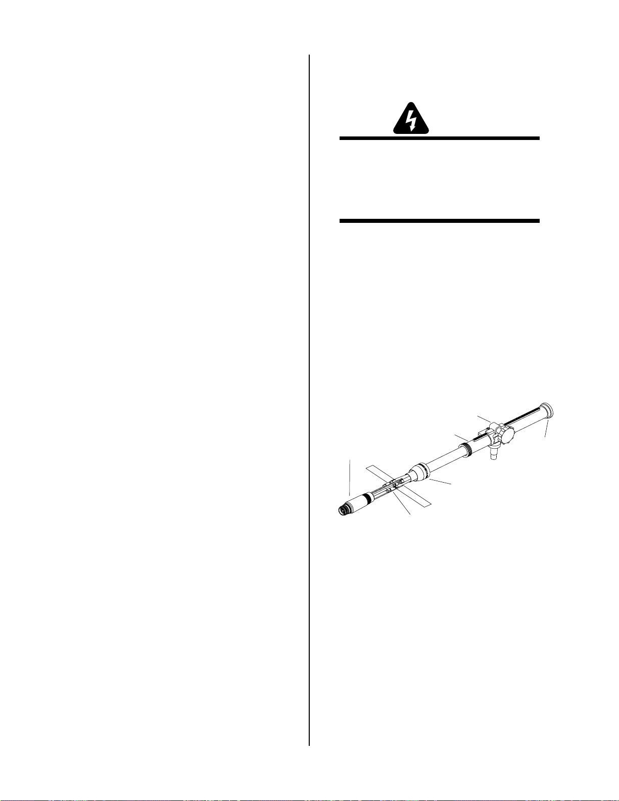
3. Torch is being moved too fast across workpiece
a. Reduce cutting speed (refer to Appendix 2, Cut-
ting Speed Charts).
5.06 Servicing Machine Torch Components
4. Excessive oil or moisture in torch
a. Hold torch 1/8 inch (3 mm) from clean surface
while purging and observe oil or moisture
buildup (do not activate torch)
F. No gas flow
1. Gas not connected or pressure too low
a. Check source for at least 70 psi (4.8 bar).
2. Faulty components in torch and leads assembly
a. Inspect torch assemblies and replace if neces-
sary. Refer to Section 5.07, Torch and Leads
Troubleshooting.
3. Faulty components in power supply system components
a. Return for repair or have qualified technician
repair per Service Manual.
G. Torch cuts but not adequately
1. Current set too low at power supply
a. Increase current setting
2. Improper plasma or secondary gas selected for application
WARNINGS
Disconnect primary power to the system before
disassembling the torch or torch leads.
DO NOT touch any internal torch parts while the
AC indicator light on the front panel of the Power
Supply is ON.
A. Removing Machine Tor c h Head
1. Remove the shield cup body, shield cup shield,
tip, gas distributor and electrode from the torch
head assembly .
2. Unscrew the positioning tube from the tor ch adaptor on the torch head assembly and slide the positioning tube back over the leads.
3. Unscrew the torch adaptor from the torch head
assembly. Slide the torch adaptor back over the
leads to expose the plasma (+), secondary, coolant supply (-), and coolant return connectors.
Pinion Assembly
a. Refer to Cut Quality, Section 4.05-H
3. Torch is being moved too fast across workpiece
a. Reduce cutting speed (refer to Appendix 2, Cut-
ting Speed Charts).
4. Excessive oil or moisture in torch
a. Hold torch 1/8 inch (3 mm) from clean surface
while purging and observe oil or moisture
buildup (do not activate torch)
5. Torch tip contacting workpiece
a. Increase standoff distance
6. Torch tip worn
a. Replace tip
7. Incorrect gas pressure
a. Set correct gas pressure
Machine
Torch Head
Positioning Tube
Lead Connections
Bushing
Torch Adaptor
A-00663
Figure 5-5 Torch Mounting Assembly
4. Disconnect the plasma (+), secondary , coolant supply (-), and coolant return connectors to allow removal of the torch head. Note the location of the
torch leads insulator which separates the negative and positive leads.
Manual 0-2554 5-5 SERVICE
Page 36

Coolant Return Lead
(LH Threads)
5.07 Torch & Leads Troubleshooting
A. General Information
Coolant
Supply (-) Lead
Secondary
Lead
Plasma (+) Lead
A-00664
Figure 5-6 Torch Head Removal
B. Reassembling Machine Torch Assembly
1. Connect the plasma (+), secondary, coolant supply (-), and coolant return connectors.
2. Slide the torch adapter down over the leads and
screw the adaptor securely onto the back of the
torch head assembly.
3. Slide the positioning tube down over the leads
and thread it into the torch adaptor on the torch
head assembly .
4. Install the front end torch parts.
Failures in the T orch and Leads can be isolated to the Torch
Head or T orch Lead components. To properly isolate the
failed part requires the use of an ohmmeter and a Hi-Pot
Tester.
WARNING
The use of a Hi-Pot T ester should be performed only
by a qualified electronic technician.
In the T orch Head the center insulator separates the negative and positive charged sections of the torch. If the center insulator does not provide adequate resistance, current which is intended for the pilot arc may be dissipated
into the torch head, resulting in torch failure.
In the Torch Leads the negative and positive leads are
isolated from each other. If there is not adequate resistance between the leads then torch failure may occur.
B. Quick Check Procedure
This quick check will identify major isolation failures in
the T orch Head or T or ch Lead components using an ohmmeter.
The actual assembly and consumables may vary for different torches but the basic procedure is the same for all
torches. Make the quick check on the Torch Head and
Leads per the following procedure:
WARNINGS
Disconnect primary power to the system before
disassembling the torch or torch leads.
DO NOT touch any internal torch parts while the
AC indicator light of the Power Supply is ON.
1. Remove the consumables from the torch.
2. Disconnect the torch leads from the power supply to isolate the torch from power supply circuits.
SERVICE 5-6 Manual 0-2554
Page 37

3. Using an ohmmeter (set to 10K or higher), check
for continuity between the positive and negative
torch fittings.
• If there is continuity between the two torch
fittings proceed to Step 4.
• If no continuity (infinite resistance) is found
between the two torch fittings proceed to paragraph C.
C. Checking Proper Isolation Resistance
Procedure
The Torch Head and Torch Leads should be tested further for insulation breakdown if no other fault has been
found. This procedure requir es the use of a Hi-Pot T ester .
WARNING
4. Remove the torch head from the leads (refer to
the proper Section on servicing the Torch Components).
5. With the torch head disconnected from the leads,
measure the resistance between negative fitting
or cathode body of the torch head and the positive fitting or anode body of the torch head.
No continuity (infinite resistance) should be measured between negative and positive sections of
the torch head.
• If there is continuity, torch head must be re-
placed.
• If no continuity (infinite resistance) is found
proceed to Step 6.
6. Check the torch leads by measuring the resistance
between the positive pilot lead connector and the
negative lead fitting.
• If there is continuity, torch leads must be re-
placed.
• If no continuity (infinite resistance) is found
proceed to paragraph ‘C’ (see NOTE).
NOTE
It is possible that the Torch Head and Torch Leads
will test properly with an ohmmeter. The Torch
Head and Torch Leads should be tested further for
insulation breakdown if no other fault can be found.
This procedure should be performed only by a qualified electronic technician.
1. To test the T orch Head center insulator for insulation breakdown use the following procedur e:
a. Remove the Torch Head Assembly from the
Torch Leads if not already done.
b. Remove the consumables from the T orch Head
Assembly if not already done.
c. Connect a Hi-Pot Tester capable of pr oducing
2500 V AC between the positive pilot lead and
the negative lead fittings.
d. Increase the output of the Hi-Pot Tester to a
maximum of 2500 VAC.
• If the voltage drops to 0 VAC or leakage
current is detected, then the Torch Head
center insulator is breaking down and the
Torch Head must be replaced.
• If the Torch Head center insulator passes
the test, then proceed to Step 2.
2. To test the Torch Leads for insulation breakdown
use the following procedure:
a. Connect the Hi-Pot Tester between the posi-
tive pilot lead and the negative lead fittings.
The fitting on the other end of the T orch Leads
must be separated (isolated) from each other.
b. Increase the output of the Hi-Pot Tester to a
maximum of 2500 VAC.
• If the voltage drops to 0 VAC or leakage
current is detected, then the insulation between the Torch Leads is breaking down
and the Torch Leads must be replaced.
• If the Tor ch Leads passes the test, then proceed to Step 3.
Manual 0-2554 5-7 SERVICE
Page 38

3. Visually check that the pilot lead connection and
negative lead connections are properly connected
and in good condition (no shorts or arcing).
• If problems are evident, repair or replace as
required.
• If there are no visual problems, then proceed
to Step 4.
4. Check the pilot lead, negative lead and control
wires for opens from one end of the torch leads to
the other .
• If open, replace leads or open component
of the T or ch Leads Assembly.
• If not open, then proceed to Step 5.
5. Check the pilot and control wires for shorts to
other components in the T o r ch Leads.
• If shorted, then replace Torch Leads.
• If not shorted, then proceed to Step 6.
6. Carefully reassemble the components and r echeck
the completed assembly per paragraph ‘B’, Step
3 to confirm that the components have been properly assembled.
This completes the checks for the proper operation of the
Torch Head and Tor ch Leads.
SERVICE 5-8 Manual 0-2554
Page 39

SECTION 6:
PARTS LISTS
6.01 Introduction
A. Pa rts List Breakdown
The parts list provides a breakdown of all replaceable
components. T orch Assemblies are field serviceable, so a
complete breakdown of parts is provided. The parts lists
are arranged as follows:
Section 6.03 Replacement Machine Torch Parts
Section 6.04 Torch Consumables
Section 6.05 Complete Assembly Replacements
Section 6.06 Torch Options And Accessories
Section 6.07 Spare Parts Kits
NOTE
Parts listed without item numbers are not illustrated, but may be ordered by the catalog numbers
shown.
B. Returns
If a product must be returned for service, contact your
authorized distributor. Materials returned without
proper authorization will not be accepted.
6.02 Ordering Information
Order replacement parts by catalog number and complete
description of the part or assembly, as listed in the description column of the Parts List. Also include the model
and serial number of the torch. Address all inquiries to
your authorized distributor .
Manual 0-2554 6-1 P A RTS LISTS
Page 40

6.03 Replacement Machine Torch Parts
Item # Qty Description Catalog #
1 1 Assembly, T or ch Head, Maximizer 300 9-6410
2 1 Lead Assembly
25 ft (7.6m) Length 4-2904
50 ft (15.2 m) Length 4-2905
3 1 Tube, Positioning, 1-3/8, With Rack (includes Item #4) 7-3207
4 1 Positioning Tube End Cap (Molded) 8-4204
5 1 Adapter , Torch to 1-3/8 Positioning Tube 8-2158
1 T o r ch Holder Assembly (Includes items #6 - 14) 7-2827
6 1 Torch Holder Sleeve 7-2896
7 1 Pinion Gear-Short 8-6074
8 1 Handwheel (Torch Holder) 9-4514
9 1 Low Profile Torch Holder (1-3/8" Dia) w/o Hardware 9-4515
10 1 Calibrated T or ch Holder Bushing (Includes item #11) 9-4366
11 1 #10-24 x 3/8 Hex Socket Set Screw, Cup Point See Note
12 1 5/32 Dia x 5/8 Lg Slotted Spring Pin See Note
13 1 3/8-24 x 3/8 Soc Hd Set Screw, Cup Point See Note
14 2 1/4-20 x 5/8 Hex Socket Head Screw See Note
NOTE: Item can be purchased locally.
P AR TS LISTS 6-2 Manual 0-2554
Page 41
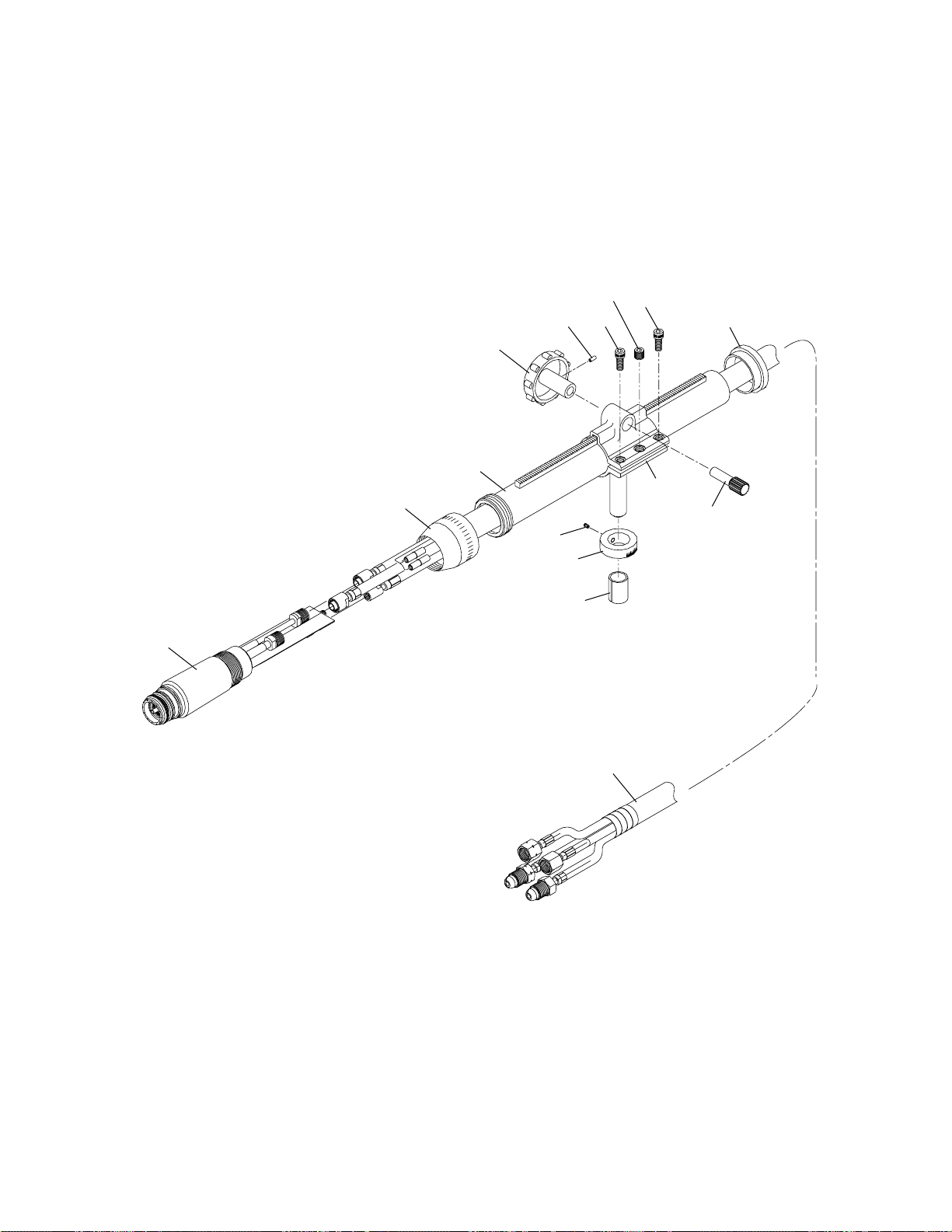
13
14
14
12
4
8
3
9
5
7
11
10
6
1
2
A-03220
Manual 0-2554 6-3 P A RTS LISTS
Page 42

6.04 Torch Consumables
Maximizer 300 With Merlin 15XC
Using Air (50 - 150 amps)
Electrode
50 - 225 amps
Catalog No. 20-1018
Art # A-03217
Gas
Distributor
50 - 225 amps
Catalog No. 20-0008
O-Ring
Cat. No. 8-3484
* - Licensed under U.S. Patent Nos. 5,120,930 and 5,132,512
Cutting Consumables
Tips
0.043" Orifice, 50 amps
Catalog No. 20-1030
0.055" Orifice, 100 amps
Catalog No. 20-1031
0.073" Orifice, 150 amps
Catalog No. 20-1032
for Underwater Cutting Catalog No. 20-1428
Shield Cup
Body
Standard Cutting
Catalog No. 20-1002
Ohmic Clip
Shield Cup Body
Catalog No. 20-1427
Underwater Cutting
Catalog No. 20-1029
Ohmic Clip Shield Cup Body
End Caps
Standard Cutting
50 amps
Catalog No. 20-1003
Standard Cutting
100 -225 amps
Catalog No. 20-1004
Underwater Cutting
100 - 300 amps
Catalog No. 20-1028 *
Using O2 (50 - 150 amps)
Electrodes
50 - 100 amps
Catalog No. 20-1015
150 amps
Catalog No. 20-1016
Art # A-03218
* - Licensed under U.S. Patent Nos. 5,120,930 and 5,132,512
Gas
Distributor
50 - 225 amps
Catalog No. 20-0008
O-Ring
Cat. No. 8-3484
Cutting Consumables
Tips
0.043" Orifice, 50 amps
Catalog No. 20-1030
0.055" Orifice, 100 amps
Catalog No. 20-1031
0.073" Orifice, 150 amps
Catalog No. 20-1032
for Underwater Cutting Catalog No. 20-1428
Shield Cup
Body
Standard Cutting
Catalog No. 20-1002
Ohmic Clip
Shield Cup Body
Catalog No. 20-1427
Underwater Cutting
Catalog No. 20-1029
Ohmic Clip Shield Cup Body
End Caps
Standard Cutting
50 amps
Catalog No. 20-1003
Standard Cutting
100 -225 amps
Catalog No. 20-1004
Underwater Cutting
100 - 300 amps
Catalog No. 20-1028 *
P AR TS LISTS 6-4 Manual 0-2554
Page 43

Maximizer 300 With Merlin 15XC
Using N2 or ArH2
Cutting Consumables
(100 - 150 amps)
Tips
Electrodes
50 - 300 amps - N2
Catalog No. 20-1023
100 - 300 amps - ArH2
Catalog No. 20-1025
Art # A-03219
Gas
Distributors
50 - 225 amps
Catalog No. 20-0008
300 amps
Catalog No. 20-1009
O-Ring
Cat. No. 8-3484
0.055" Orifice, 100 amps
Catalog No. 20-1031
0.073" Orifice, 150 amps
Catalog No. 20-1032
0.083" Orifice, 225 amps
Catalog No. 20-1033
NOTE:
If using a torch height control which offers an ohmic sensing feature, select a shield cup body with an ohmic clip tab.
Use catalog # 20-1427 for normal cutting and catalog 20-1428 for cutting underwater.
Shield Cup
Body
Standard Cutting
Catalog No. 20-1002
Ohmic Clip
Shield Cup Body
Catalog No. 20-1427
End Cap
Standard Cutting
100 -225 amps
Catalog No. 20-1004
Included with
Shield Cup Body
Torch Head
O-Ring Locations
Electrodes (All)
Small
Large
Gas Distributors (All)
Tips (All)
Small Large
Art # A-03019
Manual 0-2554 6-5 P A RTS LISTS
Page 44

6.05 Complete Assembly Replacements
Description Qty. Catalog #
Machine Torches with Leads and Rack & Pinion Mounting Assembly:
25 ft (7.6 m) Leads 1 2-6140
50 ft (15.2 m) Leads 1 2-6141
6.06 Torch Options And Accessories
Item # Qty Description Catalog #
1 1 Positioning Tube, Non Conductive, 1-3/8 O.D., Threaded End 7-3269
2 2 Body, Mounting, Pinch Block, 1-3/8 Pos. Tube 9-4513
3 1 Pin, Mounting, Pinch Block, Positioning Tube (0.625" Shaft Dia.) 9-4512
4 1 Torch Holder Sleeve (0.750" O. D.) 7-2896
5 3 #10-32 x 5/8 Phillips Pan Head Screw See Note
6 2 #10-32 x 1-1/4 Philips Pan Head Screw See Note
7 2 #10-32 Regular Nylon Lock Nut See Note
NOTE: Item can be purchased locally.
2
1
6
5
2
3
4
7
A-00722
P AR TS LISTS 6-6 Manual 0-2554
Page 45

APPENDIX 1: SEQUENCE OF OPERATION BLOCK
DIAGRAM
ACTION
Close external
disconnect switch
RESULT
• Power to system
ACTION
Protect eyes and
activate torch
RESULT
• Gas indicator ON
• Gas pre-flow
• Main contactor
closes
• DC indicator ON
• Pilot contactor
closes
• PILOT indicator ON
• Pilot arc established
ACTION
Enable ON at Remote
or TB2
ON/OFF switch to ON
RESULT
• AC indicator ON
• TEMP Indicator ON
• GAS indicator ON
• Fan and pump ON
• 40 second auto-purge
PILOT ARC
ACTION
RUN/SET/PURGE
switch to SET
RESULT
• Gas solenoids open,
gases flow to set
pressures
• GAS indicator ON
ACTION
RUN/SET/PURGE
switch to RUN
RESULT
• Gas flow stops
• Power circuit ready
• GAS indicator OFF
ACTION
Torch removed from
work
RESULT
• Main arc stops
• Pilot arc auto-restart
• PILOT indicator ON
ACTION
Torch moved to
within
1/8 - 3/8 inch of
work
ACTION
Torch de-activated by torch switch
released or remote device
RESULT
• Main arc stops
• Main contactor opens
• DC indicator OFF
• Pilot and PILOT indicator OFF
NOTE- If torch is activated during post-flow
the pilot arc will immediately restart. If
within range of work, main arc will transfer.
After post-flow:
• Gas solenoids close, gas flow stops
• GAS indicator OFF
ACTION
ON/OFF switch to
OFF
RESULT
• AC indicator OFF
• TEMP Indicator OFF
• Fan and pump OFF
RESULT
• Main arc transfer
• PILOT indicator OFF
• Pilot arc OFF
ACTION
Open external
disconnect
RESULT
• No power to system
A-01016
Manual 0-2554 A-1 APPENDIX
Page 46

APPENDIX A-2 Man ual 0-2554
Torch Body
180˚ 9-6410
70˚ 9-6457
90˚ 9-6459
Electrode
(See Chart)
Gas Distributor
(See Chart)
Tip
(See Chart)
Shield Cup Body
20-1002*
End Cap
(See Chart)
APPENDIX 2: CUTTING SPEED CHARTS FOR
Art # A-02186
*or Ohmic Clip Shield Cup Body 20-1427
NOTE:
If using a torch height control which offers an ohmic sensing feature, select a shield cup body with an ohmic clip tab.
Use catalog # 20-1427 for normal cutting and catalog 20-1428 for cutting underwater.
US Measu r emen t s
Air Plasma Cutting Data Chart
Maxim i zer 300 T orch
Aluminum
Air P l asm a / A i r S econdary
Material
Thickness
inches Gauge Cat. No. Cat. No. Cat. No. Cat. No. amps vdc inches/min inches psi psi seconds inches
0.035 20 20-1018 20-0008 20-1030 20-1003 50 145 800 0.125 60 40 0.00 0.125
1/16 16 20-1018 20-0008 20-1030 20-1003 50 150 300 0.188 60 40 0.00 0.250
1/8 10 20- 1018 20-0008 20-1030 20-1003 50 160 100 0.188 60 40 0.00 0.250
3/16 7 20- 1018 20-0008 20-1030 20-1003 50 165 60 0.188 60 40 0.00 0.250
1/4 20-1018 20-0008 20-1030 20-1003 50 175 30 0.188 60 40 0.25 0.250
1/16 16 20-1018 20-0008 20-1031 20-1004 100 140 400 0.188 70 20 0.10 0.200
1/8 10 20- 1018 20-0008 20-1031 20-1004 100 140 200 0.188 70 20 0.10 0.200
3/16 7 20- 1018 20-0008 20-1031 20-1004 100 145 120 0.188 70 20 0.10 0.200
1/4 20-1018 20-0008 20-1031 20-1004 100 150 100 0.188 70 20 0.20 0.250
3/8 20-1018 20-0008 20-1031 20-1004 100 155 75 0.188 70 20 0.20 0.250
1/2 20-1018 20-0008 20-1031 20-1004 100 160 50 0.188 70 20 0.30 0.250
5/8 20-1018 20-0008 20-1031 20-1004 100 170 30 0.188 70 20 0.50 0.375
1/4 20-1018 20-0008 20-1032 20-1004 150 155 150 0.250 70 20 0.00 0.375
3/8 20-1018 20-0008 20-1032 20-1004 150 160 100 0.250 70 20 0.00 0.375
1/2 20-1018 20-0008 20-1032 20-1004 150 160 80 0.250 70 20 0.25 0.375
5/8 20-1018 20-0008 20-1032 20-1004 150 160 60 0.250 70 20 0.25 0.375
3/4 20-1018 20-0008 20-1032 20-1004 150 175 45 0.312 70 20 0.38 0.437
1 20-1018 20-0008 20-1032 20-1004 150 185 25 0.312 70 20 0.50 0.500
Electrode
Gas
Distributor
Tip End Cap Ampe rage
Output
Volts
Spee d Standoff
Plasma
Pressure
Secondary
Pressure
Pierce
Delay
Pierce
Height
MERLIN 15XC SYSTEMS
Page 47

Manual 0-2554 A-3 APPENDIX
Material
Thickness
mm
0.9
1.6
3.2
4.8
6.4
1.6
3.2
4.8
6.4
9.5
12.7
15.9
6.4
9.5
12.7
15.9
19.1
25.4
Metric Measurements
Air Plasma Cutting Data Chart
Maxim i zer 300 T orch
Aluminum
Air P l asm a / A i r S econdary
Electrode
Cat. No. Cat. No. Cat. No. Cat. No. amps vdc m / min mm bar bar seconds
20-1018 20-0008 20-1030 20-1003 50 145 20.32 3.18 4.14 2.76 0.00 3.18
20-1018 20-0008 20-1030 20-1003 50 150 7.62 4.78 4.14 2.76 0.00 6.35
20-1018 20-0008 20-1030 20-1003 50 160 2.54 4.78 4.14 2.76 0.00 6.35
20-1018 20-0008 20-1030 20-1003 50 165 1.52 4.78 4.14 2.76 0.00 6.35
20-1018 20-0008 20-1030 20-1003 50 175 0.76 4.78 4.14 2.76 0.25 6.35
20-1018 20-0008 20-1031 20-1004 100 140 10.16 4.78 4.83 1.38 0.10 5.08
20-1018 20-0008 20-1031 20-1004 100 140 5.08 4.78 4.83 1.38 0.10 5.08
20-1018 20-0008 20-1031 20-1004 100 145 3.05 4.78 4.83 1.38 0.10 5.08
20-1018 20-0008 20-1031 20-1004 100 150 2.54 4.78 4.83 1.38 0.20 6.35
20-1018 20-0008 20-1031 20-1004 100 155 1.91 4.78 4.83 1.38 0.20 6.35
20-1018 20-0008 20-1031 20-1004 100 160 1.27 4.78 4.83 1.38 0.30 6.35
20-1018 20-0008 20-1031 20-1004 100 170 0.76 4.78 4.83 1.38 0.50 9.53
20-1018 20-0008 20-1032 20-1004 150 155 3.81 6.35 4.83 1.38 0.00 9.53
20-1018 20-0008 20-1032 20-1004 150 160 2.54 6.35 4.83 1.38 0.00 9.53
20-1018 20-0008 20-1032 20-1004 150 160 2.03 6.35 4.83 1.38 0.25 9.53
20-1018 20-0008 20-1032 20-1004 150 160 1.52 6.35 4.83 1.38 0.25 9.53
20-1018 20-0008 20-1032 20-1004 150 175 1.14 7.92 4.83 1.38 0.38 11.10
20-1018 20-0008 20-1032 20-1004 150 185 0.64 7.92 4.83 1.38 0.50 12.70
Gas
Distributor
Tip End Cap Ampe rage
Output
Volts
Spee d Standoff
Plasma
Pressure
Secondary
Pressure
Pierce
Delay
Pierce
Height
mm
NOTES
1. Recommended plasma pressure setting for 60 ft (18.3 m) total hose length (extension plus leads). For every 10 ft (3 m) of additional
hose length add 2.5 psi (0.17 bar) to the plasma pressure setting.
2. Recommended secondary pressure setting for 60 ft (18.3 m) total hose length (extension plus leads). For every 10 ft (3 m) of addi-
tional hose length add 1.0 psi (0.07 bar) to the secondary pressure setting.
3. Piercing materials 3/4 inch (19.1 mm) and over may shorten torch consumable parts life.
Page 48

APPENDIX A-4 Man ual 0-2554
Torch Body
180˚ 9-6410
70˚ 9-6457
90˚ 9-6459
Electrode
(See Chart)
Gas Distributor
(See Chart)
Tip
(See Chart)
Shield Cup Body
20-1002*
End Cap
(See Chart)
APPENDIX 2: CUTTING SPEED CHARTS FOR
MERLIN 15XC SYSTEMS (continued)
Art # A-02186
*or Ohmic Clip Shield Cup Body 20-1427
NOTE:
If using a torch height control which offers an ohmic sensing feature, select a shield cup body with an ohmic clip tab.
Use catalog # 20-1427 for normal cutting and catalog 20-1428 for cutting underwater.
US M easuremen t s
Argon-Hydrogen Plasma Cutting Data Chart
Maxi m izer 300 Torch
Aluminum
Argon/Hydrogen (H-35) Plasma / Nitrogen Secondary
Material
Thickness
inches Gauge Cat. No. Cat . No. Cat . No. Cat. No. amps vdc inches/min inches psi psi seconds
1/2 20-1025 20-0008 20-1032 20-1004 150 165 45 0.188 70 20 0.25 0.250
5/8 20-1025 20-0008 20-1032 20-1004 150 165 35 0.188 70 20 0.37 0.250
3/4 20-1025 20-0008 20-1032 20-1004 150 170 30 0.188 70 20 0.50 0.500
1 20-1025 20-0008 20-1032 20-1004 150 170 25 0.188 70 20 0.50 0.500
1 1/4 20-1025 20-0008 20-1032 20-1004 150 175 20 0.188 70 20 NR NR
Electrode
Gas
Distributor
Tip End Cap Amperage
Output
Volts
Speed Standoff
Plasma
Pressure
Secondary
Pressure
Pierce
Delay
Pierce
Height
inches
Page 49

Manual 0-2554 A-5 APPENDIX
Material
Thickness
mm
12.7
15.9
19.1
25.4
31.8
Metric Measurements
Argon-Hydrogen Plasma Cutting Data Chart
Maxi m izer 300 Torch
Aluminum
Argon/Hydrogen (H-35) Plasma / Nitrogen Secondary
Electrode
Cat. No. Cat. No. Cat. No. Cat. No. amps vdc m / min mm bar bar seconds
20-1025 20-0008 20-1032 20-1004 150 165 1.14 4.78 4.83 1.38 0.25 6.35
20-1025 20-0008 20-1032 20-1004 150 165 0.89 4.78 4.83 1.38 0.37 6.35
20-1025 20-0008 20-1032 20-1004 150 170 0.76 4.78 4.83 1.38 0.50 12.70
20-1025 20-0008 20-1032 20-1004 150 170 0.64 4.78 4.83 1.38 0.50 12.70
20-1025 20-0008 20-1032 20-1004 150 175 0.51 4.78 4.83 1.38 NR NR
Gas
Distributor
Tip End Cap Amperage
Output
Volts
Speed Standoff
Plasma
Pressure
Secondary
Pressure
Pierce
Delay
Pierce
Height
mm
NOTES
1. Recommended plasma pressure setting for 60 ft (18.3 m) total hose length (extension plus leads). For every 10 ft (3 m) of additional
hose length add 2.5 psi (0.17 bar) to the plasma pressure setting.
2. Recommended secondary pressure setting for 60 ft (18.3 m) total hose length (extension plus leads). For every 10 ft (3 m) of additional hose length add 1.0 psi (0.07 bar) to the secondary pressure setting.
3. Piercing materials 3/4 inch (19.1 mm) and over may shorten torch consumable parts life.
Page 50
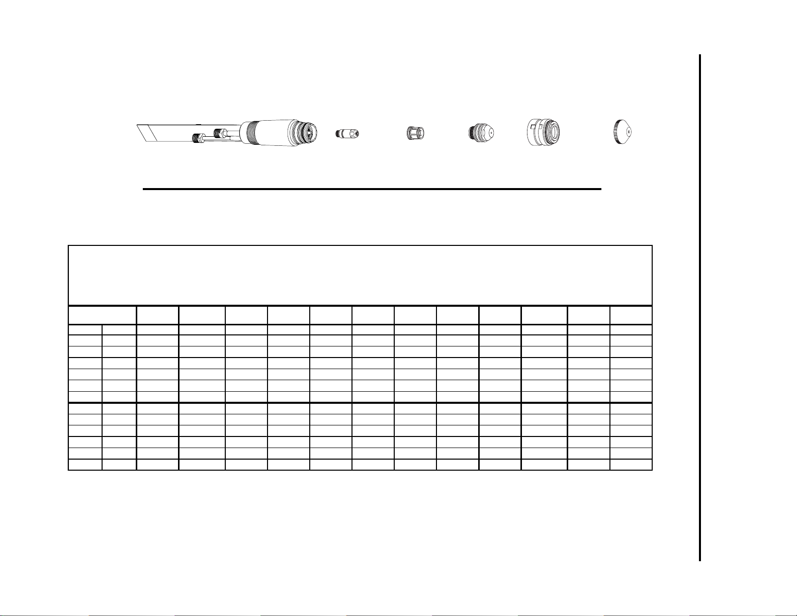
APPENDIX A-6 Man ual 0-2554
Torch Body
180˚ 9-6410
70˚ 9-6457
90˚ 9-6459
Electrode
(See Chart)
Gas Distributor
(See Chart)
Tip
(See Chart)
Shield Cup Body
20-1002*
End Cap
(See Chart)
APPENDIX 2: CUTTING SPEED CHARTS FOR
Art # A-02186
*or Ohmic Clip Shield Cup Body 20-1427
NOTE:
If using a torch height control which offers an ohmic sensing feature, select a shield cup body with an ohmic clip tab.
Use catalog # 20-1427 for normal cutting and catalog 20-1428 for cutting underwater.
US M easurement s
Nitrogen Plasma Cutting Data Chart
Maxim izer 300 To r ch
Aluminum
Nitrogen Plasma / Water Secondary
Material
Thickness
inches Gauge Cat . No. Cat. No. Cat. No. Cat. No. amps vdc inches/min inches psi gal/hr seconds inches
1/8 10 20-1023 20-0008 20-1031 20-100 4 100 160 225 0.188 70 8 0.00 0.375
3/16 7 20-1023 20-0008 20-1031 20-1004 100 160 150 0.188 70 8 0.25 0.375
1/4 20-1023 20-0008 20-1031 20-1004 100 160 80 0.188 70 8 0.25 0.375
3/8 20-1023 20-0008 20-1031 20-1004 100 160 50 0.188 70 8 0.25 0.375
1/2 20-1023 20-0008 20-1031 20-1004 100 165 25 0.188 70 8 0.37 0.375
5/8 20-1023 20-0008 20-1031 20-1004 100 175 20 0.188 70 8 0.50 0.375
3/16 20-1023 20-0008 20-1032 20-1004 150 145 175 0.188 70 9 0.25 0.375
1/4 20-1023 20-0008 20-1032 20-1004 150 150 130 0.188 70 9 0.25 0.375
3/8 20-1023 20-0008 20-1032 20-1004 150 150 95 0.188 70 9 0.25 0.375
1/2 20-1023 20-0008 20-1032 20-1004 150 150 65 0.188 70 9 0.35 0.375
5/8 20-1023 20-0008 20-1032 20-1004 150 155 40 0.188 70 9 0.35 0.375
3/4 20-1023 20-0008 20-1032 20-1004 150 162 20 0.188 70 9 0.50 0.500
Elec t rode
Gas
Distributor
Tip End Ca p Amperage
Output
Volts
Speed Standoff
Plas ma
Pressure
Secondary
Flow
Pierce
Delay
Pierce
Height
MERLIN 15XC SYSTEMS (continued)
Page 51

Manual 0-2554 A-7 APPENDIX
Material
Thickness
mm
3.2
4.8
6.4
9.5
12.7
15.9
4.8
6.4
9.5
12.7
15.9
19.1
Metr ic Measurements
Nitrogen Plasma Cutting Data Chart
Maxim i zer 300 T orch
Aluminum
Nitrogen Plasma / Water Secondary
Electrode
Cat. No. Cat. No. Cat. No. Cat. No. amps vdc m / min mm bar gal/hr sec
20-1023 20-0008 20-1031 20-1004 100 160 5.72 4.78 4.83 8.00 0.00 9.53
20-1023 20-0008 20-1031 20-1004 100 160 3.81 4.78 4.83 8.00 0.25 9.53
20-1023 20-0008 20-1031 20-1004 100 160 2.03 4.78 4.83 8.00 0.25 9.53
20-1023 20-0008 20-1031 20-1004 100 160 1.27 4.78 4.83 8.00 0.25 9.53
20-1023 20-0008 20-1031 20-1004 100 165 0.64 4.78 4.83 8.00 0.37 9.53
20-1023 20-0008 20-1031 20-1004 100 175 0.51 4.78 4.83 8.00 0.50 9.53
20-1023 20-0008 20-1032 20-1004 150 145 4.45 4.78 4.83 9.00 0.25 9.53
20-1023 20-0008 20-1032 20-1004 150 150 3.30 4.78 4.83 9.00 0.25 9.53
20-1023 20-0008 20-1032 20-1004 150 150 2.41 4.78 4.83 9.00 0.25 9.53
20-1023 20-0008 20-1032 20-1004 150 150 1.65 4.78 4.83 9.00 0.35 9.53
20-1023 20-0008 20-1032 20-1004 150 155 1.02 4.78 4.83 9.00 0.35 9.53
20-1023 20-0008 20-1032 20-1004 150 162 0.51 4.78 4.83 9.00 0.50 12.70
Gas
Distributor
Tip End Cap Amperage
Output
Volts
Speed Standoff
Plasma
Pressure
Secondary
Flow
Pierce
Delay
Pierce
Height
mm
NOTES
1. Recommended plasma pressure setting for 60 ft (18.3 m) total hose length (extension plus leads). For every 10 ft (3 m) of
additional hose length add 2.5 psi (0.17 bar) to the plasma pressure setting.
2. Piercing materials 3/4 inch (19.1 mm) and over may shorten torch consumable parts life.
Page 52

APPENDIX A-8 Man ual 0-2554
Torch Body
180˚ 9-6410
70˚ 9-6457
90˚ 9-6459
Electrode
(See Chart)
Gas Distributor
(See Chart)
Tip
(See Chart)
Shield Cup Body
20-1002*
End Cap
(See Chart)
APPENDIX 2: CUTTING SPEED CHARTS FOR
Art # A-02186
*or Ohmic Clip Shield Cup Body 20-1427
NOTE:
If using a torch height control which offers an ohmic sensing feature, select a shield cup body with an ohmic clip tab.
Use catalog # 20-1427 for normal cutting and catalog 20-1428 for cutting underwater.
US M easurement s
Ai r Plasma Cutting Dat a Chart
Maxi m i z er 300 Torch
Mild Steel
Ai r Plasma / A ir Seco ndary
Material
Thickness
inches Gauge Cat . No. Cat. No. Cat. No. Cat. No. amps vdc i nches/ min i n ches psi psi seconds inches
0.035 20 20-1018 20-0008 20-1030 20-1003 50 150 800 0.125 60 15 0.00 0.250
1/16 16 20-1018 20-0008 20-1030 20-1003 50 150 350 0.250 60 15 0.00 0.250
1/8 10 20-1018 20-0008 20-1030 20-1003 50 155 165 0.250 60 15 0.00 0.250
3/16 7 20-1018 20-0008 20-1030 20-1003 50 155 100 0.250 60 15 0.25 0.375
1/4 20-1018 20-0008 20-1030 20-1003 50 160 50 0.250 60 15 0.50 0.375
1/16 16 20-1018 20-0008 20-1031 20-1004 100 155 450 0.188 70 20 0.00 0.375
1/8 10 20-1018 20-0008 20-1031 20-1004 100 155 250 0.188 70 20 0.00 0.375
3/16 7 20-1018 20-0008 20-1031 20-1004 100 155 190 0.188 70 20 0.00 0.375
1/4 20-1018 20-0008 20-1031 20-1004 100 160 120 0.188 70 20 0.00 0.375
3/8 20-1018 20-0008 20-1031 20-1004 100 160 75 0.188 70 20 0.50 0.250
1/2 20-1018 20-0008 20-1031 20-1004 100 160 60 0.188 70 20 0.50 0.250
5/8 20-1018 20-0008 20-1031 20-1004 100 160 45 0.250 70 20 0.50 0.375
1/4 20-1018 20-0008 20-1032 20-1004 150 150 125 0.250 70 20 0.00 0.375
3/8 20-1018 20-0008 20-1032 20-1004 150 150 100 0.250 70 20 0.50 0.500
1/2 20-1018 20-0008 20-1032 20-1004 150 155 80 0.312 70 20 0.50 0.500
5/8 20-1018 20-0008 20-1032 20-1004 150 155 60 0.312 70 20 0.50 0.500
3/4 20-1018 20-0008 20-1032 20-1004 150 155 45 0.312 70 20 0.50 0.500
1 20-1018 20-0008 20-1032 20-1004 150 165 30 0.312 70 20 0.50 0.500
Electrode
Gas
Distributor
Tip End Cap Amperage
Output
Volts
Speed Standoff
Plasma
Pressure
Secondary
Pressure
Pierce
Delay
Pierce
Height
MERLIN 15XC SYSTEMS (continued)
Page 53

Manual 0-2554 A-9 APPENDIX
Material
Thickness
mm
0.9
1.6
3.2
4.8
6.4
1.6
3.2
4.8
6.4
9.5
12.7
15.9
6.4
9.5
12.7
15.9
19.1
25.4
Metr ic Measur em ents
Air Plasma Cutting Data Chart
Maxi m izer 300 Torch
Mild S teel
Air Plasma / Air Secondary
Electrode
Cat. No. Cat . No. Cat . No. Cat. No. amps vdc m / min mm bar bar seconds
20-1018 20-0008 20-1030 20-1003 50 150 20.32 3.18 4.14 1.03 0.00 6.35
20-1018 20-0008 20-1030 20-1003 50 150 8.89 6.35 4.14 1.03 0.00 6.35
20-1018 20-0008 20-1030 20-1003 50 155 4.19 6.35 4.14 1.03 0.00 6.35
20-1018 20-0008 20-1030 20-1003 50 155 2.54 6.35 4.14 1.03 0.25 9.53
20-1018 20-0008 20-1030 20-1003 50 160 1.27 6.35 4.14 1.03 0.50 9.53
20-1018 20-0008 20-1031 20-1004 100 155 11.43 4.78 4.83 1.38 0.00 9.53
20-1018 20-0008 20-1031 20-1004 100 155 6.35 4.78 4.83 1.38 0.00 9.53
20-1018 20-0008 20-1031 20-1004 100 155 4.83 4.78 4.83 1.38 0.00 9.53
20-1018 20-0008 20-1031 20-1004 100 160 3.05 4.78 4.83 1.38 0.00 9.53
20-1018 20-0008 20-1031 20-1004 100 160 1.91 4.78 4.83 1.38 0.50 6.35
20-1018 20-0008 20-1031 20-1004 100 160 1.52 4.78 4.83 1.38 0.50 6.35
20-1018 20-0008 20-1031 20-1004 100 160 1.14 6.35 4.83 1.38 0.50 9.53
20-1018 20-0008 20-1032 20-1004 150 150 3.18 6.35 4.83 1.38 0.00 9.53
20-1018 20-0008 20-1032 20-1004 150 150 2.54 6.35 4.83 1.38 0.50 12.70
20-1018 20-0008 20-1032 20-1004 150 155 2.03 7.92 4.83 1.38 0.50 12.70
20-1018 20-0008 20-1032 20-1004 150 155 1.52 7.92 4.83 1.38 0.50 12.70
20-1018 20-0008 20-1032 20-1004 150 155 1.14 7.92 4.83 1.38 0.50 12.70
20-1018 20-0008 20-1032 20-1004 150 165 0.76 7.92 4.83 1.38 0.50 12.70
Gas
Distributor
Tip End Cap Amperage
Output
Volts
Speed Standoff
Plasma
Pressure
Secondary
Pressure
Pierce
Delay
Pierce
Height
mm
NOTES
1. Recommended plasma pressure setting for 60 ft (18.3 m) total hose length (extension plus leads). For every 10 ft (3 m) of additional
hose length add 2.5 psi (0.17 bar) to the plasma pressure setting.
2. Recommended secondary pressure setting for 60 ft (18.3 m) total hose length (extension plus leads). For every 10 ft (3 m) of additional hose length add 1.0 psi (0.07 bar) to the secondary pressure setting.
3. Piercing materials 3/4 inch (19.1 mm) and over may shorten torch consumable parts life.
Page 54

APPENDIX A-10 Manual 0-2554
Torch Body
180˚ 9-6410
70˚ 9-6457
90˚ 9-6459
Electrode
(See Chart)
Gas Distributor
(See Chart)
Tip
(See Chart)
Shield Cup Body
No. 20-1029*
End Cap
(See Chart)
APPENDIX 2: CUTTING SPEED CHARTS FOR
MERLIN 15XC SYSTEMS (continued)
Art # A-02704
* or Ohmic Clip Shield Cup Body for Underwater Cutting No. 20-1428
NOTE:
If using a torch height control which offers an ohmic sensing feature, select a shield cup body with an ohmic clip tab.
Use catalog # 20-1427 for normal cutting and catalog 20-1428 for cutting underwater.
US M easu r em en ts
Air Plasma Cutting Data Chart
Maximizer 300 Torch
Mi l d St eel - Underw ater (Wat er Table)
Air Plasma / Air Second ary
Material
Thickness
inches Gauge Cat. No. Cat. No. Cat. No. Cat . No. amps vdc inches/min i nches psi psi seconds inches
1/16 16 20- 10 18 20-0008 20-1031 20-1028 100 145 400 0.188 70 50 0.00 0.200
1/8 10 20-1018 20-0008 20-1031 20-1028 100 145 225 0.188 70 50 0.20 0.200
3/16 7 20-1018 20-0008 20-1031 20-1028 100 150 135 0.188 70 50 0.20 0.200
1/4 20-1018 20-0008 20-1031 20-1028 100 155 105 0.188 70 50 0.20 0.200
3/8 20-1018 20-0008 20-1031 20-1028 100 160 75 0.250 70 50 0.30 0.300
1/4 20-1018 20-0008 20-1032 20-1028 150 140 160 0.250 70 50 0.00 0.250
3/8 20-1018 20-0008 20-1032 20-1028 150 150 90 0.250 70 50 0.20 0.375
1/2 20-1018 20-0008 20-1032 20-1028 150 160 65 0.250 70 50 0.50 0.375
5/8 20-1018 20-0008 20-1032 20-1028 150 165 45 0.250 70 50 0.50 0.500
3/4 20-1018 20-0008 20-1032 20-1028 150 170 30 0.250 70 50 0.75 0.500
Electrode
Gas
Distributor
Tip End Cap Amperage
Output
Volts
Speed Standoff
Plasma
Pressure
Secondary
Pressure
Pierce
Delay
Pierce
Height
Page 55

Manual 0-2554 A-11 APPENDIX
Material
Thickness
mm
1.6
3.2
4.8
6.4
9.5
6.4
9.5
12.7
15.9
19.1
Metr i c Meas u r em en t s
Ai r P lasma Cu tt i ng Dat a C hart
Maximizer 300 Tor ch
Mild St eel - Underwater (Water Table)
Air Plasma / Air Secondary
Electrode
Cat. No. Cat. No. Cat. No. Cat. No. amps vdc m / min mm bar bar seconds
20-1018 20-0008 20-1031 20-1028 100 145 10.16 4.78 4.83 3.45 0.00 5.08
20-1018 20-0008 20-1031 20-1028 100 145 5.72 4.78 4.83 3.45 0.20 5.08
20-1018 20-0008 20-1031 20-1028 100 150 3.43 4.78 4.83 3.45 0.20 5.08
20-1018 20-0008 20-1031 20-1028 100 155 2.67 4.78 4.83 3.45 0.20 5.08
20-1018 20-0008 20-1031 20-1028 100 160 1.91 6.35 4.83 3.45 0.30 7.62
20-1018 20-0008 20-1032 20-1028 150 140 4.06 6.35 4.83 3.45 0.00 6.35
20-1018 20-0008 20-1032 20-1028 150 150 2.29 6.35 4.83 3.45 0.20 9.53
20-1018 20-0008 20-1032 20-1028 150 160 1.65 6.35 4.83 3.45 0.50 9.53
20-1018 20-0008 20-1032 20-1028 150 165 1.14 6.35 4.83 3.45 0.50 12.70
20-1018 20-0008 20-1032 20-1028 150 170 0.76 6.35 4.83 3.45 0.75 12.70
Gas
Distributor
Tip End Ca p A m pe rage
Output
Volts
Speed Standoff
Plasma
Pressure
Secondary
Pressure
Pierce
Delay
Pierce
Height
mm
NOTES
1. Recommended plasma pressure setting for 60 ft (18.3 m) total hose length (extension plus leads). For every 10 ft (3 m) of additional
hose length add 2.5 psi (0.17 bar) to the plasma pressure setting.
2. Recommended secondary pressure setting for 60 ft (18.3 m) total hose length (extension plus leads). For every 10 ft (3 m) of additional hose length add 1.0 psi (0.07 bar) to the secondary pressure setting.
3. Piercing materials 3/4 inch (19.1 mm) and over may shorten torch consumable parts life.
Page 56

APPENDIX A-12 Manual 0-2554
Torch Body
180˚ 9-6410
70˚ 9-6457
90˚ 9-6459
Electrode
(See Chart)
Gas Distributor
(See Chart)
Tip
(See Chart)
Shield Cup Body
20-1002*
End Cap
(See Chart)
APPENDIX 2: CUTTING SPEED CHARTS FOR
Art # A-02186
*or Ohmic Clip Shield Cup Body 20-1427
NOTE:
If using a torch height control which offers an ohmic sensing feature, select a shield cup body with an ohmic clip tab.
Use catalog # 20-1427 for normal cutting and catalog 20-1428 for cutting underwater.
US M easurements
Oxygen Plasma Cutting Data Chart
Maxi m i zer 3 00 Torch
Mild Steel
Oxygen P l asma / A i r Secondary
Material
Thickness
inches Gauge Cat. No. Cat. No. Cat . No. Cat . No. amps vdc inches/min i nches psi psi seconds i nches
0.035 20 20-1015 20-0008 20-1030 20-1003 50 125 800 0.125 60 15 0.00 0.125
1/16 16 20-1015 20-0008 20-1030 20-1003 50 130 350 0.188 60 15 0.20 0.250
1/8 10 20-1015 20-0008 20-1030 20-1003 50 135 160 0.188 60 15 0.50 0.250
3/16 7 20-1015 20-0008 20-1030 20-1003 50 140 105 0.188 60 15 0.50 0.250
1/4 20-1015 20-0008 20-1030 20-1003 50 140 75 0.188 60 15 0.75 0.250
1/16 16 20-1015 20-0008 20-1031 20-1004 100 125 500 0.125 70 20 0.00 0.250
1/8 10 20-1015 20-0008 20-1031 20-1004 100 125 250 0.250 70 20 0.00 0.250
3/16 7 20-1015 20-0008 20-1031 20-1004 100 125 190 0.250 70 20 0.00 0.250
1/4 20-1015 20-0008 20-1031 20-1004 100 125 115 0.250 70 20 0.00 0.250
3/8 20-1015 20-0008 20-1031 20-1004 100 130 65 0.250 70 20 0.25 0.375
1/2 20-1015 20-0008 20-1031 20-1004 100 132 55 0.250 70 20 0.50 0.500
5/8 20-1015 20-0008 20-1031 20-1004 100 132 45 0.250 70 20 0.50 0.500
1/4 20-1016 20-0008 20-1032 20-1004 150 125 175 0.188 70 20 0.00 0.250
3/8 20-1016 20-0008 20-1032 20-1004 150 125 110 0.188 70 20 0.25 0.375
1/2 20-1016 20-0008 20-1032 20-1004 150 130 65 0.250 70 20 0.25 0.375
5/8 20-1016 20-0008 20-1032 20-1004 150 130 40 0.250 70 20 0.25 0.375
3/4 20-1016 20-0008 20-1032 20-1004 150 130 30 0.250 70 20 0.50 0.500
1 20-1016 20-0008 20-1032 20-1004 150 130 25 0.250 70 20 0.50 0.500
Electrode
Gas
Distributor
Tip End Cap Amperage
Output
Volts
Speed Standoff
Plasma
Pressure
Secondary
Pressure
Pierce
Delay
Pierce
Height
MERLIN 15XC SYSTEMS (continued)
Page 57

Manual 0-2554 A-13 APPENDIX
Material
Thickness
mm
0.9
1.6
3.2
4.8
6.4
1.6
3.2
4.8
6.4
9.5
12.7
15.9
6.4
9.5
12.7
15.9
19.1
25.4
Metric Measurements
Oxygen Plasma Cutting Data Chart
Maxi m izer 300 Torch
Mild Steel
Oxygen P l asma / Air Secon dary
Electrode
Cat. No. Cat. No. Cat. No. Cat. No. amps vdc m / min mm bar bar seconds mm
20-1015 20-0008 20-1030 20-1003 50 125 20.32 3.18 4.14 1.03 0.00 3.18
20-1015 20-0008 20-1030 20-1003 50 130 8.89 4.78 4.14 1.03 0.20 6.35
20-1015 20-0008 20-1030 20-1003 50 135 4.06 4.78 4.14 1.03 0.50 6.35
20-1015 20-0008 20-1030 20-1003 50 140 2.67 4.78 4.14 1.03 0.50 6.35
20-1015 20-0008 20-1030 20-1003 50 140 1.91 4.78 4.14 1.03 0.75 6.35
20-1015 20-0008 20-1031 20-1004 100 125 12.70 3.18 4.83 1.38 0.00 6.35
20-1015 20-0008 20-1031 20-1004 100 125 6.35 6.35 4.83 1.38 0.00 6.35
20-1015 20-0008 20-1031 20-1004 100 125 4.83 6.35 4.83 1.38 0.00 6.35
20-1015 20-0008 20-1031 20-1004 100 125 2.92 6.35 4.83 1.38 0.00 6.35
20-1015 20-0008 20-1031 20-1004 100 130 1.65 6.35 4.83 1.38 0.25 9.53
20-1015 20-0008 20-1031 20-1004 100 132 1.40 6.35 4.83 1.38 0.50 12.70
20-1015 20-0008 20-1031 20-1004 100 132 1.14 6.35 4.83 1.38 0.50 12.70
20-1016 20-0008 20-1032 20-1004 150 125 4.45 4.78 4.83 1.38 0.00 6.35
20-1016 20-0008 20-1032 20-1004 150 125 2.79 4.78 4.83 1.38 0.25 9.53
20-1016 20-0008 20-1032 20-1004 150 130 1.65 6.35 4.83 1.38 0.25 9.53
20-1016 20-0008 20-1032 20-1004 150 130 1.02 6.35 4.83 1.38 0.25 9.53
20-1016 20-0008 20-1032 20-1004 150 130 0.76 6.35 4.83 1.38 0.50 12.70
20-1016 20-0008 20-1032 20-1004 150 130 0.64 6.35 4.83 1.38 0.50 12.70
Gas
Distributor
Tip End Cap Amperage
Output
Volts
Speed Standoff
Plasma
Pressure
Secondary
Pressure
Pierce
Delay
Pierce
Height
NOTES
1. Recommended plasma pressure setting for 60 ft (18.3 m) total hose length (extension plus leads). For every 10 ft (3 m) of additional
hose length add 2.5 psi (0.17 bar) to the plasma pressure setting.
2. Recommended secondary pressure setting for 60 ft (18.3 m) total hose length (extension plus leads). For every 10 ft (3 m) of additional hose length add 1.0 psi (0.07 bar) to the secondary pressure setting.
3. Piercing materials 3/4 inch (19.1 mm) and over may shorten torch consumable parts life.
Page 58
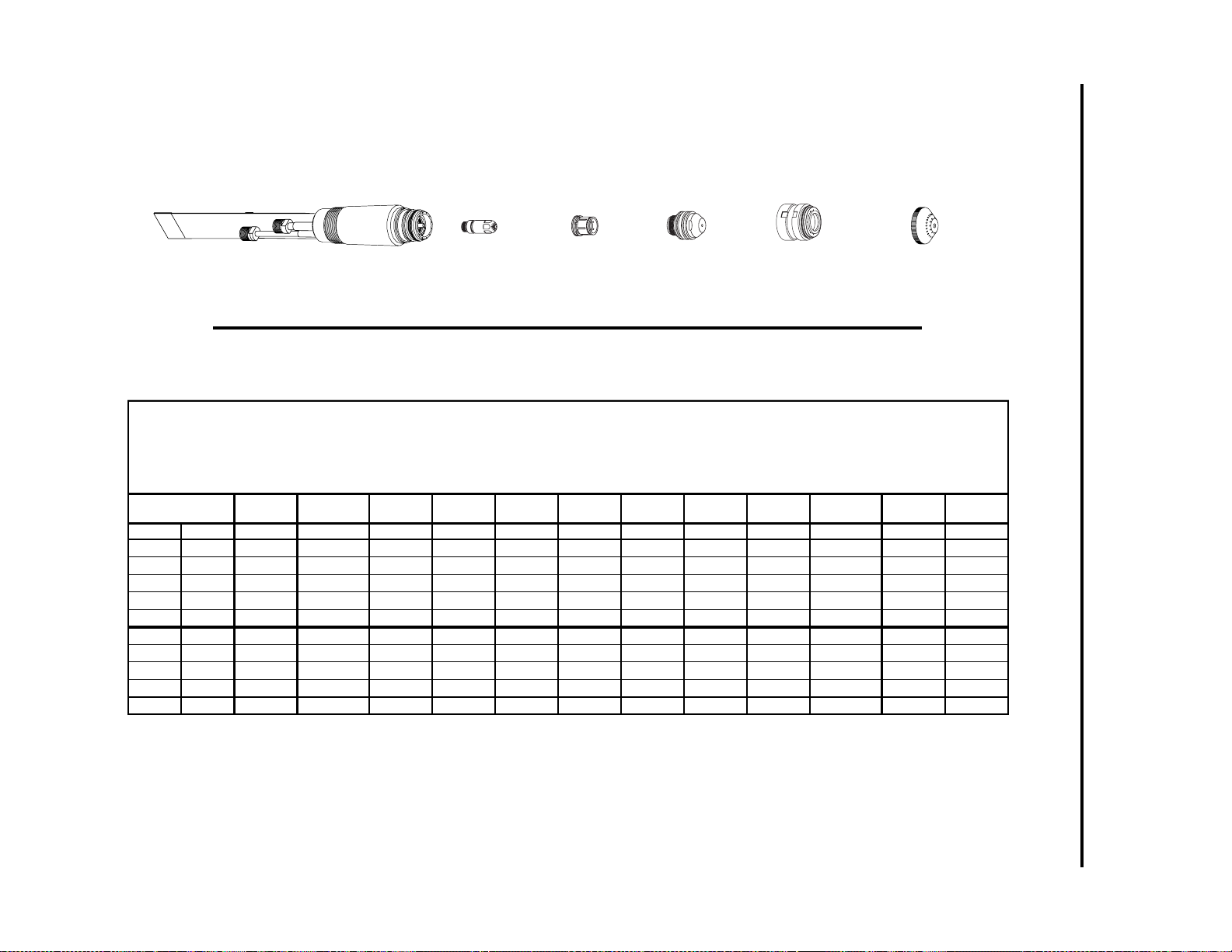
APPENDIX A-14 Manual 0-2554
Torch Body
180˚ 9-6410
Art # A-02704
70˚ 9-6457
90˚ 9-6459
Electrode
(See Chart)
Gas Distributor
(See Chart)
* or Ohmic Clip Shield Cup Body for Underwater Cutting No. 20-1428
Tip
(See Chart)
Shield Cup Body
No. 20-1029*
End Cap
(See Chart)
NOTE:
If using a torch height control which offers an ohmic sensing feature, select a shield cup body with an ohmic clip tab.
Use catalog # 20-1427 for normal cutting and catalog 20-1428 for cutting underwater.
US M eas uremen t s
Oxyg en Plasma Cuttin g Data Chart
Maximi zer 300 T orch
Mil d Steel - Und er water (Water Table)
Oxyg en Plasma / A i r Second ar y
Material
Thickness
inches Gauge Cat. No. Cat. No. Cat. No. Cat . No. amps vdc inches/min inches psi psi seconds inches
1/16 16 20-1015 20-0008 20-1031 20-1028 100 125 400 0.188 70 50 0.00 0.250
1/8 10 20-1015 20-0008 20-1031 20-1028 100 125 275 0.188 70 50 0.00 0.250
3/16 7 20-1015 20-0008 20-1031 20-1028 100 130 185 0.188 70 50 0.00 0.250
1/4 20-1015 20-0008 20-1031 20-1028 100 130 125 0.188 70 50 0.00 0.250
3/8 20-1015 20-0008 20-1031 20-1028 100 130 75 0.188 70 50 0.25 0.250
1/4 20-1016 20-0008 20-1032 20-1028 150 121 150 0.188 70 50 0.10 0.250
3/8 20-1016 20-0008 20-1032 20-1028 150 125 100 0.188 70 50 0.10 0.250
1/2 20-1016 20-0008 20-1032 20-1028 150 130 65 0.188 70 50 0.20 0.250
5/8 20-1016 20-0008 20-1032 20-1028 150 135 55 0.188 70 50 0.20 0.250
3/4 20-1016 20-0008 20-1032 20-1028 150 140 40 0.188 70 50 0.50 0.500
Electrode
Gas
Distributor
Tip End Cap Amperage
Output
Volts
Speed Standoff
Plasma
Pressure
Secondary
Pressure
Pierce
Delay
Pierce
Height
APPENDIX 2: CUTTING SPEED CHARTS FOR
MERLIN 15XC SYSTEMS (continued)
Page 59
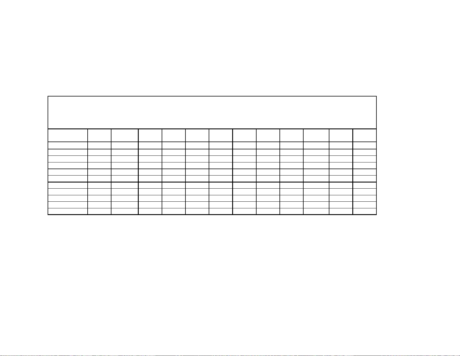
Manual 0-2554 A-15 APPENDIX
Material
Thickness
mm
1.6
3.2
4.8
6.4
9.5
6.4
9.5
12.7
15.9
19.1
Metric Measurements
Oxyg en Plasma Cu tting D at a C hart
Maximizer 300 Torch
Mil d Steel - Underw at er (Wat er Table)
Oxyg en Plasma / Ai r Seco ndary
Electrode
Cat. No. Cat. No. Cat . No. Cat. No. amps vdc m / min mm bar bar seconds
20-1015 20-0008 20-1031 20-1028 100 125 10.16 4.78 4.83 3.45 0.00 6.35
20-1015 20-0008 20-1031 20-1028 100 125 6.99 4.78 4.83 3.45 0.00 6.35
20-1015 20-0008 20-1031 20-1028 100 130 4.70 4.78 4.83 3.45 0.00 6.35
20-1015 20-0008 20-1031 20-1028 100 130 3.18 4.78 4.83 3.45 0.00 6.35
20-1015 20-0008 20-1031 20-1028 100 130 1.91 4.78 4.83 3.45 0.25 6.35
20-1016 20-0008 20-1032 20-1028 150 121 3.81 4.78 4.83 3.45 0.10 6.35
20-1016 20-0008 20-1032 20-1028 150 125 2.54 4.78 4.83 3.45 0.10 6.35
20-1016 20-0008 20-1032 20-1028 150 130 1.65 4.78 4.83 3.45 0.20 6.35
20-1016 20-0008 20-1032 20-1028 150 135 1.40 4.78 4.83 3.45 0.20 6.35
20-1016 20-0008 20-1032 20-1028 150 140 1.02 4.78 4.83 3.45 0.50 12.70
Gas
Distributor
Tip End Ca p A mperage
Output
Volts
Speed Standoff
Plasma
Pressure
Secondary
Pressure
Pierce
Delay
Pierce
Height
mm
NOTES
1. Recommended plasma pressure setting for 60 ft (18.3 m) total hose length (extension plus leads). For every 10 ft (3 m) of additional
hose length add 2.5 psi (0.17 bar) to the plasma pressure setting.
2. Recommended secondary pressure setting for 60 ft (18.3 m) total hose length (extension plus leads). For every 10 ft (3 m) of additional hose length add 1.0 psi (0.07 bar) to the secondary pressure setting.
3. Piercing materials 3/4 inch (19.1 mm) and over may shorten torch consumable parts life.
Page 60

APPENDIX A-16 Manual 0-2554
Torch Body
180˚ 9-6410
70˚ 9-6457
90˚ 9-6459
Electrode
(See Chart)
Gas Distributor
(See Chart)
Tip
(See Chart)
Shield Cup Body
20-1002*
End Cap
(See Chart)
APPENDIX 2: CUTTING SPEED CHARTS FOR
Art # A-02186
*or Ohmic Clip Shield Cup Body 20-1427
NOTE:
If using a torch height control which offers an ohmic sensing feature, select a shield cup body with an ohmic clip tab.
Use catalog # 20-1427 for normal cutting and catalog 20-1428 for cutting underwater.
US M easurements
Ai r Plasma Cu t t i ng Data Chart
Maximizer 300 Torch
St ainless Steel
Ai r P lasm a / A i r S eco n dary
Material
Thickness
inches Gauge Cat. No. Cat. No. Cat. No. Cat. No. amps vdc inches/min inches psi psi seconds inches
0.035 20 20-1018 20-0008 20-1030 20-1003 50 145 400 0.125 60 50 0.00 0.188
1/16 16 20-1018 20-0008 20-1030 20-1003 50 155 250 0.188 60 50 0.00 0.250
1/8 10 20-1018 20-0008 20-1030 20-1003 50 165 50 0.188 60 50 0.00 0.250
3/16 7 20-1018 20-0008 20-1030 20-1003 50 170 18 0.188 60 50 0.00 0.250
1/4 20-1018 20-0008 20-1030 20-1003 50 180 12 0.188 60 50 0.25 0.250
1/16 16 20-1018 20-0008 20-1031 20-1004 100 140 400 0.188 70 20 0.00 0.200
1/8 10 20-1018 20-0008 20-1031 20-1004 100 155 200 0.188 70 20 0.10 0.200
3/16 7 20-1018 20-0008 20-1031 20-1004 100 155 125 0.188 70 20 0.10 0.200
1/4 20-1018 20-0008 20-1031 20-1004 100 160 100 0.188 70 20 0.25 0.200
3/8 20-1018 20-0008 20-1031 20-1004 100 160 60 0.188 70 20 0.30 0.200
1/2 20-1018 20-0008 20-1031 20-1004 100 165 35 0.188 70 20 0.50 0.200
5/8 20-1018 20-0008 20-1031 20-1004 100 170 20 0.188 70 20 1.00 0.200
1/4 20-1018 20-0008 20-1032 20-1004 150 135 150 0.250 70 20 0.00 0.375
3/8 20-1018 20-0008 20-1032 20-1004 150 145 100 0.250 70 20 0.00 0.375
1/2 20-1018 20-0008 20-1032 20-1004 150 150 65 0.250 70 20 0.25 0.375
5/8 20-1018 20-0008 20-1032 20-1004 150 150 40 0.250 70 20 0.25 0.375
3/4 20-1018 20-0008 20-1032 20-1004 150 160 30 0.312 70 20 0.50 0.500
1 20-1018 20-0008 20-1032 20-1004 150 170 15 0.312 70 20 0.50 0.500
Electrode
Gas
Distributor
Tip End Ca p Amperage
Output
Volts
Speed Standoff
Plasma
Pressure
Secondary
Pressure
Pierce
Delay
Pierce
Height
MERLIN 15XC SYSTEMS (continued)
Page 61

Manual 0-2554 A-17 APPENDIX
Material
Thickness
mm
0.9
1.6
3.2
4.8
6.4
1.6
3.2
4.8
6.4
9.5
12.7
15.9
6.4
9.5
12.7
15.9
19.1
25.4
Metric Measurements
Air Plasma Cutting Data Chart
Maximizer 300 Torch
Stai nless Steel
Air Plasma / Air Second ary
Electrode
Cat. No. Cat. No. Cat. No. Cat . No. amps vdc m / min mm bar bar seconds mm
20-1018 20-0008 20-1030 20-1003 50 145 10.16 3.18 4.14 3.45 0.00 4.78
20-1018 20-0008 20-1030 20-1003 50 155 6.35 4.78 4.14 3.45 0.00 6.35
20-1018 20-0008 20-1030 20-1003 50 165 1.27 4.78 4.14 3.45 0.00 6.35
20-1018 20-0008 20-1030 20-1003 50 170 0.46 4.78 4.14 3.45 0.00 6.35
20-1018 20-0008 20-1030 20-1003 50 180 0.30 4.78 4.14 3.45 0.25 6.35
20-1018 20-0008 20-1031 20-1004 100 140 10.16 4.78 4.83 1.38 0.00 5.08
20-1018 20-0008 20-1031 20-1004 100 155 5.08 4.78 4.83 1.38 0.10 5.08
20-1018 20-0008 20-1031 20-1004 100 155 3.18 4.78 4.83 1.38 0.10 5.08
20-1018 20-0008 20-1031 20-1004 100 160 2.54 4.78 4.83 1.38 0.25 5.08
20-1018 20-0008 20-1031 20-1004 100 160 1.52 4.78 4.83 1.38 0.30 5.08
20-1018 20-0008 20-1031 20-1004 100 165 0.89 4.78 4.83 1.38 0.50 5.08
20-1018 20-0008 20-1031 20-1004 100 170 0.51 4.78 4.83 1.38 1.00 5.08
20-1018 20-0008 20-1032 20-1004 150 135 3.81 6.35 4.83 1.38 0.00 9.53
20-1018 20-0008 20-1032 20-1004 150 145 2.54 6.35 4.83 1.38 0.00 9.53
20-1018 20-0008 20-1032 20-1004 150 150 1.65 6.35 4.83 1.38 0.25 9.53
20-1018 20-0008 20-1032 20-1004 150 150 1.02 6.35 4.83 1.38 0.25 9.53
20-1018 20-0008 20-1032 20-1004 150 160 0.76 7.92 4.83 1.38 0.50 12.70
20-1018 20-0008 20-1032 20-1004 150 170 0.38 7.92 4.83 1.38 0.50 12.70
Gas
Distributor
Tip End Cap Amperage
Output
Volts
Speed Standoff
Plasma
Pressure
Secondary
Pressure
Pierce
Delay
Pierce
Height
NOTES
1. Recommended plasma pressure setting for 60 ft (18.3 m) total hose length (extension plus leads). For every 10 ft (3 m) of additional
hose length add 2.5 psi (0.17 bar) to the plasma pressure setting.
2. Recommended secondary pressure setting for 60 ft (18.3 m) total hose length (extension plus leads). For every 10 ft (3 m) of additional hose length add 1.0 psi (0.07 bar) to the secondary pressure setting.
3. Piercing materials 3/4 inch (19.1 mm) and over may shorten torch consumable parts life.
Page 62

APPENDIX A-18 Manual 0-2554
Torch Body
180˚ 9-6410
70˚ 9-6457
90˚ 9-6459
Electrode
(See Chart)
Gas Distributor
(See Chart)
Tip
(See Chart)
Shield Cup Body
No. 20-1029*
End Cap
(See Chart)
APPENDIX 2: CUTTING SPEED CHARTS FOR
MERLIN 15XC SYSTEMS (continued)
Art # A-02704
* or Ohmic Clip Shield Cup Body for Underwater Cutting No. 20-1428
NOTE:
If using a torch height control which offers an ohmic sensing feature, select a shield cup body with an ohmic clip tab.
Use catalog # 20-1427 for normal cutting and catalog 20-1428 for cutting underwater.
US M easu rements
Air Plasma Cutting Data Chart
Maximi zer 300 T orch
St ainless Steel - U nderwater (Water Table)
Air Plasma / Air Secondary
Material
Thickness
inches Gauge Cat . No. Cat . No. Cat. No. Cat. No. amps vdc inches/min inches psi psi seconds
1/16 16 20-1018 20-0008 20-1031 20-1028 100 145 400 0.188 70 50 0.00 0.200
1/8 10 20-1018 20-0008 20-1031 20-1028 100 150 200 0.188 70 50 0.10 0.200
3/16 7 20-1018 20-0008 20-1031 20-1028 100 150 130 0.188 70 50 0.20 0.200
1/4 20-1018 20-0008 20-1031 20-1028 100 150 70 0.188 70 50 0.30 0.200
3/8 20-1018 20-0008 20-1031 20-1028 100 160 50 0.188 70 50 0.50 0.200
1/4 20-1018 20-0008 20-1032 20-1028 150 145 150 0.250 70 50 0.00 0.375
3/8 20-1018 20-0008 20-1032 20-1028 150 150 100 0.250 70 50 0.00 0.375
1/2 20-1018 20-0008 20-1032 20-1028 150 155 80 0.250 70 50 0.25 0.375
5/8 20-1018 20-0008 20-1032 20-1028 150 160 50 0.250 70 50 0.25 0.375
3/4 20-1018 20-0008 20-1032 20-1028 150 165 25 0.250 70 50 0.50 0.500
Electrode
Gas
Distributor
Tip End Cap Ampe rage
Output
Volts
Speed Standoff
Plasma
Pressure
Secondary
Pressure
Pierce
Delay
Pierce
Height
inches
Page 63

Manual 0-2554 A-19 APPENDIX
Material
Thickness
mm
1.6
3.2
4.8
6.4
9.5
6.4
9.5
12.7
15.9
19.1
Metric Measurements
Air Plasma Cutting Data Chart
Maximizer 300 Torch
Stai nless Steel - U nderwater (W at er Table)
Air Plasma / Air Second ary
Electrode
Cat. No. Cat. No. Cat. No. Cat . No. amps vdc m / min mm bar bar seconds
20-1018 20-0008 20-1031 20-1028 100 145 10.16 4.78 4.83 3.45 0.00 5.08
20-1018 20-0008 20-1031 20-1028 100 150 5.08 4.78 4.83 3.45 0.10 5.08
20-1018 20-0008 20-1031 20-1028 100 150 3.30 4.78 4.83 3.45 0.20 5.08
20-1018 20-0008 20-1031 20-1028 100 150 1.78 4.78 4.83 3.45 0.30 5.08
20-1018 20-0008 20-1031 20-1028 100 160 1.27 4.78 4.83 3.45 0.50 5.08
20-1018 20-0008 20-1032 20-1028 150 145 3.81 6.35 4.83 3.45 0.00 9.53
20-1018 20-0008 20-1032 20-1028 150 150 2.54 6.35 4.83 3.45 0.00 9.53
20-1018 20-0008 20-1032 20-1028 150 155 2.03 6.35 4.83 3.45 0.25 9.53
20-1018 20-0008 20-1032 20-1028 150 160 1.27 6.35 4.83 3.45 0.25 9.53
20-1018 20-0008 20-1032 20-1028 150 165 0.64 6.35 4.83 3.45 0.50 12.70
Gas
Distributor
Tip End Cap Amperage
Output
Volts
Speed Standoff
Plasma
Pressure
Secondary
Pressure
Pierce
Delay
Pierce
Height
mm
NOTES
1. Recommended plasma pressure setting for 60 ft (18.3 m) total hose length (extension plus leads). For every 10 ft (3 m) of additional
hose length add 2.5 psi (0.17 bar) to the plasma pressure setting.
2. Recommended secondary pressure setting for 60 ft (18.3 m) total hose length (extension plus leads). For every 10 ft (3 m) of additional hose length add 1.0 psi (0.07 bar) to the secondary pressure setting.
3. Piercing materials 3/4 inch (19.1 mm) and over may shorten torch consumable parts life.
Page 64
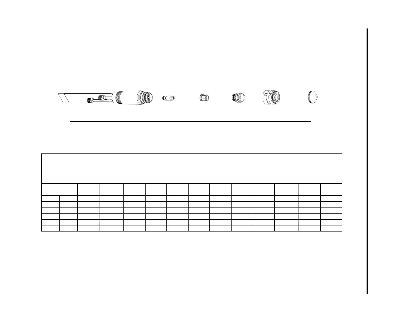
APPENDIX A-20 Manual 0-2554
Torch Body
180˚ 9-6410
70˚ 9-6457
90˚ 9-6459
Electrode
(See Chart)
Gas Distributor
(See Chart)
Tip
(See Chart)
Shield Cup Body
20-1002*
End Cap
(See Chart)
APPENDIX 2: CUTTING SPEED CHARTS FOR
MERLIN 15XC SYSTEMS (continued)
Art # A-02186
*or Ohmic Clip Shield Cup Body 20-1427
NOTE:
If using a torch height control which offers an ohmic sensing feature, select a shield cup body with an ohmic clip tab.
Use catalog # 20-1427 for normal cutting and catalog 20-1428 for cutting underwater.
US Measur em ents
Argon-Hydrogen Plasma Cutting Data Chart
Maxi m izer 300 T orch
Stai n l ess S t eel
Ar gon/Hydr ogen ( H-35) P l asma / Ni t r ogen Secon dary
Material
Thickness
inches G aug e Cat. No. Cat. No. Cat . No. Cat. No. amps vdc inches/min inches psi psi seconds
1/2 20-1025 20-0008 20-1032 20-1004 150 165 40 0.188 70 30 0.50 0.250
5/8 20-1025 20-0008 20-1032 20-1004 150 165 30 0.188 70 30 0.50 0.312
3/4 20-1025 20-0008 20-1032 20-1004 150 170 25 0.188 70 30 0.75 0.312
1 20-1025 20-0008 20-1032 20-1004 150 170 20 0.188 70 30 1.00 0.312
1 1/4 20-1025 20-0008 20-1032 20-1004 150 175 13 0.188 70 30 NR NR
Electrode
Gas
Distributor
Tip End Cap Amperage
Output
Volts
Speed Standoff
Plasma
Pressure
Secondary
Pressure
Pierce
Delay
Pierce
Height
inches
Page 65

Manual 0-2554 A-21 APPENDIX
Material
Thickness
mm
12.7
15.9
19.1
25.4
31.8
Metric Measurements
Argon-Hydrogen Plasma Cutting Data Chart
Maximizer 300 Torch
St a i nless S teel
Argon/Hydrogen (H-35) Plasma / Nitrogen Secondary
Electrode
Cat. No. Cat. No. Cat. No. Cat . No. amps vdc m / min mm bar bar seconds
20-1025 20-0008 20-1032 20-1004 150 165 1.02 4.78 4.83 2.07 0.50 6.35
20-1025 20-0008 20-1032 20-1004 150 165 0.76 4.78 4.83 2.07 0.50 7.92
20-1025 20-0008 20-1032 20-1004 150 170 0.64 4.78 4.83 2.07 0.75 7.92
20-1025 20-0008 20-1032 20-1004 150 170 0.51 4.78 4.83 2.07 1.00 7.92
20-1025 20-0008 20-1032 20-1004 150 175 0.33 4.78 4.83 2.07 NR NR
Gas
Distributor
Tip End Cap Ampe rage
Output
Volts
Speed Standoff
Plasma
Pressure
Secondary
Pressure
Pierce
Delay
Pierce
Height
mm
NOTES
1. Recommended plasma pressure setting for 60 ft (18.3 m) total hose length (extension plus leads). For every 10 ft (3 m) of additional
hose length add 2.5 psi (0.17 bar) to the plasma pressure setting.
2. Recommended secondary pressure setting for 60 ft (18.3 m) total hose length (extension plus leads). For every 10 ft (3 m) of additional hose length add 1.0 psi (0.07 bar) to the secondary pressure setting.
3. Piercing materials 3/4 inch (19.1 mm) and over may shorten torch consumable parts life.
Page 66
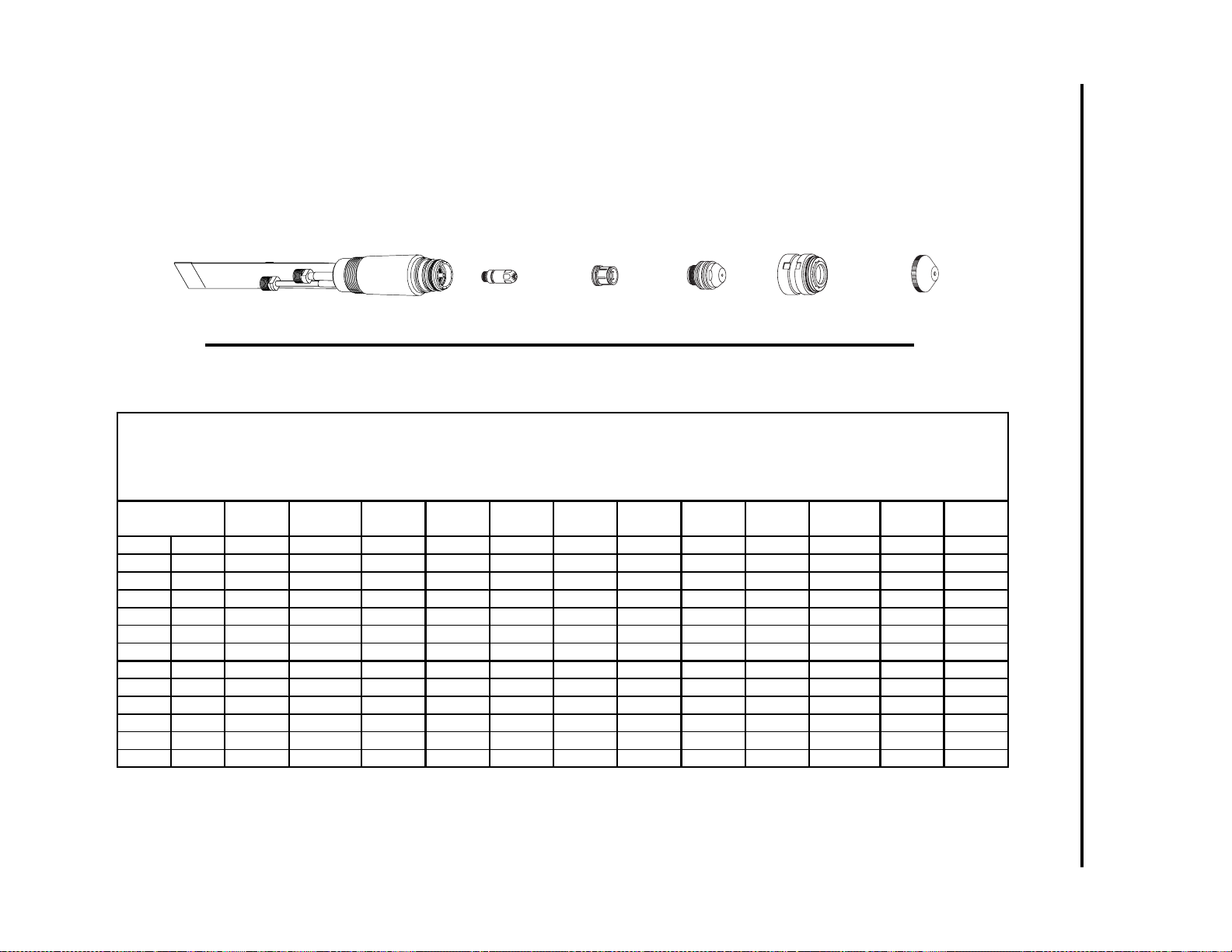
APPENDIX A-22 Manual 0-2554
Torch Body
180˚ 9-6410
Art # A-02186
70˚ 9-6457
90˚ 9-6459
Electrode
(See Chart)
Gas Distributor
(See Chart)
Tip
(See Chart)
*or Ohmic Clip Shield Cup Body 20-1427
Shield Cup Body
20-1002*
End Cap
(See Chart)
NOTE:
If using a torch height control which offers an ohmic sensing feature, select a shield cup body with an ohmic clip tab.
Use catalog # 20-1427 for normal cutting and catalog 20-1428 for cutting underwater.
US M easurement s
Ni t r o gen P l as ma Cutti ng Data Chart
Maxim izer 300 To r ch
St ai nless St eel
Ni t r o gen P l as ma / Water Second ary
Mater ial
Thickness
inches Gauge Cat. No. Cat. No. Cat. No. Cat. No. amps vdc inches/min inches psi gal/hr seconds
1/8 10 20-1023 20-0008 20-1031 20-1004 100 145 210 0.188 70 8 0.25 0.375
3/16 7 20-1023 20-0008 20-1031 20-1004 100 145 125 0.188 70 8 0.25 0.375
1/4 20-1023 20-0008 20-1031 20-1004 100 145 80 0.188 70 8 0.50 0.375
3/8 20-1023 20-0008 20-1031 20-1004 100 155 50 0.188 70 8 0.50 0.375
1/2 20-1023 20-0008 20-1031 20-1004 100 170 35 0.188 70 8 0.50 0.375
5/8 20-1023 20-0008 20-1031 20-1004 100 170 25 0.188 70 8 0.50 0.375
3/16 20-1023 20-0008 20-1032 20-1004 150 135 180 0.188 70 3 0.25 0.375
1/4 20-1023 20-0008 20-1032 20-1004 150 140 120 0.188 70 5 0.25 0.375
3/8 20-1023 20-0008 20-1032 20-1004 150 150 80 0.188 70 7 0.25 0.375
1/2 20-1023 20-0008 20-1032 20-1004 150 150 50 0.188 70 8 0.35 0.375
5/8 20-1023 20-0008 20-1032 20-1004 150 165 30 0.188 70 8 0.50 0.375
3/4 20-1023 20-0008 20-1032 20-1004 150 175 20 0.250 70 9 0.50 0.500
Electrode
Gas
Distributor
Tip End Cap Amperage
Output
Volts
Speed Standoff
Plasma
Pressure
Secondary
Flow
Pierce
Delay
APPENDIX 2: CUTTING SPEED CHARTS FOR
MERLIN 15XC SYSTEMS (continued)
Pierce
Height
inches
Page 67

Manual 0-2554 A-23 APPENDIX
Mater ial
Thickness
mm
3.2
4.8
6.4
9.5
12.7
15.9
4.8
6.4
9.5
12.7
15.9
19.1
Metric Measurements
Nitrog en P lasma Cuttin g Data Ch art
Maxim izer 300 To r ch
St ai nless St eel
Ni t r o gen P l as ma / Water Second ar y
Electrode
Cat. No. Cat. No. Cat. No. Cat. No. amps vdc m / min mm bar gal/hr seconds
20-1023 20-0008 20-1031 20-1004 100 145 5.33 4.78 4.83 8 0.25 9.53
20-1023 20-0008 20-1031 20-1004 100 145 3.18 4.78 4.83 8 0.25 9.53
20-1023 20-0008 20-1031 20-1004 100 145 2.03 4.78 4.83 8 0.50 9.53
20-1023 20-0008 20-1031 20-1004 100 155 1.27 4.78 4.83 8 0.50 9.53
20-1023 20-0008 20-1031 20-1004 100 170 0.89 4.78 4.83 8 0.50 9.53
20-1023 20-0008 20-1031 20-1004 100 170 0.64 4.78 4.83 8 0.50 9.53
20-1023 20-0008 20-1032 20-1004 150 135 4.57 4.78 4.83 3 0.25 9.53
20-1023 20-0008 20-1032 20-1004 150 140 3.05 4.78 4.83 5 0.25 9.53
20-1023 20-0008 20-1032 20-1004 150 150 2.03 4.78 4.83 7 0.25 9.53
20-1023 20-0008 20-1032 20-1004 150 150 1.27 4.78 4.83 8 0.35 9.53
20-1023 20-0008 20-1032 20-1004 150 165 0.76 4.78 4.83 8 0.50 9.53
20-1023 20-0008 20-1032 20-1004 150 175 0.51 6.35 4.83 9 0.50 12.70
Gas
Distributor
Tip End Cap Amperage
Output
Volts
Speed Standoff
Plasma
Pressure
Secondary
Flow
Pierce
Delay
Pierce
Height
mm
NOTES
1. Recommended plasma pressure setting for 60 ft (18.3 m) total hose length (extension plus leads). For every 10 ft (3 m) of
additional hose length add 2.5 psi (0.17 bar) to the plasma pressure setting.
2. Piercing materials 3/4 inch (19.1 mm) and over may shorten torch consumable parts life.
Page 68

APPENDIX 3: GAS FLOW COMPARISON CHART
Gas Flow Compa rison Chart
Flow Used
Gases Use d
Material Plasma Secondary Amperage SCFH lpm SCFH lpm Notes
Aluminum Air Air 50 63 30 190 90
100 83 39 125 59
150 83 39 125 59
ArH2 N2 150 80 38 130 61
N2 H2O 100 83 39 8 8 Sec gph
150 83 39 9 9 Sec gph
Mild Steel Air Air 50 63 30 85 40
100 83 39 140 66
150 83 39 140 66
Air * A ir 100 83 39 300 142
150 83 39 300 142
Plasma Secondary
O2Air5060289545
100 83 39 140 66
150 83 39 140 66
O2 * Air 100 83 39 300 142
150 83 39 300 142
St ainl es s S t eel A ir Air 50 78 37 230 108
100 83 39 140 66
150 83 39 140 66
Air * A ir 100 83 39 300 142
150 83 39 300 142
ArH2 N2 150 83 39 180 85
N2 H2O 100 83 39 8 8 Sec gph
150 83 39 3 to 9 3 t o 9 Sec gph
* = Cut ting is done wet or underwater (water t abl e)
APPENDIX A-24 Manual 0-2554
 Loading...