

Tweco 161S User Manual
50
60
Hz
Art#: A-09901
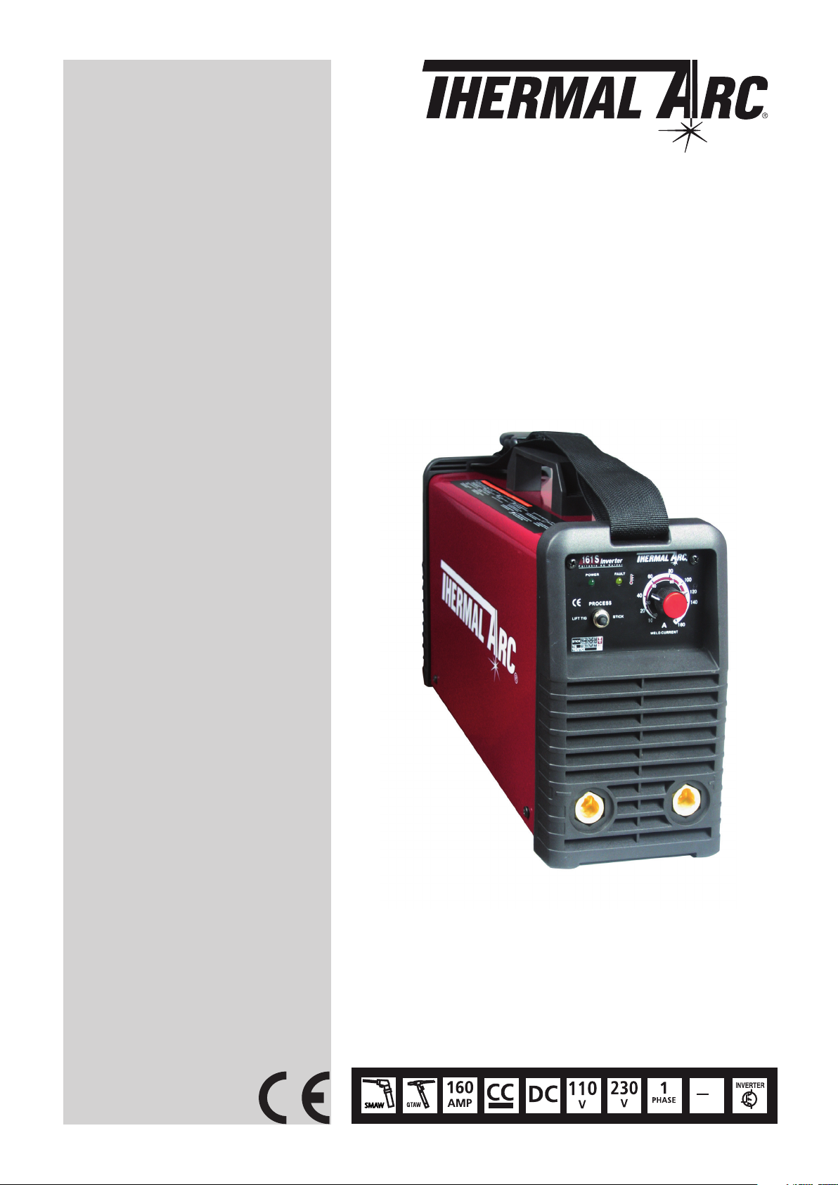
161 S
®
THERMAL ARC
INVERTER ARC WELDER
Operating Manual
Revision: AB Issue Date: July 14, 2011 Manual No.: 0-5183
Operating Features:

WE APPRECIATE YOUR BUSINESS!
Congratulations on your new Thermal Arc product. We are proud
to have you as our customer and will strive to provide you with
the best service and reliability in the industry. This product
is backed by our extensive warranty and world-wide service
network. To locate your nearest distributor or service agency call
+44 (0) 1257 261 755, or visit us on the web at www.Thermalarc.
com.
This Operating Manual has been designed to instruct you on the
correct use and operation of your Thermal Arc product. Your
satisfaction with this product and its safe operation is our ultimate
concern. Therefore please take the time to read the entire manual,
especially the Safety Precautions. They will help you to avoid potential
hazards that may exist when working with this product.
YOU ARE IN GOOD COMPANY!
The Brand of Choice for Contractors and Fabricators Worldwide.
Thermal Arc is a Global Brand of Arc Welding Products for Thermadyne
Industries Inc. We manufacture and supply to major welding industry
sectors worldwide including; Manufacturing, Construction, Mining,
Automotive, Aerospace, Engineering, Rural and DIY/Hobbyist.
We distinguish ourselves from our competition through marketleading, dependable products that have stood the test of time. We
pride ourselves on technical innovation, competitive prices, excellent
delivery, superior customer service and technical support, together
with excellence in sales and marketing expertise.
Above all, we are committed to develop technologically advanced
products to achieve a safer working environment within the welding
industry.

!
WARNINGS
Read and understand this entire Manual and your employer’s safety practices before installing,
operating, or servicing the equipment.
While the information contained in this Manual represents the Manufacturer’s best judgment, the
Manufacturer assumes no liability for its use.
Operating Manual Number 0-5183 for:
Thermal Arc 161 S Power Source Arc Welder Part No. W1003604
Thermal Arc 161 S System with Stick Kit & Case Part No. W1003605
Published by:
Thermadyne Europe
Europa Building
Chorley Industrial Park
Chorley, Lancaster,
England, PR6 7BX
www.thermalarc.com
Copyright
Thermadyne Industries Inc.
®
All rights reserved.
Reproduction of this work, in whole or in part, without written permission of the publisher is prohibited.
The publisher does not assume and hereby disclaims any liability to any party for any loss or damage
caused by any error or omission in this Manual, whether such error results from negligence, accident, or
any other cause.
Publication Date: January 30, 2011
Revision AB Date: July 14, 2011
Record the following information for Warranty purposes:
Where Purchased: ____________________________________
Purchase Date: ____________________________________
©
2010 by
Equipment Serial #: ____________________________________
i

TABLE OF CONTENTS
SECTION 1:SAFETY INSTRUCTIONS AND WARNINGS ................................................ 1-1
1.01 Arc Welding Hazards ....................................................................................... 1-1
1.02 General Safety Information for Victor CS Regulator .......................................... 1-4
1.03 Principal Safety Standards ....................................................................................
1.04 Symbol Chart .................................................................................................. 1-6
1.05 Declaration Of Conformity .............................................................................. 1-7
SECTION 2:INTRODUCTION ............................................................................... 2-1
2.01 How to Use This Manual ................................................................................. 2-1
2.02 Equipment Identification ................................................................................. 2-1
2.03 Receipt of Equipment ...................................................................................... 2-1
2.04 Description ..................................................................................................... 2-1
2.05 Transportation Methods .................................................................................. 2-1
2.06 Duty Cycle ....................................................................................................... 2-1
2.07 Specifications ................................................................................................. 2-2
SECTION 3:INSTALLATION ................................................................................ 3-1
3.01 Environment ................................................................................................... 3-1
3.02 Location .......................................................................................................... 3-1
3.03 Electrical Input Connections ........................................................................... 3-1
3.04 Electromagnetic Compatibility ........................................................................ 3-3
3.05 Setup for Welding ........................................................................................... 3-4
3.06 STICK (MMA) Setup ....................................................................................... 3-5
3.07 LIFT TIG (GTAW) Setup................................................................................... 3-6

TABLE OF CONTENTS
SECTION 4:OPERATION .................................................................................... 4-1
4.01 Front Panel ..................................................................................................... 4-1
4.02 Welding Current Control Explanation .............................................................. 4-2
4.03 STICK (MMA) Electrode Polarity ..................................................................... 4-2
4.04 Effects of Stick Welding Various Materials ...................................................... 4-3
4.05 GTAW Electrode Polarity ................................................................................. 4-4
4.06 Guide for Selecting Filler Wire ........................................................................ 4-4
4.07 Tungsten Electrode Current Ranges ................................................................ 4-4
4.08 Shielding Gas Selection .................................................................................. 4-4
4.09 Tungsten Electrode Types ............................................................................... 4-4
4.10 TIG Welding Parameters for Steel ................................................................... 4-5
4.11 Arc Welding Practice ....................................................................................... 4-5
4.12 Welding Position ............................................................................................. 4-6
4.13 Joint Preparations ........................................................................................... 4-7
4.14 Arc Welding Technique ................................................................................... 4-8
4.15 The Welder ...................................................................................................... 4-8
4.16 Striking the Arc ............................................................................................... 4-8
4.17 Arc Length ...................................................................................................... 4-8
4.18 Rate of Travel .................................................................................................. 4-8
4.19 Making Welded Joints ..................................................................................... 4-9
4.20 Distortion ...................................................................................................... 4-11
4.21 The Cause of Distortion ................................................................................ 4-11
4.22 Overcoming Distortion Effects ...................................................................... 4-12
SECTION 5:SERVICE ....................................................................................... 5-1
5.01 Maintenance and Inspection ........................................................................... 5-1
5.02 STICK (MMA) Welding Problems ................................................................... 5-2
5.03 TIG Welding Problems ................................................................................... 5-3
5.04 Power Source Problems ................................................................................ 5-4
APPENDIX 1: OPTIONS AND ACCESSORIES ............................................................ A-1
APPENDIX 2: REPLACEMENT PARTS .................................................................... A-2
APPENDIX 3: SYSTEM SCHEMATIC ..................................................................... A-4
LIMITED WARRANTY & WARRANTY SCHEDULE

Thermal Arc 161S Stick System
Part Number W1003605
• ThermalArc161Spowersupplyintoolbox
• Electrodeholder,5m(16.4ft)
• Worklead,5m(16.4ft)
• 4GP3.2mm(1/8")diastickelectrodes
• Operatingmanual
Art# A-09913
SAFETY INSTRUCTIONS THERMAL ARC 161 S
!
SECTION 1:
SAFETY INSTRUCTIONS AND WARNINGS
WARNING
PROTECT YOURSELF AND OTHERS FROM POSSIBLE SERIOUS INJURY OR DEATH. KEEP CHILDREN AWAY. PACEMAKER WEARERS
KEEP AWAY UNTIL CONSULTING YOUR DOCTOR. DO NOT LOSE THESE INSTRUCTIONS. READ OPERATING/INSTRUCTION MANUAL
BEFORE INSTALLING, OPERATING OR SERVICING THIS EQUIPMENT.
Welding products and welding processes can cause serious injury or death, or damage to other equipment or property, if the operator does
not strictly observe all safety rules and take precautionary actions.
Safe practices have developed from past experience in the use of welding and cutting. These practices must be learned through study and
training before using this equipment. Some of these practices apply to equipment connected to power lines; other practices apply to engine
driven equipment. Anyone not having extensive training in welding and cutting practices should not attempt to weld.
Safe practices are outlined in the American National Standard Z49.1 entitled: SAFETY IN WELDING AND CUTTING. This publication and other
guides to what you should learn before operating this equipment are listed at the end of these safety precautions. HAVE ALL INSTALLATION,
OPERATION, MAINTENANCE, AND REPAIR WORK PERFORMED ONLY BY QUALIFIED PEOPLE.
1.01 Arc Welding Hazards
8. Do not use worn, damaged, undersized, or poorly spliced
cables.
9. Do not wrap cables around your body.
WARNING
ELECTRIC SHOCK can kill.
Touching live electrical parts can cause fatal shocks
or severe burns. The electrode and work circuit is
electrically live whenever the output is on. The input
power circuit and machine internal circuits are also
live when power is on. In semi-automatic or automatic
wire welding, the wire, wire reel, drive roll housing, and
all metal parts touching the welding wire are electrically live. Incorrectly installed or improperly grounded
equipment is a hazard.
1. Do not touch live electrical parts.
2. Wear dry, hole-free insulating gloves and body protection.
3. Insulate yourself from work and ground using dry insulating
mats or covers.
4. Disconnect input power or stop engine before installing or
servicing this equipment. Lock input power disconnect switch
open, or remove line fuses so power cannot be turned on
accidentally.
5. Properly install and ground this equipment according to its
Owner’s Manual and national, state, and local codes.
6. Turn off all equipment when not in use. Disconnect power to
equipment if it will be left unattended or out of service.
7. Use fully insulated electrode holders. Never dip holder in water
to cool it or lay it down on the ground or the work surface. Do
not touch holders connected to two welding machines at the
same time or touch other people with the holder or electrode.
10. Ground the workpiece to a good electrical (earth) ground.
11. Do not touch electrode while in contact with the work (ground)
circuit.
12. Use only well-maintained equipment. Repair or replace damaged
parts at once.
13. In confined spaces or damp locations, do not use a welder with
AC output unless it is equipped with a voltage reducer. Use
equipment with DC output.
14. Wear a safety harness to prevent falling if working above floor
level.
15. Keep all panels and covers securely in place.
WARNING
ARC RAYS can burn eyes and skin; NOISE can damage
hearing. Arc rays from the welding process produce
intense heat and strong ultraviolet rays that can
burn eyes and skin. Noise from some processes can
damage hearing.
1. Wear a welding helmet fitted with a proper shade of filter (see
ANSI Z49.1 listed in Safety Standards) to protect your face and
eyes when welding or watching.
2. Wear approved safety glasses. Side shields recommended.
3. Use protective screens or barriers to protect others from flash
and glare; warn others not to watch the arc.
4. Wear protective clothing made from durable, flame-resistant
material (wool and leather) and foot protection.
5. Use approved ear plugs or ear muffs if noise level is high.
Manual 0-5183 1-1 Safety Instructions

THERMAL ARC 161 S SAFETY INSTRUCTIONS
g
g
WARNING
FUMES AND GASES can be hazardous to your
health.
Welding produces fumes and gases. Breathing these
fumes and gases can be hazardous to your health.
1. Keep your head out of the fumes. Do not breathe the fumes.
2. If inside, ventilate the area and/or use exhaust at the arc to
remove welding fumes and gases.
3. If ventilation is poor, use an approved air-supplied respirator.
4. Read the Material Safety Data Sheets (MSDSs) and the
manufacturer’s instruction for metals, consumables, coatings,
and cleaners.
5. Work in a confined space only if it is well ventilated, or while
wearing an air-supplied respirator. Shielding gases used for
welding can displace air causing injury or death. Be sure the
breathing air is safe.
6. Do not weld in locations near degreasing, cleaning, or spraying
operations. The heat and rays of the arc can react with vapours
to form highly toxic and irritating gases.
7. Do not weld on coated metals, such as galvanized, lead, or
cadmium plated steel, unless the coating is removed from the
weld area, the area is well ventilated, and if necessary, while
wearing an air-supplied respirator. The coatings and any metals
containing these elements can give off toxic fumes if welded.
WARNING
WELDING can cause fire or explosion.
Sparks and spatter fly off from the welding arc.
The flying sparks and hot metal, weld spatter, hot
workpiece, and hot equipment can cause fires and
burns. Accidental contact of electrode or welding
wire to metal objects can cause sparks, overheating,
or fire.
1. Protect yourself and others from flying sparks and hot metal.
2. Do not weld where flying sparks can strike flammable
material.
3. Remove all flammables within 10.7 m (35 ft) of the welding
arc. If this is not possible, tightly cover them with approved
covers.
4. Be alert that welding sparks and hot materials from welding
can easily go through small cracks and openings to adjacent
areas.
5. Watch for fire, and keep a fire extinguisher nearby.
6. Be aware that welding on a ceiling, floor, bulkhead, or partition
can cause fire on the hidden side.
7. Do not weld on closed containers such as tanks or drums.
8. Connect work cable to the work as close to the welding area
as practical to prevent welding current from travelling long,
Eye protection filter shade selector for welding or cutting
(goggles or helmet), from AWS A6.2-73.
Welding or Cutting
Operation
Torch soldering 2
Torch brazing 3 or 4 Non-ferrous base metal All 11
Oxygen Cutting
Light Under 1 in., 25 mm 3 or 4 Gas tungsten arc welding All 12
Medium 1 to 6 in., 25-150 mm 4 or 5 (TIG) All 12
Heavy Over 6 in., 150 mm 5 or 6 Atomic hydrogen welding All 12
Gas welding
Light Under 1/8 in., 3 mm 4 or 5 Plasma arc welding
Medium 1/8 to 1/2 in., 3-12 mm 5 or 6
Heavy Over 1/2 in., 12 mm 6 or 8 Light 12
Shielded metal-arc
welding
(stick) electrodes
Electrode Size
Metal Thickness
or Weldin
Under 5/32 in., 4 mm 10 Heavy 14
5/32 to 1/4 in.,
Over 1/4 in., 6.4 mm 14 Light Under 300 Amp 9
Current
4 to 6.4 mm
Filter
Shade
No.
12
Welding or Cutting
Operation
Gas metal-arc
welding (MIG)
Non-ferrous base metal All 12
Carbon arc welding All 12
Carbon arc air gouging
Plasma arc cutting
Medium 300 to 400 Amp 12
Heavy Over 400 Amp 14
Electrode Size
Metal Thickness
or Weldin
Filter
Shade
No.
Safety Instructions 1-2 Manual 0-5183
SAFETY INSTRUCTIONS THERMAL ARC 161 S
!
possibly unknown paths and causing electric shock and fire
hazards.
9. Do not use welder to thaw frozen pipes.
10. Remove stick electrode from holder or cut off welding wire at
contact tip when not in use.
WARNING
FLYING SPARKS AND HOT METAL can cause injury.
Chipping and grinding cause flying metal. As welds
cool, they can throw off slag.
1. Wear approved face shield or safety goggles. Side shields
recommended.
2. Wear proper body protection to protect skin.
WARNING
CYLINDERS can explode if damaged.
Shielding gas cylinders contain gas under high
pressure. If damaged, a cylinder can explode. Since
gas cylinders are normally part of the welding process,
be sure to treat them carefully.
1. Protect compressed gas cylinders from excessive heat,
mechanical shocks, and arcs.
WARNING
ENGINE EXHAUST GASES can kill.
Engines produce harmful exhaust gases.
1. Use equipment outside in open, well-ventilated areas.
2. If used in a closed area, vent engine exhaust outside and away
from any building air intakes.
WARNING
ENGINE FUEL can cause fire or explosion.
Engine fuel is highly flammable.
1. Stop engine before checking or adding fuel.
2. Do not add fuel while smoking or if unit is near any sparks or
open flames.
3. Allow engine to cool before fuelling. If possible, check and add
fuel to cold engine before beginning job.
4. Do not overfill tank — allow room for fuel to expand.
5. Do not spill fuel. If fuel is spilled, clean up before starting
engine.
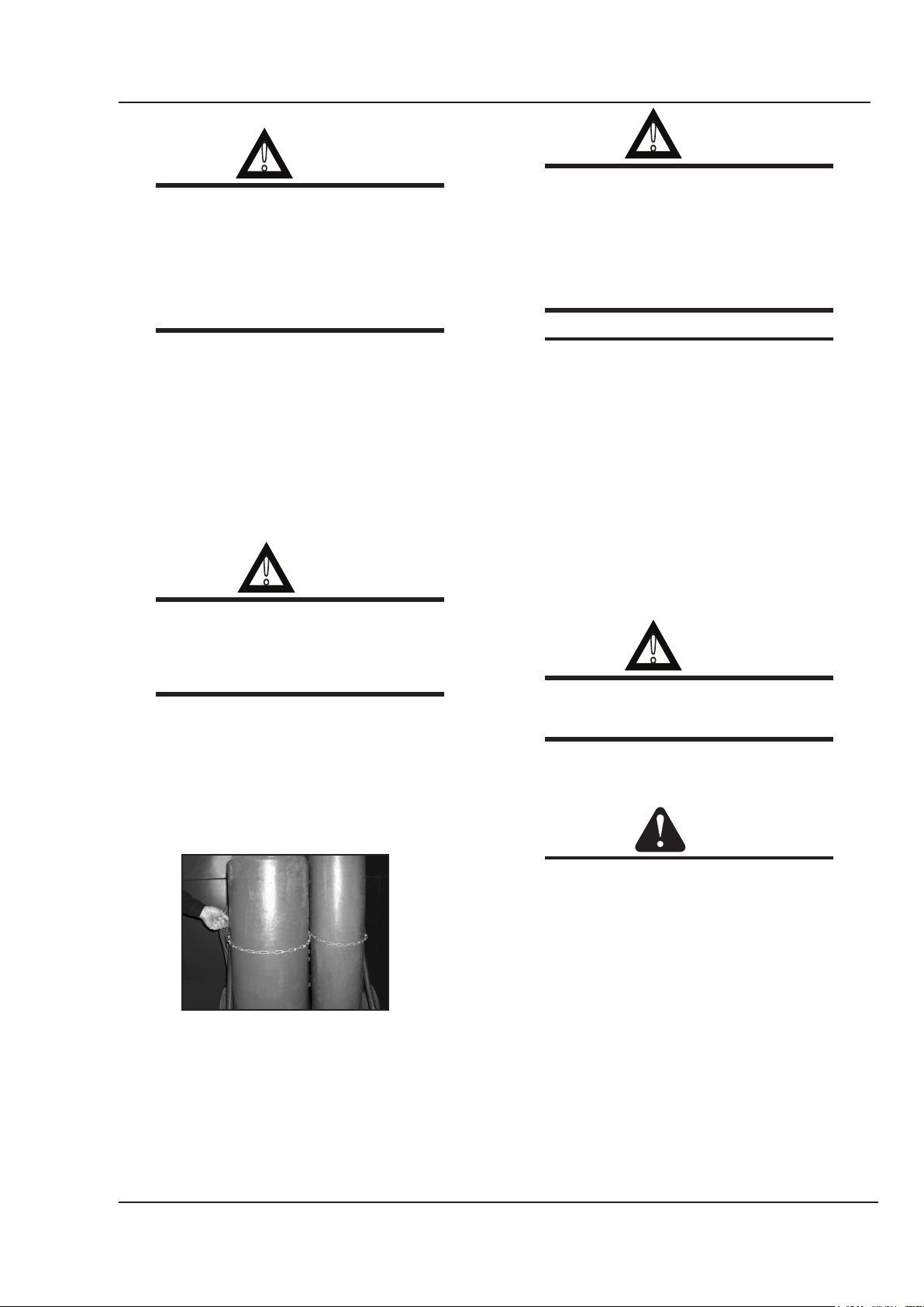
2. Install and secure cylinders in an upright position by chaining
them to a stationary support or equipment cylinder rack to
prevent falling or tipping.
3. Keep cylinders away from any welding or other electrical
circuits.
4. Never allow a welding electrode to touch any cylinder.
5. Use only correct shielding gas cylinders, regulators, hoses, and
fittings designed for the specific application; maintain them and
associated parts in good condition.
6. Turn face away from valve outlet when opening cylinder
valve.
7. Keep protective cap in place over valve except when cylinder is
in use or connected for use.
8. Read and follow instructions on compressed gas cylinders,
associated equipment, and CGA publication P-1 listed in Safety
Standards.
WARNING
Engines can be dangerous.
WARNING
MOVING PARTS can cause injury.
Moving parts, such as fans, rotors, and belts can cut fingers and
hands and catch loose clothing.
1. Keep all doors, panels, covers, and guards closed and
securely in place.
2. Stop engine before installing or connecting unit.
3. Have only qualified people remove guards or covers for
maintenance and troubleshooting as necessary.
4. To prevent accidental starting during servicing, disconnect
negative (-) battery cable from battery.
5. Keep hands, hair, loose clothing, and tools away from
moving parts.
6. Reinstall panels or guards and close doors when servicing
is finished and before starting engine.
WARNING
SPARKS can cause BATTERY GASES TO EXPLODE;
BATTERY ACID can burn eyes and skin.
Manual 0-5183 1-3 Safety Instructions
THERMAL ARC 161 S SAFETY INSTRUCTIONS
!
!
!
Batteries contain acid and generate explosive gases.
1. Always wear a face shield when working on a battery.
2. Stop engine before disconnecting or connecting battery
cables.
3. Do not allow tools to cause sparks when working on a
battery.
4. Do not use welder to charge batteries or jump start vehicles.
5. Observe correct polarity (+ and –) on batteries.
WARNING
STEAM AND PRESSURIZED HOT COOLANT can burn
face, eyes, and skin.
The coolant in the radiator can be very hot and under
pressure.
1. Do not remove radiator cap when engine is hot. Allow engine
to cool.
2. Wear gloves and put a rag over cap area when removing cap.
3. Allow pressure to escape before completely removing cap.
Considerations About Welding And The Effects of Low
Frequency Electric and Magnetic Fields
The following is a quotation from the General Conclusions Section
of the U.S. Congress, Office of Technology Assessment, Biological
Effects of Power Frequency Electric & Magnetic Fields - Background
Paper, OTA-BP-E-63 (Washington, DC: U.S. Government Printing
Office, May 1989): “...there is now a very large volume of scientific
findings based on experiments at the cellular level and from studies
with animals and people which clearly establish that low frequency
magnetic fields interact with, and produce changes in, biological
systems. While most of this work is of very high quality, the results
are complex. Current scientific understanding does not yet allow
us to interpret the evidence in a single coherent framework. Even
more frustrating, it does not yet allow us to draw definite conclusions about questions of possible risk or to offer clear science-based
advice on strategies to minimize or avoid potential risks.”
To reduce magnetic fields in the workplace, use the following
procedures.
1. Keep cables close together by twisting or taping them.
2. Arrange cables to one side and away from the operator.
3. Do not coil or drape cable around the body.
4. Keep welding power source and cables as far away from
body as practical.
NOTE
ABOUT PACEMAKERS:
The above procedures are among those also normally
recommended for pacemaker wearers. Consult your
doctor for complete information.
1.02 General Safety Information for
Victor CS Regulator
A Fire Prevention
Welding and cutting operations use fire or combustion as a basic
tool. The process is very useful when properly controlled. However,
it can be extremely destructive if not performed cor rectly in the
proper environment.
1. The work area must have a fireproof floor.
2. Work benches or tables used during welding or cutting
operations must have fireproof tops.
3. Use heat resistant shields or other approved material to
protect nearby walls or unprotected flooring from sparks and
hot metal.
4. Keep an approved fire extinguisher of the proper size and
type in the work area. Inspect it regularly to ensure that
it is in proper working order. Know how to use the fire
extin guisher.
5. Move combustible materials away from the work site. If you
can not move them, protect them with fireproof covers.
WARNING
NEVER perform welding, heating, or cutting operations
on a container that has held toxic, combustible
or flammable liq uids, or vapours. NEVER perform
welding, heating, or cutting operations in an area
containing combustible vapours, flam mable liquids,
or explosive dust.
B Housekeeping
WARNING
NEVER allow oxygen to contact grease, oil, or other
flam mable substances. Although oxygen by itself will
not burn, these substances become highly explosive.
They can ignite and burn violently in the presence of
oxygen.
Keep ALL apparatus clean and free of grease, oil and other flammable substances.
Safety Instructions 1-4 Manual 0-5183
SAFETY INSTRUCTIONS THERMAL ARC 161 S
!
!
!
!
C Ventilation
WARNING
WARNING
Ade quately ventilate welding, heating, and cutting
work areas to prevent accumulation of explosive or
toxic concen trations of gases. Certain combinations
of metals, coatings, and gases generate toxic fumes.
Use respiratory protection equipment in these circumstances. When welding/brazing, read and understand
the Material Safety Data Sheet for the welding/brazing
alloy.
D Personal Protection
Gas flames produce infrared radiation which may have a harm ful
effect on the skin and especially on the eyes. Select goggles or a
mask with tempered lenses, shaded 4 or darker, to protect your eyes
from injury and provide good visibility of the work.
Always wear protective gloves and flame-resistant clothing to protect
skin and clothing from sparks and slag. Keep collars, sleeves, and
pockets buttoned. DO NOT roll up sleeves or cuff pants.
When working in a non-welding or cutting environment, always wear
suitable eye protection or face shield.
Cylinders are highly pressurized. Handle with care.
Serious accidents can result from improper handling
or mis use of compressed gas cylinders DO NOT drop
the cylinder, knock it over, or expose it to excessive
heat, flames or sparks. DO NOT strike it against other
cylinders. Contact your gas supplier or refer to CGA
P-1 “Safe Handling of Compressed Gases in Containers” publication.
NOTE
CGA P-1 publication is available by writing the Compressed Gas Association, 4221 Walney Road, 5th
Floor, Chantilly,VA 20151-2923
2. Place the valve protection cap on the cylinder whenever
mov ing it, placing it in storage, or not using it. Never drag
or roll cylinders in any way. Use a suitable hand truck to
move cylin ders.
3. Store empty cylinders away from full cylinders. Mark them
“EMPTY” and close the cylinder valve.
4. NEVER use compressed gas cylinders without a pressure
reducing regulator attached to the cylinder valve.
WARNING
Practice the following safety and operation precautions
EVERY TIME you use pressure regulation equipment.
Deviation from the following safety and operation
instructions can result in fire, explosion, damage to
equipment, or injury to the operator.
E Compressed Gas Cylinders
The Department of Transportation (DOT) approves the design and
manufacture of cylinders that contain gases used for welding or
cutting operations.
1. Place the cylinder (Figure 1-1) where you will use it. Keep
the cylinder in a vertical position. Secure it to a cart, wall, work
bench, post, etc.
Figure 1-1: Gas Cylinders
5. Inspect the cylinder valve for oil, grease, and damaged
parts.
WARNING
DO NOT use the cylinder if you find oil, grease or damaged parts. Inform your gas supplier of this condition
immediately.
6. Momentarily open and close (called “cracking”) the cylinder
valve to dislodge any dust or dirt that may be present in the
valve.
CAUTION
Open the cylinder valve slightly. If you open the valve
too much, the cylinder could tip over. When cracking
the cylinder valve, DO NOT stand directly in front of
the cylinder valve. Always perform cracking in a well
ventilated area. If an acetylene cylinder sprays a mist
when cracked, let it stand for 15 minutes. Then, try to
crack the cylinder valve again. If this problem persists,
contact your gas supplier.
Manual 0-5183 1-5 Safety Instructions
THERMAL ARC 161 S SAFETY INSTRUCTIONS
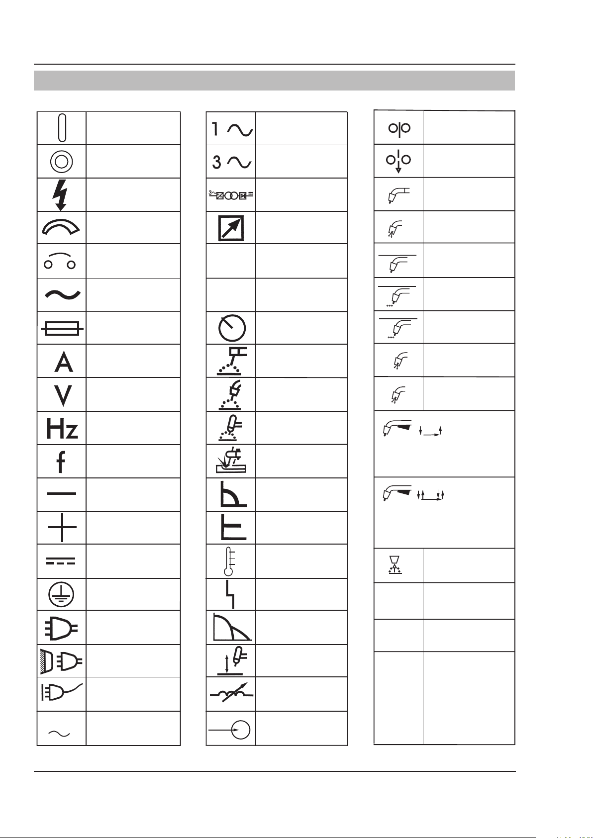
1.04 Symbol Chart
Note that only some of these symbols will appear on your model.
On
Off
Dangerous Voltage
Increase/Decrease
Circuit Breaker
AC Auxiliary Power
Fuse
Amperage
Voltage
X
%
Single Phase
Three Phase
Three Phase Static
Frequency ConverterTransformer-Rectifier
Remote
Duty Cycle
Percentage
Panel/Local
Shielded Metal
Arc Welding (MMA)
Gas Metal Arc
Welding (GMAW)
Wire Feed Function
Wire Feed Towards
Workpiece With
Output Voltage Off.
Welding Gun
Purging Of Gas
Continuous Weld
Mode
Spot Weld Mode
Spot Time
t
t2
Preflow Time
Postflow Time
t1
Hertz (cycles/sec)
Frequency
Negative
Positive
Direct Current (DC)
Protective Earth
(Ground)
Line
Line Connection
Auxiliary Power
Gas Tungsten Arc
Welding (GTAW)
Air Carbon Arc
Cutting (CAC-A)
Constant Current
Constant Voltage
Or Constant Potential
High Temperature
Fault Indication
Arc Force
Touch Start (GTAW)
Variable Inductance
2 Step Trigger
Operation
Press to initiate wirefeed and
welding, release to stop.
4 Step Trigger
Operation
Press and hold for preflow, release
to start arc. Press to stop arc, and
hold for preflow.
Burnback Time
t
IPM
MPM
Inches Per Minute
Meters Per Minute
115V 15A
Safety Instructions 1-6 Manual 0-5183
Receptacle RatingAuxiliary Power
Voltage Input
V
Art # A-09917

SAFETY INSTRUCTIONS THERMAL ARC 161 S
1.05 Declaration Of Conformity
Manufacturer: Thermadyne Corporation
Address: 82 Benning Street
West Lebanon, New Hampshire 03784
USA
The equipment described in this manual conforms to all applicable aspects and regulations of the ‘Low Voltage Directive’ (European
Council Directive 73/23/EEC as amended by Council Directive 93/68/EEC) and to the National legislation for the enforcement of this
Directive.
The equipment described in this manual conforms to all applicable aspects and regulations of the “EMC Directive” (European Council
Directive 89/336/EEC) and to the National legislation for the enforcement of this Directive.
Serial numbers are unique with each individual piece of equipment and details description, parts used to manufacture a unit and date of
manufacture.
National Standard and Technical Specifications
The product is designed and manufactured to a number of standards and technical requirements. Among them are:
• CENELECEN50199EMCProductStandardforArcWeldingEquipment.
• ISO/IEC60974-1(BS638-PT10)(EN60974-1)(EN50192)(EN50078)applicabletoweldingequipmentandassociated
accessories.
• Forenvironmentswithincreasedhazardofelectricalshock,PowerSuppliesbearingtheSmarkconformtoEN50192whenused
in conjunction with hand torches with exposed cutting tips, if equipped with properly installed standoff guides.
• Extensiveproductdesignverificationisconductedatthemanufacturingfacilityaspartoftheroutinedesignandmanufacturing
process. This is to ensure the product is safe, when used according to instructions in this manual and related industry standards,
and performs as specified. Rigorous testing is incorporated into the manufacturing process to ensure the manufactured product
meets or exceeds all design specifications.
Thermadyne has been manufacturing products for more than 30 years, and will continue to achieve excellence in our area of
manufacture.
Manufacturers responsible representative:
Steve Ward
Operations Director
Thermadyne Europe
Europa Building
Chorley N Industrial Park
Chorley, Lancashire,
England PR6 7BX
Manual 0-5183 1-7 Safety Instructions

THERMAL ARC 161 S SAFETY INSTRUCTIONS
This page left blank intentionally.
Safety Instructions 1-8 Manual 0-5183

INTRODUCTION THERMAL ARC 161 S
!
!
SECTION 2:
INTRODUCTION
2.01 How to Use This Manual
This Operating Manual usually applies to the part numbers listed on page i. If none are underlined, they are
all covered by this manual. To ensure safe operation,
read the entire manual, including the chapter on safety
instructions and warnings. Throughout this manual, the
word WARNING, CAUTION and NOTE may appear. Pay
particular attention to the information provided under
these headings. These special annotations are easily
recognized as follows:
WARNING
Gives information regarding possible personal injury. Warnings will be enclosed in a
box such as this.
CAUTION
Refers to possible equipment damage. Cautions will be shown in bold type.
NOTE
Offers helpful information concerning certain
operating procedures. Notes will be shown
in italics
2.02 Equipment Identification
The unit’s identification number (specification or part
number), model, and serial number usually appear
on a nameplate attached to the machine. Equipment
which does not have a nameplate attached to the
machine is identified only by the specification or part
number printed on the shipping container. Record these
numbers for future reference.
2.03 Receipt of Equipment
When you receive the equipment, check it against the
invoice to make sure it is complete and inspect the
equipment for possible damage due to shipping. If there
is any damage, notify the carrier immediately to file a
claim. Furnish complete information concerning damage
claims or shipping errors to the location in your area
listed in the inside back cover of this manual. Include
all equipment identification numbers as described above
along with a full description of the parts in error.
2.04 Description
This compact inverter welding machine has infinitely
adjustable welding current from 10 to 160 amps. It uses
standard general purpose STICK (MMA) 2.5mm (3/32”)
electrodes for light gauge work, generally less than
1/8” (3.2mm) thick and STICK (MMA) 1/8” (3.2mm)
electrodes for heavier material. The unit also has a
LIFT TIG (GTAW) welding mode that offers stable TIG
welding characteristics when used with a suitable TIG
torch and shielding gas.
2.05 Transportation Methods
WARNING
ELECTRIC SHOCK can kill. DO NOT TOUCH
live electric parts. Disconnect input power
conductors from de-energized supply line
before moving the welding power source.
WARNING
FALLING EQUIPMENT can cause serious
personal injury and equipment damage.
Lift unit with handle on top of case. Use handcart or
similar device of adequate capacity. If using a fork
lift vehicle, place secure unit on a proper skid before
transporting.
2.06 Duty Cycle
The rated duty cycle of a Welding Power Source, is
the percentage of a ten minute time period that it
may be operated at its rated output current without
exceeding the temperature limits of the insulation of the
component parts. To explain the 10 minute duty cycle
period, suppose a Welding Power Source is designed to
operate with a 35% duty cycle at 160 amperes and 26.4
volts. This means that it has been designed and built
to provide the rated amperage (160A) for 3.5 minutes,
i.e. arc welding time, out of every 10 minute period
(35% of 10 minutes is 3.5 minutes). During the other
6.5 minutes of the 10 minute period the Welding Power
Source must idle and be allowed to cool.
Manual 0-5183 2-1 Introduction
 Loading...