

Page 1

®
MERLIN
™
PAK® 15XC
Plasma Cutting System
October 6, 1999
Instruction Manual
Manual No. 0-2251
Page 2
WARNING
Read and understand this entire Instruction Manual and your
employer’s safety practices before installing, operating, or
servicing the equipment.
WARNING
While the information contained in this Instruction Manual
represents our best judgement, Thermal Dynamics Corporation
assumes no liability for its use.
Merlin PAK 15XC Plasma Cutting System
With PCH/M-150 Torch
Instruction Manual Number 0-2251
Published by:
Thermal Dynamics Corporation
Industrial Park No. 2
West Lebanon, New Hampshire, USA 03784
(603) 298-5711
Copyright 1990 by
Thermal Dynamics Corporation
All rights reserved.
Reproduction of this work, in whole or in part, without written
permission of the publisher is prohibited.
The publisher does not assume and hereby disclaims any liability
to any party for any loss or damage caused by any error or
omission in the Merlin PAK 15XC Plasma Cutting System With
PCH/M-150 Torch Instruction Manual, whether such error
results from negligence, accident, or any other cause.
Printed in the United States of America
October 6, 1999
Page 3

TABLE OF CONTENTS
SECTION 1:
GENERAL INFORMATION .................................................................................................. 1
1.01 Notes, Cautions and Warnings ...................................................................... 1
1.02 Important Safety Precautions ........................................................................ 1
1.03 Publications ................................................................................................... 2
1.04 Note, Attention et A v ertissement ................................................................... 3
1.05 Precautions De Securite Importantes ............................................................ 3
1.06 Documents De Reference ............................................................................. 5
1.07 Declaration of Conformity .............................................................................. 7
1.08 Statement of W arr anty................................................................................... 8
SECTION 2: INTR ODUCTION & DESCRIPTION........................................................................ 9
2.1 SYSTEM DESCRIPTION ................................................................................ 9
2.2 POWER SUPPLY SPECIFICATIONS ............................................................ 10
2.3 TORCH SPECIFICATIONS............................................................................ 11
2.4 OPTIONS AND ACCESSORIES ................................................................... 13
2.5 THEORY OF OPERATION ............................................................................ 14
SECTION 3: INSTALLATION PROCEDURES ........................................................................... 17
3.1 UNPACKING THE SYSTEM .......................................................................... 17
3.2 LOCATION .................................................................................................... 18
3.3 PLASMA AND SECONDARY CONNECTIONS............................................. 18
3.4 ELECTRICAL CONNECTIONS ..................................................................... 22
3.5 W ORK AND GR OUND CONNECTIONS....................................................... 24
3.6 COOLANT INSTALLATION............................................................................ 25
3.7 AUXILIARY CONNECTIONS......................................................................... 26
3.8 LIFTING THE PO WER SUPPLY.................................................................... 28
SECTION 4: OPERATION ......................................................................................................... 29
4.1 OPERATING CONTROLS ............................................................................. 29
4.2 PRE-OPERATION SET -UP............................................................................ 32
4.3 TORCH PARTS SELECTION ........................................................................ 33
4.4 GAS SELECTION FOR PLASMA CUTTING................................................. 36
4.5 PLASMA CUTTING OPERATION ................................................................. 40
4.6 HAND TORCH OPERATION ......................................................................... 44
4.7 MACHINE TORCH OPERATION ................................................................... 46
4.8 PIERCING ..................................................................................................... 49
4.9 GOUGING OPERATION ............................................................................... 50
4.10 COMMON OPERATING ERRORS .............................................................. 53
4.11 CUTTING SPEEDS ..................................................................................... 54
4.12 SEQUENCE OF OPERATION ..................................................................... 61
Page 4

TABLE OF CONTENTS (continued)
SECTION 5: CUST OMER/OPERATOR SERVICE..................................................................... 63
5.1 TORCH MAINTENANCE ............................................................................... 63
5.2 HAND TORCH HEAD REPLACEMENT ........................................................ 64
5.3 MACHINE TORCH HEAD REPLACEMENT .................................................. 66
5.4 HAND TORCH SWITCH REPLACEMENT .................................................... 68
5.5 HAND TORCH LEADS REPLACEMENT....................................................... 69
5.6 MACHINE TORCH LEADS REPLACEMENT ................................................ 71
5.7 LEADS EXTENSION KITS - HAND TORCH.................................................. 73
5.8 LEADS EXTENSION KITS - MACHINE TORCH ........................................... 75
5.9 POWER SUPPLY MAINTENANCE................................................................ 78
5.10 TROUBLESHOOTING THEORY ................................................................. 79
5.11 TROUBLESHOOTING GUIDE ..................................................................... 83
5.12 SERVICE AND TEST PROCEDURES ........................................................ 89
SECTION 6: PARTS LISTS........................................................................................................ 99
6.1 ABOUT THE PARTS LIST ............................................................................. 99
6.2 SYSTEM COMPONENTS AND ACCESSORIES ........................................ 100
6.3 ACCESS PANEL COMPONENTS ............................................................... 102
6.4 FRONT PANEL/CHASSIS COMPONENTS................................................. 103
6.5 REAR PANEL COMPONENTS.................................................................... 104
6.6 BASE COMPONENTS ................................................................................ 106
6.7 UPPER CHASSIS COMPONENTS............................................................. 108
6.8 MAIN HEATSINK COMPONENTS .............................................................. 110
6.9 TORCH COMPONENTS ............................................................................. 112
6.10 TORCH ACCESSORIES ........................................................................... 114
APPENDIX I: LADDER DIAGRAM - 120 VAC.......................................................................... 115
APPENDIX II: LADDER DIA GRAM - 15 VDC .......................................................................... 116
APPENDIX III: DIGITAL CURRENT CONTROL INTERF ACE.................................................. 117
APPENDIX IV: CNC INTERFACE ............................................................................................ 118
APPENDIX V: POWER SUPPLY TO REMOTE CONTROL CABLE INTERFACE .................... 119
APPENDIC VI: REMOTE CONTROL CHASSIS SCHEMATIC................................................. 120
APPENDIX VII: RECOMMENDED ROUTINE MAINTENANCE SCHEDULE
FOR WATER COOLED PLASMA CUTTING SYSTEMS .................................................. 121
APPENDIX VIII: SYSTEM SCHEMATIC .................................................................................. 122
Page 5
SECTION 1:
GENERAL INFORMATION
1.01 Notes, Cautions and Warnings
Throughout this manual, notes, cautions, and warnings
are used to highlight important information. These highlights are categorized as follows:
NOTE
An operation, procedure, or backgr ound information which requires additional emphasis or is helpful in efficient operation of the system.
CAUTION
A procedure which, if not properly followed, may
cause damage to the equipment.
W ARNING
A procedure which, if not properly followed, may
cause injury to the operator or others in the operating area.
1.02 Important Safety Precautions
WARNINGS
OPERATION AND MAINTENANCE OF
PLASMA ARC EQUIPMENT CAN BE DANGEROUS AND HAZARDOUS TO YOUR
HEALTH.
GASES AND FUMES
Gases and fumes produced during the plasma cutting
process can be dangerous and hazardous to your health.
• Keep all fumes and gases from the breathing area.
Keep your head out of the welding fume plume.
• Use an air-supplied respirator if ventilation is not
adequate to remove all fumes and gases.
• The kinds of fumes and gases from the plasma arc
depend on the kind of metal being used, coatings
on the metal, and the different processes. Y ou must
be very careful when cutting or welding any metals which may contain one or more of the following:
Antimony Chromium Mercury
Arsenic Cobalt Nickel
Barium Copper Selenium
Beryllium Lead Silver
Cadmium Manganese Vanadium
• Always read the Material Safety Data Sheets (MSDS)
that should be supplied with the material you are
using. These MSDSs will give you the information
regarding the kind and amount of fumes and gases
that may be dangerous to your health.
• For information on how to test for fumes and gases
in your workplace, refer to item 1 in Subsection
1.03, Publications in this manual.
• Use special equipment, such as water or down draft
cutting tables, to capture fumes and gases.
• Do not use the plasma torch in an area where combustible or explosive gases or materials are located.
• Phosgene, a toxic gas, is generated from the vapors
of chlorinated solvents and cleansers. Remove all
sources of these vapors.
Plasma arc cutting produces intense electric and
magnetic emissions that may interfere with the
proper function of cardiac pacemakers, hearing
aids, or other electronic health equipment. Persons who work near plasma arc cutting applications should consult their medical health professional and the manufacturer of the health
equipment to determine whether a hazard exists.
To prevent possible injury, read, understand and
follow all warnings, safety precautions and instructions before using the equipment. Call 1-603298-5711 or your local distributor if you have any
questions.
Date: 6/22/99 1 GENERAL INFORMA TION
Electric Shock can injure or kill. The plasma arc process
uses and produces high voltage electrical energy. This
electric energy can cause severe or fatal shock to the operator or others in the workplace.
ELECTRIC SHOCK
• Never touch any parts that are electrically “live” or
“hot.”
• W ear dry gloves and clothing. Insulate yourself from
the work piece or other parts of the welding circuit.
• Repair or replace all worn or damaged parts.
• Extra care must be taken when the workplace is
moist or damp.
Page 6

• Install and maintain equipment according to NEC
code, refer to item 9 in Subsection 1.03, Publications.
• Disconnect power source before performing any service or repairs.
• Read and follow all the instructions in the Operating Manual.
FIRE AND EXPLOSION
Fire and explosion can be caused by hot slag, sparks, or
the plasma arc.
• Be sure there is no combustible or flammable material in the workplace. Any material that cannot be
removed must be protected.
• Ventilate all flammable or explosive vapors from
the workplace.
• Do not cut or weld on containers that may have held
combustibles.
• Provide a fire watch when working in an area wher e
fire hazards may exist.
• Hydrogen gas may be formed and trapped under
aluminum workpieces when they are cut underwater or while using a water table. DO NOT cut
aluminum alloys underwater or on a water table
unless the hydrogen gas can be eliminated or dissipated. T rapped hydr ogen gas that is ignited will
cause an explosion.
NOISE
Noise can cause permanent hearing loss. Plasma arc processes can cause noise levels to exceed safe limits. You
must protect your ears from loud noise to prevent permanent loss of hearing.
• T o pr otect your hearing fr om loud noise, wear protective ear plugs and/or ear muffs. Protect others
in the workplace.
• Noise levels should be measured to be sure the decibels (sound) do not exceed safe levels.
• For information on how to test for noise, see item 1
in Subsection 1.03, Publications, in this manual.
PLASMA ARC RAYS
Plasma Arc Rays can injure your eyes and burn your skin.
The plasma arc process produces very bright ultra violet
and infra red light. These arc rays will damage your
eyes and burn your skin if you are not properly pr otected.
• To protect your eyes, always wear a welding helmet or shield. Also always wear safety glasses with
side shields, goggles or other protective eye wear.
• Wear welding gloves and suitable clothing to protect your skin from the arc rays and sparks.
• Keep helmet and safety glasses in good condition.
Replace lenses when cracked, chipped or dirty.
• Protect others in the work area from the arc rays.
Use protective booths, screens or shields.
• Use the shade of lens as suggested in the following
per ANSI/ASC Z49.1:
Minimum Protective Suggested
Arc Current Shade No. Shade No.
Less Than 300* 8 9
300 - 400* 9 12
400 - 800* 10 14
* These values apply where the actual arc is clearly
seen. Experience has shown that lighter filters
may be used when the arc is hidden by the workpiece.
1.03 Publications
Refer to the following standards or their latest revisions
for more information:
1. OSHA, SAFETY AND HEALTH STANDARDS,
29CFR 1910, obtainable from the Superintendent of
Documents, U.S. Government Printing Office, W ashington, D.C. 20402
2. ANSI Standard Z49.1, SAFETY IN WELDING AND
CUTTING, obtainable from the American Welding
Society, 550 N.W. LeJeune Rd, Miami, FL 33126
3. NIOSH, SAFETY AND HEALTH IN ARC WELDING AND GAS WELDING AND CUTTING, obtainable from the Superintendent of Documents, U.S.
Government Printing Office, W ashington, D.C. 20402
4. ANSI Standard Z87.1, SAFE PRACTICES FOR OCCUP ATION AND EDUCA TIONAL EYE AND F ACE
PROTECTION, obtainable from American National
Standards Institute, 1430 Broadway, New York, NY
10018
5. ANSI Standard Z41.1, STANDARD FOR MEN’S
SAFETY-TOE FOOTWEAR, obtainable from the
American National Standards Institute, 1430 Broadway, New York, NY 10018
6. ANSI Standard Z49.2, FIRE PREVENTION IN THE
USE OF CUTTING AND WELDING PROCESSES,
obtainable from American National Standar ds Institute, 1430 Broadway, New York, NY 10018
7. AWS Standard A6.0, WELDING AND CUTTING
CONTAINERS WHICH HAVE HELD COMBUSTIBLES, obtainable from American Welding Society,
550 N.W. LeJeune Rd, Miami, FL 33126
GENERAL INFORMATION 2 Date 6/22/99
Page 7
8. NFPA Standard 51, OXYGEN-FUEL GAS SYSTEMS
FOR WELDING, CUTTING AND ALLIED PROCESSES, obtainable from the National Fire Protection
Association, Batterymarch Park, Quincy, MA 02269
9. NFP A Standar d 70, NA TIONAL ELECTRICAL CODE,
obtainable from the National Fire Protection Association, Batterymarch Park, Quincy, MA 02269
10. NFPA Standard 51B, CUTTING AND WELDING
PROCESSES, obtainable from the National Fire Protection Association, Batterymarch Park, Quincy, MA
02269
11. CGA Pamphlet P-1, SAFE HANDLING OF COMPRESSED GASES IN CYLINDERS, obtainable from
the Compressed Gas Association, 1235 Jefferson
Davis Highway, Suite 501, Arlington, VA 22202
12. CSA Standard W117.2, CODE FOR SAFETY IN
WELDING AND CUTTING, obtainable from the Canadian Standards Association, Standards Sales, 178
Rexdale Boulevard, Rexdale, Ontario, Canada M9W
1R3
13. NWSA booklet, WELDING SAFETY BIBLIOGRAPHY obtainable from the National Welding Supply
Association, 1900 Arch Street, Philadelphia, PA 19103
14. American W elding Society Standard A WSF4.1, RECOMMENDED SAFE PRACTICES FOR THE PREP ARA TION FOR WELDING AND CUTTING OF CONTAINERS AND PIPING THAT HAVE HELD
HAZARDOUS SUBSTANCES, obtainable from the
American Welding Society, 550 N.W. LeJeune Rd,
Miami, FL 33126
15. ANSI Standard Z88.2, PRACTICE FOR RESPIRATORY PROTECTION, obtainable from American
National Standards Institute, 1430 Broadway, New
York, NY 10018
1.04 Note, Attention et Avertissement
Dans ce manuel, les mots “note,” “attention,” et
“avertissement” sont utilisés pour mettre en relief des
informations à caractère important. Ces mises en relief
sont classifiées comme suit :
A VERTISSEMENT
Toute procédure pouvant provoquer des blessures
de l’opérateur ou des autres personnes se trouvant
dans la zone de travail en cas de non-respect de la
procédure en question.
1.05 Precautions De Securite Importantes
AVERTISSEMENTS
L’OPÉRATION ET LA MAINTENANCE DU
MATÉRIEL DE SOUDAGE À L’ARC AU JET
DE PLASMA PEUVENT PRÉSENTER DES
RISQUES ET DES DANGERS DE SANTÉ.
Coupant à l’arc au jet de plasma produit de l’énergie
électrique haute tension et des émissions
magnétique qui peuvent interférer la fonction
propre d’un “pacemaker” cardiaque, les appareils
auditif, ou autre matériel de santé electronique.
Ceux qui travail près d’une application à l’arc au
jet de plasma devrait consulter leur membre
professionel de médication et le manufacturier de
matériel de santé pour déterminer s’il existe des
risques de santé.
Il faut communiquer aux opérateurs et au personnel TOUS les dangers possibles. Afin d’éviter les
blessures possibles, lisez, comprenez et suivez tous
les avertissements, toutes les précautions de sécurité
et toutes les consignes avant d’utiliser le matériel.
Composez le + 603-298-5711 ou votr e distributeur
local si vous avez des questions.
FUMÉE et GAZ
NOTE
Toute opération, procédure ou renseignement
général sur lequel il importe d’insister davantage
ou qui contribue à l’efficacité de fonctionnement
du système.
ATTENTION
Toute procédure pouvant r ésulter
l’endommagement du matériel en cas de nonrespect de la procédur e en question.
Date: 6/22/99 3 GENERAL INFORMA TION
La fumée et les gaz produits par le procédé de jet de
plasma peuvent présenter des risques et des dangers de
santé.
• Eloignez toute fumée et gaz de votre zone de respiration. Gardez votre tête hors de la plume de fumée
provenant du chalumeau.
• Utilisez un appareil respiratoire à alimentation en
air si l’aération fournie ne permet pas d’éliminer la
fumée et les gaz.
Page 8
• Les sortes de gaz et de fumée provenant de l’arc de
plasma dépendent du genre de métal utilisé, des
revêtements se trouvant sur le métal et des différ ents
procédés. Vous devez prendre soin lorsque vous
coupez ou soudez tout métal pouvant contenir un
ou plusieurs des éléments suivants:
antimoine cadmium mercure
argent chrome nickel
arsenic cobalt plomb
baryum cuivre sélénium
béryllium manganèse vanadium
• Lisez toujours les fiches de données sur la sécurité
des matières (sigle américain “MSDS”); celles-ci
devraient être fournies avec le matériel que vous
utilisez. Les MSDS contiennent des renseignements
quant à la quantité et la nature de la fumée et des
gaz pouvant poser des dangers de santé.
• Pour des informations sur la manière de tester la
fumée et les gaz de votre lieu de travail, consultez
l’article 1 et les documents cités à la page 5.
• Utilisez un équipement spécial tel que des tables de
coupe à débit d’eau ou à courant descendant pour
capter la fumée et les gaz.
• N’utilisez pas le chalumeau au jet de plasma dans
une zone où se trouvent des matières ou des gaz
combustibles ou explosifs.
• Le phosgène, un gaz toxique, est généré par la fumée
provenant des solvants et des produits de nettoyage
chlorés. Eliminez toute source de telle fumée.
INCENDIE ET EXPLOSION
Les incendies et les explosions peuvent résulter des scories
chaudes, des étincelles ou de l’arc de plasma. Le procédé
à l’arc de plasma produit du métal, des étincelles, des
scories chaudes pouvant mettre le feu aux matières combustibles ou provoquer l’explosion de fumées
inflammables.
• Soyez certain qu’aucune matière combustible ou inflammable ne se trouve sur le lieu de travail.
Protégez toute telle matière qu’il est impossible de
retirer de la zone de travail.
• Procurez une bonne aération de toutes les fumées
inflammables ou explosives.
• Ne coupez pas et ne soudez pas les conteneurs ayant
pu renfermer des matières combustibles.
• Prévoyez une veille d’incendie lors de tout travail
dans une zone présentant des dangers d’incendie.
• Le gas hydrogène peut se former ou s’accumuler
sous les pièces de travail en aluminium lorsqu’elles
sont coupées sous l’eau ou sur une table d’eau. NE
P AS couper les alliages en aluminium sous l’eau ou
sur une table d’eau à moins que le gas hydrogène
peut s’échapper ou se dissiper. Le gas hydrogène
accumulé explosera si enflammé.
RAYONS D’ARC DE PLASMA
CHOC ELECTRIQUE
Les chocs électriques peuvent blesser ou même tuer. Le
procédé au jet de plasma requiert et produit de l’éner gie
électrique haute tension. Cette énergie électrique peut
produire des chocs graves, voire mortels, pour l’opérateur
et les autres personnes sur le lieu de travail.
• Ne touchez jamais une pièce “sous tension” ou
“vive”; portez des gants et des vêtements secs.
Isolez-vous de la pièce de travail ou des autres parties du circuit de soudage.
• Réparez ou remplacez toute pièce usée ou
endommagée.
• Prenez des soins particuliers lorsque la zone de travail est humide ou moite.
• Montez et maintenez le matériel conformément au
Code électrique national des Etats-Unis. (Voir la
page 5, article 9.)
• Débranchez l’alimentation électrique avant tout travail d’entretien ou de réparation.
• Lisez et respectez toutes les consignes du Manuel
de consignes.
Les rayons provenant de l’arc de plasma peuvent blesser
vos yeux et brûler votre peau. Le procédé à l’arc de plasma
produit une lumière infra-rouge et des rayons ultra-violets très forts. Ces rayons d’arc nuiront à vos yeux et
brûleront votre peau si vous ne vous protégez pas
correctement.
• Pour protéger vos yeux, portez toujours un casque
ou un écran de soudeur. Portez toujours des lunettes
de sécurité munies de parois latérales ou des lunettes de protection ou une autre sorte de protection oculaire.
• Portez des gants de soudeur et un vêtement
protecteur approprié pour protéger votre peau
contre les étincelles et les rayons de l’arc.
• Maintenez votre casque et vos lunettes de protection en bon état. Remplacez toute lentille sale ou
comportant fissure ou rognure.
• Protégez les autres personnes se trouvant sur la zone
de travail contre les rayons de l’arc en fournissant
des cabines ou des écrans de protection.
GENERAL INFORMATION 4 Date 6/22/99
Page 9

• Utilisez la nuance de lentille qui est suggèrée dans
le recommendation qui suivent ANSI/ASC Z49.1:
Nuance Minimum Nuance Suggerée
Courant Arc Protective Numéro Numéro
Moins de 300* 8 9
300 - 400* 9 12
400 - 800* 10 14
* Ces valeurs s’appliquent ou l’arc actuel est observé
clairement. L ’experience a démontrer que les filtres
moins foncés peuvent être utilisés quand l’arc est
caché par moiceau de travail.
BRUIT
Le bruit peut provoquer une perte permanente de l’ouïe.
Les procédés de soudage à l’arc de plasma peuvent
provoquer des niveaux sonores supérieurs aux limites
normalement acceptables. Vous dú4ez vous protéger les
oreilles contre les bruits forts afin d’éviter une perte
permanente de l’ouïe.
• Pour protéger votre ouïe contre les bruits forts, portez
des tampons protecteurs et/ou des protections
auriculaires. Protégez également les autres
personnes se trouvant sur le lieu de travail.
• Il faut mesurer les niveaux sonores afin d’assurer
que les décibels (le bruit) ne dépassent pas les
niveaux sûrs.
• Pour des renseignements sur la manière de tester le
bruit, consultez l’article 1, page 5.
1.06 Documents De Reference
Consultez les normes suivantes ou les révisions les plus
récentes ayant été faites à celles-ci pour de plus amples
renseignements :
1. OSHA, NORMES DE SÉCURITÉ DU TRAVAIL ET
DE PROTECTION DE LA SANTÉ, 29CFR 1910,
disponible auprès du Superintendent of Documents, U.S. Government Printing Office, Washington, D.C. 20402
2. Norme ANSI Z49.1, LA SÉCURITÉ DES
OPÉRATIONS DE COUPE ET DE SOUDAGE,
disponible auprès de la Société Américaine de
Soudage (American Welding Society), 550 N.W.
LeJeune Rd., Miami, FL 33126
3. NIOSH, LA SÉCURITÉ ET LA SANTÉ LORS DES
OPÉRATIONS DE COUPE ET DE SOUDAGE À
L ’ARC ET AU GAZ, disponible aupr ès du Superintendent of Documents, U.S. Government Printing
Office, Washington, D.C. 20402
4. Norme ANSI Z87.1, PRA TIQUES SURES POUR LA
PROTECTION DES YEUX ET DU VISAGE AU
TRAVAIL ET DANS LES ECOLES, disponible de
l’Institut Américain des Normes Nationales (American National Standards Institute), 1430 Broadway,
New York, NY 10018
5. Norme ANSI Z41.1, NORMES POUR LES
CHAUSSURES PROTECTRICES, disponible auprès
de l’American National Standards Institute, 1430
Broadway, New York, NY 10018
6. Norme ANSI Z49.2, PRÉVENTION DES
INCENDIES LORS DE L ’EMPLOI DE PROCÉDÉS
DE COUPE ET DE SOUDAGE, disponible auprès
de l’American National Standards Institute, 1430
Broadway, New York, NY 10018
7. Norme A6.0 de l’Association Américaine du
Soudage (A WS), LE SOUDAGE ET LA COUPE DE
CONTENEURS AYANT RENFERMÉ DES
PRODUITS COMBUSTIBLES, disponible auprès de
la American W elding Society, 550 N.W. LeJeune Rd.,
Miami, FL 33126
8. Norme 51 de l’Association Américaine pour la Protection contre les Incendies (NFP A), LES SYSTEMES
À GAZ AVEC ALIMENTATION EN OXYGENE
POUR LE SOUDAGE, LA COUPE ET LES
PROCÉDÉS ASSOCIÉS, disponible auprès de la
National Fire Protection Association, Batterymarch
Park, Quincy, MA 02269
9. Norme 70 de la NFPA, CODE ELECTRIQUE NATIONAL, disponible auprès de la National Fire Protection Association, Batterymarch Park, Quincy, MA
02269
10. Norme 51B de la NFPA, LES PROCÉDÉS DE
COUPE ET DE SOUDAGE, disponible auprès de
la National Fire Protection Association,
Batterymarch Park, Quincy, MA 02269
11. Brochure GCA P-1, LA MANIPULATION SANS
RISQUE DES GAZ COMPRIMÉS EN CYLINDRES,
disponible auprès de l’Association des Gaz
Comprimés (Compressed Gas Association), 1235
Jefferson Davis Highway, Suite 501, Arlington, VA
22202
12. Norme CSA W1 17.2, CODE DE SÉCURITÉ POUR
LE SOUDAGE ET LA COUPE, disponible auprès
de l’Association des Normes Canadiennes, Standards Sales, 178 Rexdale Boulevard, Rexdale,
Ontario, Canada, M9W 1R3
13. ivret NWSA, BIBLIOGRAPHIE SUR LA SÉCURITÉ
DU SOUDAGE, disponible auprès de l’Association
Nationale de Fournitures de Soudage (National
Welding Supply Association), 1900 Arch Street,
Philadelphia, PA 19103
Date: 6/22/99 5 GENERAL INFORMA TION
Page 10

14. Norme A WSF4.1 de l’Association Américaine de
Soudage, RECOMMANDATIONS DE PRATIQUES SURES POUR LA PRÉPARATION À LA
COUPE ET AU SOUDAGE DE CONTENEURS
ET TUYAUX AYANT RENFERMÉ DES
PRODUITS DANGEREUX , disponible auprès de
la American Welding Society, 550 N.W. LeJeune
Rd., Miami, FL 33126
15. Norme ANSI Z88.2, PRATIQUES DE PROTECTION RESPIRATOIRE, disponible auprès de
l’American National Standards Institute, 1430
Broadway, New York, NY 10018
GENERAL INFORMATION 6 Date 6/22/99
Page 11

1.07 Declaration of Conformity
Manufacturer: Thermal Dynamics Corporation
Address: Industrial Park #2
W est Lebanon, New Hampshire 03784
USA
The equipment described in this manual conforms to all applicable aspects and regulations of the ‘Low Voltage Directive’ (European Council Directive 73/23/EEC as amended by Council Directive 93/68/EEC) and to the National
legislation for the enforcement of this Directive.
Serial numbers are unique with each individual piece of equipment and details description, parts used to manufacture
a unit and date of manufacture.
National Standard and Technical Specifications
The product is designed and manufactured to a number of standards and technical requir ements among them are:
* CSA (Canadian Standards Association) standard C22.2 number 60 for Arc welding equipment.
* UL (Underwriters Laboratory) rating 94VO flammability testing for all printed-circuit boar ds used.
* ISO/IEC 60974-1 (BS 638-PT10) (EN 60 974-1) (EN50192) (EN50078) applicable to plasma cutting equipment and associ-
ated accessories.
* Extensive product design verification is conducted at the manufacturing facility as part of the routine design and
manufacturing process. This is to ensure the product is safe, when used accor ding to instructions in this manual and
related industry standards, and performs as specified. Rigorous testing is incorporated into the manufacturing
process to ensure the manufactured pr oduct meets or exceeds all design specifications.
Thermal Dynamics has been manufacturing products for more than 30 years, and will continue to achieve excellence in our
area of manufacture.
Manufacturers responsible repr esentative: Steve W ard
Director of Operations
Thermadyne UK
Chorley England
Date: 6/22/99 7 GENERAL INFORMA TION
Page 12

1.08 Statement of Warranty
LIMITED WARRANTY: Thermal Dynamics® Corporation (hereinafter “Thermal”) warrants that its products will be free of defects in
workmanship or material. Should any failure to conform to this warranty appear within the time period applicable to the Thermal
products as stated below , Thermal shall, upon notification thereof and substantiation that the product has been stor ed, installed, operated,
and maintained in accordance with Thermal’s specifications, instructions, recommendations and recognized standard industry prac tice,
and not subject to misuse, repair , neglect, alteration, or accident, corr ect such defects by suitable r epair or replacement, at Thermal’s sole
option, of any components or parts of the product determined by Thermal to be defective.
THIS WARRANTY IS EXCLUSIVE AND IS IN LIEU OF ANY WARRANTY OF MERCHANTABILITY OR FITNESS FOR A
PA R TICULAR PURPOSE.
LIMITATION OF LIABILITY: Thermal shall not under any circumstances be liable for special or consequential damages, such as, but
not limited to, damage or loss of purchased or replacement goods, or claims of customers of distributor (hereinafter “Purchaser”) for
service interruption. The remedies of the Purchaser set forth herein are exclusive and the liability of Thermal with respect to any
contract, or anything done in connection therewith such as the performance or breach thereof, or from the manufacture, sale, delivery,
resale, or use of any goods covered by or furnished by Thermal whether arising out of contract, negligence, strict tort, or under any
warranty, or otherwise, shall not, except as expressly provided herein, exceed the price of the goods upon which such liability is based.
THIS WARRANTY BECOMES INVALID IF REPLACEMENT PARTS OR ACCESSORIES ARE USED WHICH MAY IMPAIR THE
SAFETY OR PERFORMANCE OF ANY THERMAL PRODUCT.
THIS WARRANTY IS INVALID IF THE PRODUCT IS SOLD BY NON-AUTHORIZED PERSONS.
The limited warranty periods for Thermal products shall be as follows (with the exception of XL Plus Series, CutMaster 80XL , Cougar
and DRAG-GUN): A maximum of three (3) years from date of sale to an authorized distributor and a maximum of two (2) years from
date of sale by such distributor to the Purchaser, and with the further limitations on such two (2) year period (see chart below).
The limited warranty period for XL Plus Series and CutMaster 80XL shall be as follows: A maximum of four (4) years from date
of sale to an authorized distributor and a maximum of three (3) years from date of sale by such distributor to the Purchaser, and
with the further limitations on such three (3) year period (see chart below).
The limited warranty period for Cougar and DRAG-GUN shall be as follows: A maximum of two (2) years from date of sale to an
authorized distributor and a maximum of one (1) year from date of sale by such distributor to the Purchaser, and with the further
limitations on such two (2) year period (see chart below).
Parts
XL Plus Series & Parts Parts
PAK Units, Power Supplies CutMaster 80XL Cougar/Drag-Gun All Others Labor
Main Power Magnetics 3 Years 1 Year 2 Years 1 Year
Original Main Power Rectifier 3 Years 1 Year 2 Years 1 Year
Control PC Board 3 Years 1 Year 2 Years 1 Year
All Other Circuits And Components Including, 1 Year 1 Year 1 Year 1 Year
But Not Limited To, Starting Circuit,
Contactors, Relays, Solenoids, Pumps,
Power Switching Semi-Conductors
Consoles, Control Equipment, Heat 1 Year 1 Year 1 Year
Exchanges, And Accessory Equipment
Torch And Leads
Maximizer 300 Torch 1 Year 1 Year
All Other Torches 180 Days 180 Days 180 Days 180 Days
Repair/Replacement Parts 90 Days 90 Days 90 Days None
Warranty repairs or replacement claims under this limited warranty must be submitted by an authorized Thermal Dynamics® repair
facility within thirty (30) days of the repair. No transportation costs of any kind will be paid under this warranty. Transportation
charges to send products to an authorized warranty repair facility shall be the responsibility of the customer. All returned goods shall
be at the customer’s risk and expense. This warranty supersedes all previous Thermal warranties.
Effective May 6, 1999
GENERAL INFORMATION 8 Date 6/22/99
Page 13
SECTION 2: INTRODUCTION & DESCRIPTION
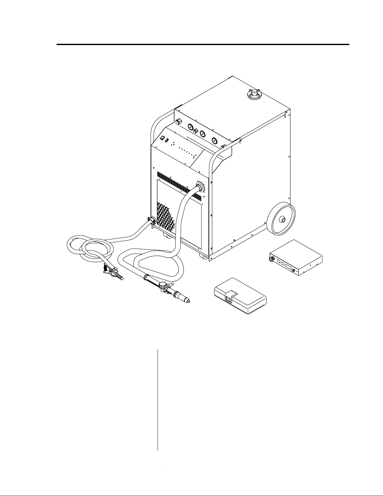
2.1 SYSTEM DESCRIPTION
PAK 15XC Power Supply
Work Cable
Figure 2-A The Merlin PAK 15XC Plasma Arc Cutting/Gouging System
The Merlin PAK 15XC
System Includes:
PCM-150 Machine Torch
• PAK 15XC 150 Amp Power Supply
• PCH-150 90° or 70° Hand Torch
• 25 ft (7.6 m) or 50 ft (15.2 m) Torch Leads
• PCH/M-150 Spare Parts Kit
• 25 ft (7.6 m) Work Cable and Clamp
• Running Gear and Handle
• Air Line Filter Assembly (or) High Pressure Regulators
NOTE
System options and accessories are listed in Section 2.4.
Torch Leads
Remote Control Panel
A-00875
Spare Parts Kit
with Running Gear and Handle
(or) PCM-150 Machine Torch with Mounting Assembly
Manual 0-2251 9 INTRODUCTION & DESCRIPTION
Page 14

2.2 POWER SUPPLY SPECIFICATIONS
Shipping Weight
Enclosure Only:
Input Power
Output Power
Duty Cycle
A-00876
Voltage Frequency Phase Amperage
200/220/230 50 or 60 Hz 3 84/76/73
380/415/460 50 or 60 Hz 3 44/40/36
500/575 50 or 60 Hz 3 34/29
Table 3-A (page 23) contains information on power input,
current ratings, circuit protection, and wire sizes.
Continuously adjustable from 50 to 150 amps
100% duty cycle.
Approximate Shipping Weight - 678 lbs (308 kg)
34.25 in
24.12 in
(0.61 m)
(0.87 m)
Figure 2-B Power Supply Dimensions
38.38 in
(0.98 m)
Fully Assembled:
Width: 28.50 in (0.72 m)
Height: 43.38 in (1.10 m)
Depth: 43.75 in (1.11 m)
INTRODUCTION & DESCRIPTION 10 Manual 0-2251
Page 15

2.3 TORCH SPECIFICATIONS
Torch Configurations
Torch Leads Lengths
Current Rating
Cutting Range
Gas Requirements
• PCH-150 90° Hand Torch
• PCH-150 70° Hand Torch
• PCM-150 Machine Torch
Standard lengths of 25 ft (7.6 m) or 50 ft (15.2 m).
Extendable in increments of 25 ft or 50 ft up to a maximum
of 150 ft (45.7 m) with available leads extension packages
(see Section 2.4, Options and Accessories)
150 Amps Maximum, Direct Current Straight Polarity
Hand and Machine Torch rated at 100% Duty Cycle
Most materials up to 2.0 in (50.8 mm)
Plasma
Gases
• Compressed Air
• Oxygen (O
2)
• Argon/Hydrogen
(Ar/H
• Nitrogen (N
2)
2)
Pressure
50 psi
(3.4 BAR,
340 kPa)
Hot Flow *
For Cutting:
22-28 scfh
(10.4-13.2 lpm)
For Gouging:
22-43 scfh
(10.4-20.3 lpm)
Secon-
dary
• Compressed Air
• Nitrogen (N
2)
• Carbon Dioxide
(CO
2)
• Water
50 psi
(3.4 BAR,
340 kPa)
Min.50 psi
(3.4 BAR,
340 kPa)
For Cutting or
Gouging:
220 scfh
(103 lpm)
8 gph
(30.3 lph)
NOTE
* Hot flow is measured with the main arc activated. When
pressure is set correctly the plasma gas flow rate is
significantly higher until the arc is initiated.
PCH-150 90° Hand Torch (without Leads) - 1.0 lb (.45 kg)Weight
(continued)
Manual 0-2251 11 INTRODUCTION & DESCRIPTION
Page 16
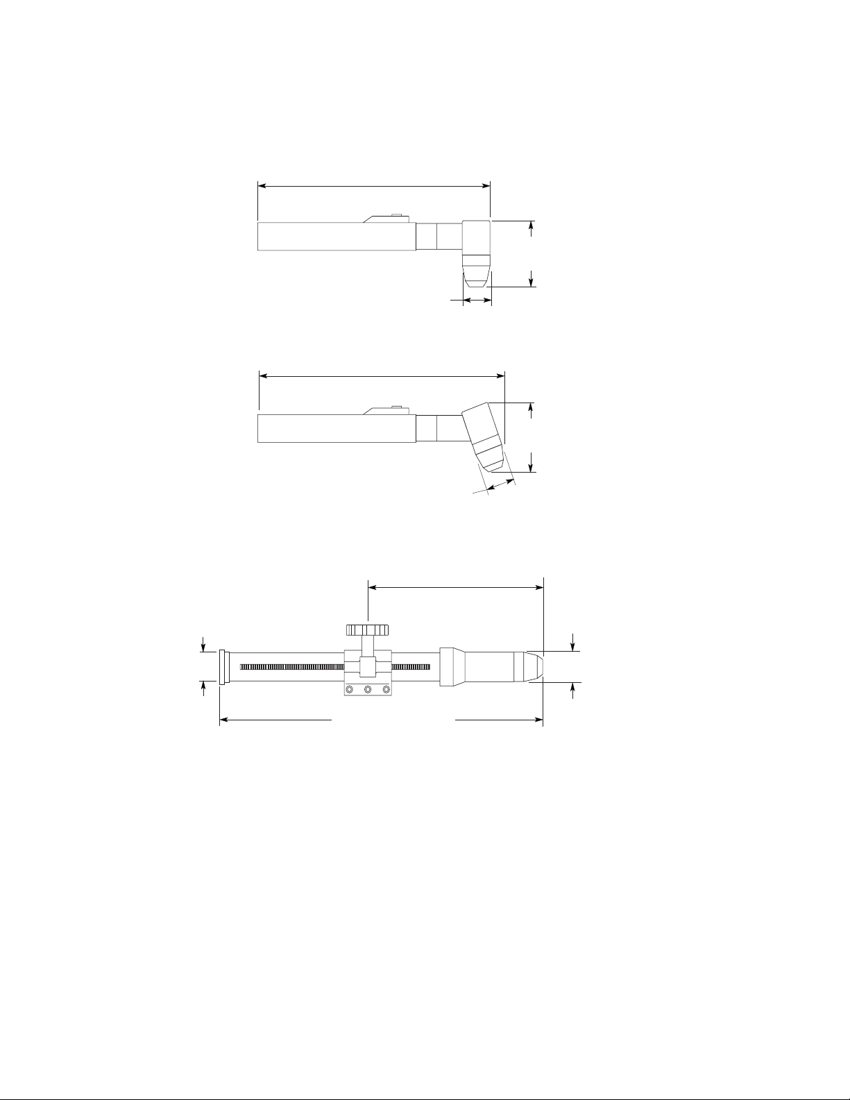
2.3 TORCH SPECIFICATIONS (continued)
PCH-150 90o Hand Torch
13.31 in
(338 mm)
1.62 in
(41 mm)
o
PCH-150 70
Hand Torch
13.87 in
(352 mm)
1.62 in
(41 mm)
3.81 in
(97 mm)
3.96 in
(101 mm)
1.38 in
(35 mm)
PCM-150 Machine Torch With Rack
And Pinion Mounting Assembly
6.75 in (171 mm) Min.
16.75 in (425 mm) Max.
17.65 in (448 mm)
Figure 2-C PCH/M-150 Torch Dimensions
1.62 in
(41 mm)
A-02685
INTRODUCTION & DESCRIPTION 12 Manual 0-2251
Page 17

2.4 OPTIONS AND ACCESSORIES
Power Supply Options
and Accessories
NOTE
Torch Options
and Accessories
• Remote Control Panel - For machine torch systems, the
low profile operator control panel allows system control
from a remote location with 25 or 50 ft (7.6 or 15.2 m)
cable included.
• Remote Pendant Control - Hand-held remote contactor
control device for machine torch systems.
• Computer Control Cable Kits - For interfacing the
power supply with a computer or auxiliary control
device. Available in 5 or 10 ft (1.5 or 3.0 m) lengths.
• SC-5 Standoff Control - For machine torch systems, the
SC-5 automatically finds height and maintains torch
standoff with a high speed torch lifter motor.
• High Pressure Regulators - Available for air, oxygen,
argon/hydrogen, nitrogen, CO
2, and water.
See Section 6.2, System Components and Accessories for
ordering information.
• Spare Parts Kits - Kits contain replacement front-end
torch parts and tools. Spare parts kits are available for
air cutting with hand or machine torch, multi-gas
cutting with hand or machine torch, or for gouging.
NOTE
• Leads Extension Packages - Available in 25 ft (7.6 m) or
50 ft (15.2 m) lengths. For extending leads up to a
maximum of 150 ft (45.7 m).
• Metal Shield Cup - For durability in hand cutting.
See Section 6.9, Torch Components and Section 6.10, Torch
Accessories for ordering information.
Manual 0-2251 13 INTRODUCTION & DESCRIPTION
Page 18
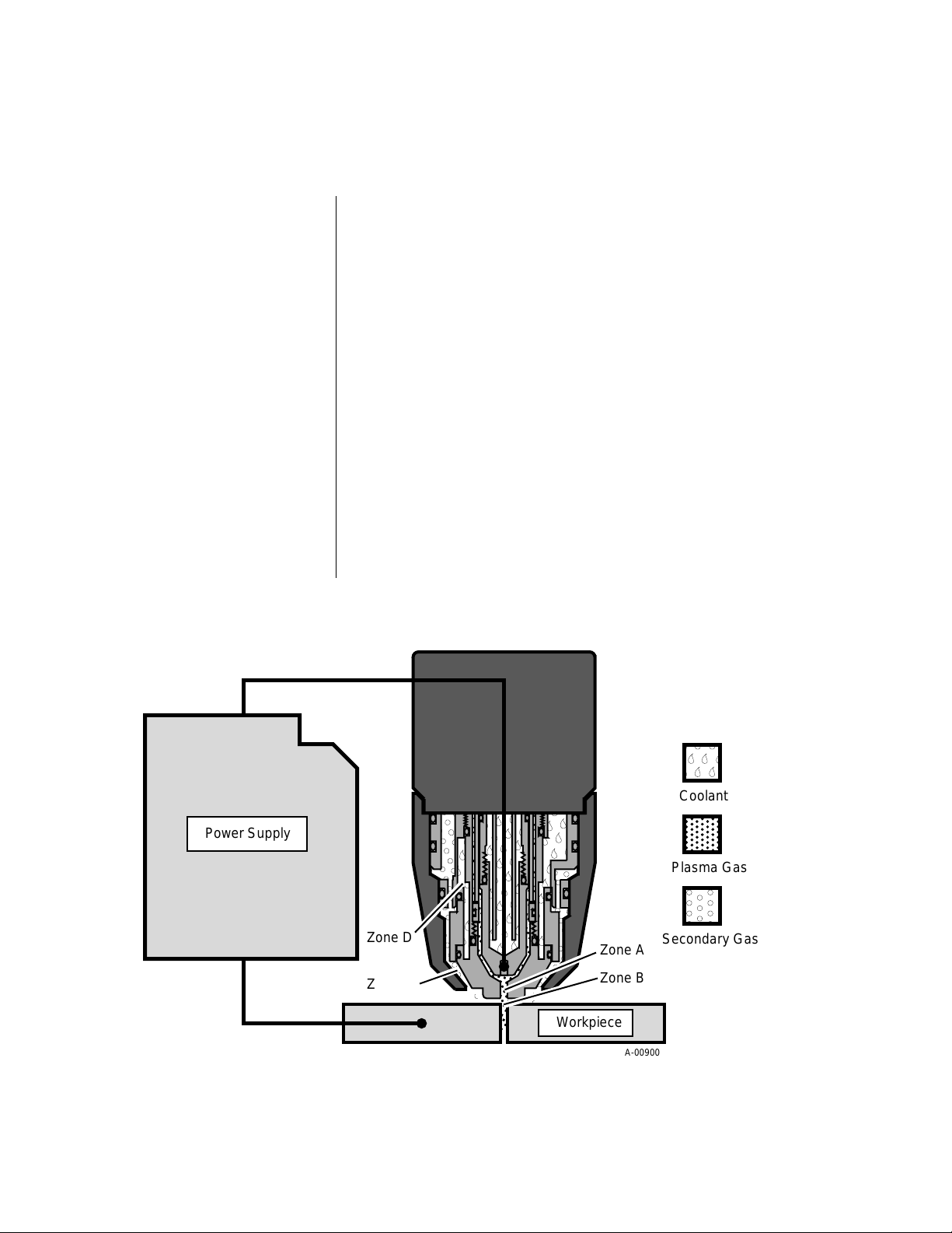
2.5 THEORY OF OPERATION
,
,
,
,
,
Plasma Arc Cutting and
Gouging
Plasma Gas Flow
Plasma is a gas which is heated to an extremely high
temperature and ionized so that it becomes electrically
conductive. The plasma arc cutting process uses this
plasma to transfer an electric arc to a workpiece. The
metal to be cut is melted by the intense heat of the arc and
then blown away. The Merlin PAK 15XC is a high performance plasma cutting system designed to cut most
metals up to two inches thick.
With a simple change of torch parts, the system can also be
used for plasma arc gouging. Plasma arc gouging is used
to remove material to a controlled depth and width.
The torch uses a cool plasma gas such as compressed air,
nitrogen, argon/hydrogen, or oxygen. The plasma gas
flows into the torch through the plasma torch lead and is
channelled into Zone A (Figure 2-D), where a pilot arc
between the torch electrode and tip heats and ionizes the
gas. The main cutting arc transfers to the workpiece
through the column of plasma gas as it flows out through
the torch tip orifice.
Power Supply
(-)
Zone D
Zone C
(+)
Figure 2-D Theory of Operation
Zone A
Zone B
Workpiece
Coolant
Plasma Gas
Secondary Gas
A-00900
INTRODUCTION & DESCRIPTION 14 Manual 0-2251
Page 19

2.5 THEORY OF OPERATION (continued)
Plasma Gas Flow
(continued)
Secondary Flow
Coolant Flow
By forcing the plasma gas and arc through a consrticted
orifice, the torch delivers a high concentration of heat to a
small area. The stiff, constricted plasma arc is shown in
Zone B (Figure 2-D). Direct current (DC) straight polarity
is used for plasma cutting, as shown in the illustration.
The torch also uses a secondary gas (or water) which
assists the high velocity plasma gas in blowing molten
metal from the area of the cut to create a fast, slag-free cut.
The secondary flow (Zone C, Figure 2-D) also cools the
torch and minimizes heat input to the workpiece. The
secondary flows into the torch through the secondary lead,
down around the outside of the torch liner, and out between the tip and shield cup around the plasma arc.
Compressed air, supplied by either a cylinder or plant air
system, nitrogen, CO
2, or water can be used as the secon-
dary. An exception to this is oxygen plasma operation,
which requires no secondary.
The torch is liquid-cooled by an internal closed cooling
system. De-ionized coolant is distributed from a reservoir
in the power supply through the coolant supply lead. At
the torch, the coolant is circulated around the torch tip and
electrode (Zone D, Figure 2-D), where the extra cooling
effect helps to increase parts life. The coolant then flows
back to the power supply through the return lead.
Pilot Arc
Main Cutting Arc
RF Shielding
When the torch is started, a DC pilot arc is established
between the electrode and cutting tip after a two-second
pre-flow delay. The pilot arc is initiated by a momentary
high frequency pulse. The pilot arc creates a path for the
main cutting arc to transfer to the work. When the main
arc is established, the pilot arc shuts off. The pilot automatically restarts when the main arc stops, as long as the
torch remains activated.
The PAK 15XC accepts 50 or 60 Hz three-phase line input.
An internal changeover switches input line voltages in
three ranges, for 200/220/230V, 380/415/460V, or 500/
575V operation. The power supply converts AC input
power to DC power for the main cutting arc. The negative
output is connected to the torch electrode through the
negative torch lead. The positive output is connected to
the workpiece via the work cable and clamp connection.
All machine torch systems are shielded to minimize radio
frequency (RF) interference which results from the high
frequency arc initiation. These shielded systems are designed with features such as a wire for establishing an
earth ground and shielded torch and control leads.
Manual 0-2251 15 INTRODUCTION & DESCRIPTION
Page 20

2.5 THEORY OF OPERATION (continued)
Interlocks
Parts-In-Place Interlock
Gas Pressure Interlock
Thermal Interlock
The system has several built-in interlocks to provide safe
and efficient operation. When an interlock shuts down the
system, the torch switch (or control device) must be used
to restart the system.
The torch has a built-in parts-in-place interlock that prevents accidental torch starting when torch parts are not
properly installed. A flow switch on the coolant return
lead detects reduced coolant flow caused by improper
torch assembly. If not satisfied, the switch interrupts
power to the tip and electrode.
Pressure switches act as an interlock for the gas supplies. If
supply pressure falls below minimum requirements the
pressure switches will open, shutting off the power to the
contactors, and the GAS indicator will go out. When
adequate supply pressure is available the pressure
switches close, allowing power to be resumed for cutting.
Thermal overload sensors are located in the transformer
and main heatsink in the power supply. If one of these
components is overheated the appropriate switch will
open up, causing the temperature light to turn from green
to red and shutting off power to the main contactor. When
the overheated component cools down the switch will
close again and allow operation of the system.
INTRODUCTION & DESCRIPTION 16 Manual 0-2251
Page 21
SECTION 3: INSTALLATION PROCEDURES
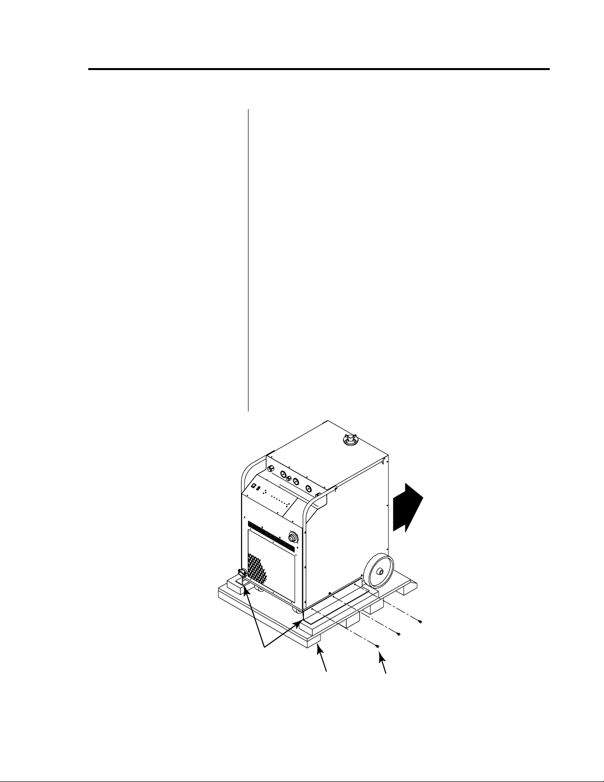
3.1 UNPACKING THE SYSTEM
The power supply is skid-mounted and protected with a
carton and padding material to prevent damage during
shipment. The power supply, work cable, torch, and torch
leads are factory-assembled and packaged together. Also
packed with the system are:
1. Remove all packing material.
2. Locate the packing list. Use the list to identify and
3. Inspect each item for possible shipping damage. If
The unit is mounted on the skid with two brackets. To
remove the unit from the skid, refer to Figure 3-A and:
• Spare parts kit for the torch
• Coolant de-ionizing cartridge
• Air filter assembly (for air systems)
account for each item.
damage is evident, contact your distributor before
proceeding with system installation.
4. Remove the six bolts connecting the brackets to the
base of the unit.
5. Roll the unit off the skid backwards (rear wheels first).
Shipping Brackets
A-00953
Shipping Pallet
Three Bolts
(Each Side)
Figure 3-A Unpacking the System
Manual 0-2251 17 INST ALLATION PROCEDURES
Page 22

3.2 LOCATION
Choosing the Location
Select a clean, dry location with good ventilation and
adequate working space around all components.
The power supply is air cooled and air flow through the
front, rear, and side panels must not be obstructed. At least
two feet (0.61 m) of clearance should be provided on all
sides.
CAUTION
Operation without proper air flow will inhibit proper
cooling and reduce duty cycle.
Review Operating Precautions (page iv) to be sure that the
selected location meets all safety requirements.
3.3 PLASMA AND SECONDARY CONNECTIONS
Plasma Gas Requirements
Compressed air, oxygen (O2), nitrogen (N2), or argon/
hydrogen (Ar/H
2).
Pressure 50 psi (3.5 BAR)
Secondary Gas
Requirements
Secondary Water
Requirements
NOTE
CAUTION
Flow 22 - 28 scfh (10.4 - 13.2 lpm) For Cutting
22 - 43 scfh (10.4 - 20.3 lpm) For Gouging
Compressed Air, nitrogen (N
2), or carbon dioxide (CO2).
Pressure 50 psi (3.5 BAR)
Flow 220 scfh (103 lpm) For Cutting or Gouging
Tap Water
Pressure Min. 50 psi (3.5 BAR)
Flow 8 gph (30.3 lph) For Cutting
See Section 4.4, Gas Selection for Plasma Cutting, for
detailed information on operation with various plasma
and secondary options.
Maximum input gas pressure to the power supply's internal regulator must not exceed 125 psi (8.6 BAR).
INST ALLATION PROCEDURES 18 Manual 0-2251
Page 23
3.3 PLASMA AND SECONDARY CONNECTIONS (continued)
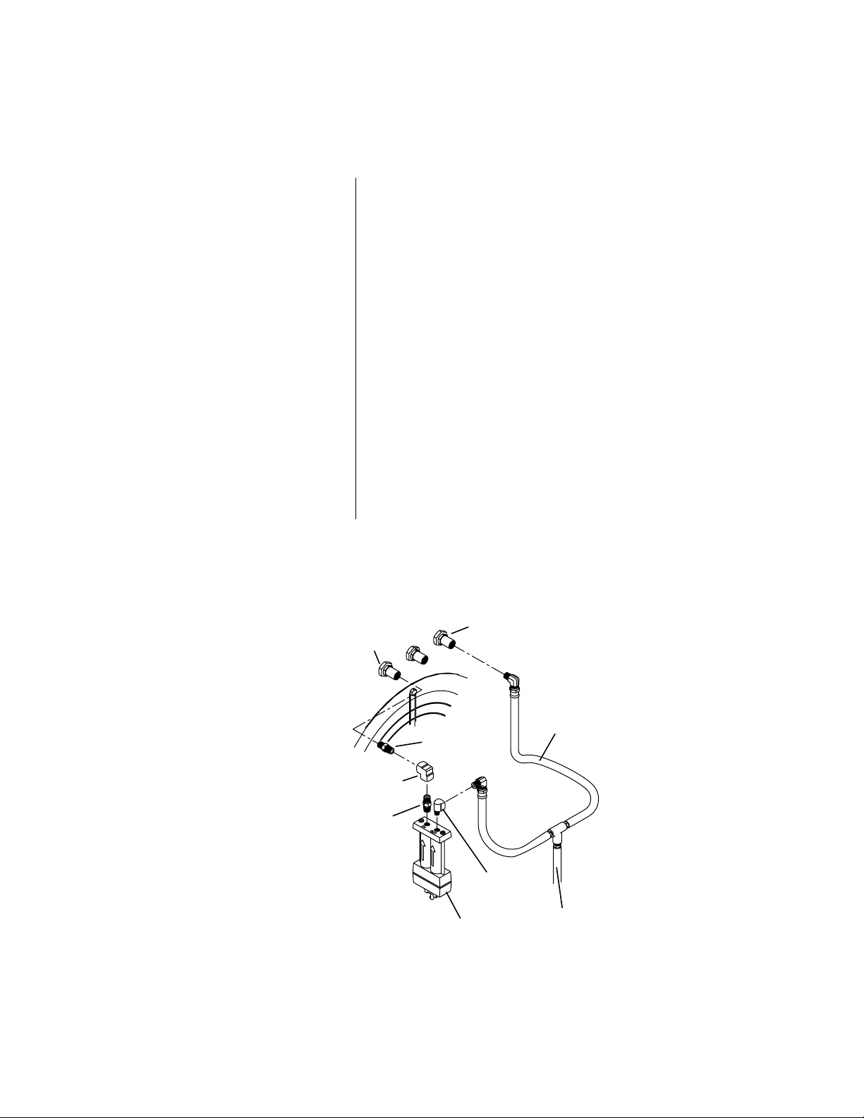
Input Gas Connections
(Air Operation)
Air Line Filter Installation
Systems that are set up for operation with shop air require
installation of the air line filter on the plasma input fitting
on the rear panel. These systems are shipped with the
following components:
(1) Air Line Filter Assembly (For Plasma Line)
(2) Hex Nipples
(1) 90° Female Elbow
(1) 90° Street Elbow
(1) Y-Hose Assembly
Refer to Figure 2-B and:
1. Thread the first hex nipple into the 90° female elbow.
2. Thread the other end of the hex nipple into the outlet
of the air filter assembly. Tighten both sides securely.
3. Thread the second hex nipple into the fitting on the
rear panel marked PLASMA.
4. Thread the 90° street elbow into the inlet side of the air
filter assembly.
(continued)
Secondary Gas
Plasma Gas
Fitting
Hex Nipple
Female Elbow
Hex Nipple
Air Filter Assembly
(Plasma Line Only)
Fitting
Y-Hose
Assembly
Street Elbow
From Supply
Figure 3-B Air Line Filter Installation
A-00902
Manual 0-2251 19 INST ALLATION PROCEDURES
Page 24
3.3 PLASMA AND SECONDARY CONNECTIONS (continued)
Air Line Filter Installation
(continued)
Input Gas Connections
(Multi-Gas Operation)
WARNING
5. Connect one side of the Y-hose assembly into the other
side of the 90° street elbow.
6. Thread the 90° female elbow onto the other end of the
second hex nipple. Fasten both sides securely.
7. Connect the other side of the Y-hose assembly to the
fitting on the rear panel marked SECONDARY.
8. Connect the supply line from the source to the Y-hose
assembly. The supply hose must be 3/8 in (10 mm)
min. inside diameter to provide adequate air flow.
1. Examine the cylinder valves to be sure they are clean
and free of oil, grease or any foriegn material. Momentarily open each cylinder valve to blow out any dust
which may be present.
Do not stand in front of the valve outlet when opening.
2. Each cylinder must be equipped with an adjustable
high-pressure regulator capable of pressures up to 125
psi (8.6 BAR) maximum and flows of up to 220 scfh
(103 lpm) for cutting or 470 scfh (222 lpm) for gouging.
CAUTION
Maximum input pressure to the power supply's internal
regulator must not exceed 125 psi (8.6 BAR).
Refer to the regulator manufacturer's specifications for
installation and maintenance procedures. Refer to
Section 6.2, System Components and Accessories, for a
listing of available high-pressure regulators.
3. Connect the plasma supply hose (black) to the plasma
gas cylinder and to the input fitting on the rear panel
marked PLASMA.
4. Connect the secondary supply hose (yellow) to the
secondary gas cylinder and to the input fitting on the
rear panel marked SECONDARY.
NOTE
A typical 50 lb. CO
2 cylinder can deliver a continuous flow
rate of 35 scfh (16.5 lpm). To obtain the required flow rate
for the torch, it may be necessary to manifold several CO
2
cylinders. Continuous flow requirements will depend on
the specific application and duty cycle.
INST ALLATION PROCEDURES 20 Manual 0-2251
Page 25
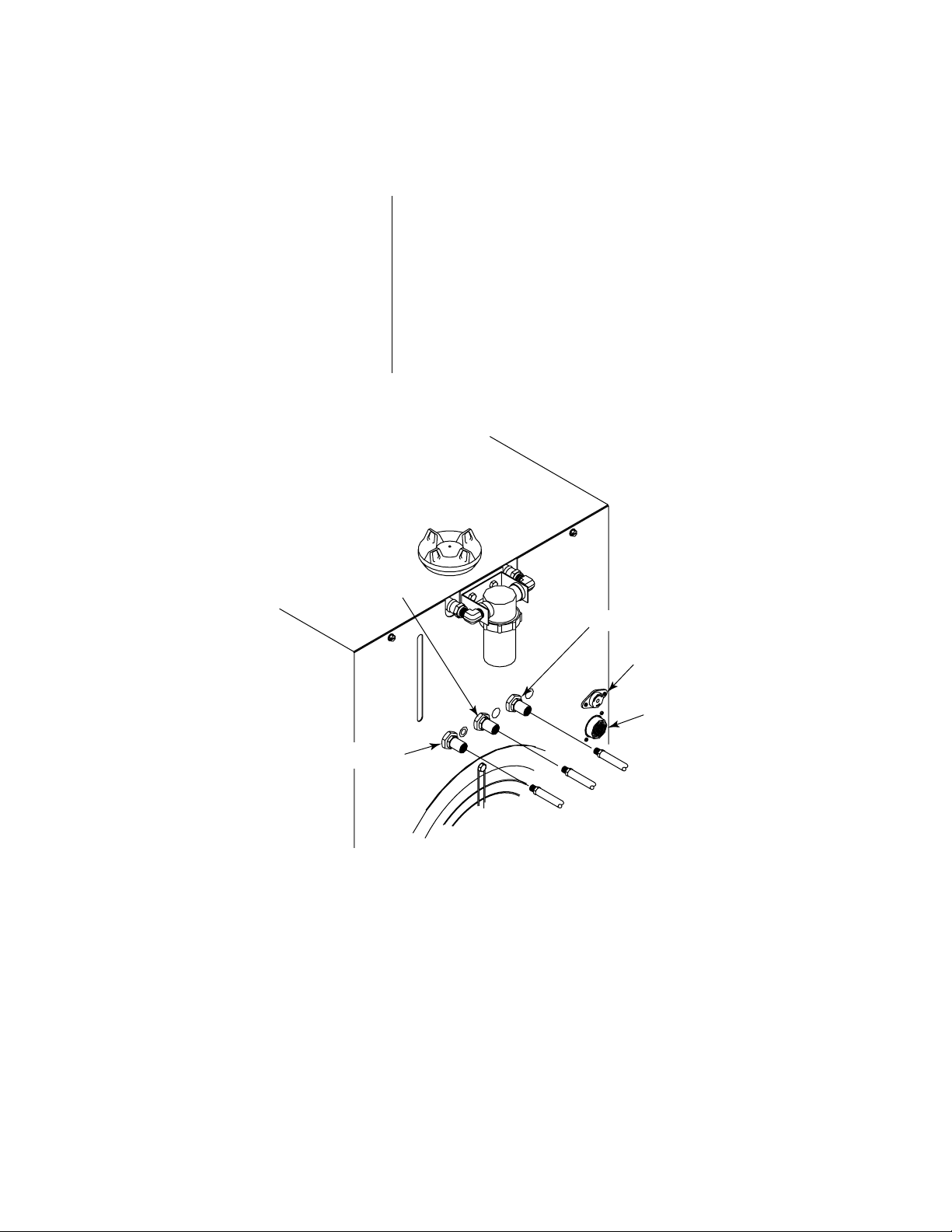
3.3 PLASMA AND SECONDARY CONNECTIONS (continued)
Secondary Water
Connections
NOTE
Secondary Water
1. The water source must be capable of delivering a
minimum water pressure of 50 psi (3.5 BAR) and flow
of 8 gph (30.3 lph).
2. Connect the secondary water supply hose to the rear
panel fitting marked SEC. WATER.
The water source does not need to be deionized, but in
water systems with extremely high mineral content a
water softener is recommended.
Secondary Gas
High Flow
Water Shield
Remote Interface
Connection
Plasma Gas
A-00874
Figure 3-C Rear Panel Connections
Manual 0-2251 21 INST ALLATION PROCEDURES
Page 26
3.4 ELECTRICAL CONNECTIONS
Electrical Requirements
Electrical Connections
WARNING
The PAK 15XC power supply is designed to accept a
variety of input voltages:
• 200/220/230 VAC
• 380/415/460 VAC
• 500/575 VAC
The electrical power source must conform to local electric
code and the following recommended circuit protection
and wiring requirements (see Table 3-A).
1. Check the three-phase electrical power source for line
voltage and proper circuit protection and wiring (see
Table 3-A).
Disconnect primary power at the source before connecting the primary power cable to the power supply.
Refer to Figure 3-D and:
2. Remove the left side panel of the power supply (as
viewed from the front).
3. Check the bus bar configuration on the input voltage
terminal board . The bus bar configuration must
correspond with the available line voltage.
4. If necessary, re-position the bus bars to correspond to
the available line voltage.
5. Insert the primary power cable through the strain relief
in the rear panel of the power supply.
6. Connect the electrical ground wire to the ground lug
on the base of the unit.
7. The other three leads attach to terminals L1, L2, and L3
on the input terminal board.
INST ALLATION PROCEDURES 22 Manual 0-2251
Page 27
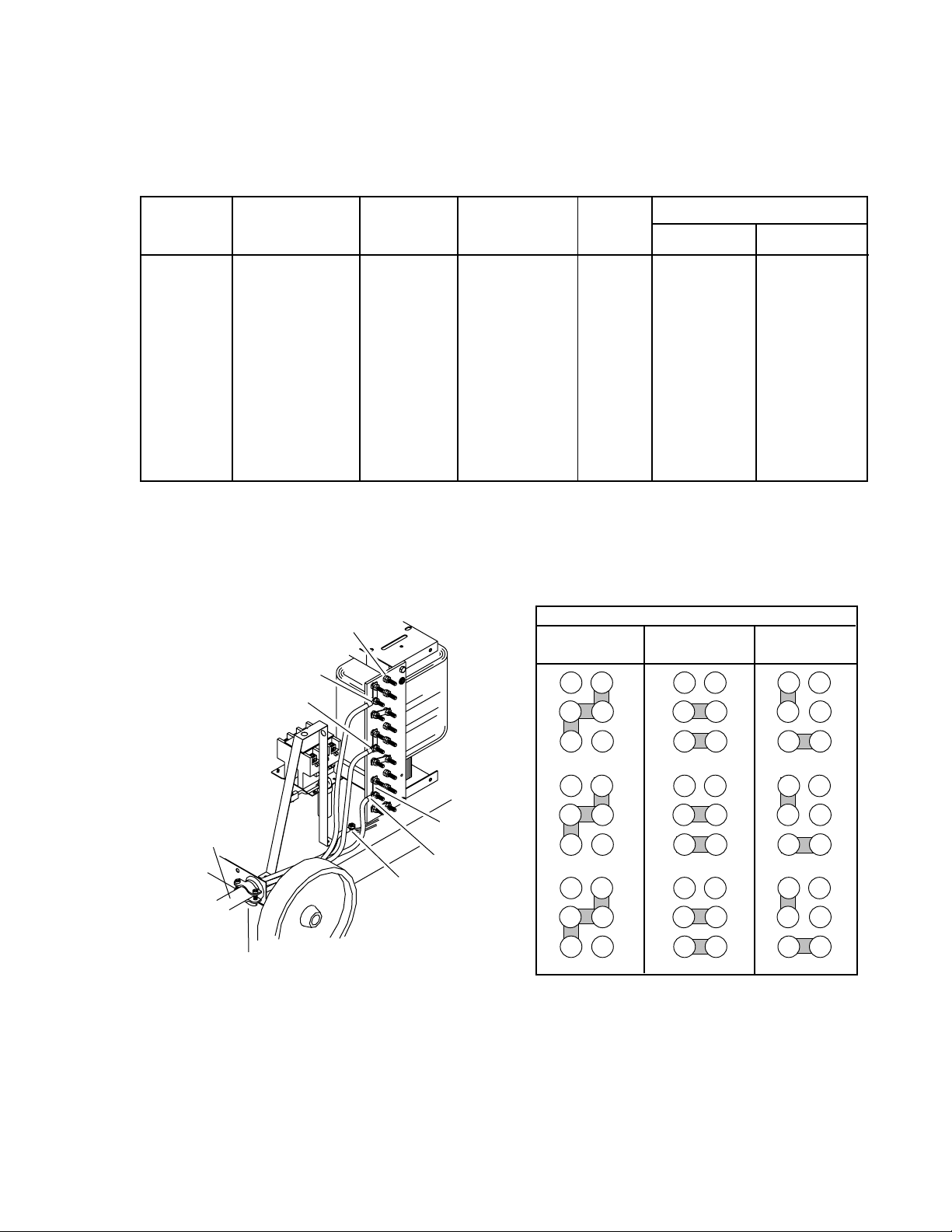
3.4 ELECTRICAL CONNECTIONS (continued)
200, 208,
220, or 230
11
12
L3
13
15
14
6
7
L2
8
10
9
1
2
L1
3
5
4
380, 415,
or 460
11
12
L3
13
15
14
6
7
L2
8
10
9
1
2
L1
3
5
4
500, or 575
11
12
L3
13
15
14
6
7
L2
8
10
9
1
2
L1
3
5
4
Busbar Connections For Input Voltages
A-00904
Voltage Power Input Current Frequency Phase Recommended
(Volts) (kVA) (Amps) (Hz) Fuse Size Wire Size
200 29 84 50 3 90 amps AWG 4
208 29 81 60 3 90 amps AWG 4
220 29 76 50 3 90 amps AWG 4
230 29 73 60 3 90 amps AWG 6
380 29 44 50 3 50 amps AWG 8
415 29 40 50 3 45 amps AWG 8
460 29 36 60 3 40 amps AWG 10
500 29 34 50 3 40 amps AWG 10
575 29 29 60 3 35 amps AWG 10
Table 3-A Line Voltages, Circuit Protection and Recommended Wire Size
(Based on Table 310-16, 1987 National Electric Code).
Primary Power
Cable
Input Voltage
Terminal Board
L3
L2
Busbars
L1
Strain Relief
Fitting
Figure 3-D Input Voltage Connections and Bus Bar Configuration
Ground
Connection
A-00893
Manual 0-2251 23 INST ALLATION PROCEDURES
Page 28
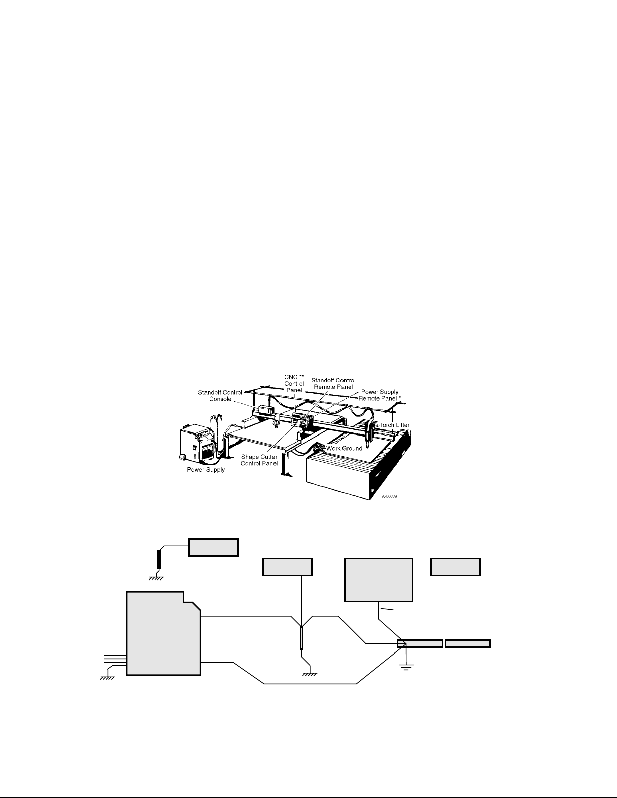
3.5 WORK AND GROUND CONNECTIONS
Machine torch systems are equipped with shielded torch
leads to minimize RF interference from high frequency
pilot arc initiation. Follow these grounding procedures
when installing machine torch systems:
1. Connect the ground wire (from the front panel) to a
solid earth ground, which is created by driving a
copper rod approximately 7 ft (2 m) into the earth.
Locate the rod as close as possible to the power supply.
Cut the ground wire to the appropriate length.
2. The power supply and work table should be grounded
to the same earth ground. The control device should be
grounded separately to a similar earth ground.
3. To minimize RF interference, torch leads should be run
as far as possible from any CNC components, control
lines, or primary power lines.
4. Connect work ground cables as shown (Figure 3-E).
3-Phase
Input
Earth
Ground
Power
Supply
Power Supply
Remote Panel
CNC Control
Earth
Ground
Work
Cable
Standoff Control
Console
Green Cable
(Work Ground)
Standoff Control
Remote Panel
Workpiece
Work Ground
A-00880
Figure 3-E Proper Work and Ground Cable Connections
INST ALLATION PROCEDURES 24 Manual 0-2251
Page 29
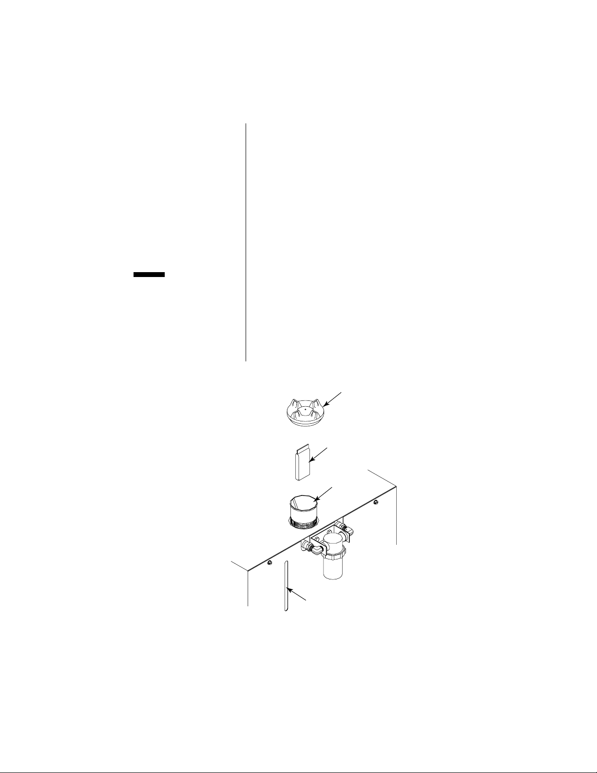
3.6 COOLANT INSTALLATION
Coolant Installation
CAUTION
Refer to Figure 3-F and:
1. Locate the coolant de-ionizing cartridge and remove
from the plastic shipping bag.
2. Remove the plastic cover from the coolant reservoir
filler.
3. Place the de-ionizing cartridge into the basket in the
coolant reservoir.
4. Fill the reservoir to the line marked FULL on the rear
panel.
Use only Thermal Arc torch coolant. Use of any other
coolant can result in torch damage, insufficient thermal
protection, and/or pilot arc interference.
The deionizer cartridge should be checked periodically.
The contents of the cartridge take on a light straw-colored
appearance when spent. Replace the cartridge when the
material has completely changed color.
Coolant Reservoir
Filler Cap
Deionizer
Bag
Basket
A-00872
Coolant Level Indicator
Figure 3-F Coolant Reservior and De-ionizing Cartridge
Manual 0-2251 25 INST ALLATION PROCEDURES
Page 30

3.7 AUXILIARY CONNECTIONS
Remote Operator Control
Panel Installation
Computer Control Interface
Installation
SC-5 Standoff Control
Installation
High-Flow Water Shield
Installation
The Remote Operator Control Panel consists of the control
panel enclosure and cables required for connection.
1. Connect the control cable to the receptacle marked
REMOTE (J15) on the rear panel.
2. Connect the other end of the control cable to the
receptacle marked PS (J37) on the remote operator
control panel enclosure.
1. Connect the interface cable to the receptacle marked
CNC (J29) on the remote operator control panel.
2. Connect the other end to the customer-supplied motion control device (refer to Appendix IV, CNC Interface).
The SC-5 Standoff Control consists of a control panel, an
electronic unit, a voltage divider board, a torch lifter
motor, and cables required for installation (refer to Figure
3-G). It is ordered and shipped separately and must be
installed according to the SC-5 Standoff Control Instruction Manual, which is included with the SC-5 unit.
Refer to the High-Flow Water Shield Instruction Manual
and:
1. Connect the high-flow starter control cable to the
receptacle marked HI-FLOW WATER SHIELD on the
power supply rear panel. The receptacle is 115VAC to
activate the high-flow water shield.
2. To shut off the high-flow water shield remove the
control cable or disconnect power to the high-flow
water shield unit.
INST ALLATION PROCEDURES 26 Manual 0-2251
Page 31

3.7 AUXILIARY CONNECTIONS (continued)
POWER
SUPPLY
CNC
CONTROL
SC-5
D
CONTROL
B
CONSOLE
E
SC-5 REMOTE
CONTROL
A
C
F
POWER SUPPLY
REMOTE CONTROL
Cable Description Letter Designation
SC-5 Remote to Console A
SC-5 Torch Lifter (Positioner) to Console B
WORK
GROUND
TORCH
POSITIONER
(LIFTER)
A-00879
SC-5 Console to Power Supply Remote C/F
SC-5 Console to Power Supply D
SC-5 Console to Work (Ground) E
NOTE - See Catalog Pages for ordering information.
Figure 3-G Typical Mechanized System Installation and Cable Interconnection Diagram
Manual 0-2251 27 INST ALLATION PROCEDURES
Page 32

3.8 LIFTING THE POWER SUPPLY
WARNING Do not lift the power supply by the handles.
CAUTION
Do not lift a power supply equipped with a cylinder rack
running gear.
The recommended method for lifting the power supply is
to use a forklift (see Figure 3-H). Approach from the front
or rear of the unit. Place the forks between the rear wheels
or the front casters. Center the forks under the unit and
carefully check for proper balance before lifting.
Approach From Front Or Rear
Do Not Lift From Sides
A-00873
Figure 3-H Lifting the Power Supply
INST ALLATION PROCEDURES 28 Manual 0-2251
Page 33

SECTION 4: OPERATION
4.1 OPERATING CONTROLS
1 2
7
5 6
4
8
10
9
ON
OFF
RUN
PURGE
Figure 4-A PAK 15XC Operating Control Panel
Control Indicator
1. ON/OFF Switch
2. RUN/SET/PURGE
Switch
3. Current Control
SET
GAS
COOLANT
PRES.
COND.
DC
PILOT
A-00887
100
75
50
3
125
AC TEMP
150
AMPS
Function
ON position activates all system control circuits.
OFF position deactivates control circuits.
RUN position is used for torch operation.
SET position is used for setting gas pressures.
PURGE position is for purging the plasma gas line.
Selects output current from 50 to 150 amps (see Section
4.11, Cutting Speeds, for applications on various materials
and thicknesses). Current control is disabled when Remote
Operator Control Panel is used.
4. AC Power Indicator
Green light indicates AC power is being supplied to the
system when the ON/OFF switch is in ON position.
5. TEMP Indicator
Green light indicates proper operating temperature. Red
light indicates overheating. Unit must be allowed to cool.
6. GAS Indicator
In SET position, yellow light in SET mode indicates gas
pressure switches are satisfied when gas is flowing to the
torch. Light goes out in PURGE or RUN mode.
7. Coolant Pressure Indicator
8. Coolant Conductivity
Indicator
Yellow light indicates adequate coolant pressure.
Yellow light indicates proper coolant conductivity. Light
out indicates excessive coolant conductivity (resistivity less
than 0.1 MΩ). Replace coolant and de-ionizer cartridge.
9. DC Indicator
Yellow light indicates main contactor closure supplying
voltage to the power supply output and cutting current is
available. Torch switch must be closed.
10. PILOT Indicator
Yellow light indicates pilot arc contactor closure. Light
goes out when cutting arc is established and comes back
on if cutting arc is interrupted.
Manual 0-2251 29 OPERA TION
Page 34

4.1 OPERATING CONTROLS (continued)
Figure 4-B PAK 15XC Upper Gauge Panel
Control Indicator
1. Secondary Pressure
Control
2. Secondary Pressure Gauge
3. Secondary Mode Selector
4. Coolant Pressure Gauge
5. Plasma Pressure Gauge
6. Plasma Pressure
Control
Function
Adjusts secondary gas pressure. Pull knob out and turn
clockwise to increase secondary pressure to desired level.
Displays secondary pressure from 0 - 100 psi (0 - 6.9 BAR).
Selects secondary mode to gas, oxygen (no secondary), or
water. See Section 4.4, Gas Selection For Plasma Cutting,
for applications on various materials and thicknesses.
Displays coolant pressure from 0 - 160 psi (0 - 11.0 BAR).
Displays plasma gas pressure from 0 - 100 psi (0 - 6.9
BAR).
Adjusts plasma gas pressure. Pull knob out and turn
clockwise to increase plasma pressure to desired level.
OPERA TION 30 Manual 0-2251
Page 35

4.1 OPERATING CONTROLS (continued)
1
2
35
7
6
8
9
E-STOP
A-00575
Figure 4-C PAK 15XC Remote Operator Control Panel (RC6045)
Control Indicator
1. E-STOP (Emergency Stop)
2. RUN/PURGE Switch
3. START Switch
4. Start Enable Indicator
5. STOP Switch
6. CURRENT Control
Adjustment
RUN
PURGE
START STOP
4
AMPS
A
CURRENT
A
PIERCE
DELAY
CSD
4567
3
2
1
0
SPEED
LOW HIGH
8
9
10
11
10
Function
Immediately de-activates pump, motor, and all control
circuits (logic circuit and control panel LED display remain
on).
None functional.
Activates gas flow, pilot arc, and main cutting arc.
Green light indicates remote control logic has received start
signal from control device (CNC or START switch).
Deactivates gas flow, pilot arc, and main cutting arc.
Sets output current level from 50 to 150 amps.
7. AMPS Meter
8. CSD (Corner Slowdown)
Control Adjustment
9. PIERCE DELAY Control
Adjustment
10. LOW/HIGH SPEED
Switch
Displays actual output during cutting operation. Preview
mode displays expected output before starting a cut according to the current setting. A decimal point to the right
of the display is lit whenever the meter is in preview mode.
All three decimal points remain lit when displaying corner
slowdown output or operating in corner slowdown mode.
Left and center decimal points blinking indicates PIP
(parts-in-place) circuit not satisfied.
Sets corner slowdown (CSD) output from 50 to 150 amps.
Push STOP button to display corner slowdown output
setting on AMP meter. Refer to Section 4.7, Machine Torch
Operation for operating instructions.
Provides an adjustable time delay (approximately 0-11
seconds) which delays the CNC and 'OK-to-Move' signal,
allowing time to pierce before the starting the cutting
machine. Set PIERCE DELAY to zero for immediate 'OKto-Move' signal.
None functional.
Manual 0-2251 31 OPERA TION
Page 36

4.2 PRE-OPERATION SET-UP
The pre-operation set-up procedure should be followed at
the beginning of each shift:
WARNING
Coolant Check
Torch Check
Optional Auto-Restart
Settings
Input Power Check
Disconnect primary power to the system before
disassembling the torch, leads, or power supply.
1. Check the coolant level indicator and add coolant if
necessary (see Section 3.6, Coolant Installation).
2. Check the torch for proper assembly (see Section 5.1,
Torch Maintenance). Install proper torch parts for the
application (see Section 4.3, Torch Parts Selection).
3. Select the desired pre-flow, post-flow, and auto-restart
settings (see Section 4.5, Plasma Cutting Operation).
The system is factory-set for normal auto-restart, which
allows the pilot arc to restart instantly when the cutting
arc is interrupted with the torch still activated. The
system is factory-set for two-second pre-flow and tensecond post-flow.
4. Check the power source for proper three-phase input
voltage. Make sure the input power terminal board in
the power supply is set up for the available voltage
(see Section 3.4, Electrical Connections). Connect
primary power to the system (close main disconnect
switch or plug unit in).
Plasma and Secondary
Supply Check
Line Purge
Output Selection
Plasma and Secondary
Pressure Settings
OPERA TION 32 Manual 0-2251
5. Select desired plasma and secondary (see Section 4.4,
Gas Selection For Plasma Cutting). Make sure gas
sources meet requirements (see Section 3.3, Plasma and
Secondary Connections). Check connections and turn
plasma and secondary supplies on.
6. Move the ON/OFF switch to ON position. An automatic forty second gas purge will let gas run to remove
any condensation that may have accumulated in the
torch and leads while the system was shut down. After
the purge is complete, if the RUN/SET/PURGE switch
is in SET position, gases will flow. If the switch is in
PURGE position plasma gas only will flow. If the
switch is in RUN position there will be no gas flow.
7. Select the desired current output level. Refer to Section
4.11, Cutting Speeds.
8. Move the RUN/SET/PURGE switch to SET position.
Set plasma and secondary pressures (see Section 3.3,
Plasma and Secondary Connections).
Page 37

4.2 PRE-OPERATION SET-UP (continued)
Additional Line Purge 9. If additional purging of the plasma gas line is desired,
move the RUN/SET/PURGE switch to PURGE position. In PURGE mode, with secondary mode selector
set to GAS, the GAS indicator will
only plasma gas runs and the secondary gas flow
switch is not satisfied.
10. Return the RUN/SET/PURGE switch to RUN.
The system is now ready for operation.
not come on because
NOTE
Refer to Section 3.12 for detailed block diagram of the
Sequence Of Operation.
4.3 TORCH PARTS SELECTION
WARNING
Shield Cup Selection
Disconnect primary power to the system before
disassembling the torch, leads, or power supply.
Shield Cups (See Figure 4-D) Cat. No.
• Ceramic Shield Cup (For Cutting) ........................ 9-5750
• Metal Shield Cup (For Cutting)............................. 9-5790
• Touch Cup (For Height Sensing with SC-5) ........ 9-5758
• Gouging Cup............................................................ 9-5774
Ceramic Shield Cup
(For Cutting)
Cat. No. 9-5750
Metal Shield Cup
(For Cutting)
Cat. No. 9-5790
Touch Cup
(For Height Sensing
with SC-5)
Cat. No. 9-5758
Gouging Cup
Cat. No. 9-5774
Figure 4-D Shield Cup Selection
Manual 0-2251 33 OPERA TION
Page 38

4.3 TORCH PARTS SELECTION (continued)
WARNING
CAUTION
Tip Selection
Disconnect primary power to the system before
disassembling the torch, leads, or power supply.
Do not interchange parts. Make sure both the tip and
electrode in the torch correspond with the plasma gas and
secondary being used.
Cutting tips and electrodes can be identified by the ring(s)
around the diameter (see Figure 4-E). Air tips and electrodes have no rings, oxygen tips and electrodes have
one ring, nitrogen tips and multi-gas (N
2 or Ar/H2) elec-
trodes have two rings, and argon/hydrogen tips have
three rings.
Cutting Tips - Air Plasma Cat. No.
50 Amps (.043 in) ..................................................... 9-5748
100 Amps (.055 in) ................................................... 9-5747
150 Amps (.070 in) ................................................... 9-5746
Cutting Tips - O
2 Plasma
50 Amps (.043 in) ..................................................... 9-5753
Electrode Selection
100 Amps (.057 in) ................................................... 9-5752
150 Amps (.070 in) ................................................... 9-5751
Cutting Tips - N
2 Plasma
50 Amps (.043 in) ..................................................... 9-5765
100 Amps (.052 in) ................................................... 9-5766
150 Amps (.067 in) ................................................... 9-5767
Cutting Tips - ArH2 Plasma
150 Amps (.073 in) ................................................... 9-5775
Gouging Tips - Air or Multi-Gas
85 Amps (.078 in) ..................................................... 9-5756
150 Amps (.120 in) ................................................... 9-5755
Electrodes Cat. No.
Air Plasma - Cutting ............................................... 9-5749
Oxygen Plasma - Cutting ....................................... 9-5760
Multi-Gas (N
2 or Ar/H2)- Cutting ........................ 9-5754
OPERA TION 34 Manual 0-2251
Page 39

4.3 TORCH PARTS SELECTION (continued)
Cutting Gouging
Air Plasma Oxygen Plasma Nitrogen Plasma Argon/Hydrogen Air or Multi-Gas
Air Plasma
50 Amp (.043) Tip
Cat. No. 9-5748
Air Plasma
100 Amp (.055) Tip
Cat. No. 9-5747
Air Plasma
150 Amp (.070) Tip
Cat. No. 9-5746
Air Plasma Electrode
Cutting or Gouging
Cat. No. 9-5749
O2 Plasma
50 Amp (.043) Tip
Cat. No. 9-5753
O
2 Plasma
100 Amp (.057) Tip
Cat. No. 9-5752
O
2 Plasma
150 Amp (.070) Tip
Cat. No. 9-5751
O
2 Plasma Electrode
Cutting or Gouging
Cat. No. 9-5760
N2 Plasma
50 Amp (.043) Tip
Cat. No. 9-5765
N
2 Plasma
100 Amp (.052) Tip
Cat. No. 9-5766
N
2 Plasma
150 Amp (.067) Tip
Cat. No. 9-5767
N2 or Ar/H2 Plasma Electrode
Cutting or Gouging
Cat. No. 9-5754
ArH
2 Plasma
150 Amp (.073) Tip
Cat. No. 9-5775
Gouging Tip
Air or Multi-Gas
85 Amp (.078)
Cat. No. 9-5756
Gouging Tip
Air or Multi-Gas
150 Amp (.120)
Cat. No. 9-5755
For gouging, select
proper electrode to
correspond to the
type of plasma gas
being used (same as
cutting).
Figure 4-E Tip and Electrode Selection
Manual 0-2251 35 OPERA TION
Page 40

4.4 GAS SELECTION FOR PLASMA CUTTING
• Air plasma is normally used with air secondary.
• Only clean, dry air is recommended for use as plasma
gas. Any oil or moisture in the air supply can substan-
AIR PLASMA
tially reduce torch parts life.
• Most often used on ferrous or carbon base materials to
obtain good cutting quality at faster cutting speeds.
• Provides satisfactory results on non-ferrous materials.
• Can be used in place of air plasma with air secondary or
CO
2.
NITROGEN PLASMA
ARGON/HYDROGEN
PLASMA
OXYGEN
PLASMA
• Provides much better parts life than air.
• Provides better cut quality on non-ferrous materials such
as stainless steel and aluminum.
• A good clean welding grade nitrogen should be used.
• A 65% argon/35% hydrogen mixture should be used.
• Recommended for use on thicker (1/2 inch and up) non-
ferrous materials. Ar/H
2 is not normally used for thin-
ner non-ferrous materials because less expensive gases
can achieve similar cut quality.
• Provides faster cutting speeds and high cut quality on
thicker materials to offset a higher cost.
• Poor cut quality on ferrous materials.
• Oxygen is recommended for cutting ferrous materials.
• Provides faster cutting speeds.
• Provides very smooth finishes and minimizes nitride
build-up on cut surface (nitride build-up can cause
difficulties in producing high quality welds if not removed).
Table 4-A Plasma Gas Selection for Plasma Cutting
OPERA TION 36 Manual 0-2251
Page 41

4.4 GAS SELECTION FOR PLASMA CUTTING (continued)
• Air secondary is normally used when operating with air
plasma and occasionally with nitrogen plasma.
AIR SECONDARY
• Inexpensive - reduces operating costs.
• Improves cut quality on some ferrous materials.
•CO2 secondary is used with nitrogen or Ar/H2 plasma.
2 SECONDARY
CO
NITROGEN
SECONDARY
WATER SECONDARY
• Provides good cut quality on ferrous or non-ferrous
materials.
• May reduce smoke when used with Ar/H
2 plasma.
• Nitrogen secondary is used with Ar/H2 plasma.
• Provides smooth finishes on non-ferrous materials.
• May be used with nitrogen plasma in order to operate
from one compressed gas cylinder.
• May reduce smoke when used with Ar/H
2 plasma.
• Water secondary should be used only in mechanized
applications - never in hand cutting!
• Normally used with nitrogen, Ar/H
2, or air plasma.
• Provides very smooth cut surface.
• Reduces smoke and heat input to the workpiece.
• Effective up to 1 inch maximum material thickness.
• Tap water provides low operating expense.
Table 4-B Secondary Selection for Plasma Cutting
Manual 0-2251 37 OPERA TION
Page 42

4.4 GAS SELECTION FOR PLASMA CUTTING (continued)
Cut Quality Cut quality requirements differ depending on application.
For instance, nitride build-up and bevel angle may be
major factors when the surface that is cut will be welded
after the cutting operation. Dross-free cutting is important
when finish cut quality is desired to avoid a secondary
cleaning operation.
Cut Surface
Nitride Deposits
Bevel Angle
Top-Edge Rounding
Dross Build-up
Kerf Width
• The desired or specified condition (smooth or rough) of
the face of the cut.
• Nitride deposits can be left on the surface of the cut
when nitrogen is present in the plasma gas stream. The
presence of nitrogen may create porosity if the material
is to be welded after the cutting process.
• The angle between the surface of the cut edge and a
plane perpendicular to the surface of the plate. A perfectly perpendicular cut would result in a 0° bevel angle.
• The amount of rounding on the top edge of the cut.
• Molten material which is not blown away from the cut
area and re-solidify on the base of the plate. Excessive
dross build-up may require a secondary clean-up operation after the cutting process.
• The width of the cut (or the width of material removed
during the cut).
Table 4-C contains cut quality information for each plasma
and secondary combination on a variety of materials and
thicknesses.
Kerf Width
Cut Surface
Bevel Angle
Top
Spatter
Top Edge
Rounding
Dross
Build-Up
Cut Surface
Drag Lines
A-00007
Figure 4-F Cut Characteristics
OPERA TION 38 Manual 0-2251
Page 43

4.4 GAS SELECTION FOR PLASMA CUTTING (continued)
GAS
Description
Excellent
Good
Fair
NR
NOTE
MATERIAL
THICKNESS
Cut Characteristics:
Minimum bevel (0 - 4°), minimum kerf (2 x tip orifice),
little or no dross, smooth cut surface.
Slight bevel (0 - 10°), slightly wider kerf (2-1/2 x tip ori-
fice), some dross (easily removed), medium-smooth cut
surface, slight top edge rounding.
Excessive bevel (over 10°), wide kerf (over 2-1/2 x tip
orifice), medium to heavy dross, rough cut surface, top
edge rounding.
Not Recommended.
Cut quality depends heavily on set-up and parameters
such as torch standoff, alignment with the workpiece,
cutting speed, gas pressures, and operator experience.
TYPE OF MATERIAL
Carbon Steel
Stainless Steel
Aluminum
Air Plasma
Air Secondary
Nitrogen Plasma
Air Secondary
or CO
2 Secondary
Nitrogen Plasma
Water Secondary
Ar/H
2 Plasma
N
2 or CO2
Secondary
Oxygen Plasma
Gage
Gage to 1 in.
1 to 2 in.
Gage
Gage to 1/2 in.
1/2 to 2 in.
Gage to 1/4 in.
1/4 to 1 in.
1 to 2 in.
Gage to 1/4 in.
1/4 to 1-1/4 in.
1/2 to 2 in.
Gage to 2 in.
Good/Excellent
Excellent
Excellent
Good/Excellent
Good/Excellent
Good/Excellent
Excellent
Good
NR
NR
NR
NR
Excellent
Good/Excellent
Good
Good
Good/Excellent
Good/Excellent
Good/Excellent
Good
Excellent
NR
NR
Good
Excellent
Good
Table 4-C Cut Quality: Plasma and Secondary Gas Selection
for Various Materials and Material Thicknesses
Good/Excellent
Good
Good
Good/Excellent
Good/Excellent
Good/Excellent
Good
Good/Excellent
NR
NR
Excellent
Excellent
NR
Manual 0-2251 39 OPERA TION
Page 44
4.5 PLASMA CUTTING OPERATION
Be sure the operator is equipped with proper gloves,
clothing, eye and ear protection and that all precautions at
WARNING
the front of this manual have been followed. Make sure no
part of the operator’s body comes in contact with the
workpiece when the torch switch is pressed.
CAUTION
CAUTION
WARNING
The sparks from the cutting process can cause damage to
coated, painted or other surfaces such as glass, plastic, and
metal.
Do not interchange parts. Make sure both the tip and
electrode in the torch correspond with the plasma gas and
secondary being used. (See Section 4.3, Torch Parts Selection).
Disconnect primary power to the system before
disassembling the torch, leads, or power supply.
The suggestions below should be followed in all cutting
and gouging operations:
1. Wait five minutes before setting the ON/OFF switch to
OFF after operation. This allows the cooling fan to run
to dissipate operating heat from the power supply.
2. For maximum parts life, do not operate the pilot arc any
longer than necessary.
3. Use care in handling torch leads and protect them from
damage.
4. In continuous cutting applications using CO
2, it is often
necessary to manifold four to six cylinders together to
maintain adequate flow at operating pressures.
NOTE
FREQUENTLY REVIEW THE SAFETY PRECAUTIONS
AT THE FRONT OF THIS MANUAL.
It is not enough to simply move the ON/OFF switch on
WARNING
the unit to OFF position when cutting operations have
been completed. Always open the power supply disconnect switch five minutes after the last cut is made.
OPERA TION 40 Manual 0-2251
Page 45

4.5 PLASMA CUTTING OPERATION (continued)
Auto-Restart Options
On/Off
Normal/Delayed
Pre-Flow Delay
Post-Flow Delay
The auto-restart function provides an immediate pilot arc
restart during post-flow if the torch is brought within
range of the workpiece. The power supply can be set up to
provide a variety of optional auto-restart settings.
• Auto-Restart On/Off - The auto-restart function can be
switched off completely so that the torch must be reactivated (via torch switch or control device) to restart
the pilot arc when the main arc is interrupted.
• Auto-Restart Normal/Delayed - Normal mode provides an immediate pilot arc restart when the main arc
is interrupted. Delayed mode provides a gas pre-flow
each time before the pilot arc restarts.
• Pre-Flow Delay - Pre-flow is the time interval from
when the torch is activated (start of gas flow) to pilot
arc initiation. Pre-flow duration is factory-set to two
seconds, but can be re-set to four, seven, or ten seconds
as desired.
• Post-Flow Delay - Gases continue to flow for a period
of time after the main cutting arc is interrupted and the
torch remains activated. Post-flow is factory-set to ten
seconds, but can be re-set to five, twenty, or forty
seconds as desired.
Applications
In machine torch operation, optional auto-restart settings
may be useful where:
1. The system is used for direct replacement of units not
having auto-restart for use with motion control devices.
2. Torch parts life may improve without auto-restart in
some applications by reducing excessive pilot arc time.
3. In some shape-cutting applications, immediately
restarting the main arc after the torch passes beyond
the desired cutting line (or between cuts) may not be
desirable.
4. Extended leads may require longer pre-flow duration.
5. Other special applications require various arrangements.
(continued)
Manual 0-2251 41 OPERA TION
Page 46

4.5 PLASMA CUTTING OPERATION (continued)
Auto-Restart
(continued)
On/Off (SW1)
Note: Either pole set to 1(on)
disables auto-restart function
Normal/Delayed (SW2)
Note: Either pole set to 1(on)
sets auto-restart function
Pre-Flow Delay (SW3)
Four two-pole DIP switches located on the control logic PC
board control the auto-restart functions.
Auto-Restart SW1-1 SW1-2
Mode Position Position
Normal 0 (Off) 0 (Off)
Disabled 0 (Off) 1 (On)
1 (On) 0 (Off)
1 (On) 1 (On)
Auto-Restart SW2-1 SW2-2
Mode Position Position
Normal 0 (Off) 0 (Off)
Delayed 0 (Off) 1 (On)
1 (On) 0 (Off)
1 (On) 1 (On)
Pre-Flow Time SW3-1 SW3-2
(Seconds) Position Position
Post-Flow Delay (SW4)
For Hand Cutting
Systems (A1845-01)
with 19x704 Logic PCB
Post-Flow Delay (SW4)
For Machine Cutting
Systems (A1845-15)
with 19x910 Logic PCB
2 0 (Off) 0 (Off)
4 0 (Off) 1 (On)
7 1 (On) 0 (Off)
10 1 (On) 1 (On)
Post-Flow Time SW4-1 SW4-2
(Seconds) Position Position
5 0 (Off) 1 (On)
10 0 (Off) 0 (Off)
20 1 (On) 0 (Off)
40 1 (On) 1 (Off)
Post-Flow Time SW4-1 SW4-2
(Seconds) Position Position
2.5 0 (Off) 1 (On)
5 0 (Off) 0 (Off)
10 1 (On) 0 (Off)
20 1 (On) 1 (Off)
OPERA TION 42 Manual 0-2251
Page 47
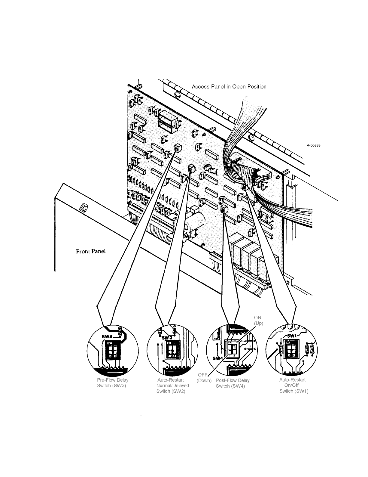
4.5 PLASMA CUTTING OPERATION (continued)
Figure 4-G Control Logic PC Board - Setting Auto-Restart Options
Manual 0-2251 43 OPERA TION
Page 48

4.6 HAND TORCH OPERATION
Be sure the operator is equipped with proper gloves,
clothing, eye and ear protection and that all precautions at
WARNING
the front of this manual have been followed. Make sure no
part of the operator’s body comes in contact with the
workpiece when the torch switch is pressed.
CAUTION
Plasma Cutting Operation
(Hand Torch)
WARNING
Cutting with a Hand Torch
The sparks from the cutting process can cause damage to
coated, painted or other surfaces such as glass, plastic, and
metal.
Do not interchange parts. Make sure both the tip and
electrode in the torch correspond with the plasma gas and
secondary being used. (See Section 4.3, Torch Parts Selection).
Disconnect primary power to the system before
disassembling the torch, leads, or power supply.
1. The hand torch should be held in both hands for making long cuts. Choose the method that feels the most
comfortable and works the best. Use the thumb to
actuate the control switch on the torch handle.
Figure 4-H Cutting with a Hand Torch
OPERA TION 44 Manual 0-2251
Page 49

4.6 HAND TORCH OPERATION (continued)
Hand Torch Operation
(continued)
NOTE
CAUTION
2. To positively locate the line of the cut, position the torch
over the workpiece, resting the front edge of the shield
cup on the edge where the cut is to start.
3. Lower the welding helmet. Press and hold the torch
control switch. After a two second gas purge, the pilot
arc will start. The pilot arc will stay on as long as the
torch control switch is held.
4. With the pilot arc on the main cutting arc is established
as soon as the torch is brought within 1/8 - 3/8 in
(3 - 10 mm) of the workpiece. If the cutting arc is interrupted and the switch is still pressed, as when cutting
expanded metal, the pilot arc will automatically restart.
Releasing the torch control switch will shut off either the
pilot or main arc (depending on the mode of operation).
5. Cut with the torch held 1/8 - 3/8 in (3 - 10 mm) from
the work. The torch should be held perpendicular to the
workpiece while cutting.
Use a standard ceramic or metal shield cup for hand
cutting. The touch cup (short shield cup) and gouging cup
Manual 0-2251 45 OPERA TION
Page 50
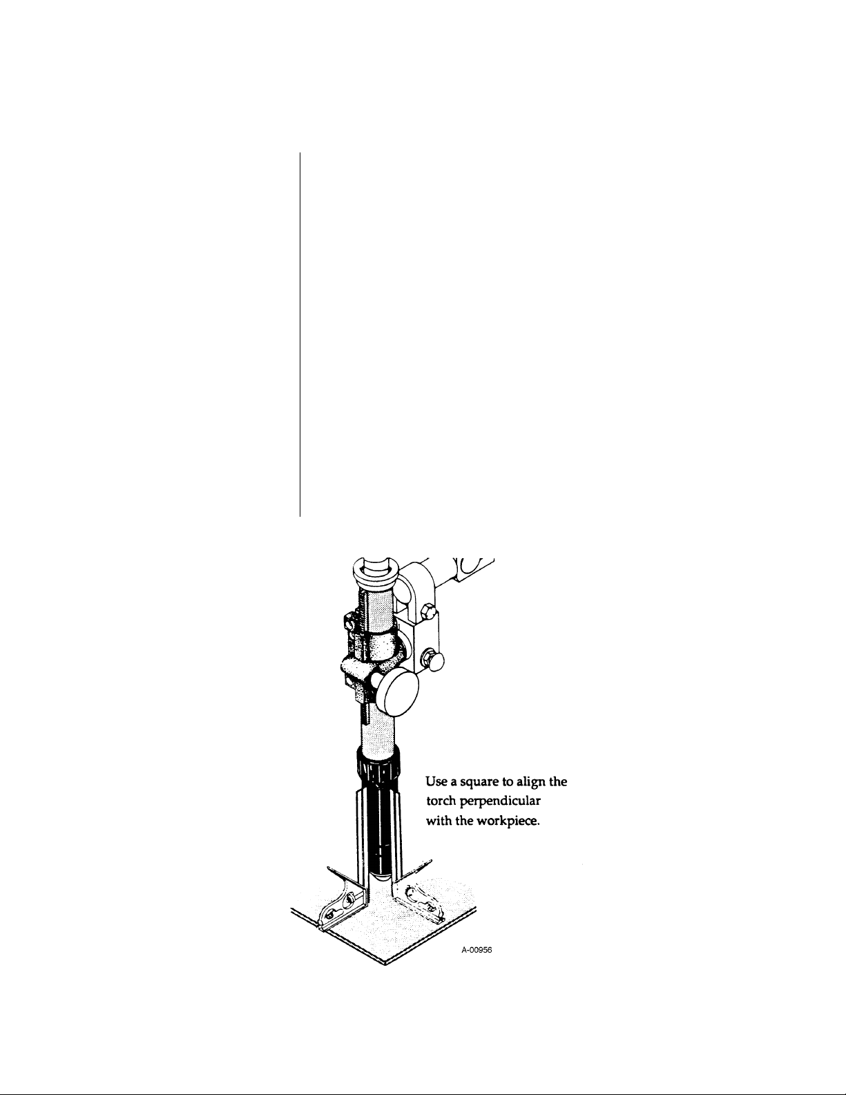
4.7 MACHINE TORCH OPERATION
Cutting with a
Machine Torch
1. A machine torch should be aligned perpendicular to
the surface of the workpiece to obtain a clean, vertical
cut. Use a square to align the torch (see Figure 4-I).
2. Position the center of the torch over the edge of the
workpiece where the cut is to start. The transferred
cutting arc will then be established at the plate edge
when the torch is activated.
3. The machine torch can be activated by the remote
operator control panel, remote control pendant, or by
remote interface device such as CNC. After a two
second gas purge, the pilot arc will start. The pilot arc
will stay on as long as the torch is activated.
4. With the pilot arc on the main cutting arc is established
as soon as the torch is brought within 1/8 - 3/8 in (3 10 mm) of the workpiece. If the cutting arc is interrupted and the torch is still activated, as when cutting
expanded metal, the pilot arc will automatically restart
(see Section 4.5, Plasma Cutting Operation, AutoRestart Options). De-activating the torch will shut off
either the pilot or main arc (depending on the mode of
operation).
Figure 4-I Machine Torch Set-up
OPERA TION 46 Manual 0-2251
Page 51

4.7 MACHINE TORCH OPERATION (continued)
Cutting with a
Machine Torch
(continued)
5. Cut with a standoff of 1/8 - 3/8 in (3 - 10 mm) from the
work. The torch should be held perpendicular to the
workpiece while cutting. Start cutting slowly and
adjust cutting speed for optimum cutting performance.
Section 3.11, Cutting Speeds, contains typical cutting
speeds for various materials and material thicknesses.
A standard shield cup is recommended for most machine
cutting applications. The touch cup (short shield cup) is
designed for light gage cutting where arc voltage measurement is needed for a standoff control. Do not allow an
exposed torch tip to contact the workpiece.
The arc characteristics vary with gases used, cutting speed,
material, and thickness. Air plasma normally produces a
straight arc (on stainless or aluminum), while nitrogen
plasma generally creates a 5° trailing arc (see Figure 4-J).
Figure 4-J Machine Torch Operation
Manual 0-2251 47 OPERA TION
Page 52

4.7 MACHINE TORCH OPERATION (continued)
Corner Slowdown (CSD)
NOTE
Corner Slowdown Settings
The corner slowdown feature provides an output current
reduction in to correspond with the reduction in torch
travel speed as a mechanized torch moves through a
corner. When activated by CNC or other control device,
the corner slowdown eliminates excessive metal removal
in corners.
Normally open (NO) contacts (supplied by the control
device) close when the torch travel speed decreases
through a corner. When the contacts close, power supply
output drops to a pre-set current level.
A two-pole DIP switch in the remote operator control
panel PC board allows the corner slowdown to operate
with normally closed (NC) contacts in the control device if
desired.
Corner slowdown adjustment is located on the remote
operator control panel (see Section 4.1, Operating Controls).
The control is factory set fully counter-clockwise for
minimum 50 amps output during corner slowdown. Turn
the control clockwise to increase corner slowdown output.
When the control is turned fully clockwise, corner slowdown output is increased to a maximum 150 amps.
NOTE
To view the corner slowdown setting, press and hold the
stop control. The expected CSD output level will be displayed on the ammeter.
In the PAK 15XC, the corner slowdown setting is independent (
example, if CSD current is set to 100 amps, and main
cutting current is set to the minimum 50 amps, the actual
current level would actually
cycle.
For electrical connections, refer to Appendix IV, CNC
Interface.
not a percentage) of the main current setting. For
increase through the CSD
OPERA TION 48 Manual 0-2251
Page 53

4.8 PIERCING
In some cutting operations, it may be desirable to start the
cut within the plate area rather than at the plate edge.
Piercing the plate is not recommended on plates having a
thickness greater than 3/4 in (19 mm). Blowback from the
piercing operation can shorten the life of torch parts. All
piercing should therefore be done as quickly as possible
and at maximum amperage (150 amps) and maximum
standoff.
Piercing with a Hand Torch
When piercing with a hand torch, tip the torch slightly so
that blowback particles blow away from the torch tip (and
operator) rather than directly back into it (see Figure 4-K).
Pierce off the cutting line and then continue the cut as
shown in Figure 4-K. Clean spatter and scale from the
shield cup and the tip as soon as possible. Spraying or
dipping the shield cup in anti-spatter compound will
minimize the amount of scale which adheres to it.
A method called “running start” is recommended when
piercing with a machine mounted torch. The torch should
be positioned far enough off the cutting line to allow the
pierce to be complete before the cutting line is reached.
This allowance depends on the thickness of the material
and the torch travel speed.
Figure 4-K Piercing with a Hand Torch
Manual 0-2251 49 OPERA TION
Page 54

4.9 GOUGING OPERATION
WARNING
Be sure the operator is equipped with proper gloves,
clothing, eye and ear protection and that all precautions at
the front of this manual have been followed. Make sure no
part of the operator’s body comes in contact with the
workpiece when the torch switch is pressed.
CAUTION
CAUTION
WARNING
The sparks from the gouging process can cause damage to
coated, painted or other surfaces such as glass, plastic, and
metal.
Do not interchange parts. Make sure both the tip and
electrode in the torch correspond with the plasma gas and
secondary being used. (See Section 4.3, Torch Parts Selection).
Disconnect primary power to the system before
disassembling the torch, leads, or power supply.
Figure 4-L Gouging with a Hand Torch
OPERA TION 50 Manual 0-2251
Page 55

4.9 GOUGING OPERATION (continued)
Gouging Parameters
Torch Travel Speed
Current Setting
Lead Angle
(Travel Angle)
Gouging performance depends on the torch travel speed,
the current level, the angle at which the torch is held to the
workpiece (lead angle), and the distance between the torch
tip and the workpiece (standoff). Gouging can be accomplished with either a hand or machine torch.
Optimum torch travel speed for gouging is between 20
and 120 inches per minute (0.5 and 3.0 meters per minute).
Travel speed is dependent on current setting, lead angle,
mode of operation (hand or machine torch), and desired
results.
Current settings depend on torch travel speed, the mode of
operation (hand or machine torch), and the amount of
material to be removed.
The angle at which the torch is held depends on the current setting and the torch travel speed. The recommended
lead angle is 20-25°. An angle greater than 25° may result
in inconsistent metal removal, blowback of slag, and
contaminated gouges. If the lead angle is too small (less
than 20°), less material may be removed, requiring more
passes. In some applications, such as removing welds or
working with light metal, this may be desirable.
(continued)
Figure 4-M Gouging Parameters
Manual 0-2251 51 OPERA TION
Page 56

4.9 GOUGING OPERATION (continued)
Standoff Distance
Slag Build-up
GAS
Air Plasma
Air Secondary
The tip to work distance affects gouge quality and depth.
A standoff of 1/8 - 1/4 in (3 - 6 mm) allows smooth,
consistent material removal. A smaller standoff may result
double arcing from tip to work. A standoff greater than
1/4 in (6 mm) may result in minimal metal removal or loss
of transferred main arc.
Slag generated by gouging on materials such as carbon
and stainlesss steels, nickels, and alloyed steels, can be
removed easily in most cases. There is little, if any, slag
produced when gouging aluminum, as the material is
vaporized. Slag does not obstruct the gouging process if it
accumulates to the side of the gouge path. However, slag
build-up can cause inconsistencies and irregular metal
removal if large amounts of material build up in front of
the arc. The build-up is most often a result of improper
travel speed, lead angle, or standoff height.
MATERIAL
Carbon Steel
Excellent
Stainless Steel
Good
Aluminum
Fair
Nitrogen Plasma
Good
Good
Fair
Air Secondary
Nitrogen Plasma
CO
2 Secondary
2 Plasma
Ar/H
Good
Good
Good
Excellent
Good
Excellent
Nitrogen Secondary
Ar/H
2 Plasma
Good
Excellent
Excellent
Argon Secondary
Table 4-D Recommended Gases for Plasma Arc Gouging
OPERA TION 52 Manual 0-2251
Page 57

4.10 COMMON OPERATING ERRORS
Listed below are common cutting problems followed by
probable causes of each. If the problems are caused by a
power supply problem, refer to Section 5.11, Troubleshooting Guide).
Insufficient Penetration
Main Arc Extinguishes
Dross Formation
Burned-Out Tips
a. Cutting speed too high
b. Current too low
c. Metal too thick
d. Worn or damaged torch parts
a. Cutting speed too low
b. Standoff too high
a. Improper gas pressure
b. Improper cutting speed
(See Section 3.11, Cutting Speeds)
c. Worn or damaged torch parts.
a. Cutting current too high
b. Damaged or loose cutting tip
c. Tip in contact with work
d. Heavy spatter
e. Low plasma gas pressure
Poor Pilot Starting
Manual 0-2251 53 OPERA TION
a. High coolant conductivity
Page 58

4.11 CUTTING SPEEDS
When hand cutting, cutting speeds primarily depend on
the material being cut, the thickness, and how fast the
operator can comfortably and accurately follow the line.
The following charts show optimum cutting speed ranges
for most materials using a machine torch with various
plasma and secondary combinations. The data was obtained using the recommended 1/8 in (3 mm) standoff.
This information represents realistic expectations using
recommended practices and well maintained systems.
Actual speeds may vary up to 50% from those shown.
Factors such as parts wear, air quality, line voltage fluctuations, operator experience, standoff variation and quality
of work connection may impact system performance.
OPERA TION 54 Manual 0-2251
Page 59

4.11 CUTTING SPEEDS (continued)
Material Thickness Inches per Minute (Meters per Minute)
50 Amps 100 Amps 150 Amps
1/8 150 (3.81)
3/16 110 (2.79)
1/4 65 (1.65) 90 (2.29) 150 (3.81)
1/2 48 (1.22) 80 (2.30)
3/4 30 (0.76) 40 (1.02)
1 17 (0.43) 25 (0.64)
1-1/4 10 (0.25) 18 (0.46)
1-1/2 14 (0.36)
2 6 (0.15)
Table 4-E Cutting Speeds - Air Plasma on Mild Steel
Gage MM Inches
2.00
50
45
1.75
40
1.50
35
1.25
30
1.00
25
20
.75
MATERIAL THICKNESS
Inches per Minute
Meters per Minute
10
16
24
15
10
.50
.25
5
050
1.0 2.0
Optimum Cutting Speeds
Air Plasma - Air Secondary
on Mild Steel
150 Amps
100 Amps
50 Amps
100 150 200
3.0 4.0 5.0 6.00
A-00881
250
CUTTING SPEED
Figure 4-N Cutting Speeds - Air Plasma on Mild Steel
Manual 0-2251 55 OPERA TION
Page 60
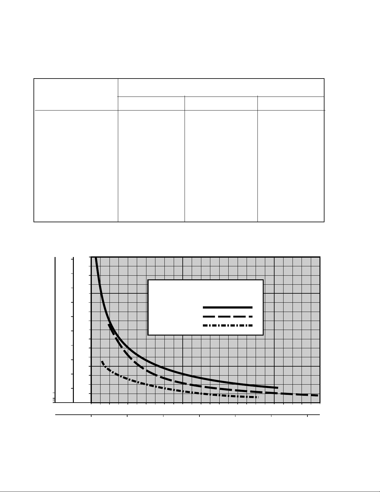
4.11 CUTTING SPEEDS (continued)
Material Thickness Inches per Minute (Meters per Minute)
50 Amps 100 Amps 150 Amps
1/8 130 (3.30) 225 (5.7)
3/16
1/4 65 (1.65) 100 (2.54) 160 (4.06)
3/8 28 (.71) 100 (2.54)
1/2 16 (.41) 58 (1.47) 80 (2.03)
3/4 32 (0.81) 35 (0.89)
1 22 (0.56) 28 (0.71)
1-1/2 12 (0.30)
2 5 (0.13)
Table 4-F Cutting Speeds - Oxygen Plasma on Mild Steel, CO
Gage MM Inches
2.00
50
45
1.75
40
1.50
35
1.25
30
1.00
25
20
.75
MATERIAL THICKNESS
Inches per Minute
10
16
24
15
10
.50
.25
5
050
Optimum Cutting Speeds
Oxygen Plasma
on Mild Steel
150 Amps
100 Amps
50 Amps
100 150 200
Secondary
2
A-00883
250
Meters per Minute
1.0 2.0
3.0 4.0 5.0 6.00
CUTTING SPEED
Figure 4-O Cutting Speeds - Oxygen Plasma on Mild Steel
OPERA TION 56 Manual 0-2251
Page 61

4.11 CUTTING SPEEDS (continued)
Material Thickness Inches per Minute (Meters per Minute)
50 Amps 100 Amps 150 Amps
1/8 100 (2.54)
1/4 40 (1.02) 140 (3.56) 175 (4.45)
5/16 30 (0.76)
3/8 9 (0.23) 75 (1.90) 110 (2.79)
1/2 60 (1.52) 85 (2.16)
3/4 40 (1.02)
1 25 (0.64)
1-1/2 12 (0.30)
2
Table 4-G Cutting Speeds - Nitrogen Plasma on Stainless Steel
Gage MM Inches
2.00
50
45
1.75
40
1.50
35
1.25
30
1.00
25
20
.75
MATERIAL THICKNESS
Inches per Minute
10
16
24
15
10
.50
.25
5
050
Optimum Cutting Speeds
Nitrogen Plasma - CO2 Secondary
on Stainless Steel
150 Amps
100 Amps
50 Amps
100 150 200
A-00882
250
Meters per Minute
1.0 2.0
3.0 4.0 5.0 6.00
CUTTING SPEED
Figure 4-P Cutting Speeds - Nitrogen Plasma on Stainless Steel
Manual 0-2251 57 OPERA TION
Page 62

4.11 CUTTING SPEEDS (continued)
Material Thickness Inches per Minute (Meters per Minute)
50 Amps 100 Amps 150 Amps
1/8
1/4
5/16
3/8
1/2 35 (0.89)
3/4 27 (0.69)
1 20 (0.51)
1-1/2 10 (0.25)
2
Table 4-H Cutting Speeds - Argon/Hydrogen Plasma on Stainless Steel
Gage MM Inches
2.00
50
45
1.75
40
1.50
35
1.25
30
1.00
25
20
.75
MATERIAL THICKNESS
Inches per Minute
10
16
24
15
10
.50
.25
5
050
Optimum Cutting Speeds
Ar/H2 Plasma - N2 Secondary
on Stainless Steel
150 Amps
100 150 200
A-00886
250
Meters per Minute
1.0 2.0
3.0 4.0 5.0 6.00
CUTTING SPEED
Figure 4-Q Cutting Speeds - Argon/Hydrogen Plasma on Stainless Steel
OPERA TION 58 Manual 0-2251
Page 63
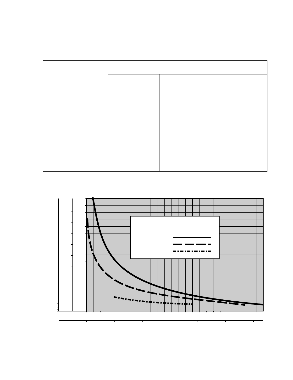
4.11 CUTTING SPEEDS (continued)
Material Thickness Inches per Minute (Meters per Minute)
50 Amps 100 Amps 150 Amps
1/8 150 (3.81) 225 (5.72) 275 (6.99)
1/4 40 (1.02) 135 (3.43) 150 (3.81)
5/16
3/8
1/2 60 (1.52) 95 (2.41)
3/4 18 (0.46) 52 (1.32)
1 15 (0.38) 36 (0.91)
1-1/2 18 (.46)
2
Gage MM Inches
2.00
50
45
1.75
40
1.50
35
1.25
30
1.00
25
20
.75
MATERIAL THICKNESS
Inches per Minute
10
16
24
15
10
.50
.25
5
Table 4-I Cutting Speeds - Air Plasma on Aluminum
Optimum Cutting Speeds
Air Plasma - Air Secondary
on Aluminum
150 Amps
100 Amps
50 Amps
050
100 150 200
A-00884
250
Meters per Minute
1.0 2.0
3.0 4.0 5.0 6.00
CUTTING SPEED
Figure 4-R Cutting Speeds - Air Plasma on Aluminum
Manual 0-2251 59 OPERA TION
Page 64

4.11 CUTTING SPEEDS (continued)
Material Thickness Inches per Minute (Meters per Minute)
50 Amps 100 Amps 150 Amps
1/8
1/4 100 (2.54)
5/16
3/8
1/2 75 (1.90)
3/4 60 (1.52)
1 35 (0.89)
1-1/2 21 (0.53)
2
Table 4-J Cutting Speeds - ArH
Gage MM Inches
2.00
50
45
1.75
40
1.50
35
1.25
30
1.00
25
20
.75
MATERIAL THICKNESS
Inches per Minute
10
16
24
15
10
.50
.25
5
050
2 Plasma/Nitrogen Secondary on Aluminum
Optimum Cutting Speeds
ArH2 Plasma - N2 Secondary
on Aluminum
150 Amps
100 Amps
50 Amps
100 150 200
A-00885
250
Meters per Minute
1.0 2.0
3.0 4.0 5.0 6.00
CUTTING SPEED
Figure 4-S Cutting Speeds - ArH2 Plasma/Nitrogen Secondary on Aluminum
OPERA TION 60 Manual 0-2251
Page 65

4.12 SEQUENCE OF OPERATION
ACTION
Close external
disconnect switch
RESULT
• Power to system
ACTION
Protect eyes and
activate torch
RESULT
• Gas indicator ON
• Gas pre-flow
• Main contactor
closes
• DC indicator ON
• Pilot contactor
closes
• PILOT indicator ON
• Pilot arc established
ACTION
Enable ON at Remote
or TB2
ON/OFF switch to ON
RESULT
• AC indicator ON
• TEMP Indicator ON
• GAS indicator ON
• Fan and pump ON
• 40 second auto-purge
PILOT ARC
ACTION
RUN/SET/PURGE
switch to SET
RESULT
• Gas solenoids open,
gases flow to set
pressures
• GAS indicator ON
ACTION
RUN/SET/PURGE
switch to RUN
RESULT
• Gas flow stops
• Power circuit ready
• GAS indicator OFF
ACTION
Torch removed from
work
RESULT
• Main arc stops
• Pilot arc auto-restart
• PILOT indicator ON
ACTION
Torch moved to
within
1/8 - 3/8 inch of
work
ACTION
Torch de-activated by torch switch
released or remote device
RESULT
• Main arc stops
• Main contactor opens
• DC indicator OFF
• Pilot and PILOT indicator OFF
NOTE- If torch is activated during post-flow
the pilot arc will immediately restart. If
within range of work, main arc will transfer.
After post-flow:
• Gas solenoids close, gas flow stops
• GAS indicator OFF
ACTION
ON/OFF switch to
OFF
RESULT
• AC indicator OFF
• TEMP Indicator OFF
• Fan and pump OFF
RESULT
• Main arc transfer
• PILOT indicator OFF
• Pilot arc OFF
ACTION
Open external
disconnect
RESULT
• No power to system
A-01016
Figure 4-T Sequence of Operation
Manual 0-2251 61 OPERA TION
Page 66

OPERA TION 62 Manual 0-2251
Page 67

SECTION 5: CUSTOMER/OPERATOR SERVICE
5.1 TORCH MAINTENANCE
WARNING
Routine Inspection
and Replacement of
Consumable Parts:
NOTE
Disconnect primary power to the system before
disassembling the torch, leads, or power supply.
Refer to Figure 5-A and:
1. Remove the shield cup (1) from the torch body (6 or 7).
2. Unscrew the tip (2) using the tip wrench (9). Check for
tip wear (indicated by elongated or oversize orifice).
Clean the tip and make sure the threads and sealing face
are not damaged. Replace tip if necessary.
3. Remove the electrode (3) using the electrode wrench
(10). Inspect the condition of the face of the electrode
(see CAUTION below).
Check the torch for proper assembly. Make sure both the
tip and electrode in the torch correspond with the plasma
gas and secondary being used. (See Section 4.3, Torch Parts
Selection).
14
9
1. Machine Torch Body
2. 70° Hand Torch Body
3. O-Ring (Handle)
4. O-Ring (Cup - Lg.)
5. O-ring (Cup - Sm.)
6. Air Electrode
7. Oxygen Electrode
8. Multi-Gas Electrode
9. Air Tip
10. Oxygen Tip
1
6
7
2
3
11. Nitrogen Tip
12. Ar/H
13. Gouging Tip
14. Standard Shield Cup
15. Copper Shield Cup
16. Touch Cup
17. Gouging Cup
18. Tip Wrench
19. Electrode Wrench
2 Tip
45
8
Figure 5-A PCH/M-150 Torch Components
10
11
12
13
18
19
15
16
17
Manual 0-2251 63 CUSTOMER/OPERATOR SER VICE
Page 68

5.1 TORCH MAINTENANCE (continued)
NOTE
CAUTION
If face of electrode is pitted or gouged more than 3/32 in
(2.4 mm) deep, the electrode should be replaced (see
Figure 5-B).
4. Replace the electrode in the torch body. Secure in place
using the electrode wrench.
5. Replace the tip in the front of the torch and secure it
with the tip wrench.
Do not overtighten the electrode or tip.
6. Inspect the shield cup for damage. Wipe it clean, or
replace if it appears to be damaged.
7. Re-install the shield cup. Apply a light coat of O-ring
lubricant to the shield cup O-rings (4,5). Use a slight
twisting motion to seat the cup properly on the O-rings
and against the torch face.
Look for extreme
pitted or blown out
appearance
3/32 in
Figure 5-B Electrode Deterioration
5.2 HAND TORCH HEAD REPLACEMENT
WARNING
Hand Torch Head
Replacement
Disconnect primary power to the system before
disassembling the torch, leads, or power supply.
Refer to Figure 5-C and:
1. Roll the torch switch sheath up over the handle to
expose the two torch switch connectors.
2. Remove the tape from the end of the leads sleeving and
pull the sleeving back approximately one foot (0.3 m).
3. Remove the tape from the two single-pin torch switch
connectors and disconnect the torch switch leads.
Worn ElectrodeNew Electrode
CUSTOMER/OPERATOR SERVICE 64 Manual 0-2251
Page 69

5.2 HAND TORCH HEAD REPLACEMENT (continued)
Hand Torch Head
Replacement (continued)
NOTE
CAUTION
4. With a twisting motion, pull the handle from the torch
head. Slide the handle back over the leads to expose the
leads connections.
5. Remove the tape that secures the lead connections
around the insulating tab. Disconnect the plasma,
secondary, coolant supply, and coolant return leads
from the torch head.
To minimize coolant leaks during torch head replacement,
perform the operation with the torch head above the level
of the coolant reservoir.
6. Connect the plasma, secondary, coolant supply, and
coolant return leads onto the replacement torch head
fittings.
7. Use electrical tape to secure the leads in place on the
insulating tab. Locate the tape over the ferrule on the
negative lead.
Make sure the insulating tab completely separates the
coolant supply lead (negative) from the plasma, secondary,
and coolant return leads.
8. Replace the handle onto the torch head.
9. Connect the two torch switch leads connectors and
secure the torch switch leads in place with electrical
tape.
10. Secure the leads sleeving to the leads with electrical
tape. Position the tape close to the back of the handle.
11. Roll the torch switch sheath back over the handle.
Figure 5-C Hand Torch Head Replacement
Manual 0-2251 65 CUSTOMER/OPERATOR SER VICE
Page 70

5.3 MACHINE TORCH HEAD REPLACEMENT
WARNING
Machine Torch Leads
Replacement
NOTE
Disconnect primary power to the system before
disassembling the torch, leads, or power supply.
Refer to Figure 5-D and:
1. Remove the electrical tape from the end of the nylon
outer leads sleeving next to the mounting assembly
and push the sleeving back onto the leads approximately one foot (0.3 m) to expose the shielded inner
leads sleeving.
2. Remove the electrical tape from the shielded inner
sleeving and push back over the leads approximately
one foot (0.3 m).
3. Unscrew the mounting assembly from the torch head.
Slide the mounting assembly back over the leads to
expose the leads connections.
4. Remove the tape that secures the lead connections
around the insulating tab. Disconnect the plasma,
secondary, coolant supply, and coolant return leads
from the torch head.
To minimize coolant leaks during torch head replacement,
perform the operation with the torch head above the level
of the coolant reservoir.
5. Connect the plasma, secondary, coolant supply, and
coolant return leads onto the replacement torch head
fittings.
6. Use electrical tape to secure the leads in place on the
insulating tab. Locate the tape over the ferrule on the
negative lead.
CUSTOMER/OPERATOR SERVICE 66 Manual 0-2251
Page 71

5.3 MACHINE TORCH HEAD REPLACEMENT (continued)
Torch Head
CAUTION
Electrical
Tape
Make sure the insulating tab completely separates the
coolant supply lead (negative) from the plasma, secondary,
and coolant return leads.
7. Replace the mounting assembly onto the torch head.
8. Secure the shielded inner sleeving to the leads with
electrical tape. Position the end of the sleeving a few
inches back from the mounting assembly.
9. Position the nylon outer sleeving over the shielded
inner sleeving. The shielded inner sleeving must be
completely covered by the outer sleeving to avoid any
possible contact with the mounting assembly.
10. Secure the nylon outer leads sleeving to the leads with
electrical tape. Position the tape close to the back of the
mounting assembly.
Coolant Return
Lead
Plasma
Lead
Mounting
Assembly
Shielded Inner
Leads Sleeving
Electrical
Tape
A-00961
Insulating T ape
Secondary
Lead
Coolant Supply
Lead
Nylon Outer
Leads Sleeving
Figure 5-D Machine Torch Head Replacement
Manual 0-2251 67 CUSTOMER/OPERATOR SER VICE
Page 72

5.4 HAND TORCH SWITCH REPLACEMENT
WARNING
Hand Torch Head
Replacement
Disconnect primary power to the system before
disassembling the torch, leads, or power supply.
Refer to Figure 5-C and:
1. Roll the sheath up over the torch handle to expose the
torch switch connectors and the torch switch.
2. Remove the tape from the two single-pin torch switch
connectors and disconnect the torch switch leads.
3. Replace the torch switch and connect the two torch
switch leads connectors.
4. Secure the torch switch leads in place with electrical
tape. Locate the tape over the two connectors.
5. Roll the torch switch sheath back over the handle to
cover the torch switch and connectors.
CUSTOMER/OPERATOR SERVICE 68 Manual 0-2251
Page 73

5.5 HAND TORCH LEADS REPLACEMENT
WARNING
Hand Torch Leads
Replacement
Disconnect primary power to the system before
disassembling the torch, leads, or power supply.
Refer to Figure 5-C and:
1. Roll the torch switch sheath up over the handle to
expose the two torch switch connectors.
2. Remove the tape from the end of the leads sleeving
and pull the sleeving back approximately one foot (0.3
m).
3. Remove the tape from the two single-pin torch switch
connectors and disconnect the torch switch leads.
4. With a twisting motion, pull the handle from the torch
head. Slide the handle back over the leads to expose
the leads connections.
5. Remove the tape that secures the lead connections
around the insulating tab. Disconnect the plasma,
secondary, coolant supply, and coolant return leads
from the torch head.
(continued)
Control Cable
(Hand T orch Only)
Plasma Lead
Secondary Lead
Shielded Inner Leads Sleeving
(Machine T orch Only)
Torch Leads Shield Assembly
Nylon Outer Leads Sleeving
Coolant Supply Lead
Hose Clamp
Torch Leads Boot
Coolant Return Lead
A-00903
Figure 5-E Leads Connections at the Power Supply
Manual 0-2251 69 CUSTOMER/OPERATOR SER VICE
Page 74

5.5 HAND TORCH LEADS REPLACEMENT (continued)
NOTE
CAUTION
To minimize coolant leaks during torch head replacement,
perform the operation with the torch head above the level
of the coolant reservoir.
6. Position the replacement leads and connect the plasma,
secondary, coolant supply, and coolant return leads
onto the torch head fittings.
7. Use electrical tape to secure the leads in place on the
insulating tab. Locate the tape over the ferrule on the
negative lead.
Make sure the insulating tab completely separates the
coolant supply lead (negative) from the plasma, secondary,
and coolant return leads.
8. Replace the handle onto the torch head.
9. Connect the two torch switch leads connectors. Secure
the torch switch leads in place with electrical tape.
10. Secure the leads sleeving to the leads with electrical
tape. Position the tape close to the back of the handle.
11. Roll the torch switch sheath back over the handle.
Refer to Figure 5-E and:
12. Open the leads connection access door on the power
supply. Disconnect the plasma, secondary, coolant
supply and coolant return leads and the control cable
plug from the bulkhead.
13. Position the replacement leads. Feed the control cable
plug through the torch leads boot first and connect to
the bulkhead. Then feed the other leads through the
torch leads boot and connect the plasma, secondary,
coolant supply and coolant return leads to the bulkhead.
CUSTOMER/OPERATOR SERVICE 70 Manual 0-2251
Page 75

5.6 MACHINE TORCH LEADS REPLACEMENT
WARNING
Machine Torch Leads
Replacement
Disconnect primary power to the system before
disassembling the torch, leads, or power supply.
Refer to Figure 5-D and:
1. Remove the electrical tape from the end of the nylon
outer leads sleeving next to the mounting assembly.
2. Push the nylon outer sleeving back up the leads approximately one foot (0.3 m) to expose the shielded
inner leads sleeving.
3. Remove the electrical tape from the shielded inner
sleeving and push back up the leads approximately
one foot (0.3 m).
4. Unscrew the mounting assembly from the torch head.
Slide the mounting assembly back over the leads to
expose the leads connections.
5. Remove the tape that secures the lead connections
around the insulating tab. Disconnect the plasma,
secondary, coolant supply, and coolant return leads
from the torch head.
NOTE
CAUTION
To minimize coolant leaks during torch head replacement,
perform the operation with the torch head above the level
of the coolant reservoir.
6. Connect the plasma, secondary, coolant supply, and
coolant return leads onto the replacement torch head
fittings.
7. Use electrical tape to secure the leads in place on the
insulating tab. Locate the tape over the ferrule on the
negative lead.
Make sure the insulating tab completely separates the
coolant supply lead (negative) from the plasma, secondary,
and coolant return leads.
8. Replace the mounting assembly onto the torch head.
9. Secure the shielded inner sleeving to the leads with
electrical tape. Position the end of the sleeving a few
inches back from the mounting assembly.
Manual 0-2251 71 CUSTOMER/OPERATOR SER VICE
Page 76

5.6 MACHINE TORCH LEADS REPLACEMENT (continued)
Machine Torch Leads
Replacement (continued)
Power Supply Connections
10. Position the nylon outer sleeving over the shielded
inner sleeving. The shielded inner sleeving must be
completely covered by the outer sleeving to avoid any
possible contact with the mounting assembly.
11. Secure the nylon outer leads sleeving to the leads with
electrical tape. Position the tape close to the back of the
mounting assembly.
Refer to Figure 5-E and:
12. Open the leads connection access door on the power
supply. Remove the hose clamp that secures the
shielded inner leads sleeving to the brass grounding
tube.
13. Disconnect the plasma, secondary, coolant supply and
coolant return leads from the bulkhead.
14. Position the replacement leads and connect the plasma,
secondary, coolant supply and coolant return leads to
the bulkhead.
15. Attach the shielded inner leads sleeving to the brass
grounding tube and secure with hose clamp. The
shielded inner sleeving must not contact any torch
fittings, ferrules, or connections.
CUSTOMER/OPERATOR SERVICE 72 Manual 0-2251
Page 77

5.7 LEADS EXTENSION KITS - HAND TORCH
Leads extension packages are available in 25 ft (7.6 m) or
50 ft (15.2 m) lengths. Leads can be extended up to a
maximum of 150 ft (45.8 m).
Leads extension kits for hand torch systems include:
• Plasma, Secondary, Coolant Supply and Coolant Return
Leads Extensions in 25 or 50 ft (7.6 or 15.2 m) lengths
• Control Cable Extension - 25 or 50 ft (7.6 or 15.2 m)
• Nylon Outer Sleeving - 25 or 50 ft (7.6 or 15.2 m)
• Coolant Supply Lead Insulator
• Plasma Lead Insulator
• (2) Union Fittings
WARNING
Disconnect Existing Leads
NOTE
Connect Leads Extension
to Power Supply
Connect Coolant Supply
Lead to Extension Package
Disconnect primary power to the system before
disassembling the torch, leads, or power supply.
Refer to Figure 5-E and:
1. Disconnect the plasma lead, secondary lead, coolant
supply lead, coolant return lead, and the control cable
plug from the bulkhead.
To minimize coolant leaking from the leads during installation, keep the leads connections above the level of the
torch head and existing leads.
2. Position the extension kit and connect the plasma,
secondary, coolant supply, coolant return leads extensions and the control cable extension to the bulkhead.
Refer to Figure 5-F and:
3. Slide the coolant supply insulator over the coolant
supply lead on the existing torch leads.
4. Push the coolant supply lead on the existing leads into
the union fitting as far as possible.
5. Connect the coolant supply lead from the torch leads
through the union fitting to the coolant supply lead
from the extension kit and tighten securely.
6. Thread the coolant supply insulator on the existing
torch leads onto the union fitting and tighten securely.
(continued)
Manual 0-2251 73 CUSTOMER/OPERATOR SER VICE
Page 78

5.7 LEADS EXTENSION KITS - HAND TORCH (continued)
7. Thread the coolant supply insulator on the leads
extension into the union fitting and tighten securely.
8. Slide the plasma insulator over the plasma lead on the
existing torch leads.
9. Push the plasma lead on the existing leads into the
union fitting as far as possible.
Connect Plasma Lead to
Extension Package
Connect Coolant Return,
Secondary, and Control
Cable to Extension Package
Electrical
Tape
From
Power Supply
(Extension Kit)
Plasma
Lead
10. Connect the plasma lead from the torch leads, through
11. Thread the plasma insulator on the existing torch leads
12. Thread the plasma insulator on the leads extension into
13. Connect the secondary and coolant return leads to the
14. Connect the control cable plug to the receptacle on the
Coolant Supply
Lead
the union, to the plasma lead from the extension kit
and tighten securely.
onto the union fitting and tighten securely.
the union fitting and tighten securely.
extension kit fittings.
leads extension package.
Coolant Supply
Union
Fitting
Insulator
Plasma
Insulator
Electrical
Tape
T o Torch
(Existing Leads)
Secondary
Lead
Coolant Return
Lead
Control Cable
(Hand T orch Only)
A-00962
Figure 5-F Hand Torch Leads Extension Package
CUSTOMER/OPERATOR SERVICE 74 Manual 0-2251
Page 79

5.8 LEADS EXTENSION KITS - MACHINE TORCH
Leads extension packages are available in 25 ft (7.6 m) or
50 ft (15.2 m) lengths. Leads can be extended up to a
maximum of 150 ft (45.8 m).
Leads extension kits for machine torch systems include:
• Plasma, Secondary, Coolant Supply and Coolant Return
Leads Extensions in 25 or 50 ft (7.6 or 15.2 m) lengths
• Shielded Inner Sleeving - 25 or 50 ft (7.6 or 15.2 m)
• Nylon Outer Sleeving - 25 or 50 ft (7.6 or 15.2 m)
• Shielded Inner Sleeving Connector - 12 in (0.30 m)
• Nylon Outer Sleeving Connector - 24 in (0.61 m)
• (2) Hose Clamps
• Coolant Supply Lead Insulator
• Plasma Lead Insulator
• (2) Union Fittings
WARNING
Disconnect Existing Leads
NOTE
Connect Leads Extension
to Power Supply
Disconnect primary power to the system before
disassembling the torch, leads, or power supply.
Refer to Figure 5-E and:
1. Remove the hose clamp from the torch leads shield
assembly inside the leads access area to release the
shielded inner sleeving.
2. Disconnect the plasma and secondary leads and
coolant supply and return leads from the bulkhead.
To minimize coolant leaks from the leads during installation, keep the leads connections above the level of the
torch head and existing leads.
3. Position the extension kit and connect the plasma,
secondary, coolant supply, and coolant return leads
extensions to the bulkhead.
4. Connect the shielded inner sleeving to the torch leads
shield assembly and secure with the hose clamp.
(continued)
Manual 0-2251 75 CUSTOMER/OPERATOR SER VICE
Page 80

5.8 LEADS EXTENSION KITS - MACHINE TORCH (continued)
Connect Existing Leads to
Leads Extension
Connect Coolant Supply
Lead to Extension Package
Refer to Figure 5-G and:
5. Slide the 24-inch nylon outer sleeving connector over
the existing leads before making connections. The
connector will later be pulled down to cover all connections.
6. Remove the shrink-on tubing and tape that secures the
end of the nylon outer sleeving to the existing leads.
7. At the end of the existing leads, all four individual
leads are enclosed by the shielded inner sleeving. Pull
the nylon outer sleeving back approximately 12 in (0.3
m) to expose the area where the coolant return and
secondary leads are run through from the outside to
the inside of the shielded inner sleeving.
8. Pull the secondary and coolant return leads out
through the shielded inner sleeving (only the coolant
supply and plasma leads remain inside the sleeving).
9. Slide the 12-inch shielded inner sleeving connector
over the coolant supply and plasma leads of the extension kit.
Refer to Figure 5-F and:
10. Slide the coolant supply insulator over the coolant
supply lead on the existing torch leads.
Connect Plasma Lead to
Extension Package
11. Push the coolant supply lead on the existing leads into
the union fitting as far as possible.
12. Connect the coolant supply lead from the torch leads
through the union fitting to the coolant supply lead
from the extension kit and tighten securely.
13. Thread the coolant supply insulator on the existing
torch leads onto the union fitting and tighten securely.
14. Thread the coolant supply insulator on the leads
extension into the union fitting and tighten securely.
15. Slide the plasma insulator over the plasma lead on the
existing torch leads.
16. Push the plasma lead on the existing leads into the
union fitting as far as possible.
17. Connect the plasma lead from the existing torch leads
through the union fitting to the plasma lead from the
extension kit and tighten securely.
18. Thread the plasma insulator on the existing torch leads
onto the union fitting and tighten securely.
CUSTOMER/OPERATOR SERVICE 76 Manual 0-2251
Page 81

5.8 LEADS EXTENSION KITS - MACHINE TORCH (continued)
19. Thread the plasma insulator on the leads extension into
the union fitting and tighten securely.
Refer to Figure 5-G and:
20. Pull each end of the shielded inner sleeving (from the
existing leads and from the leads extension) up and
over the plasma and coolant supply insulators. Position the 12-inch shielded inner sleeving connector
down over the completed coolant supply and plasma
connections. Secure the connector in place with a hose
clamp on each end.
NOTE
Connect Coolant Return and
Secondary to
Extension Package
Electrical
Tape
From
Power Supply
(Extension Kit)
Locate Clamp
Over Insulators
Locate the hose clamps over the plasma and coolant
supply insulators to provide a solid connection. The
shielding must be continuous throughout the connection
(from the extension kit, through the connector, to the
original leads) to ensure proper shielding protection.
21. Connect the secondary and coolant return leads to the
extension kit fittings.
22. Slide the 24-inch nylon sleeving connector down to
cover all connections. Secure with electrical tape.
Coolant Supply
Plasma
Lead
Lead
12" Shielded
Inner Sleeving
Electrical
Tape
T o Torch
(Existing Leads)
Secondary
Lead
From
Power Supply
(Extension Kit)
24" Nylon Outer Sleeving
Coolant Return
Lead
Locate Clamp
Over Insulators
T o Torch
(Existing Leads)
A-00963
Figure 5-G Machine Torch Leads Extension
Manual 0-2251 77 CUSTOMER/OPERATOR SER VICE
Page 82

5.9 POWER SUPPLY MAINTENANCE
Fan Motor and Pump
Lubrication
NOTE
Routine Maintenance
The fan motor and pump in the power supply should be
oiled twice per year or once for each 100 hours of operation. To oil the motor, remove one side panel and add two
or three drops of 20 SAE oil to the front and rear oil holes
on the motor.
Some units may utilize a sealed motor design which does
not require lubrication.
The only other routine maintenance required for the power
supply is a thorough cleaning and inspection, with the
frequency depending on the usage and the operating
environment.
To clean the unit, first make sure that the power is disconnected. Remove the side panels and blow out any accumulated dirt and dust with compressed air. The unit should
also be wiped clean. If necessary, solvents that are recommended for cleaning electrical apparatus may be used.
While the side panels are off, inspect the wiring in the unit.
Look for any frayed wires or loose connections that should
be corrected. When cleaning the unit, inspect the area
around the high frequency spark gap points. Accumulated
dirt in the area around the spark gap assembly can weaken
the high frequency starting and cause poor pilot starting.
CUSTOMER/OPERATOR SERVICE 78 Manual 0-2251
Page 83

5.10 TROUBLESHOOTING THEORY
Input Voltage Selection
Switch-Mode Power
Supply Operation
The main transformer (T1) has buss bar connections to
select one of three input voltage ranges (see page 2-6).
Each main transformer secondary has two taps. One
secondary tap is automatically selected by the voltage
selection PC board when primary power is applied. If
input voltage is within the lower half of the selected
voltage range (for example, 380V or 415V in the 380/415/
460V range), the higher voltage taps are selected. If input
voltage is within the upper half of the selected voltage
range (460 V in the 380/415/460V range), the lower voltage taps are selected. This arrangement provides secondary voltages close to the optimum levels. When the lower
voltage taps are selected a red LED indicator (D18) on the
voltage selection PC board will be lit.
The 115 VAC and lower voltage taps are selected directly
by relays on the voltage selection PC board. The fan and
pump motors are supplied by the motor control contactors
(MC1 and MC2). MC1 is for the high voltage tap and MC2
is for the low voltage tap. Three-phase primary power is
controlled by one of the main contactors (W1 for the high
voltage tap or W2 for the low voltage tap).
Primary three-phase power is rectified by diodes D1-D6.
The resulting negative DC voltage (approximately -320
VDC) is applied to the switching transistor (Q1). The
switching transistor controls the output current by pulse
width modulation (PWM). PWM varies the duty cycle (or
on-time versus off-time) of the switch. The greater the ontime, the higher the output current will be. The switching
transistor output is a series of pulses which are filtered
back into pure DC voltage by the output network. The
output network consists primarily of the main inductor
(L2A and L2B), resistor R13, and capacitor C23.
The switching control PC board compares the shunt amp
output with the current control pot setting and generates
logic level PWM signals. The shunt and shunt amp PC
board are located between the positive bridge and work
lead to measure the output cutting current. The signals are
sent to the driver PC board, where they are converted into
the current and voltage levels needed to drive the switching transistor.
Switching Control Board
Manual 0-2251 79 CUSTOMER/OPERATOR SER VICE
The switching control PC board senses if the remote
control panel is connected by a jumper in the remote cable.
If the remote cable is not used, a relay on the switching
control PC board shorts J15-35 to J15-36. The short by-
(continued)
Page 84

5.10 TROUBLESHOOTING THEORY (continued)
Switching Control Board
(continued)
Logic Board Functions
passes the E-Stop function of the remote. The switching
control PC board also routes the shunt amp output to the
digital ammeter in the remote. CSR (current greater than
25A) and over-current shutdown (greater than 175A)
signals are sent to the logic PC board.
The logic PC board controls the timing and sequencing of
the system. It monitors the pressure, temperature, and
flow interlocks and controls the gas flow in run, set, and
purge modes by turning on the plasma and secondary
solenoids. The logic PC board also controls pre-flow and
post-flow durations, which are selectable by DIP switches
on the board (see Figure 4-G). The logic board drives the
sequence status LED indicators and contains the circuit for
measuring coolant conductivity.
The logic board receives either a latched start signal from
the remote control panel or a non-latching start signal from
the hand torch switch or remote pendant. Both latching
and non-latching signals are available from CNC devices.
The logic PC board then initiates gas pre-flow and energizes the main contactor W1 or W2 (as directed by the
voltage selection PC board). The logic board then enables
the PWM switching control circuit. The logic board immediately activates the pilot contactor to initiate the pilot arc.
As soon as the pilot arc (constant DC current) is established, the PSR relay shuts off the high frequency. The
logic board supplies ‘OK-to-move’ contacts, which close
when main arc transfer has occurred and pilot has shut off.
A second ‘OK-to-move’ contact is wired to control an
optional high-flow water shield.
LED/Current Control Board
Remote Control
CUSTOMER/OPERATOR SERVICE 80 Manual 0-2251
The LED and current control PC board contains the
sequence status LED indicators and the front panel current
control pot.
The remote control unit contains the several system control
functions. Momentary start and stop switches control
system operation and the main current control pot controls
cutting current output. A digital ammeter displays a
preview of the main current setting (or corner slowdown
setting) before starting the cut and displays actual cutting
current after arc transfer. A behind-the-panel control sets
corner slowdown current reduction and an emergency
stop switch shuts off the power supply's main contactors,
gases, and coolant system. CNC interface connectors and
the power supply remote cable connection are located on
the rear panel of the remote.
Page 85

5.10 TROUBLESHOOTING THEORY (continued)
Figure 5-H Major System Components - Front View
Manual 0-2251 81 CUSTOMER/OPERATOR SER VICE
Page 86

5.10 TROUBLESHOOTING THEORY (continued)
Figure 5-I Major System Components - Rear View
CUSTOMER/OPERATOR SERVICE 82 Manual 0-2251
Page 87

5.11 TROUBLESHOO TING GUIDE
SYMPTOM POSSIBLE CAUSE REMEDY
A. No front panel LED
indicators lit. Fan and
pump off.
B. AC indicator on. Fan and
pump off.
1. No primary power. See
also Symptoms C and D
2. Blown fuse (F2)
3. Faulty ON/OFF switch
(SW1)
4. Faulty voltage selection
board
1. No primary power See
also Symptoms C and D
2. Blown fuse (F1 or F2)
3. Faulty ON/OFF switch
(SW1)
4. Faulty voltage selection
board
1. Check for proper threephase power at input
terminal board
2. Check and replace fuse if
necessary
3. Disconnect primary
power. Check each section
for continuity. Replace
switch if necessary
4. See Sction 5.12-Test A and
replace board if necessary
1. Check for proper threephase power at input
terminal board
2. Check and replace fuse if
necessary. See Section
5.12-Test B
3. Disconnect primary
power. Check each section
for continuity. Replace
switch if necessary
4. See Section 5.12-Test A
and replace board if
necessary
5. Faulty motor contactor
(MC1 or MC2)
(Causes 6 and 7 are only
for systems having remote control panel)
Manual 0-2251 83 CUSTOMER/OPERATOR SER VICE
6. Faulty switching control
board (relay K1 not
energized to bypass
remote E-stop function)
7. Remote cable plugged into
J15; remote control panel
not connected on other
end of cable
8. Remote panel E-stop
button activated (or
faulty)
5. See Section 5.12-Test C
and replace contactor if
necessary
6. See Section 5.12-Test C,
Step 3
7. Remove cable plug from
J15 or connect remote
panel correctly
8. Twist button clockwise to
release. If necessary, check
for continuity from J37-35
to J37-36
(continued)
Page 88

5.11 TROUBLESHOOTING GUIDE (continued)
SYMPTOM POSSIBLE CAUSE REMEDY
C. Fuse blown at disconnect
when primary power is
connected
D. Fuse blown at disconnect
when main contactor (W1
or W2) closes
1. Voltage selection bus bars
connected incorrectly
2. One leg of three-phase
primary connected to
chassis ground
3. Main transformer shorted
1. Shorted input diode
(D1-D6)
2. Switching transistor (Q1)
shorted to heatsink
3. Shorted input capacitor
(C7-C12)
4. Shorted diode (D11-D14)
5. Faulty voltage selection
board
1. Check and correct if
necessary.
2. Rewire input cable (see
Section 3.4, Electrical
Connections)
3. Replace main transformer
1. See Section 5.12-Test D
and replace diode if
necessary
2. Replace Q1, check heatsink for possible damage
(see Section 5.12-Test D)
3. Replace capacitor if
necessary
4. Check for proper 3-phase
power at input terminal
board, check diodes (see
Section 5.12-Test D)
5. If W1 and W2 come on
simultaneously replace
board.
E. TEMP indicator lit (red).
F. No GAS indicator
6. Faulty main contactor (W1
or W2)
1. Unit overheated
2. Faulty thermal sensor
(TS1, TS2, or TS3)
3. Faulty logic board
4. Faulty LED/current
control board
1. RUN/SET/PURGE switch
set to PURGE, secondary
mode switch set to GAS
secondary
2. Gas pressure set too low
6. Check and replace contactor if necessary
1. Clean radiator and check
for obstruction.
2. See Section 5.12-Test E
and replace sensors if
necessary
3. See Section 5.12-Test E
and replace board if
necessary
4. See Section 5.12-Test E
and replace board if
necessary
1. Normal operation (purges
plasma line only, secondary flow switch is not
satisfied)
2. Adjust pressure
CUSTOMER/OPERATOR SERVICE 84 Manual 0-2251
Page 89

5.11 TROUBLESHOOTING GUIDE (continued)
SYMPTOM POSSIBLE CAUSE REMEDY
F. No GAS indicator
(continued)
G. GAS indicator off, plasma
and/or secondary gas
does not flow
3. Faulty pressure switch
(PS1 or PS2)
4. Faulty logic board
5. Faulty LED/current
control board
6. Faulty SW3-B (secondary
mode set to O
2 or H2O )
1. RUN/SET/PURGE switch
set to PURGE, secondary
mode switch set to GAS
secondary
2. Secondary mode set to O
2
3. Jump switches one at a
time and check for indicator to determine which
has failed. Replace switch
if necessary
4. See Section 5.12-Test F
and replace board if
necessary
5. See Section 5.12-Test F
and replace board if
necessary
6. With secondary mode set
to O
2 or H2O, check for
continuity from wire #52
to #55 on SW3-B. If open,
replace SW3-B
1. Normal operation (purges
plasma line only, secondary does not flow)
2. No secondary flow is
normal operation in O
2
mode (but GAS indicator
should be lit)
3. Low plasma pressure or
faulty PS1
3. Check plasma pressure,
check PS1 and replace if
necessary
4. Secondary supply turned
4. Check secondary supply
off (or tank empty)
5. Faulty solenoid valve:
SOL1 - plasma gas,
SOL2 - secondary gas,
SOL3 - secondary water
6. Faulty switch (SW3-A)
(effects sec. gas or water
only, not secondary O
2)
5. Check solenoid for sticking or clogging. Check coil
resistance (should be
approx. 400 ohms)
6. Check SW3-A for continuity (wire 75 to 88 for
secondary gas, 75 to 89 for
secondary water)
7. Faulty logic board
7. See Section 5.12-Test G
and replace board if
necessary
(continued)
Manual 0-2251 85 CUSTOMER/OPERATOR SER VICE
Page 90

5.11 TROUBLESHOOTING GUIDE (continued)
SYMPTOM POSSIBLE CAUSE REMEDY
H. COOLANT indicator off
I. Coolant conductivity
indicator off
1. Little or no pressure
shown on gauge
2. Clogged torch or leads
3. Faulty flow switch (FS1)
4. Faulty logic board
5. Faulty LED/current
control board
1. Ionized or contaminated
coolant
1a.Check coolant level
1b. Check motor rotation and
rpm.
1c. Check and replace pump
if necessary
2. Check and torch and leads
and replace if necessary.
Flush coolant system
3. Check and replace flow
switch if necessary
4. See Section 5.12-Test H
and replace board if
necessary
5. See Section 5.12-Test H
and replace board if
necessary
1. Check coolant conductivity and deionizer cartridge
(Section 3.6). Replace both
if necessary
J. DC indicator not lit (after
pre-flow), no main contactor closure
K. DC indicator not lit (after
pre-flow), main contactor
comes on momentarily.
No pilot, no main arc
transfer
2. Faulty (or contaminated)
conductivity probe
3. Faulty logic board
4. Faulty LED/current
control board
1. RUN/SET/PURGE switch
not set to RUN
2. Faulty torch switch,
remote panel, or remote
pendant
3. Open contactor coil (W1
or W2)
4. Faulty logic board
1. Switching transistor (Q1)
not turning on
2. Clean conductivity probe
and replace if necessary
3. See Section 5.12-Test I and
replace board if necessary
4. See Section 5.12-Test I
and replace board if
necessary
1. Normal operation, set
switch to RUN position
2. See Section 5.12-Test J
3. Coil should measure
approx. 10 ohms
4. See Section 5.12-Test J
1. See Section 5.12-Test K
CUSTOMER/OPERATOR SERVICE 86 Manual 0-2251
Page 91

5.11 TROUBLESHOOTING GUIDE (continued)
SYMPTOM POSSIBLE CAUSE REMEDY
L. No pilot arc. DC indicator
on, PCR not energized
M. No pilot. PILOT indicator
on, PCR energized, little
or no spark at spark gap
points
N. Weak or sputtering pilot.
HF stays on during pilot
1. Faulty logic board, switching board, or shunt amp
board
1. Faulty PSR relay
2. Faulty HF transformer
(T3)
3. Faulty capacitor (C31)
1. Plasma gas pressure too
high
2. Low OCV (normal 290-
350) caused by improper
connection of voltage
selection bus bars
3. Low OCV caused by
faulty voltage selection PC
board
1. See Section 5.12-Test L
1. Check for faulty NC
contacts or poor relay
connection in socket
2. Check and replace if
necessary.
3. Check capacitor and
replace if necessary
1. Adjust pressure
2. Check input voltage
connections (Section 3.4)
3. If three-phase input
voltage is within the lower
half of range (see Section
5.10, Troubleshooting
Theory, Input Voltage
Selection), D18 on voltage
selection PC board should
not be lit. If D18 is lit,
replace the voltage selection PC board.
O. No pilot. PILOT indicator
on, strong spark visible at
spark gap points
Manual 0-2251 87 CUSTOMER/OPERATOR SER VICE
1. Electrode shorted against
tip
2. Shorted torch head
3. Faulty capacitor (C25)
4. Broken conductor in torch
lead
5. Shorted torch lead
6. Dirty or wet torch lead
1. Thread electrode securely
into torch head
2. Check and replace if
necessary
3. Check and replace if
necessary
4. Check and replace if
necessary
5. Check and replace if
necessary
6. Clean and dry torch lead
(continued)
Page 92

5.11 TROUBLESHOOTING GUIDE (continued)
SYMPTOM POSSIBLE CAUSE REMEDY
P. Pilot arc on, no main arc
transfer (torch brought
within range of work)
Q. Main arc starts but goes
out immediately and
main contactor (W1 or
W2) goes off
1. Work cable not connected
2. Defective current control
pot (on front panel or
remote)
1. Fault condition causes
output greater than 175
amps
1. Connect work cable
securely
2. If remote is in use, disconnect J15 and set current at
front panel. If transfer is
okay, replace remote. If
remote is not in use, see
Section 5.12-Test M
1. Shorted Q1 or faulty
switching control PC
board. See Section 5.12Test K
CUSTOMER/OPERATOR SERVICE 88 Manual 0-2251
Page 93

5.12 SERVICE AND TEST PROCEDURES
The following tests are suggested for specific problems
listed in the troubleshooting guide. The letter designations
correspond to those listed in the “Remedy” column of the
troubleshooting section.
Several of these tests involve voltage measurements that
must be made with power on. Use extreme care when
WARNING
making these tests. Tests requiring voltage measurements
are marked with the warning symbol. Disconnect primary
A. Voltage Selection
PC Board Check
28 VAC Test
When wall power is first turned on, the voltage selection
PC board (see Figure 5-G) senses the low voltage AC
present at J6-20, J6-22, and J6-24 (center tap). The voltage
selection board determines whether the voltage is in the
lower or higher part of the selected input voltage range. If
the input voltage is within the upper part of the range, the
board energizes K1, K4, and K5 relays (labeled ‘HV’ on the
system schematic). If the input voltage is within the lower
part of the range the board energizes the K2 and K3 relays
(labeled ‘LV’ on the schematic). If HV is selected, the red
LED indicator (D18) on the voltage selection board will be
lit. The relays do not energize until SW1-B (one pole of the
ON/OFF switch) is closed because the DC voltage to the
coils passes through it.
1. Check the AC input from J6-24 to both J6-20 and J6-22
for 12 - 18 VAC.
2. Check the AC voltage from J6-24 to both J6-17 and J6-18
for 16 - 22 VAC.
3. If input voltages are correct, check output from J6-19 to
J6-21 for 14 - 18 VAC.
4. If output is not present between J6-19 and J6-21, check
between J6-24 (-) and both J6-16 and J6-23 (+) for 12 - 16
VDC. If voltage is present at both points or neither,
replace the voltage selection board. If voltage is found
at J6-23 but not at J6-16, check SW1-B and all wiring and
connections.
Manual 0-2251 89 CUSTOMER/OPERATOR SER VICE
Page 94

5.12 SERVICE AND TEST PROCEDURES (continued)
SWITCHING
CONTROL PCB
(9)
F2
(10)
SW1-A
ON/OFF
T1
(14)
(15)
A-00965
120 VAC Test
K1
(8)
E-STOP
K4
K3
MC1
(4)
(3)
K3
K4
VOLTAGE SELECTION PCB
MC2
(21)
1. Check the voltage input from F2 (wire #10) to J6-9 for
100 - 120 VAC. Check the input from F2 to J6-10 for 120
- 140 VAC.
2. If the voltage input is present, check the red LED indicator (D18) on the voltage selection board. If the indicator
is lit, measure voltage output between F2 (wire #10) and
J6-7. If the indicator is not lit, measure between F2 and
J6-12. The voltage output at either point should measure 110 - 130 VAC.
3. If both or neither J6-7 or J6-12 have high voltage present, replace the voltage selection board. Check voltage
between J6-21 and wire #10 on fuse F2 for 110 - 130
VAC. This supplies 120 VAC to the rest of the unit.
J28 TO OPTIONAL STANDOFF CONTROL
-1
-3
(110)
(881)
SW3-A
(75)
K3
LOGIC PCB
SOL3
(89)
PCR
(5)
K5
K5
W1
(22)
K5
(24)
W2
(23)
(24)
T2
SOL1
(50)
SOL2
K4K2
T3(HF)
(94)
PSR
Figure 5-J 120 VAC Circuits
B. Blown Fuse (F1 or F2)
1. A shorted or frozen motor will cause F1 to fail. To
check the motors, disconnect J20 (pump motor) and J39
(fan motor). Reconnect one at a time to determine
which is component faulty. A shorted or open fan
motor starting capacitor (C32) may also cause F1 to fail.
2. F2 fuses the 110 VAC circuit. MC1 or MC2, T2 and the
gas solenoids are energized when power is first applied.
If shorted, any one of these components would cause F2
to fail. W1 or W2, PCR and T3 energize after the torch
switch or remote start switch is activated. Disconnect
all components and reconnect one at a time to establish
which component is faulty.
CUSTOMER/OPERATOR SERVICE 90 Manual 0-2251
Page 95

5.12 SERVICE AND TEST PROCEDURES (continued)
C. Motor Control
Contactor Check
(MC1 or MC2)
120 VAC is supplied to the motor control contactors (MC1
and MC2) from the voltage selection PC board, which
selects the proper tap on the main transformer (T1). The
return path (see Figure 5-J) travels from wire #110 through
the remote connector (J15) on the rear panel to the E-Stop
switch (or if no remote is used, through K1 on the switching control board) to wire #8, through the ON/OFF switch
(SW1A) to wire #9, through fuse F2 to wire #10 and T1.
Only one of the MC contactors should have voltage applied. If the red LED indicator (D18) on the voltage selection board is lit, MC2 should be energized. If D18 is not lit,
MC1 should be energized.
1. Check the voltage across the coil on the contactor for
approximately 120 VAC. If voltage is present, replace
the contactor. If it is not, perform the 120 VAC test (see
Section 5.12-Test A) to check for a proper voltage supply from the voltage selection board. If okay, continue
to step 2 to isolate the problem in the return path.
2. With one meter lead on the supply side of the contactor
coil (wire #3 for MC1 or wire #4 for MC2) measure to
wires #8, 9, and 10 to determine where the return circuit
is broken. On the return path, F2, SW1-A, and E-Stop
can be measured for continuity. K1 on the switching
control board will normally be open when power is off.
D. Diode Check
3. When the remote control cable is installed, a jumper
between J15-26 and J15-27 pulls J7-20 on the switching
control board to 0 V (board connector J7-19). When the
jumper is not in place (remote cable is not plugged in)
J7-20 measures +15 VDC and K1 should energize,
bypassing the E-stop function. If not, replace the
switching control board.
There are fourteen diodes in the main heatsink area,
including six large 150 amp input rectifier diodes (D1-6)
and eight small 70 amp diodes (snubbing diodes D7-10
and freewheeling diodes D11-14). To check the diodes
without removing them from the circuit, use an ohmmeter
set to the Rx1 or Rx10 scale to measure the resistance of
each diode in both directions. The readings should differ
by at least a factor of ten. If they do not differ (both high
and low), replace the diode. Check all diodes before
turning on power to the system.
(continued)
Manual 0-2251 91 CUSTOMER/OPERATOR SER VICE
Page 96

5.12 SERVICE AND TEST PROCEDURES (continued)
D. Diode Check
(continued)
E. Thermal Sensing
Circuit Check
If a diode fails, check the potential causes of diode failure
to make sure the replacement diode will not also fail when
it is installed:
1. Isolate and check each diode separately to determine
which individual diode has failed.
2. High frequency protection for the input rectifier diodes
(D1-6) is provided by capacitors C1 - C6 and MOV 1-3,
which are located between each side of the diode
heatsink on the input filter PC board. Except for the
shorts, these components can not be checked with a
volt/ohm meter. To be safe, the complete input filter
board should be replaced any time an input diode fails.
3. Diodes can overheat if air flow over the heatsink is not
adequate or if the diode is not properly fastened to the
heatsink. Check that all small diodes (D7-14) are
torqued to 20-25 in-lbs (2.3-2.8 Nm) and all large diodes
(D1-6) are torqued to 34 in-lbs (3.8 Nm). Apply a light
film of electrically conductive heatsink compound
between the diode and heatsink. Make sure air passages in and out of the unit are not obstructed.
4. Diodes that are faulty at the time of manufacture are
difficult to diagnose. These diodes generally fail within
the first few hours of operation. Before deciding that
this was the case, be sure to check out other possibilities.
1. Thermal sensors TS1, TS2, and TS3 are connected in
series to J1-9 on the logic board. Check the voltage from
J1-9 to test point TP1 (or J1-8) on the logic board for less
than 7.5 VDC. If the voltage is greater than 7.5 VDC, the
unit is overheated or a temperature sensor is faulty.
2. If the unit still operates but the TEMP indicator is red,
the problem may be on the LED PC board. If the voltage
is less than 7.5 VDC, check the voltage from J3-4 to test
point TP1 (ground). If the voltage is greater than +4
VDC (and the TEMP indicator is lit red), replace the
LED PC board. If the voltage at J3-4 is less than 4V,
replace the logic board.
F. Pressure Sensing Circuit
Pressure switches PS1 and PS2 are connected in series to
J1-7 on the logic PC board. PS2 is jumpered out by SW3-B
when the unit is set to the O
2 or water secondary mode.
1. Check the voltage at J1-7 for less than 1V with gases
flowing and operating pressure greater than 35 psi (2.4
BAR).
CUSTOMER/OPERATOR SERVICE 92 Manual 0-2251
Page 97

5.12 SERVICE AND TEST PROCEDURES (continued)
F. Pressure Sensing Circuit
(continued)
G. Gas Solenoid Circuits
H. Coolant Flow Sensor
Circuit Check
2. If the voltage at J1-7 is less than 1V, check the voltage at
J3-3. If the voltage at J3-3 is greater than 12 VDC,
replace the logic board. If the voltage at J3-3 is less than
12 VDC, replace the LED board.
1. Set the RUN/SET/PURGE switch to SET position.
Measure continuity between the center terminal of the
switch (wire #62) and each outer terminal (wires #61
and 63). If the resistance is less than 1000 ohms, replace
the RUN/SET/PURGE switch.
2. If the resistance is greater than 1000 ohms, check for 120
VAC between wire #110 and J2-8 for plasma and J2-10
for secondary. If 120 VAC is present at one point and
not the other, replace the logic board.
3. If no voltage is present at J2-8 or at J2-10, check for 120
VAC at J2-1 (the logic board input). If 120 VAC is
present at J2-1, replace the logic board. If not, check the
120 VAC voltage supply (see Section 5.12-Test A).
The flow sensor (FS1) for the coolant is calibrated for 0.75
gpm. When adequate coolant flow satisfies FS1 it closes,
connecting J1-5 on the logic board to J1-4 (common).
I. Coolant Conductivity
Circuit
Measure voltage between J1-5 and J1-4 or TP1. If J1-5 is
greater than 1 volt FS1 or connections to FS1 are faulty. If
J1-5 measures close to 0 VDC, check J3-2. If J3-2 measures
less than +12 VDC, and the coolant flow indicator is not lit,
replace the LED PC board. If J3-2 measures greater than
+12 VDC, replace the logic board.
The conductivity probe consists of two insulated pins that
extend into the coolant reservoir. The logic PC board
sends out an AC voltage level on J2-24 that varies with the
conductivity of the coolant.
1. Disconnect one of the wires to the conductivity probe
(wire #57 or 58). The logic PC board will see infinite
resistance and the coolant conductivity LED indicator
should be lit. If the coolant conductivity indicator is lit,
replace the coolant. If the problem remains, replace the
conductivity probe.
2. If the coolant conductivity indicator is not lit with the
probe disconnected, measure between the logic board
common (TP1) and J3-1. If the voltage measures below
+12 VDC, replace the LED PC board. If the voltage
measures above +12 VDC, replace the logic board.
Manual 0-2251 93 CUSTOMER/OPERATOR SER VICE
Page 98

5.12 SERVICE AND TEST PROCEDURES (continued)
J. Main Contactor Circuit
(W1 and W2)
Only one of the two main contactors (W1 and W2) is used
at any given time. The K5 relay on the voltage selection
PC board selects which contactor is activated. If the red
LED indicator (D18) on the voltage selection board is lit,
W2 is selected. If D18 is not lit, W1 is selected.
There are three ways to initiate main contactor closure.
Two are through the remote jack (J15). J15-14 is a momentary closure where a push-button (remote START switch)
or CNC device momentarily (100 ms) connects J15-14 to
the logic board common (J15-15).
The second is a maintained closure where a CNC device or
the remote pendant connects J15-24 to the logic board
common (J15-25) and maintains the connection until the
contactor is opened.
The third is a maintained closure from J14-4 to logic common (J14-3) used for hand torch control. The momentary
stop input (J15-16) used in conjunction with momentary
start, disables all start inputs when connected to logic
common (J15-17). The CNC station select function uses
this input to prevent starting when the station is not
selected.
Only one start switch may be activated at any given time,
but any stop signal will stop the unit. For example, with
the remote panel and a hand torch connected, if the unit is
started with the hand torch switch, it may be stopped with
the remote stop switch. Once stopped, it cannot be restarted with the remote start switch until the hand torch
switch is released. When the system is started by the
remote start switch, pressing and releasing the hand torch
switch will stop it.
The start signal activates the red ‘start’ LED indicator
(D57) on the logic PC board to indicate that the start signal
was received by the logic board. D57 stays lit until the
stop signal is received.
The start signal initiates the gas pre-flow, which is normally two seconds but may also be set for other time
periods (see Section 4.5, Plasma Cutting Operation). After
pre-flow is complete the K2 relay on the logic board closes,
sending 120 VAC from J2-1 out through J2-12 on wire #23
to J6-5 on the voltage selection PC board and through the
K5 relay to one of the main contactors.
CUSTOMER/OPERATOR SERVICE 94 Manual 0-2251
Page 99

5.12 SERVICE AND TEST PROCEDURES (continued)
J. Main Contactor Circuit
(continued)
1. If the start LED (D57) does not light, use the negative
voltmeter probe on the logic board common (TP1) or
one of the J1 common pins, check the active ‘start’ input
(J1-21 for momentary start, J1-19 for maintained start
from CNC or remote pendant or J1-15 from hand torch)
for at or near 0 VDC (check the momentary with the
switch held closed). When not activated, the ‘start’
input should measure +12 - 15 VDC. If the ‘start’ input
does not drop to 0 VDC when activated, the problem is
wiring or a defective switch.
2. Check the ‘stop’ input at J10-17 for +12 - 15 VDC. Check
that the ‘stop’ input does not stay at 0 VDC. If start and
stop inputs are okay and start indicator is not lit even
momentarily replace the logic PC board.
3. If no output voltage is produced within 75 ms, the logic
removes the start signal. This makes troubleshooting
difficult. Jumping TP1 to TP4 on the logic board disables this for troubleshooting. A red LED indicator
(D38) on the logic board labeled ‘W ’ indicates that the
K2 relay (which controls the 120 VAC to J2-12) has
received the signal to turn on. If the start indicator
comes on and W does not, replace the logic board. If W
comes on, check for 120 VAC between wire #110 (120
VAC return) and J2-12. If 120 VAC is not present,
replace the logic board.
4. If 120 VAC is present at J2-12, check J6-1 and J6-3 on the
voltage selection board. If voltage is present at only one
of the two points, replace the contactor. If voltage is
present at neither or both points, replace the voltage
selection board.
K. Switching Control Check
(Q1)
Manual 0-2251 95 CUSTOMER/OPERATOR SER VICE
To produce DC output, the main switch (Q1) must be
turned on and off rapidly. Power supply output is controlled by the on-time. At the same time the main contactor (W1 or W2) closes, the logic board grounds pin 9 of the
34-pin ribbon cable (J3-9 on the logic board, J10-9 on the
switching control board). This enables the pulse width
modulator (PWM) on the switching control board.
If no DC voltage is detected within 75 ms at J1-24 on the
logic board, the enable signal on J10-9 is removed and the
main contactor opens. Connecting TP4 to TP1 (ground) on
the logic board disables this function for troubleshooting if
no DC output is found.
(continued)
Page 100

5.12 SERVICE AND TEST PROCEDURES (continued)
K. Switching Transistor
Check (continued)
WARNING
The PWM compares shunt amp output on J9-5 with the
current control signal (3.3 - 10 VDC) from the remote (J7-
18) or the panel control (J10-15). A faulty shunt amp could
cause the output, normally 0 VDC with no cutting arc, to
go higher, shutting off the PWM and thus producing no
DC. If the shunt amp ribbon connector is disconnected or
pin 1 is open, approximately 12 VDC is applied to J9-5,
shutting down the PWM in the same manner as a shunt
amp failure.
The switching control board sends pulses (+15 V) to the
driver board on J8-1 and J8-3. The width of these pulses
controls the on-time of Q1. The pulses are best observed
with an oscilloscope, but an AC voltmeter should read
about 6 - 7 VAC from J8-2 to both J8-1 and J8-3. If 0 VAC is
measured at both J8-1 and J8-3, with the enable (J10-9) and
shunt amp (J9-5) input low, replace the switching control
board.
If switching pulses are present at J8-1 and J8-3, check the
driver PC board output between base and emitter of Q1.
Both base and emitter are at -320 VDC potential.Use
extreme caution when testing driver board output.
L. Pilot Contactor Check
(PCR)
The metric screws provided with the transistor are to be
used for the transistor connections. Small metric screws are
to be torqued to 12 in-lbs (1.4 Nm). Larger (M6) metric
screws are to be torqued to 26 in-lbs (2.9 Nm).
The driver board output should measure about 1 VAC. If
output measures 0 to -4 VDC replace the driver board.
1. If the pilot indicator is lit and no spark is detected at the
spark gap points, check between the wire #10 and J2-4.
If 120 VAC is not present, replace the logic board.
2. If spark is visible at the points, the logic board is operating properly. Check for a faulty PCR contactor.
3. If the pilot indicator is not lit, check J3-11. If J3-11
measures +15 VDC, replace the logic board.
4. If J3-11 measures low (near 0 VDC), the switching
control board is falsely indicating main arc transfer. If
the shunt amp output (J9-5) is 0 VDC, replace the
switching control board. If shunt amp output does not
measure 0 VDC, replace the shunt amp.
CUSTOMER/OPERATOR SERVICE 96 Manual 0-2251
 Loading...