

Page 1

MERLIN ® 1000
Automated Plasma Cutting
Power Supply (CE)
Operating Manual
September 30, 1999
A-02157
Manual No. 0-2731
Page 2
WARNING
WARNING
Read and understand this entire manual and your employer’s
safety practices before installing, operating, or servicing the
equipment.
While the information contained in this manual represents our
best judgement, Thermal Dynamics Corporation assumes no
liability for its use.
®
Merlin
1000 Automated Plasma Cutting Power Supply (CE)
Operating Manual Number 0-2731
Published by:
Thermal Dynamics Corporation
Industrial Park No. 2
West Lebanon, New Hampshire, USA 03784
(603) 298-5711
Copyright 1998 by
Thermal Dynamics Corporation
All rights reserved.
Reproduction of this work, in whole or in part, without written
permission of the publisher is prohibited.
The publisher does not assume and hereby disclaims any liabil-
ity to any party for any loss or damage caused by any error or
®
omission in the Merlin
1000 Automated Plasma Cutting Power
Supply (CE) Operating Manual, whether such error results from
negligence, accident, or any other cause.
Printed in the United States of America
September 30, 1999
Page 3

TABLE OF CONTENTS
SECTION 1:
GENERAL INFORMATION .................................................................................................. 1
1.01 Notes, Cautions and Warnings ...................................................................... 1
1.02 Important Safety Precautions ........................................................................ 1
1.03 Publications ................................................................................................... 2
1.04 Note, Attention et A v ertissement ................................................................... 3
1.05 Precautions De Securite Importantes ............................................................ 3
1.06 Documents De Reference ............................................................................. 5
1.07 Declaration of Conformity .............................................................................. 7
1.08 Statement of W arr anty................................................................................... 8
SECTION 2:
INTRODUCTION ................................................................................................................. 9
2.01 Scope of Manual............................................................................................ 9
2.02 Pow er Supply Gener al Description ................................................................ 9
2.03 Specifications & Design Features ................................................................ 10
2.04 Po wer Supply Options and Accessories ...................................................... 11
2.05 Theory Of Operation.................................................................................... 11
SECTION 3:
INST ALLATION PROCEDURES ........................................................................................ 13
3.01 Introduction.................................................................................................. 13
3.02 Site Selection............................................................................................... 13
3.03 Unpacking ................................................................................................... 13
3.04 Input Pow er Cab le Connections................................................................... 13
3.05 Gas Connections......................................................................................... 14
3.06 Connecting Torch Leads To System Without Optional Remote Arc Starter .. 17
3.07 W ork Cable And Ground Connections......................................................... 18
3.08 Filling Pow er Supply Coolant ....................................................................... 19
3.09 External Cable Connections ........................................................................ 20
3.10 Lifting Options.............................................................................................. 20
3.11 Optional Remote Arc Starter ....................................................................... 21
SECTION 4:
OPERATION ...................................................................................................................... 25
4.01 Introduction.................................................................................................. 25
4.02 Functional Overview .................................................................................... 25
4.03 Front and Rear P anel Descriptions.............................................................. 25
4.04 Sequence of Operation................................................................................ 28
4.05 Preparations for Operating........................................................................... 29
4.06 Cut Quality................................................................................................... 30
4.07 System Operation........................................................................................ 32
4.08 Optional Pow er Supply Settings................................................................... 32
Page 4

TABLE OF CONTENTS (continued)
SECTION 5:
MAINTENANCE & CUSTOMER/OPERATOR SER VICE................................................... 35
5.01 Introduction.................................................................................................. 35
5.02 Recommended Routine Maintenance Schedule .......................................... 35
5.03 General Maintenance .................................................................................. 35
5.03 Common Operating Faults........................................................................... 37
5.04 Common Operating Problems ..................................................................... 37
5.05 Troubleshooting Guide ................................................................................. 38
5.07 Test Procedures For Optional Remote Arc Starter....................................... 41
5.08 Pow er Supply Parts Replacement ............................................................... 43
SECTION 6:
PARTS LISTS.....................................................................................................................45
6.01 Introduction.................................................................................................. 45
6.02 Ordering Information.................................................................................... 45
6.03 Complete System Replacements ................................................................ 46
6.04 Pow er Supply Replacement Only ................................................................ 46
6.05 Basic Replacement Parts ............................................................................ 46
6.06 Options and Accessories............................................................................. 46
APPENDIX I: INPUT WIRING REQ UIREMENTS ...................................................................... 47
APPENDIX II: SEQUENCE OF OPERATION (BLOCK DIAGRAM) ........................................... 48
APPENDIX III: TYPICAL MECHANIZED SYSTEM GROUNDING DIAGRAM ........................... 49
APPENDIX IV: TYPICAL MECHANIZED SYSTEM CABLE INTERCONNECTION DIAGRAM .. 50
APPENDIX V: QUICK REFERENCE TO INTERCONNECTING CABLES AND HOSES ........... 51
APPENDIX VI: POWER SUPPLY CNC INTERF A CE DIA GRAM................................................ 52
APPENDIX VII: OPTIONAL REMOTE ARC STARTER INTERCONNECTING DIAGRAM......... 53
APPENDIX VIII: 36 VAC CIRCUIT DIAGRAM............................................................................ 54
APPENDIX IX: SYSTEM SCHEMATIC ...................................................................................... 56
Page 5
SECTION 1:
GENERAL INFORMATION
1.01 Notes, Cautions and Warnings
Throughout this manual, notes, cautions, and warnings
are used to highlight important information. These highlights are categorized as follows:
NOTE
An operation, procedure, or backgr ound information which requires additional emphasis or is helpful in efficient operation of the system.
CAUTION
A procedure which, if not properly followed, may
cause damage to the equipment.
W ARNING
A procedure which, if not properly followed, may
cause injury to the operator or others in the operating area.
1.02 Important Safety Precautions
WARNINGS
OPERATION AND MAINTENANCE OF
PLASMA ARC EQUIPMENT CAN BE DANGEROUS AND HAZARDOUS TO YOUR
HEALTH.
GASES AND FUMES
Gases and fumes produced during the plasma cutting
process can be dangerous and hazardous to your health.
• Keep all fumes and gases from the breathing area.
Keep your head out of the welding fume plume.
• Use an air-supplied respirator if ventilation is not
adequate to remove all fumes and gases.
• The kinds of fumes and gases from the plasma arc
depend on the kind of metal being used, coatings
on the metal, and the different processes. Y ou must
be very careful when cutting or welding any metals which may contain one or more of the following:
Antimony Chromium Mercury
Arsenic Cobalt Nickel
Barium Copper Selenium
Beryllium Lead Silver
Cadmium Manganese Vanadium
• Always read the Material Safety Data Sheets (MSDS)
that should be supplied with the material you are
using. These MSDSs will give you the information
regarding the kind and amount of fumes and gases
that may be dangerous to your health.
• For information on how to test for fumes and gases
in your workplace, refer to item 1 in Subsection
1.03, Publications in this manual.
• Use special equipment, such as water or down draft
cutting tables, to capture fumes and gases.
• Do not use the plasma torch in an area where combustible or explosive gases or materials are located.
• Phosgene, a toxic gas, is generated from the vapors
of chlorinated solvents and cleansers. Remove all
sources of these vapors.
Plasma arc cutting produces intense electric and
magnetic emissions that may interfere with the
proper function of cardiac pacemakers, hearing
aids, or other electronic health equipment. Persons who work near plasma arc cutting applications should consult their medical health professional and the manufacturer of the health
equipment to determine whether a hazard exists.
To prevent possible injury, read, understand and
follow all warnings, safety precautions and instructions before using the equipment. Call 1-603298-5711 or your local distributor if you have any
questions.
Date: 6/22/99 1 GENERAL INFORMA TION
Electric Shock can injure or kill. The plasma arc process
uses and produces high voltage electrical energy. This
electric energy can cause severe or fatal shock to the operator or others in the workplace.
ELECTRIC SHOCK
• Never touch any parts that are electrically “live” or
“hot.”
• W ear dry gloves and clothing. Insulate yourself from
the work piece or other parts of the welding circuit.
• Repair or replace all worn or damaged parts.
• Extra care must be taken when the workplace is
moist or damp.
Page 6

• Install and maintain equipment according to NEC
code, refer to item 9 in Subsection 1.03, Publications.
• Disconnect power source before performing any service or repairs.
• Read and follow all the instructions in the Operating Manual.
FIRE AND EXPLOSION
Fire and explosion can be caused by hot slag, sparks, or
the plasma arc.
• Be sure there is no combustible or flammable material in the workplace. Any material that cannot be
removed must be protected.
• Ventilate all flammable or explosive vapors from
the workplace.
• Do not cut or weld on containers that may have held
combustibles.
• Provide a fire watch when working in an area wher e
fire hazards may exist.
• Hydrogen gas may be formed and trapped under
aluminum workpieces when they are cut underwater or while using a water table. DO NOT cut
aluminum alloys underwater or on a water table
unless the hydrogen gas can be eliminated or dissipated. T rapped hydr ogen gas that is ignited will
cause an explosion.
NOISE
Noise can cause permanent hearing loss. Plasma arc processes can cause noise levels to exceed safe limits. You
must protect your ears from loud noise to prevent permanent loss of hearing.
• T o pr otect your hearing fr om loud noise, wear protective ear plugs and/or ear muffs. Protect others
in the workplace.
• Noise levels should be measured to be sure the decibels (sound) do not exceed safe levels.
• For information on how to test for noise, see item 1
in Subsection 1.03, Publications, in this manual.
PLASMA ARC RAYS
Plasma Arc Rays can injure your eyes and burn your skin.
The plasma arc process produces very bright ultra violet
and infra red light. These arc rays will damage your
eyes and burn your skin if you are not properly pr otected.
• To protect your eyes, always wear a welding helmet or shield. Also always wear safety glasses with
side shields, goggles or other protective eye wear.
• Wear welding gloves and suitable clothing to protect your skin from the arc rays and sparks.
• Keep helmet and safety glasses in good condition.
Replace lenses when cracked, chipped or dirty.
• Protect others in the work area from the arc rays.
Use protective booths, screens or shields.
• Use the shade of lens as suggested in the following
per ANSI/ASC Z49.1:
Minimum Protective Suggested
Arc Current Shade No. Shade No.
Less Than 300* 8 9
300 - 400* 9 12
400 - 800* 10 14
* These values apply where the actual arc is clearly
seen. Experience has shown that lighter filters
may be used when the arc is hidden by the workpiece.
1.03 Publications
Refer to the following standards or their latest revisions
for more information:
1. OSHA, SAFETY AND HEALTH STANDARDS,
29CFR 1910, obtainable from the Superintendent of
Documents, U.S. Government Printing Office, W ashington, D.C. 20402
2. ANSI Standard Z49.1, SAFETY IN WELDING AND
CUTTING, obtainable from the American Welding
Society, 550 N.W. LeJeune Rd, Miami, FL 33126
3. NIOSH, SAFETY AND HEALTH IN ARC WELDING AND GAS WELDING AND CUTTING, obtainable from the Superintendent of Documents, U.S.
Government Printing Office, W ashington, D.C. 20402
4. ANSI Standard Z87.1, SAFE PRACTICES FOR OCCUP ATION AND EDUCA TIONAL EYE AND F ACE
PROTECTION, obtainable from American National
Standards Institute, 1430 Broadway, New York, NY
10018
5. ANSI Standard Z41.1, STANDARD FOR MEN’S
SAFETY-TOE FOOTWEAR, obtainable from the
American National Standards Institute, 1430 Broadway, New York, NY 10018
6. ANSI Standard Z49.2, FIRE PREVENTION IN THE
USE OF CUTTING AND WELDING PROCESSES,
obtainable from American National Standar ds Institute, 1430 Broadway, New York, NY 10018
7. AWS Standard A6.0, WELDING AND CUTTING
CONTAINERS WHICH HAVE HELD COMBUSTIBLES, obtainable from American Welding Society,
550 N.W. LeJeune Rd, Miami, FL 33126
GENERAL INFORMATION 2 Date 6/22/99
Page 7
8. NFPA Standard 51, OXYGEN-FUEL GAS SYSTEMS
FOR WELDING, CUTTING AND ALLIED PROCESSES, obtainable from the National Fire Protection
Association, Batterymarch Park, Quincy, MA 02269
9. NFP A Standar d 70, NA TIONAL ELECTRICAL CODE,
obtainable from the National Fire Protection Association, Batterymarch Park, Quincy, MA 02269
10. NFPA Standard 51B, CUTTING AND WELDING
PROCESSES, obtainable from the National Fire Protection Association, Batterymarch Park, Quincy, MA
02269
11. CGA Pamphlet P-1, SAFE HANDLING OF COMPRESSED GASES IN CYLINDERS, obtainable from
the Compressed Gas Association, 1235 Jefferson
Davis Highway, Suite 501, Arlington, VA 22202
12. CSA Standard W117.2, CODE FOR SAFETY IN
WELDING AND CUTTING, obtainable from the Canadian Standards Association, Standards Sales, 178
Rexdale Boulevard, Rexdale, Ontario, Canada M9W
1R3
13. NWSA booklet, WELDING SAFETY BIBLIOGRAPHY obtainable from the National Welding Supply
Association, 1900 Arch Street, Philadelphia, PA 19103
14. American W elding Society Standard A WSF4.1, RECOMMENDED SAFE PRACTICES FOR THE PREP ARA TION FOR WELDING AND CUTTING OF CONTAINERS AND PIPING THAT HAVE HELD
HAZARDOUS SUBSTANCES, obtainable from the
American Welding Society, 550 N.W. LeJeune Rd,
Miami, FL 33126
15. ANSI Standard Z88.2, PRACTICE FOR RESPIRATORY PROTECTION, obtainable from American
National Standards Institute, 1430 Broadway, New
York, NY 10018
1.04 Note, Attention et Avertissement
Dans ce manuel, les mots “note,” “attention,” et
“avertissement” sont utilisés pour mettre en relief des
informations à caractère important. Ces mises en relief
sont classifiées comme suit :
A VERTISSEMENT
Toute procédure pouvant provoquer des blessures
de l’opérateur ou des autres personnes se trouvant
dans la zone de travail en cas de non-respect de la
procédure en question.
1.05 Precautions De Securite Importantes
AVERTISSEMENTS
L’OPÉRATION ET LA MAINTENANCE DU
MATÉRIEL DE SOUDAGE À L’ARC AU JET
DE PLASMA PEUVENT PRÉSENTER DES
RISQUES ET DES DANGERS DE SANTÉ.
Coupant à l’arc au jet de plasma produit de l’énergie
électrique haute tension et des émissions
magnétique qui peuvent interférer la fonction
propre d’un “pacemaker” cardiaque, les appareils
auditif, ou autre matériel de santé electronique.
Ceux qui travail près d’une application à l’arc au
jet de plasma devrait consulter leur membre
professionel de médication et le manufacturier de
matériel de santé pour déterminer s’il existe des
risques de santé.
Il faut communiquer aux opérateurs et au personnel TOUS les dangers possibles. Afin d’éviter les
blessures possibles, lisez, comprenez et suivez tous
les avertissements, toutes les précautions de sécurité
et toutes les consignes avant d’utiliser le matériel.
Composez le + 603-298-5711 ou votr e distributeur
local si vous avez des questions.
FUMÉE et GAZ
NOTE
Toute opération, procédure ou renseignement
général sur lequel il importe d’insister davantage
ou qui contribue à l’efficacité de fonctionnement
du système.
ATTENTION
Toute procédure pouvant r ésulter
l’endommagement du matériel en cas de nonrespect de la procédur e en question.
Date: 6/22/99 3 GENERAL INFORMA TION
La fumée et les gaz produits par le procédé de jet de
plasma peuvent présenter des risques et des dangers de
santé.
• Eloignez toute fumée et gaz de votre zone de respiration. Gardez votre tête hors de la plume de fumée
provenant du chalumeau.
• Utilisez un appareil respiratoire à alimentation en
air si l’aération fournie ne permet pas d’éliminer la
fumée et les gaz.
Page 8
• Les sortes de gaz et de fumée provenant de l’arc de
plasma dépendent du genre de métal utilisé, des
revêtements se trouvant sur le métal et des différ ents
procédés. Vous devez prendre soin lorsque vous
coupez ou soudez tout métal pouvant contenir un
ou plusieurs des éléments suivants:
antimoine cadmium mercure
argent chrome nickel
arsenic cobalt plomb
baryum cuivre sélénium
béryllium manganèse vanadium
• Lisez toujours les fiches de données sur la sécurité
des matières (sigle américain “MSDS”); celles-ci
devraient être fournies avec le matériel que vous
utilisez. Les MSDS contiennent des renseignements
quant à la quantité et la nature de la fumée et des
gaz pouvant poser des dangers de santé.
• Pour des informations sur la manière de tester la
fumée et les gaz de votre lieu de travail, consultez
l’article 1 et les documents cités à la page 5.
• Utilisez un équipement spécial tel que des tables de
coupe à débit d’eau ou à courant descendant pour
capter la fumée et les gaz.
• N’utilisez pas le chalumeau au jet de plasma dans
une zone où se trouvent des matières ou des gaz
combustibles ou explosifs.
• Le phosgène, un gaz toxique, est généré par la fumée
provenant des solvants et des produits de nettoyage
chlorés. Eliminez toute source de telle fumée.
INCENDIE ET EXPLOSION
Les incendies et les explosions peuvent résulter des scories
chaudes, des étincelles ou de l’arc de plasma. Le procédé
à l’arc de plasma produit du métal, des étincelles, des
scories chaudes pouvant mettre le feu aux matières combustibles ou provoquer l’explosion de fumées
inflammables.
• Soyez certain qu’aucune matière combustible ou inflammable ne se trouve sur le lieu de travail.
Protégez toute telle matière qu’il est impossible de
retirer de la zone de travail.
• Procurez une bonne aération de toutes les fumées
inflammables ou explosives.
• Ne coupez pas et ne soudez pas les conteneurs ayant
pu renfermer des matières combustibles.
• Prévoyez une veille d’incendie lors de tout travail
dans une zone présentant des dangers d’incendie.
• Le gas hydrogène peut se former ou s’accumuler
sous les pièces de travail en aluminium lorsqu’elles
sont coupées sous l’eau ou sur une table d’eau. NE
P AS couper les alliages en aluminium sous l’eau ou
sur une table d’eau à moins que le gas hydrogène
peut s’échapper ou se dissiper. Le gas hydrogène
accumulé explosera si enflammé.
RAYONS D’ARC DE PLASMA
CHOC ELECTRIQUE
Les chocs électriques peuvent blesser ou même tuer. Le
procédé au jet de plasma requiert et produit de l’éner gie
électrique haute tension. Cette énergie électrique peut
produire des chocs graves, voire mortels, pour l’opérateur
et les autres personnes sur le lieu de travail.
• Ne touchez jamais une pièce “sous tension” ou
“vive”; portez des gants et des vêtements secs.
Isolez-vous de la pièce de travail ou des autres parties du circuit de soudage.
• Réparez ou remplacez toute pièce usée ou
endommagée.
• Prenez des soins particuliers lorsque la zone de travail est humide ou moite.
• Montez et maintenez le matériel conformément au
Code électrique national des Etats-Unis. (Voir la
page 5, article 9.)
• Débranchez l’alimentation électrique avant tout travail d’entretien ou de réparation.
• Lisez et respectez toutes les consignes du Manuel
de consignes.
Les rayons provenant de l’arc de plasma peuvent blesser
vos yeux et brûler votre peau. Le procédé à l’arc de plasma
produit une lumière infra-rouge et des rayons ultra-violets très forts. Ces rayons d’arc nuiront à vos yeux et
brûleront votre peau si vous ne vous protégez pas
correctement.
• Pour protéger vos yeux, portez toujours un casque
ou un écran de soudeur. Portez toujours des lunettes
de sécurité munies de parois latérales ou des lunettes de protection ou une autre sorte de protection oculaire.
• Portez des gants de soudeur et un vêtement
protecteur approprié pour protéger votre peau
contre les étincelles et les rayons de l’arc.
• Maintenez votre casque et vos lunettes de protection en bon état. Remplacez toute lentille sale ou
comportant fissure ou rognure.
• Protégez les autres personnes se trouvant sur la zone
de travail contre les rayons de l’arc en fournissant
des cabines ou des écrans de protection.
GENERAL INFORMATION 4 Date 6/22/99
Page 9

• Utilisez la nuance de lentille qui est suggèrée dans
le recommendation qui suivent ANSI/ASC Z49.1:
Nuance Minimum Nuance Suggerée
Courant Arc Protective Numéro Numéro
Moins de 300* 8 9
300 - 400* 9 12
400 - 800* 10 14
* Ces valeurs s’appliquent ou l’arc actuel est observé
clairement. L ’experience a démontrer que les filtres
moins foncés peuvent être utilisés quand l’arc est
caché par moiceau de travail.
BRUIT
Le bruit peut provoquer une perte permanente de l’ouïe.
Les procédés de soudage à l’arc de plasma peuvent
provoquer des niveaux sonores supérieurs aux limites
normalement acceptables. Vous dú4ez vous protéger les
oreilles contre les bruits forts afin d’éviter une perte
permanente de l’ouïe.
• Pour protéger votre ouïe contre les bruits forts, portez
des tampons protecteurs et/ou des protections
auriculaires. Protégez également les autres
personnes se trouvant sur le lieu de travail.
• Il faut mesurer les niveaux sonores afin d’assurer
que les décibels (le bruit) ne dépassent pas les
niveaux sûrs.
• Pour des renseignements sur la manière de tester le
bruit, consultez l’article 1, page 5.
1.06 Documents De Reference
Consultez les normes suivantes ou les révisions les plus
récentes ayant été faites à celles-ci pour de plus amples
renseignements :
1. OSHA, NORMES DE SÉCURITÉ DU TRAVAIL ET
DE PROTECTION DE LA SANTÉ, 29CFR 1910,
disponible auprès du Superintendent of Documents, U.S. Government Printing Office, Washington, D.C. 20402
2. Norme ANSI Z49.1, LA SÉCURITÉ DES
OPÉRATIONS DE COUPE ET DE SOUDAGE,
disponible auprès de la Société Américaine de
Soudage (American Welding Society), 550 N.W.
LeJeune Rd., Miami, FL 33126
3. NIOSH, LA SÉCURITÉ ET LA SANTÉ LORS DES
OPÉRATIONS DE COUPE ET DE SOUDAGE À
L ’ARC ET AU GAZ, disponible aupr ès du Superintendent of Documents, U.S. Government Printing
Office, Washington, D.C. 20402
4. Norme ANSI Z87.1, PRA TIQUES SURES POUR LA
PROTECTION DES YEUX ET DU VISAGE AU
TRAVAIL ET DANS LES ECOLES, disponible de
l’Institut Américain des Normes Nationales (American National Standards Institute), 1430 Broadway,
New York, NY 10018
5. Norme ANSI Z41.1, NORMES POUR LES
CHAUSSURES PROTECTRICES, disponible auprès
de l’American National Standards Institute, 1430
Broadway, New York, NY 10018
6. Norme ANSI Z49.2, PRÉVENTION DES
INCENDIES LORS DE L ’EMPLOI DE PROCÉDÉS
DE COUPE ET DE SOUDAGE, disponible auprès
de l’American National Standards Institute, 1430
Broadway, New York, NY 10018
7. Norme A6.0 de l’Association Américaine du
Soudage (A WS), LE SOUDAGE ET LA COUPE DE
CONTENEURS AYANT RENFERMÉ DES
PRODUITS COMBUSTIBLES, disponible auprès de
la American W elding Society, 550 N.W. LeJeune Rd.,
Miami, FL 33126
8. Norme 51 de l’Association Américaine pour la Protection contre les Incendies (NFP A), LES SYSTEMES
À GAZ AVEC ALIMENTATION EN OXYGENE
POUR LE SOUDAGE, LA COUPE ET LES
PROCÉDÉS ASSOCIÉS, disponible auprès de la
National Fire Protection Association, Batterymarch
Park, Quincy, MA 02269
9. Norme 70 de la NFPA, CODE ELECTRIQUE NATIONAL, disponible auprès de la National Fire Protection Association, Batterymarch Park, Quincy, MA
02269
10. Norme 51B de la NFPA, LES PROCÉDÉS DE
COUPE ET DE SOUDAGE, disponible auprès de
la National Fire Protection Association,
Batterymarch Park, Quincy, MA 02269
11. Brochure GCA P-1, LA MANIPULATION SANS
RISQUE DES GAZ COMPRIMÉS EN CYLINDRES,
disponible auprès de l’Association des Gaz
Comprimés (Compressed Gas Association), 1235
Jefferson Davis Highway, Suite 501, Arlington, VA
22202
12. Norme CSA W1 17.2, CODE DE SÉCURITÉ POUR
LE SOUDAGE ET LA COUPE, disponible auprès
de l’Association des Normes Canadiennes, Standards Sales, 178 Rexdale Boulevard, Rexdale,
Ontario, Canada, M9W 1R3
13. ivret NWSA, BIBLIOGRAPHIE SUR LA SÉCURITÉ
DU SOUDAGE, disponible auprès de l’Association
Nationale de Fournitures de Soudage (National
Welding Supply Association), 1900 Arch Street,
Philadelphia, PA 19103
Date: 6/22/99 5 GENERAL INFORMA TION
Page 10

14. Norme A WSF4.1 de l’Association Américaine de
Soudage, RECOMMANDATIONS DE PRATIQUES SURES POUR LA PRÉPARATION À LA
COUPE ET AU SOUDAGE DE CONTENEURS
ET TUYAUX AYANT RENFERMÉ DES
PRODUITS DANGEREUX , disponible auprès de
la American Welding Society, 550 N.W. LeJeune
Rd., Miami, FL 33126
15. Norme ANSI Z88.2, PRATIQUES DE PROTECTION RESPIRATOIRE, disponible auprès de
l’American National Standards Institute, 1430
Broadway, New York, NY 10018
GENERAL INFORMATION 6 Date 6/22/99
Page 11

1.07 Declaration of Conformity
Manufacturer: Thermal Dynamics Corporation
Address: Industrial Park #2
W est Lebanon, New Hampshire 03784
USA
The equipment described in this manual conforms to all applicable aspects and regulations of the ‘Low Voltage Directive’ (European Council Directive 73/23/EEC as amended by Council Directive 93/68/EEC) and to the National
legislation for the enforcement of this Directive.
The equipment described in this manual conforms to all applicable aspects and regulations of the "EMC Directive"
(European Council Directive 89/336/EEC) and to the National legislation for the enforcement of this Dir ective.
Serial numbers are unique with each individual piece of equipment and details description, parts used to manufacture
a unit and date of manufacture.
National Standard and Technical Specifications
The product is designed and manufactured to a number of standards and technical requir ements among them are:
* CSA (Canadian Standards Association) standard C22.2 number 60 for Arc welding equipment.
* UL (Underwriters Laboratory) rating 94VO flammability testing for all printed-circuit boar ds used.
* CENELEC EN50199 EMC Product Standard for Ar c W elding Equipment.
* ISO/IEC 60974-1 (BS 638-PT10) (EN 60 974-1) (EN50192) (EN50078) applicable to plasma cutting equipment and associ-
ated accessories.
* Extensive product design verification is conducted at the manufacturing facility as part of the routine design and
manufacturing process. This is to ensure the product is safe, when used accor ding to instructions in this manual and
related industry standards, and performs as specified. Rigorous testing is incorporated into the manufacturing
process to ensure the manufactured pr oduct meets or exceeds all design specifications.
Thermal Dynamics has been manufacturing products for more than 30 years, and will continue to achieve excellence in our
area of manufacture.
Manufacturers responsible repr esentative: Steve W ard
Director of Operations
Thermadyne UK
Chorley England
Date: 6/22/99 7 GENERAL INFORMA TION
Page 12

1.08 Statement of Warranty
LIMITED WARRANTY: Thermal Dynamics® Corporation (hereinafter “Thermal”) warrants that its products will be free of defects in
workmanship or material. Should any failure to conform to this warranty appear within the time period applicable to the Thermal
products as stated below , Thermal shall, upon notification thereof and substantiation that the product has been stor ed, installed, operated,
and maintained in accordance with Thermal’s specifications, instructions, recommendations and recognized standard industry prac tice,
and not subject to misuse, repair , neglect, alteration, or accident, corr ect such defects by suitable r epair or replacement, at Thermal’s sole
option, of any components or parts of the product determined by Thermal to be defective.
THIS WARRANTY IS EXCLUSIVE AND IS IN LIEU OF ANY WARRANTY OF MERCHANTABILITY OR FITNESS FOR A
PA R TICULAR PURPOSE.
LIMITATION OF LIABILITY: Thermal shall not under any circumstances be liable for special or consequential damages, such as, but
not limited to, damage or loss of purchased or replacement goods, or claims of customers of distributor (hereinafter “Purchaser”) for
service interruption. The remedies of the Purchaser set forth herein are exclusive and the liability of Thermal with respect to any
contract, or anything done in connection therewith such as the performance or breach thereof, or from the manufacture, sale, delivery,
resale, or use of any goods covered by or furnished by Thermal whether arising out of contract, negligence, strict tort, or under any
warranty, or otherwise, shall not, except as expressly provided herein, exceed the price of the goods upon which such liability is based.
THIS WARRANTY BECOMES INVALID IF REPLACEMENT PARTS OR ACCESSORIES ARE USED WHICH MAY IMPAIR THE
SAFETY OR PERFORMANCE OF ANY THERMAL PRODUCT.
THIS WARRANTY IS INVALID IF THE PRODUCT IS SOLD BY NON-AUTHORIZED PERSONS.
The limited warranty periods for Thermal products shall be as follows (with the exception of XL Plus Series, CutMaster 80XL , Cougar
and DRAG-GUN): A maximum of three (3) years from date of sale to an authorized distributor and a maximum of two (2) years from
date of sale by such distributor to the Purchaser, and with the further limitations on such two (2) year period (see chart below).
The limited warranty period for XL Plus Series and CutMaster 80XL shall be as follows: A maximum of four (4) years from date
of sale to an authorized distributor and a maximum of three (3) years from date of sale by such distributor to the Purchaser, and
with the further limitations on such three (3) year period (see chart below).
The limited warranty period for Cougar and DRAG-GUN shall be as follows: A maximum of two (2) years from date of sale to an
authorized distributor and a maximum of one (1) year from date of sale by such distributor to the Purchaser, and with the further
limitations on such two (2) year period (see chart below).
Parts
XL Plus Series & Parts Parts
PAK Units, Power Supplies CutMaster 80XL Cougar/Drag-Gun All Others Labor
Main Power Magnetics 3 Years 1 Year 2 Years 1 Year
Original Main Power Rectifier 3 Years 1 Year 2 Years 1 Year
Control PC Board 3 Years 1 Year 2 Years 1 Year
All Other Circuits And Components Including, 1 Year 1 Year 1 Year 1 Year
But Not Limited To, Starting Circuit,
Contactors, Relays, Solenoids, Pumps,
Power Switching Semi-Conductors
Consoles, Control Equipment, Heat 1 Year 1 Year 1 Year
Exchanges, And Accessory Equipment
Torch And Leads
Maximizer 300 Torch 1 Year 1 Year
All Other Torches 180 Days 180 Days 180 Days 180 Days
Repair/Replacement Parts 90 Days 90 Days 90 Days None
Warranty repairs or replacement claims under this limited warranty must be submitted by an authorized Thermal Dynamics® repair
facility within thirty (30) days of the repair. No transportation costs of any kind will be paid under this warranty. Transportation
charges to send products to an authorized warranty repair facility shall be the responsibility of the customer. All returned goods shall
be at the customer’s risk and expense. This warranty supersedes all previous Thermal warranties.
Effective May 6, 1999
GENERAL INFORMATION 8 Date 6/22/99
Page 13
SECTION 2:
INTRODUCTION
2.01 Scope of Manual
This manual contains descriptions, operating instructions
and basic maintenance procedures for the Merlin 1000
Automated Plasma Cutting Power Supply (CE). Service
of this equipment is restricted to Thermal Dynamics
trained personnel; unqualified personnel are strictly cautioned against attempting repairs or adjustments not covered in this manual, at the risk of voiding the Warranty.
Read this manual thoroughly. A complete understanding of the characteristics and capabilities of this equipment will assure the dependable operation for which it
was designed.
2.02 Power Supply General Description
This Power Supply is designed to cut most metals up to
1-1/4 inches (31.8 mm) using air , oxygen, nitrogen, or argon/hydrogen as the plasma gas. This system is also capable of satisfying many mechanized gouging applications.
The Merlin 1000 is designed to use the Maximizer 300
torch in automated applications. T orch will pr ovide piercing and production cutting up to 1/2 inch (12.7 mm) and
maximum cut capacity of 1-1/4 inches (31.8 mm). The
torch is available in the following configurations:
• 180° Torch Head using 1-3/8 inch diameter Rack
and Pinion Mounting Assembly
• 70° or 90° T orch Head with Machine Mounting Point
NOTE
For more information about the Maximizer Torch,
refer to Instruction Manual 0-2710.
This unit provides 100 amp maximum output and includes all control circuitry, electrical and gas inputs and
outputs, pilot circuitry, torch leads receptacle and a 20
foot (6.1 m) work cable with ring terminal. All Merlin
1000 systems also include a CNC Interface Cable or Remote Pendant Control.
NOTE
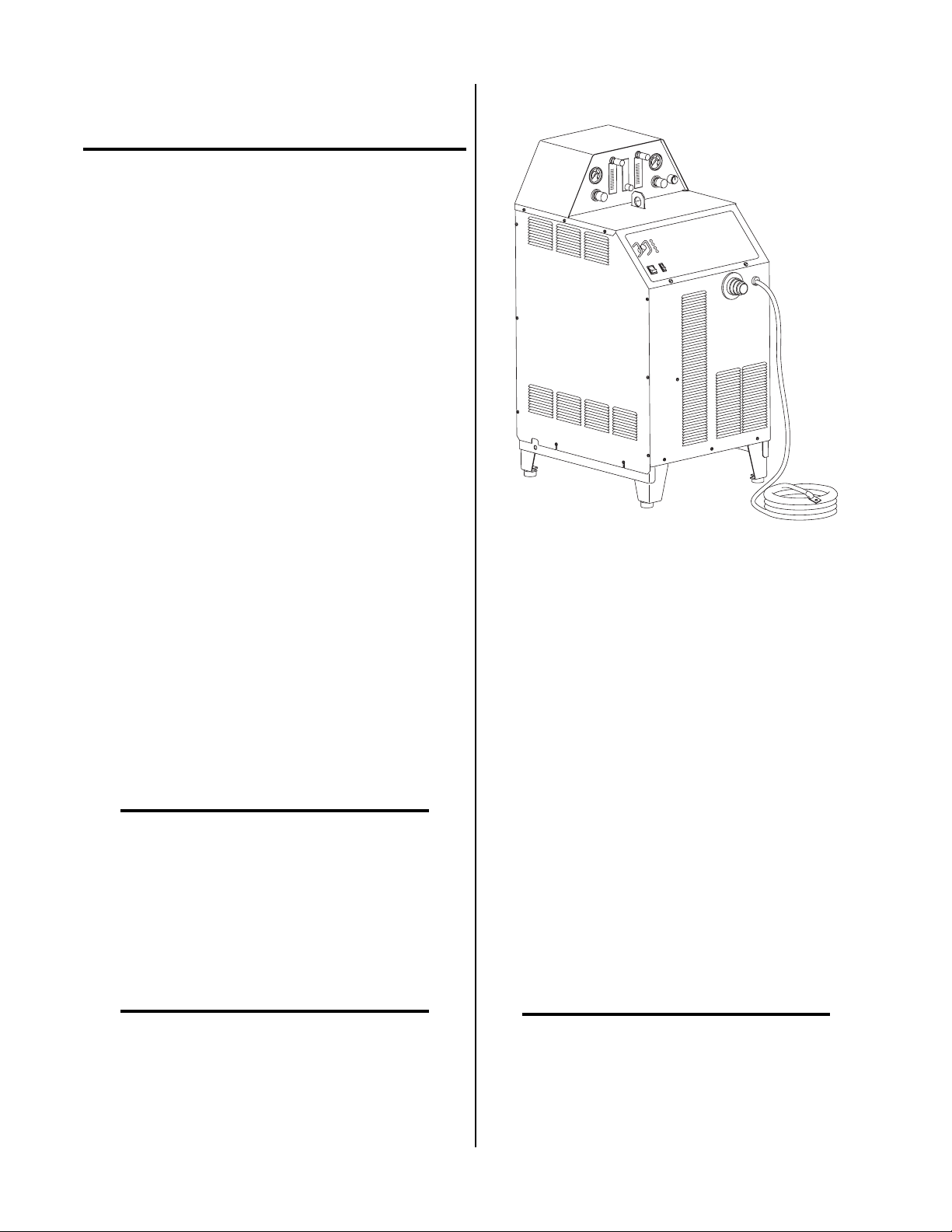
A-02157
Figure 2-1 Merlin 1000 Power Supply
The Standard Coolant supplied with the Power Supply
can be used in ambient temperatures down to 10° F
(-12° C). If the ambient temperature will be below 10° F
(-12° C) then Super Coolant should be used. This coolant
can be used in areas where the ambient temperature dr ops
to -34° F (-36° C).
A. Typical System
A typical system configuration will contain the following:
• Power Supply
• 20 ft (6.1 m) Work Cable and Ring Terminal
• Maximizer 300 180° T o rch with 25 ft (7.6 m) or 50 ft
(15.2 m) Lead length as ordered
• Maximizer 300 Spare Parts Kit
• CNC Interface Cable 25 ft (7.6 m) or 50 ft (15.2 m)
length as ordered or Remote Pendant Control
• Standard Thermal Ar c Coolant - 3 gallons
NOTE
The power supply can be ordered in various options factory installed.
Refer to Section 2.04 for list of Power Supply Options and Accessories.
Manual 0-2731 9 INTRODUCTION
Refer to Section 2.04 for complete list of Power Supply Options and Accessories.
Page 14

B. Requirements to Complete System
7. Duty Cycle
To complete the system, the user needs to provide the
following:
• Primary input power
• Gas supplies
2.03 Specifications & Design Features
The following specifications apply to the Power Supply
only:
1. Front Panel Controls
• ON/OFF and RUN/SET Switches
• Output Current Control
• Work Cable Connection
• Torch Leads Connection
2. Front Panel LED Indicators
• AC
• TEMP
• GAS Pressure/Coolant Flow
• DC Output
3. Gas Control Panel
• Plasma and Secondary Gas Pressure Controls and
Gauges
• Plasma Gas Flowmeter
• Secondary Lo-Flow Gas Flowmeter
• Secondary Mode Selector Switch
• Secondary Water Mist Flowmeter
4. Rear Panel
• Primary Input Power Cable Strain Relief
• Plasma Gas Supply Connection
• Secondary Gas Supply Connection
• Secondary Water Supply Connection
• Dual Stage Air Filter
5. Input Power (see NOTES)
380-415 VAC (±10%), 50/60 Hz, Three-Phase
NOTES
Refer to Appendix I for suggested input wiring size,
current ratings and circuit protection r equirements.
6. Output Power
100% Duty Cycle @ 130V output at 100 amps
8. Cut Capacity
Pierce and Production Rating: 1/2 inch (12.7 mm)
9 Pilot Circuitry
Capacitive Discharge (CD), Pulsed DC (See Note)
NOTE
Optional Remote Arc Starter available.
10. CNC Interface Signals
Start/Stop and OK-To-Move
11. Coolant Pressure
Internal Service-adjustable
130 psi (8.8 bar) at zero flow
120 - 125 psi (8.2 - 8.5 bar) at 0.6 gpm (2.3 lpm)
12. Coolant Flow Rate
0.5 gpm (1.9 lpm) with 150 feet of total torch and torch
leads at 70°F (21°C)
NOTE
The flow rate varies with lead length, torch configuration, ambient temperature, amperage level,
etc.
13. Cooling Capacity
4,000 to 10,000 BTU
NOTE
Maximum value based on “free flow” condition.
14. Coolant Reservoir Capacity
2 gallons (Use Thermal Arc® coolant only)
Capable of handling a total of 150 feet of torch lead
length
15. Secondary Water
Clean drinking quality tap water can be used as a secondary and must be capable of delivering the following minimums:
• Water pressure of 50 - 100 psi (3.5 - 6.9 bar)
• Flow of 9 gph (34 lph)
Continuously variable from 30 to 100 amps (±5%)
INTRODUCTION 10 Manual 0-2731
Page 15

16. Overall Dimensions
Height: 40-1/2 inches (1.03 m)
Width: 20-1/2 in (0.52 m)
Depth: 30-1/4 inches (0.77 m)
17. Weight
Power Supply with Torch: 275 lbs (125 kg)
2.04 Power Supply Options and Accessories
With a simple change of torch parts, the system can also
be used for plasma arc gouging. Plasma arc gouging uses
the same process to remove material to a controlled depth
and width.
B. Input and Output Power
The unit converts AC input power to DC power for the
main cutting arc. The negative output is connected to
the torch electrode through the negative torch lead, and
the positive output connects to the workpiece through
the work cable.
C. Pilot Arc
NOTE
Refer to Section 6, Parts Lists, for part numbers
and ordering information.
The following are accessories that are available for this
Power Supply:
A. High Pressure Regulators
High pressure regulators ar e available for air , oxygen,
argon-hydrogen and nitrogen. The r egulators are used
to set the proper pressure for the type of gas being
used.
B. Standoff Control (SC11)
Optional Standoff Control automatically finds height
and maintains torch standoff with a high speed torch
lifter motor . Refer to Standoff Control (SC1 1) Manual,
0-2556, for more information.
C. Remote Arc Starter
Option available to remote the arc starting circuits
closer to the Torch Head Assembly. The option includes a Remote Arc Starter and Torch Supply Leads.
The Torch Supply Leads are available in 25 ft (7.6 m)
to 100 ft (30.5 m) lengths.
When the torch is activated there is a 2 second (service
adjustable) gas pre-flow, followed by an uninterrupted
pulsed DC pilot arc established between the electrode and
tip. The pilot arc is initiated by a momentary high frequency pulse from the Power Supply or the Optional
Remote Arc Starter. The pilot creates a path for the main
arc to transfer to the work. When the main arc is established, the pilot arc shuts off. The pilot automatically restarts when the main arc stops, as long as the torch remains activated.
D. Main Cutting Arc
The power supply converts the AC input power to DC
power for the main cutting arc. The negative output is
connected to the torch electrode through the negative
torch lead. The positive output is connected to the workpiece via the work cable and ring lug connection.
E. RF Shielding
All machine torch systems are shielded to minimize radio frequency (RF) interference which results from the
high frequency arc initiation. These shielded systems are
designed with features such as a wire for establishing an
earth ground and shielded torch and control leads.
F. Interlocks
D. Remote Pendant Control
Control used to manually start and stop cutting operations from a location up to 25 ft (7.6 m) from the
Plasma Power Supply.
2.05 Theor y Of Operation
A. Plasma Arc Cutting and Gouging
Plasma is a gas which is heated to an extremely high temperature and ionized so that it becomes electrically conductive. The plasma arc cutting process uses this plasma
gas to transfer an electric arc to a workpiece. The metal
to be cut is melted by the intense heat of the arc and then
blown away by the flow of gas.
Manual 0-2731 11 INTRODUCTION
The system has several built-in interlocks to provide safe
and efficient operation. When an interlock shuts down
the system, the fault condition must be remedied and the
system recycled using the applicable control device.
1. Parts-In-Place (PIP) Interlock
The Power Supply has a built-in parts-in-place interlock that prevents accidental torch starting
when torch parts are not properly installed. A flow
switch on the coolant return lead detects reduced
coolant flow caused by improper torch assembly.
If not satisfied, the switch interrupts power to the
tip and electrode.
Page 16

2. Gas Pressure Interlock
A pressure switch acts as an interlock for the
plasma gas supply . If the plasma gas supply pressure falls below minimum requirements the pr essure switch will open, shutting off the power to
the contactors, and the GAS indicator will go out.
When adequate plasma supply pressure is available the pressure switch will close, allowing power
to be resumed for cutting.
NOTE
There is no gas pressure interlock for secondary
gas.
INTRODUCTION 12 Manual 0-2731
Page 17
SECTION 3:
INSTALLATION
vide sufficient clearance in front of the unit to allow access to the front panel controls (minimum 6 inches or 0.15
m).
PROCEDURES
3.01 Introduction
NOTE
Depending on how the system was ordered, some
Power Supply options may already be installed.
If option(s) have been factory installed some of the
instructions may not apply. It is recommended
that all sub-sections be read for general information.
This section describes installation of the Power Supply
and connecting the Torch.
These instructions apply to the Power Supply only; installation procedures for the Torch, Options, and Accessories are given in Manuals specifically provided for those
units.
The complete installation consists of:
1. Site selection
2. Unpacking
3. Connections to Power Supply
a. Input power
b. Work cable
c. Gas connections
d. Torch Installation
e. Connecting auxiliary devices
4. Grounding
5. Operator training
CAUTION
Operation without proper air flow will inhibit
proper cooling and reduce duty cycle.
Review the safety precautions in the front of this manual
to be sure that the location meets all safety requirements.
3.03 Unpacking
NOTE
Equipment that was ordered as a system is packaged in one shipping carton. All options and the
torch are factory installed.
Each component of the system is packaged and protected
with a carton and packing material to prevent damage
during shipping.
1. Unpack each item and remove all packing material.
2. Locate the packing list(s) and use the list to identify
and account for each item.
3. Inspect each item for possible shipping damage. If
damage is evident, contact your distributor and/or
shipping company before proceeding with system
installation.
3.04 Input Power Cable Connections
The Power Supply is factory wired to accept input voltages of 380-415 VAC, 50 or 60 Hz, three-phase power.
A. Power Source
The power source must conform to local and national electric codes. For suggested circuit protection and wiring
requirements refer to Appendix I.
3.02 Site Selection
Select a clean, dry location with good ventilation and adequate working space around all components.
NOTE
Review Important Safety Precautions (page 1) to
be sure that the selected location meets all safety
requirements.
The power supply is fan cooled by air flow through the
front panel to the rear panel. Air flow must not be obstructed. Provide at least 2 feet (0.61 m) in the rear and at
least 6 inches (0.15 m) on each side for clearance . Pro-
Manual 0-2731 13 INST ALLATION PROCEDURES
Disconnect primary power at the source before assembling or disassembling the Power Supply, torch
parts, or torch and leads assemblies.
B. Input Power Cable Connections
The shielded input power cable must be connected to a
380-415 V AC, three-phase power sour ce. Refer to the following procedure:
W ARNING
Page 18

CAUTION
The input power cable must not be modified in any
way as shielding is installed on the cable.
1. At the free end of the input power cable, cut back
the insulation on the individual wires approximately 1/8 - 3/16 inch (3-5 mm).
2. Connect the ends of the individual wires and shield
to a customer supplied plug or disconnect box per
the following (see NOTES):
• Brown wire to Line 1 (Live)
This sub-section includes information for connecting the
gas supplies to the Power Supply. The information is
grouped in paragraphs for different types of gases and
options per the following:
A. Using Shop Air
B. Using High-Pressure Gas Cylinders
C. Using Plasma Shop Air and Secondary High-
Pressure Gas Cylinder
D. Using Water Secondary
Refer to the appropriate paragraph(s) for the desired application to be used.
• Blue wire to Line 2 (Live)
• Black wire to Line 3 (Live)
• Y ellow/Gr een wire to Gr ound (power gr ound)
• Cable shield to earth ground
NOTES
The shield braid on the free end of the input cable
must be connected to a solid earth ground with as
short a connection as possible at the plug or disconnect box. Refer to Subsection 3.07 for procedures on installing an earth ground.
Make sure that the yellow/green wir e is connected
to power line safety ground.
3.05 Gas Connections
The Power Supply provides the liquid cooling and gases
to support operation of the Liquid Cooled Maximizer 300
T orch.
NOTE
Refer to the Liquid Cooled Maximizer 300 Torch
Instruction Manual (Cat. No. 0-2710) for information on plasma and secondary gas selection and
requirements.
The following are available gases that can be used with
the Liquid Cooled Maximizer 300 Torch:
A. Using Shop Air
NOTE
The Two Stage Air Line Filter Assembly is to be
used when using shop air as the Plasma Gas.
An inline pneumatic dryer/evaporator type air filter , capable of filtering particulates to at least 5 microns with a
dew point of 35°F (1.7°C), is required when using air fr om
a compressor. This type filter will insure that moisture,
oil, dirt, chips, rust particles, and other contminants from
the supply hose do not enter the torch. For highly automated applications, a refrigerated drier plus a particulate filter may be used to chill the air to remove all moisture.
CAUTION
Excessive oil or moisture in compressed air will
reduce torch parts life and cutting performance and
may cause torch failure.
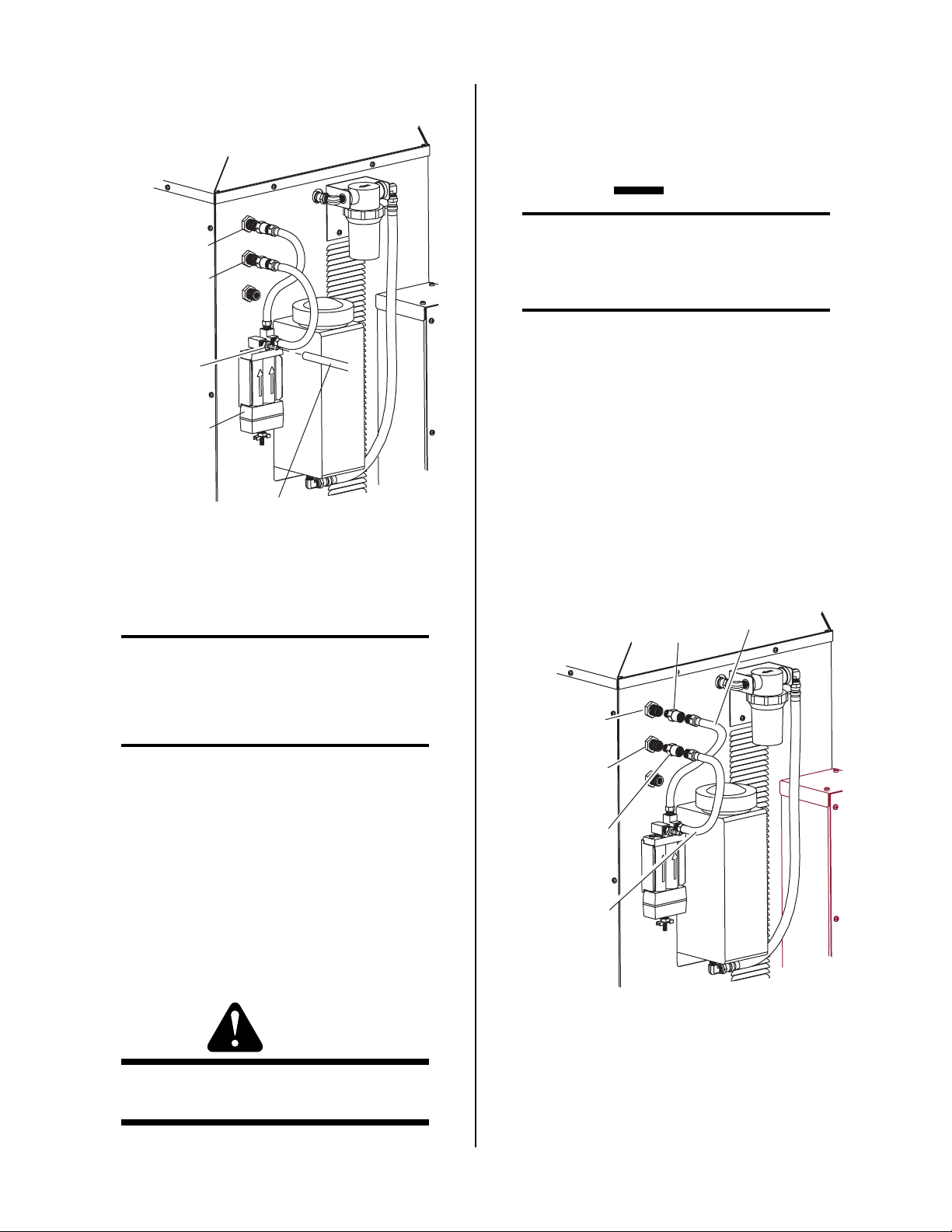
All Merlin 1000 Systems are supplied with a Two Stage
Air Line Filter attached to the rear of the Power Supply.
The following procedure is the recommended shop air
connection method:
Connect the air supply hose (see note) to the Air Line
Filter input port (IN) barb fitting and secure with a customer supplied hose clamp.
Plasma Gases: Compressed Air , Oxygen (O2), Nitr ogen (N2), or Argon/Hydrogen (Ar/H2)
Secondary Gases: Compressed Air, Oxygen (O2),
Nitrogen (N2), Carbon Dioxide (CO2), or Tap Water
Gas requirements vary depending on the application. The
gases are connected to the rear panel connections of the
power supply. Depending on the options installed and
the source of the gases will determine the installation of
filters and regulators.
INST ALLATION PROCEDURES 14 Manual 0-2731
Page 19
2. Each cylinder must be equipped with an adjustable
high-pressure regulator capable of pr essures up to 125
psi (8.6 BAR) maximum and flows of up to 700 scfh
(328 lpm) for cutting or gouging.
CAUTION
PLASMA GAS
SECONDARY
GAS
Barb Fitting
Two-Stage
Air Filter
Air Supply Hose
(Customer Supplied)
A-02348
Figure 3-1 Supply Hose Connections
NOTE
The supply hose must be 1/4 inch (6.3 mm) minimum inside diameter to provide adequate air flow .
Maximum input pressure to the internal regulator on the Power Supply must not exceed 125 psi
(8.6 BAR).
NOTE
A typical 50 lb. CO2 cylinder can deliver a continuous flow rate of 35 scfh (16.5 lpm). To obtain
the required flow rate for the torch, it may be necessary to manifold several CO2 cylinders. Continuous flow requirements will depend on the specific application and duty cycle.
3. Connect the gas supply to the Power Supply per
the following:
a. Remove the plasma and secondary gas hoses
and adapters from the PLASMA and SECONDARY fittings at the r ear panel.
Adapter
Fitting
Plasma Gas
Hose
B. Using High-Pressure Gas Cylinders
NOTES
Refer to the regulator manufacturer’s specifications
for installation and maintenance procedures. Refer to Section 6.05, System Options and Accessories, or a listing of available high-pressure regulators.
Do not use an air line filter with high pressure gas
cylinders.
1. Examine the cylinder valves to be sure they are clean
and free of oil, grease or any foreign material. Momentarily open each cylinder valve to blow out any
dust which may be present.
WARNING
Do not stand in front of the valve outlet when opening.
PLASMA GAS
Fitting
SECONDARY
GAS Fitting
Adapter Fitting
Secondary Gas
Hose
A-02355
Figure 3-2 Removal Of Factory Installed Hardware
b. Connect the gas hose from the plasma gas
source directly to the input fitting on the rear
panel of the Power Supply marked PLASMA.
Manual 0-2731 15 INST ALLATION PROCEDURES
Page 20

Plasma Gas
Hose
2. Each cylinder must be equipped with an adjustable
high-pressure regulator capable of pr essures up to 125
psi (8.6 BAR) maximum and flows of up to 700 scfh
(328 lpm) for cutting or gouging.
CAUTION
PLASMA GAS
Fitting
SECONDARY
GAS Fitting
Secondary Gas
Hose
A-02349
Figure 3-3 Gas Connections Using Gas Cylinders
c. Connect the gas supply hose from the second-
ary gas supply directly to the input fitting on
the rear panel of the Power Supply marked
SECONDARY.
Maximum input pressure to the internal regulator on the Power Supply must not exceed 125 psi
(8.6 BAR).
NOTE
A typical 50 lb. CO2 cylinder can deliver a continuous flow rate of 35 scfh (16.5 lpm). To obtain
the required flow rate for the torch, it may be necessary to manifold several CO2 cylinders. Continuous flow requirements will depend on the specific application and duty cycle.
3. Connect the gas supply to the Power Supply per
the following:
a. Remove the secondary gas hose and adapter
from the SECONDARY fitting at the rear panel.
Plasma Gas
Hose
C. Using Plasma Shop Air And Secondary
High-Pressure Gas Cylinder
NOTES
Refer to the regulator manufacturer’s specifications
for installation and maintenance procedures. Refer to Section 6.05, System Options and Accessories, for a listing of available high-pressure regulators.
Do not use an air line filter with high pressure gas
cylinders.
1. Examine the cylinder valves to be sure they are clean
and free of oil, grease or any foreign material. Momentarily open each cylinder valve to blow out any
dust which may be present.
W ARNING
Do not stand in front of the valve outlet when opening.
PLASMA GAS
Fitting
SECONDARY
GAS Fitting
Adapter Fitting
Secondary Gas
Hose
A-02356
Figure 3-4 Removal Of Factory Installed Hardwre
b. Connect the gas supply hose from the second-
ary gas supply directly to the input fitting on
the rear panel of the Power Supply marked
SECONDARY.
INST ALLATION PROCEDURES 16 Manual 0-2731
Page 21

2. Connect the tap water supply hose to the input of a
Water Pressure Regulator.
PLASMA GAS
Fitting
SECONDARY
GAS Fitting
Secondary Gas
Hose From Gas
Cylinder
Barb Fitting
Two-Stage
Air Filter
Unused Secondary
Air Hose
(End must be plugged)
A-02350
Plasma Gas
Hose
Plasma Air Supply Hose
(Customer Supplied)
3. Connect the output of the water regulator to the fitting
marked SECONDARY H2O (water) on the r ear panel
of the Power Supply.
WATER
Secondary
Figure 3-5 Gas Connections Using Shop Air and
High-Pressure Gas Cylinder
c. Connect the air supply hose (see note) to the
Air Line Filter input port (IN) barb fitting and
secure with a customer supplied hose clamp.
NOTE
The supply hose must be 1/4 inch (6.3 mm) minimum inside diameter to provide adequate air flow .
D. Using Water Secondary
NOTES
Tap water should only be used as a secondary on
machine torches.
The tap water source does not need to be deionized,
but in water systems with extremely high mineral
content a water softener is recommended.
Tap water with high levels of particulate matter
must be filtered.
Tap water can be used instead of a secondary gas and is
connected to the Power Supply as follows:
A-02351
Water Supply Hose
(Customer Supplied)
Figure 3-6 Secondary Water Connection
3.06 Connecting Torch Leads To
System Without Optional
Remote Arc Starter
NOTE
For Systems using the Optional Remote Arc Starter
refer to Section 3.13 for connecting the Torch.
WARNING
Disconnect primary power at the source before assembling or disassembling the power supply, torch
parts, or torch and leads assembly.
1. The tap water source must be capable of delivering a
minimum water pressure of 50 - 100 psi (3.5 - 6.9 bar)
and flow of 9 gph (34 lph).
The T orch Leads must be pr operly installed to the Power
Supply for proper operation. Make all torch connections
to the Torch Bulkhead Panel per the following:
Manual 0-2731 17 INST ALLATION PROCEDURES
Page 22

NOTE
Equipment ordered as a system will have the T or ch
factory connected to the Power Supply.
1. Turn the two latch screws securing the Control/Access Panel to the power supply front panel.
Latch Screw
Control/Access Panel
Latch Screw
A-02165
Figure 3-7 Front Control/Access Panel
2. Lift up on the Control/Access Panel to gain access to
the torch bulkhead panel.
Plasma (+)
Gas
Secondary
Gas
Coolant
Supply
A-02271
Torch Leads
Shield Stud
Control
Cable
Connector
Coolant
Return (-)
Control
Cable
Connector
Ring Lug
(Shielded T orches Only)
Figure 3-8 Torch Leads Connections
5. Feed the end of the torch leads through the rubber
boot in the front panel.
6. Connect torch coolant and gas leads to the connectors,
as indicated on bulkhead.
7. Remove one nut and star washer fron the torch lead
shield stud.
8. Place the ring lug from the torch lead shield wire over
the stud and secure with the nut and star washer.
9. Close the access panel and turn the two latching screws.
CAUTION
This system is designed for use with the Maximizer
300 Torch only . Do not connect any other torch to
this power supply.
3. Feed the end of the CNC/Remote Pendant Control
Cable, if used, through the rubber boot in the front
panel.
4. Connect the CNC/Remote Pendant Cable to Control
Cable Connector .
3.07 Work Cable And Ground Connections
A. Electromagnetic Interference (EMI)
Pilot arc initiation generates a certain amount of electromagnetic interference (EMI), commonly called RF noise.
This RF may interfere with other electronic equipment
such as CNC controllers, etc. To minimize RF interference, follow these grounding procedures when installing mechanized systems:
B. Creating an Earth Ground
NOTE
Refer to Appendix III for typical system grounding diagram.
1. Install a ground wire (not included) between the sys-
tem and a solid earth ground (also called star ground).
T o create a solid earth gr ound, drive a 1/2 in (12 mm)
diameter copper rod at least 6 - 8 ft (1.8 - 2.4 m) into
the earth so that the rod contacts moist soil over most
of its length. The required depth will vary depending on location (see NOTE). Locate the rod as close as
INST ALLATION PROCEDURES 18 Manual 0-2731
Page 23

possible to the power supply. The work table should
be connected to the same earth ground as the power
supply.
Coolant Reservoir
Filler Cap
NOTE
A properly installed ground rod will have a resistance of one ohm or less.
2. Connect the control device (CNC) to a separate earth
ground similar to the ground rod described above.
The ground cable should be at least 12 gauge wire.
3. To minimize RF interference, position torch leads as
far as possible (at least 1 ft or 0.3 m) from any CNC
components, drive motors, control cables, or primary
power lines.
4. Keep torch leads clean. Dirt and metal particles bleed
off energy, which causes difficult starting and increased chance of RF interference.
5. The work cable must have a solid connection to the
workpiece or cutting table (see NOTE). The connection must be free from dirt, gr ease, oil and paint.
NOTE
The work lead must be connected directly to the
workpiece or cutting table. DO NOT connect to
the ground rod and then to the workpiece or cutting table.
3.08 Filling Power Supply Coolant
The ambient temperature of the environment where the
Power Supply will be located determines the coolant to
be used. The Standard Torch Coolant supplied with the
system can be used in ambient temperatures down to
10° F (-12° C).
Optional Super Torch Coolant should be used in areas
where the ambient temperature drops down to -34° F
(-36° C).
CAUTION
Use only Thermal Arc Torch Coolant. Use of any
other coolant can result in torch damage, insufficient thermal protection, and/or pilot arc interference.
1. Locate the coolant deionizer bag and remove from
the plastic shipping bag.
2. Remove the coolant filler cap from the reservoir at
the rear of the Power Supply.
Deionizer
Bag
Coolant
Reservoir
Rear
Panel
Basket
A-02352
Figure 3-9 Coolant Reservoir
3. Carefully pour enough of the supplied Thermal
Arc Torch Coolant into the reservoir to fill it.
4. Reinstall the reservoir coolant filler cap.
5. After the complete system has been installed do
the following procedure to make sur e the coolant
has been pumped through the system (see NOTE):
NOTE
Depending on the length of the torch leads ordered
with the system more coolant may need to be added
after turning ON the system for the first time.
a. Place the ON/OFF Switch to ON.
b. After about 10 seconds the system will shut
down (see NOTE).
NOTE
DO NOT allow the pump to operate for more than
10 seconds the first time the system is turned ON.
c. Place the ON/OFF switch to OFF.
d. After 10 seconds place the ON/OFF switch to
ON again.
e. Repeat steps ‘b’ through ‘d’ until the system no
longer shuts down. Depending on the length
of the torch leads this sequence may need to be
done three to five times.
Manual 0-2731 19 INST ALLATION PROCEDURES
Page 24

f. After the system stays operational allow the
pump to operate for ten minutes to properly
purge any air from the coolant lines before using the system.
6. Remove the filler cap, re-fill the reservoir , place the
deionizer bag into the basket in the coolant reservoir and re-install the filler cap.
3.09 External Cable Connections
Depending on the options installed the Control Cable
must be connected to the Power Supply.
NOTE
Refer to the SC11 Standoff Control Instruction
Manual, 0-2556, for more information.
The standoff control remote cable connects to the
Power Supply Torch Bulkhead connector.
When the Standoff Control SC1 1 is used with this system the CNC Interface Cable is connected to the Standoff Control SC11. All Plasma Power Supply signals
are interfaced through the Standoff Control SC11.
C. Remote Hand Pendant
A. CNC Interface Cable
NOTE
Used when Standoff Control SC1 1 is not used.
The computer control interface (CNC) allows the
Power Supply to interface with a computer or other
control device.
Connect the supplied Power Supply/CNC Cable to
the Power Supply Torch Bulkhead connector.
NOTE
Refer to Appendix VI for CNC Interface Signal
Diagram.
Power Supply
Torch Bulkhead
Control Cable
Connector
The Remote Hand Pendant allows the operator to start
the cutting operation from a remote location.
Connect the Control Cable attached to the Remote
hand Pendant to the Power Supply Torch Bulkhead
connector.
3.10 Lifting Options
WARNINGS
Do not touch live electrical parts.
Disconnect input power conductors from de-ener-
gized supply line before moving unit.
The recommended method for lifting the power supply
is to use the built in lifting eye located in the Top Panel.
The unit may also be lifted using a forklift per the following procedure:
1. Approach from the front or rear of the unit.
2. Place the forks between the rear legs or the front
A-02167
legs.
3. Center the forks under the unit and carefully check
Standoff Control or CNC
Interface Cable
for proper balance before lifting.
W ARNING
Figure 3-10 Control Cable Interface Connection
B. Optional SC11 Standoff Control Cable
F ALLING EQUIPMENT can cause serious personal injury and equipment damage.
The Standoff Control automatically finds height and
maintains torch standoff with a high speed torch lifter
motor. The unit consists of a remote operator ’s con-
• Do NOT pull power supply by torch leads.
trol, torch lifter motor, and all cables required for installation. It is ordered and shipped separately.
INST ALLATION PROCEDURES 20 Manual 0-2731
Page 25

3.11 Optional Remote Arc Starter
A. Mounting Arc Starter Box
Mount the Arc Starter Box to the cutting table gantry per
the following procedure:
1. Remove the four screws securing the cover to the base
assembly of the Arc Starter Box.
A-02279
Screws
(Four Places)
Figure 3-11 Cover Screw Removal
2. Slide the cover up and off the base assembly.
Four Mounting Bolts And
Washers (Customer Supplied)
To Plasma
Power Supply
Figure 3-13 Mounting Bolt Installation
B. Connecting Torch
T o Torch
Base
Assembly
A-02281
WARNING
Cover
A-02280
Base Assembly
Figure 3-12 Cover Removal
3. Mount the base assembly of the Arc Starter Box to the
cutting table gantry using the four holes provided in
the base.
Disconnect primary power at the source before disassembling the torch or torch leads.
The Torch Leads connect directly to a bulkhead inside
the Remote Arc Starter. Connect the Torch Leads per the
following procedure:
1. Remove the cover from the Remote Arc Starter if
installed.
2. Feed the torch leads through the boot on the tor ch
end of the Remote Arc Starter.
3. Connect the torch leads connectors to the bulkhead
connections per the following figure.
NOTE
The last page of this Manual has a full size hole
template for use in locating the mounting holes.
Manual 0-2731 21 INST ALLATION PROCEDURES
Page 26

A-02282
Coolant
Return (-)
Left-Hand Thread
Coolant Supply
2. Feed the four hose assemblies on the T orch Supply
Leads through the boot on the lead end of the Ar c
Starter Box. The lead end of the Arc Starter Box
has a boot and control connector installed.
3. Connect the four hose assemblies to the internal
bulkhead per the following figure.
Torch Lead Shield
Secondary Gas
Plasma Gas (+)
Left-Hand Thread
Torch Leads
Figure 3-14 Torch Leads Connections
4. Connect the separate shield lead with ring terminal to the mounting stud on the bulkhead panel.
5. Check the torch for proper parts assembly.
CAUTION
The torch parts (gas distributor , electr ode, tip, and
shield cup) must correspond with plasma and secondary selection, output current level, and type of
operation (cutting or gouging). Refer to Section
4.04, Torch Parts Selection.
Coolant Return (-)
Coolant Supply
Left-Hand Thread
Control
Cable
Plasma Gas (+)
Left-Hand Thread
A-02283
Secondary
Gas
Figure 3-15 Torch Supply Leads Connections
4. Connect the other end of the Torch Supply Leads
fittings onto the mating connections at the bulkhead panel of the Plasma Power Supply.
Power Supply
Torch Bulkhead
Control Cable
Connector
6. Connect the Torch Supply Leads components to
the Remote Arc Starter (see NOTE).
A-02167
C. Connecting Torch Supply Leads
Standoff Control or CNC
Interface Cable
WARNING
Figure 3-16 Torch Supply Leads Connection To
Disconnect primary power at the source before dis-
Power Supply
assembling the torch or torch leads.
5. Connect the control cable connector to the mating
Connect one end of the Torch Supply Leads to the internal bulkhead inside the Arc Starter Box per the following:
1. Remove the cover from the Arc Starter Box if installed.
connector on the end of the Arc Starter Box.
6. The Power Supply requires internal changes when
the Optional Remote Arc Starter is to be used per
the following procedure:
a. Open the Front Control/Access Panel.
INST ALLATION PROCEDURES 22 Manual 0-2731
Page 27

b. Remove the panel by lifting the panel up and
off the studs being careful not to damage the
wiring.
c. Locate the Wiring Harness with Connector at-
tached, 14-pin CPC type, in the parts supplied
with the Remote Arc Starter.
d. At the rear of the Power Supply Bulkhead Panel
place the connector into the spare hole on the
left side as viewed from the front.
e. Secure the connector to the Power Supply Bulk-
head Panel with two screws.
Remote Arc Starter
Wiring Harness
Assembly
Ground Stud
J11 on CD Start
PC Board
Bulkhead
Panel
A-02287
Figure 3-17 Installation Of Wiring Harness
f. Locate the ground stud and remove one nut
and star washer.
g. Place the two wires with ring terminals over
the ground stud and secure with the nut and
star washer .
h. Locate the CD Start PC Board mounted to the
Center Chassis on the Power Supply.
i. Disconnect the plug connected to J11 on the right
side of the PC Board.
j. Reconnect the J11 plug to the mating connector
on the Wiring Harness with Connector installed
above.
k. Re-install the Front/Access Panel.
l. Connect the end of the Control Cable to the 14-
pin CPC connector mounted to the Power Sup-
ply Bulkhead.
Manual 0-2731 23 INST ALLATION PROCEDURES
Page 28

INST ALLATION PROCEDURES 24 Manual 0-2731
Page 29

SECTION 4:
OPERATION
A. Lower Front Panel
4.01 Introduction
This section provides a description of the Power Supply
operating controls and procedures. Identification of the
Front and Rear Panel components is followed by operating procedures.
4.02 Functional Overview
The Power Supply provides a degree of operating flexibility and the use of simple controls.
4.03 Front and Rear Panel Descriptions
This sub-section provides specific functional descriptions
of the Power Supply front and rear panel operating controls, indicators and connections. The Power Supply has
three main front panels and one rear panel. Each panel is
described in this sub-section as to the functions of the
connections, switches, and indicators.
Gas Control Panel
Rear
Panel
Lifting Eye
Control/Access
Panel
1
2
A-02170
Figure 4-2 Lower Front Panel
1. Work Cable Strain Relief
Strain relief to secure the factory installed work cable
with ring terminal to the Power Supply.
2. Torch Leads Boot
Connection inside at the bulkhead for the T orch Leads
Assembly. The connections supply all the required
signals, gases, and coolant for the torch.
B. Control/Access Front Panel
NOTE
Lower Front
A-02169
Figure 4-1 Main Front Panels
Panel
This panel is the access cover to the bulkhead area.
1. ON/OFF Switch
ON position activates all system control circuits when
remote or CNC enable is ON.
OFF position deactivates control circuits.
2. RUN/SET Switch
RUN position is used for torch operation.
SET position is used for setting gas pressures and
purging torch leads.
3. Current Control
Selects output current from 30-100 amps for the application on various materials and thicknesses.
Manual 0-2731 25 OPERATION
Page 30

7. DC Indicator
Green light indicates voltage is present at the power
supply output and cutting current is available.
3
1
A-02171
Figure 4-3 Left Side Of Control/Access Panel
4
5
6
7
C. Gas Control Front Panel
8
P
L
A
S
M
A
H2O
Plasma
Mist
Gas
A-02172
2
3
60
40
34
80
5
2
20
6
1
bar
psi
100
1
Lo-Flow
Gas
6
5
60
40
S
34
80
5
2
20
E
6
1
bar
C
psi
100
O
N
D
A
R
Y
4
Sec
Pressure
Lo-Flow
Gas
H
O
2
Mist
7
2
Figure 4-4 Gas Control Front Panel
1. Plasma Gas Pressure Control
Adjusts plasma gas pressure. Pull knob out and turn
clockwise to increase plasma pressure to desired level.
2. Plasma Gas Pressure Gauge
Displays plasma gas pressure from 0 - 160 psi (0 - 11
bar). Maximium gas pressure to be used is 100 psi
(6.9 bar).
4. AC Power Indicator
Green light indicates AC power is being supplied to
the system when the ON/OFF switch is in ON position. When switch is first set to ON, the indicator will
blink for approximately eight seconds indicating gas
purge at power on.
5. TEMP Indicator
Normally OFF. Yellow LED indicator will come ON
when the internal temperature sensors detect temperatures above normal limits. The unit should be allowed
to cool before continuing operation.
6. GAS/Coolant Flow OK Indicator
The LED is both a gas pressure and coolant flow indicator .
A green LED indicator ON means the input plasma
gas pressure is set to 30psi (2 bar or 207 kPa) or higher ,
and there is adequate coolant flow of greater than 0.2
gpm
The indicator will be OFF when the plasma gas pressure falls below 30 psi (2 bar or 207 kPa), there is not
enough coolant flow (less than 0.2 gpm, damaged
hose(s) or clogged filter(s), etc.
3. Plasma Gas Flowmeter
Controls flow rate of plasma gas supply.
4. Secondary Gas Pressure Control
Adjusts secondary gas pressure. Pull knob out and
turn clockwise to increase secondary pressure to desired level.
5. Secondary Gas Pressure Gauge
Displays secondary pressure from 0 - 160 psi (0 - 11
bar). Maximium gas pressure to be used is 100 psi
(6.9 bar).
6. Secondary Lo-Flow Gas Flowmeter
Controls flow rate of secondary Lo-Flow gas supply.
7. Secondary Mode Selector
Selects secondary mode of Sec Pressure, Lo-Flow Gas
or H2O Mist (water).
8. Secondary Water Mist (H2O) Flowmeter
Controls flow rate of secondary water supply.
D. Torch Bulkhead
The torch bulkhead is located under the Control/Gauge
Panel.
OPERA TION 26 Manual 0-2731
Page 31

E. Rear Panel
7
4
A-02173
3
2
6
Figure 4-5 Torch Panel Connections
1. Control Cable Connector
Connects the Standoff Control (SC11), CNC or
Remote Hand Pendant controls for the system.
2. Plasma (+) Gas Lead Connection
Left-hand thread fiting to connect the torch plasma
lead to the unit.
1. PLASMA Gas Input Fitting
1/4" NPT female gas fitting used to supply the plasma
gas to the system.
1
2. SECONDARY Gas Input Fitting
1/4" NPT female gas fitting used to supply the secondary gas to the system.
3. SECONDARY WATER Fitting
1/4" NPT female fitting used for connection of tap
5
water to the Power Supply. The water can be used as
a secondary gas for the torch when the front panel
SECONDARY switch is in the WATER position.
4. Coolant Reservoir and Filler Cap
The coolant reservoir supplies the system with coolant to cool the torch parts during operation. The maximum capacity of the reservoir is two gallons of coolant.
Inside the reservoir, in the filler neck, is a basket and
a deionizer bag. The bag removes charged particles
from the coolant after it is returned to the reservoir
and prevents the coolant from becoming conductive.
If the coolant in the reservoir breaks down because of
these charged particles then the coolant must be replaced.
3. Secondary Gas Lead Connection
Fitting to connect the torch secondary lead to the
unit.
4. Coolant Supply Lead Connection
Fitting to connects the torch coolant supply lead
to the unit.
5. Coolant Return (-) Lead Connection
Left-hand thread fitting to connect the torch coolant return lead to the unit.
6. Torch Lead Shield Stud
Stud used to secure the torch lead shield ring lug
when system is used without the Optional Remote
Arc Starter.
7. Optional Remote Arc Starter Control Connector
Connector used only when the Optional Remote
Arc Starter is installed. Connection for the control cable between the Power Supply and the Remote Arc Starter.
7
1
2
3
6
5
4
A-02353
Figure 4-6 Power Supply Rear Panel
Manual 0-2731 27 OPERATION
Page 32

5. Primary Input Power Filter, Cable and Strain Relief
5. Place RUN/SET switch to RUN mode.
The Input Filter Assembly is mounted to the rear panel
of the power supply. A strain relief is supplied to secure the shielded primary input AC power cable to
the Input Filter Assembly. The input cable is routed
through the strain relief and is connected to input terminals of an input filter .
6. Two Stage Air Line Filter
The Two Stage Air Line Filter will remove moisture
and contaminants from the air stream when using
compressed air. The filter is capable of filtering to at
least 5 microns.
7. Coolant Filter Assembly
The Coolant Filter Assembly mounted to the rear panel
is used to filter the coolant as it returns to the reservoir . The filter is a screen type which is easily cleaned
or replaced.
4.04 Sequence of Operation
The following is a typical sequence of operation for the
cutting system. Refer to Appendix II for a block diagram.
1. Close main power source disconnect.
a. AC power is available at the Power Supply.
a. Gas flow stops.
b. GAS indicator turns OFF.
6. Protect eyes and press or activate torch switch
a. Gas pre-flows starts.
b. GAS indicator turns ON.
7. After gas pre-flow (approximately 2 seconds)
a. Power supply enabled.
b. DC indicator turns ON.
c. Pilot relay closes.
8. Pilot arc is established
9. Move T orch within transfer distance of workpiece.
a. Main arc transfer.
b. Pilot arc OFF.
10. Complete cutting operation.
NOTE
If the torch is lifted from the workpiece, while still
having the torch activated, the main arc will stop
and the pilot arc will automatically restart.
2. Place RUN/SET switch to RUN mode.
3. Place the ON/OFF power switch on the front panel
of the Power Supply to ON.
a. Fan turns on.
b. Coolant Pump turns on.
c. AC Power indicator blinks ON and OFF for
eight seconds then stays ON. During this eight
seconds there is a start-up purge of gas through
the system (see NOTE).
NOTE
Gas will flow only if gas supply is connected, turned
on and gas regulator is not set to zero.
4. Place RUN/SET switch to SET mode.
a. Gas solenoid opens and gas flows to set pres-
sure.
b. GAS indicator turns ON.
NOTE
GAS indicator will not come ON if the gas pressure is set below 30 psi (2 bar or 207 kPa) at the
Plasma Gas Regulator or if coolant flow switch is
not satisfied.
11. Release or deactivate the torch switch.
a. Main arc stops.
b. Pilot arc stops (power supply enable signal re-
moved).
NOTE
If torch is activated during post-flow , pilot arc will
immediately restart.
If torch is within transfer distance of workpiece,
main arc will transfer.
12. Gas will flow for 20 seconds (post-flow).
a. Gas solenoid closes.
b. Gas flow stops.
c. GAS indicator turns OFF.
13. Place the ON/OFF power switch on the front panel
of the unit to OFF
a. AC Power indicator turns OFF.
b. Fans turn OFF.
14. Place the main power disconnect to open.
a. Main AC power is removed from the system.
OPERA TION 28 Manual 0-2731
Page 33

4.05 Preparations for Operating
Follow this set-up procedure each time the system is operated:
Select the desired secondary gas per the following:
1. If gas secondary is desired, set secondary mode
selector switch to gas cylinder symbol position.
NOTES
W ARNING
Disconnect primary power at the source before assembling or disassembling power supply, torch
parts, torch and leads assemblies or adding coolant.
A. Coolant Level Inspection
Check the coolant level in the coolant reservoir at the
rear of the unit. If the coolant is down from the top of
the reservoir more than 2 inches (50mm), add coolant.
B. Deionizer Bag Inspection
Check the condition of the deionizer bag in the reservoir basket. If the bag is a yellowish brown (straw
color) then replace the bag.
C. Torch Parts Selection
Check the torch for proper assembly. Install proper
torch parts for the application (refer to Maximizer 300
Torch Instruction Manual, Catalog No. 0-2710).
D. Input Power
Check the power source for proper input voltage.
Close main disconnect switch or plug unit in to supply primary power to the system.
E. Work Cable Connection
Check for a solid and clean work cable connection to
the workpiece. The area must be free from paint and
rust.
F. Torch Connection
Check that the torch is properly connected.
G. Plasma Gas Supply
Connect desired plasma gas. Make sure gas sources
meet requirements (refer to appr opriate T orch Instruction manual). Check connections and turn plasma gas
supply on.
H. Secondary Gas Supply
Connect desired secondary gas. Make sure gas sources
meet requirements (refer to T or ch Instruction Manual).
Check connections and turn secondary supplies on.
Tap water should only be used for secondary gas
on machine torches.
If tap water pressure is over 100 psi (6.9 bar) there
must be a Water Regulator (Catalog No. 8-6118)
installed between the water source and the Power
Supply.
2. If tap water secondary is desired, set secondary
mode selector switch to water tap symbol position and connect tap water to the Power Supply
rear panel at the secondary water connection. It
may take two or three minutes for the water to
start flowing out the front of the torch.
NOTE
Refer to the Torch Instruction Manual for proper
secondary gas selection.
I. Plasma Gas Purge
Move the Power Supply ON/OFF switch to the ON
position.
An automatic gas purge will remove any condensation that may have accumulated in the torch and leads
while the system was shut down. The gas purge duration is 20 seconds. After the purge is complete, if
the RUN/SET switch is in SET position, gases will
flow . If the switch is in RUN position ther e will be no
gas flow.
J. Current Output Level Selection
Select the desired current output level from 30-100
amps for the operation.
K. Pressure and Flow Settings
Move the RUN/SET switch to SET position. Set
plasma and secondary pressures. Set the desir ed gas
pressures and flows at the Gas Control Fr ont Panel as
follows:
1. Select the desired plasma and secondary gases by setting the Gas Control Module front panel switches to
the desired gas positions.
2. To set the Plasma Gas pressure and flow rate do the
following:
a. Fully open the valve on the top of the Plasma Gas
flowmeter .
c. Pull out the knob on the Plasma Gas regulator.
Manual 0-2731 29 OPERATION
Page 34

d. Turn the knob clockwise to increase or counter-
clockwise to decrease gas pressure.
e. Push the knob back in to lock the pressure setting.
f. Slowly close the valve on the top of the Plasma Gas
flowmeter until the desired flow rate is achieved.
3. To set the Secondary Gas pressure do the following:
a. Set the Secondary Mode Selector switch to Sec Pres-
sure position.
b. Pull out the knob on the Secondary Gas regulator.
c. T urn the knob clockwise to increase or counterclock-
wise to decrease gas pressure.
d. Push the knob back in to lock the pressure setting.
4. To set the Lo-Flow Gas flow rate do the following:
a. Set the Secondary Mode selector switch to Lo-Flow
Gas position.
4.06 Cut Quality
Cut quality requirements differ depending on application. For instance, nitride build-up and bevel angle may
be major factors when the surface will be welded after
cutting. Dross-free cutting is important when finish cut
quality is desired to avoid a secondary cleaning operation.
The following cut quality characteristics are illustrated
in Figure 4-7:
Cut Surface
The condition (smooth or rough) of the face of the cut.
Bevel Angle
The angle between the surface of the cut edge and a
plane perpendicular to the surface of the plate. A perfectly perpendicular cut would result in a 0° bevel
angle.
b. Fully open the valve on the top of the Lo-Flow Gas
flowmeter .
c. Pull out the knob on the Secondary Gas regulator.
d. Turn the knob clockwise to increase or counter-
clockwise to decrease gas pressure.
e. Push the knob back in to lock the pressure setting.
f. Slowly close the valve on the top of the Lo-Flow
flowmeter until the desired flow rate is achieved.
5. T o set the W ater (H2O) Mist flow rate do the following:
a. Set the Secondary Mode selector switch to H2O Mist
position.
b. Slowly open the valve on the top of the H2O Mist
flowmeter until the desired flow rate is achieved.
6. Place the RUN/SET switch to the RUN position.
NOTE
For recommended gas pressures and flows for various cutting operations refer to the Instruction
Manual, 0-2710, supplied with the Maximizer 300
T orch.
Top-Edge Rounding
Rounding on the top edge of a cut due to wearing
from the initial contact of the plasma arc on the workpiece.
Dross Build-up and Top Spatter
Dross is molten material which is not blown out of
the cut area and re-solidifies on the plate. Top spatter
is dross which accumulates on the top surface of the
workpiece. Excessive dross may require secondary
clean-up operations after cutting.
Kerf Width
The width of material removed during the cut.
Nitride Build-up
Nitride deposits which may remain on the cut edge
of the carbon steel when nitrogen is present in the
plasma gas stream. Nitride buildups may create difficulties if the steel is welded after the cutting process.
L. Ready for Operation
Return the RUN/SET switch to RUN position. The
system is now ready for operation.
NOTE
Refer to Appendix II for a detailed block diagram
of the Sequence of Operation.
OPERA TION 30 Manual 0-2731
Page 35

Top
y
y
y
y
Spatter
Build-Up
Kerf Width
Dross
Cut Surface
Drag Lines
Cut Surface
Bevel Angle
Top Edge
Rounding
A-00007
Description of Cut Characteristics
Excellent - Minimum bevel (0 - 4°), minimum kerf (2 x
tip orifice diameter), little or no dross, smooth
cut surface.
Good - Slight bevel (0 - 10°), slightly wider kerf (2-1/2 x
tip orifice diameter), some dross (easily removed), medium-smooth cut surface, slight top
edge rounding.
NR - Excessive bevel (over 10°), wide kerf (over 2-1/2 x
tip orifice diameter), medium to heavy dross, rough
cut surface, top edge rounding.
NOTES
Figure 4-7 Cut Quality Characteristics
Cut quality will vary on different types of and material
thicknesses. The following table shows the cut quality
that can be expected from this equipment for materials
with a thickness from gage to 1/2 inch (12.7 mm):
Table 4 -A Cut Quality on Various Materials
Type of Ga s e s Material Thick ne ss Carbon Steel Stainless Alumin um
Ga g e Excellent Goo d - Exce llent Goo d - Exce llent
Air Plasma and
Air Secondar
Nitrogen Plasma and
Air or C O 2 Secon dar
Gage to 1 inch Excellen t Good Good
1 to 1-1/2 inches Excellent Good Good
Ga g e NR Goo d - Exce llent Goo d - Exce llent
Gage to 1/2 inch NR Good - Excellent Good - Excellent
1/2 to 1 inch NR Good - Excellent Good - Excellent
Cut quality depends heavily on set-up and parameters such as torch standoff, alignment with the
workpiece, cutting speed, gas pressures, and operator ability.
Type of Material
Gage to 1/4 inch NR Good Good
Nitrogen Plasma and
Wa t er Secondar
Ar/H 2 Plasma a nd
N2 or CO2 Secondar
Oxygen Plasma and
Air Secondary
Oxygen Plasma and
Oxygen Secondary
1/4 to 1/2 inch NR Excellent Good - Excellent
1/2 to 1-1/2 inches NR NR NR
Gage to 1/4 inch NR NR NR
1/4 to 1/2 inch NR Good Excellent
1/2 to 1 inch NR Good Good
Gage to 1 inch Excellent NR NR
Gage to 1/4 inch Ex c ellen t NR N R
Manual 0-2731 31 OPERATION
Page 36

4.07 System Operation
B. Fold Back Feature
NOTE
Frequently review the safety precautions at the fr ont
of this manual.
This section contains operating information which is specific to the power supply. Detailed operating information for torches can be found in the appropriate Torch
Instruction Manual.
W ARNINGS
Disconnect primary power at the source before assembling or disassembling power supply, torch
parts, or torch and leads assemblies, or adding coolant.
It is not enough to simply move the ON/OFF
switch on the unit to OFF position when cutting
operations have been completed. Always open the
power supply disconnect switch five minutes after
the last cut is made.
A. Operational Suggestions
Should the torch tip contact the workpiece or molten
slag, the output current will immediately drop to 35
amps to minimize potential tip damage.
NOTE
The torch is not designed for drag cutting.
4.08 Optional Power Supply Settings
The following functions can be used to tailor a system for
special application requirements or unique user preferences. These functions are controlled by DIP switches
located on the Logic Control PC board in the power supply .
Remove the left side panel and locate the Logic Control
PC Board near to top center of the unit. Set the function
as required.
A. High/Low Speed Auto-Restart Function
(SW5)
The Plasma Power Supply is always in the Auto-Restart
mode. This means that at the end of the cut, if the ST ART
signal is still on, the pilot will restart automatically.
The suggestions below should be followed in all cutting
and gouging operations:
1. Wait five minutes before setting the ON/OFF switch
to OFF after operation. This allows the cooling fan to
run to dissipate operating heat from the power supply.
2. For maximum parts life, do not operate the pilot arc
any longer than necessary.
3. Use care in handling torch leads and protect them fr om
damage.
4. In continuous cutting applications using CO2, it is often necessary to manifold four to six cylinders together
to maintain adequate flow at operating pressures.
5. When using water as the secondary note the following:
• Use clean drinking quality tap water to help pre-
vent particulate build-up within the system water
secondary plumbing.
• Particulate contamination and bulid-up can cause
reduced consumable parts life and premature tor ch
failure.
An immediate pilot restart, when cutting over holes or
expanded metal at relatively slow speeds, may cause the
arc to transfer back to the piece just cut. This happens
because the torch has not had time to be moved away
from the cut piece and results in extra starts and unnecessary parts wear.
The High/Low Speed Auto-Restart switch, SW5, has two
settings as follows:
• Low Speed - adds a one-tenth second delay to the
pilot restart to prevent arc back conditions.
• High Speed - no delay required as it may delay
starting on the next edge.
• A cartridge type particulate water filter may assist
in achieving optimum cutting performance.
OPERA TION 32 Manual 0-2731
Page 37

Logic PC Board
Logic PC Board
A-02258
12
SW5
Figure 4-8 High/Low Speed Auto-Restart Switch
SW5 Location
Select the desired function as shown in the following
chart:
High/Low Speed Auto-Restart Function
Speed SW5-1 SW5-2
A-02288
12
SW3
Figure 4-9 Gas Pre-Flow Delay Switch SW3
Location
Select the proper gas pre-flow time for the total torch lead
length as shown in the following chart:
Gas Pre-Flow Delay Funct i on
High 0 (OFF) 0 (OFF)
Low * 1 (ON) 1 (ON)
* = F a ct ory Se t t in g
NOTE
The ON position is in the direction of the arrow on
the PC Board next to the switch.
B. Gas Pre-Flow Delay (SW3)
The pre-flow delay allows time for gases to flow to the
torch when the torch is activated. Pre-flow is immediately followed by pilot arc initiation. Gas Pre-Flow Delay is set depending on the total torch lead length used
in the system. All power supplies are factory set at 2 seconds and must be reset either to 3.4 or 4 seconds as required if total torch lead length in the system is over 60 ft
(18.3 m).
Pre-Flow
(Sec onds)
2 *
3.4
Total Torch
Lead Length
0 - 60 ft
(0 - 18. 3 m)
61 - 85 ft
(18.6 - 25.9 m)
4
86 - 125 ft
(26.2 - 38.1 m)
SW3-1 SW3-2
1 (ON) 1 (ON)
1 (ON) 0 (OFF)
0 (OFF) 0 (OFF)
* = Factory Setting
Manual 0-2731 33 OPERATION
Page 38

OPERA TION 34 Manual 0-2731
Page 39

SECTION 5:
MAINTENANCE &
CUSTOMER/OPERATOR
C. Six Months or Every 720 Arc Hours:
1. Remove and clean in-line filter screens.
2. Check cables and hoses for leaks or cracks, replace
if necessary.
SERVICE
5.01 Introduction
This section describes maintenance procedures, basic
troubleshooting and service performable by operating
personnel. No other adjustments or repairs are to be attempted by other than Thermal Dynamics Trained personnel.
For major troubleshooting and parts replacement procedures refer to Merlin 1000 Power Supply Service
Manual 0-2732.
5.02 Recommended Routine Maintenance Schedule
WARNING
Disconnect primary power to the system before disassembling the torch, leads, or power supply.
This schedule applies to all types of water cooled plasma
cutting systems. Some systems will not have all the parts
listed and those checks need not be performed.
NOTE
The actual frequency of maintenance may need to
be adjusted according tousage and the environment.
A. Daily Operational Checks or Every Six Arc
Hours:
1. Check torch parts, replace if damaged.
2. Check plasma and secondary supply and pressure/
flow .
3. Purge plasma gas line to remove any moisture
build-up.
4. Check deionizer bag/cartridge, replace if color is
predominantly yellow .
B. Weekly or Every 30 Arc Hours:
1. Blow or vacuum dust and dirt out of the entire
machine.
3. Check all contactor points for severe arcing or pits,
replace if necessary.
4. Check all pillow blocks and bearings, clean and
lubricate if necessary.
5. Check fans, pumps and hoses for wear or cracking,
replace if necessary.
D. Twelve Months or Every 1500 Arc Hours:
1. Drain coolant, fill with distilled water , turn on main
power switch and let machine run for approximately 30 minutes.
Drain distilled water and replace with Thermal
Arc Coolant. Use Standard Mix Coolant (Catalog
# 7-2850) or Super Mix Coolant (Catalog # 7-2959)
for environments below +10° F (-12° C).
2. Check radiator fins, clean and comb out if necessary.
3. Repeat six month maintenance.
5.03 General Maintenance
A. Power Supply Cleaning
To clean the unit, open the enclosure and use a vacuum
cleaner to remove any accumulated dirt and dust. The
unit should also be wiped clean. If necessary, solvents
that are recommended for cleaning electrical apparatus
may be used. Do NOT blow air into the power supply
during cleaning; make sure to always blow air out of the
unit. Blowing air into the unit can cause metal particles
to interfere with sensitive electrical components and cause
damge to the unit.
While the side panels are off, inspect the wiring in the
unit. Look for any frayed wires or loose connections that
should be corrected.
B. Coolant Filter Assembly
The filter screen should be cleaned periodically . Remove
the filter screen by unscrewing the filter holder from the
Coolant Filter Assembly on the rear panel. Clean the filter screen by rinsing with hot soapy water . Remove soap
residue by rinsing with clean hot water. Be sure that all
the soap has been removed and the screen is dry of water
before re-installing in the Coolant Filter Assembly.
Manual 0-2731 35 SERVICE
Page 40

Filter
Filter Holder
A-02152
Figure 5-1 Coolant Filter Assembly
2. Coolant Conductivity
The coolant conductivity level should be checked
if the pilot doesn't start.
Check the condition of the deionizer bag in the
reservoir basket, if the bag is yellowish brown
(straw color) replace the bag and coolant (see
NOTE).
NOTE
To accurately measure the coolant conductivity it
is recommended to use a Conductivity Sensor similar to Thermal Dynamics Model TDS-73 (Catalog
# 7-2844).
E. Draining and Replacing Coolant
Remove the old coolant from the Power Supply reservoir
per the following procedure:
C. In-Line Filter Assembly
The in-line filter screen should be cleaned periodically.
T o gain access to the In-Line Filter Assembly remove the
right side panel (viewed from the front of unit) of the
Power Supply. Remove the filter screen by unscrewing
the filter holder from the In-Line Filter Assembly. Clean
the filter screen by rinsing with hot soapy water . Remove
soap residue by rinsing with clean hot water. Be sure
that all the soap has been removed and the screen is dry
of water before re-installing in the In-Line Filter Assembly.
Filter
Filter Holder
1. Disconnect the coolant input hose to the Coolant
Filter Assembly at the rear panel.
2. Carefully lower the hose out the right side of the
Power Supply and drain the coolant into an acceptable container .
CAUTION
Handle and dispose of the used coolant per recommended procedures.
Coolant Hose
Connection
Coolant
Hose
A-02153
Figure 5-2 In-Line Filter Assembly
A-02354
Figure 5-3 Draining Coolant From Reservoir
D. Coolant Level and Conductivity
1. Coolant Level
The coolant level should be checked every day at
the rear panel coolant gauge. If the coolant in the
reservoir is more than 2 inches (50mm) from the
top of the reservoir then add Torch Coolant.
SERVICE 36 Manual 0-2731
3. Reconnect the hose to the Coolant Filter Assembly.
4. Remove Coolant Reservoir Filler Cap and install
new coolant and deionizer bag.
Page 41

5.03 Common Operating Faults
Listed below are common cutting problems followed by
probable causes of each. If the problems are caused by a
torch problem, refer to the appropriate T o rch Manual.
1. Insufficient Penetration
a. Cutting speed too fast
b. Torch tilted too much
c. Incorrect Gas Settings
d. Metal too thick
e. Worn torch parts
f. Cutting current too low
g. Non-Genuine Thermal Dynamics Parts
2. Main Arc Extinguishes
a. Cutting speed too slow
b. Torch standoff too high from workpiece
c. Cutting current too high
k. Restricted coolant flow
l. Non-Genuine Thermal Dynamics Parts
5. Poor Pilot Starting
a. Non-Genuine Thermal Dynamics Parts
b. High coolant conductivity
5.04 Common Operating Problems
WARNINGS
Disconnect primary power at the source before disassembling the power supply, torch, or tor ch leads.
Frequently review the Important Safety Precautions (page 1). Be sure the operator is equipped with
proper gloves, clothing, eye and ear protection.
Make sure no part of the operator’s body comes into
contact with the workpiece while the torch is activated.
d. Work cable disconnected
e. Worn torch parts
f. Non-Genuine Thermal Dynamics Parts
3. Excessive Dross Formation
a. Cutting speed too slow
b. Torch standoff too high from workpiece
c. Worn torch parts
d. Improper cutting current
e. Improper gas selection or settings
f. Non-Genuine Thermal Dynamics Parts
4. Short Torch Parts Life
a. Oil or moisture in gas source
b. Exceeding system capability (material too thick)
c. Excessive pilot arc time
d. Starting or finishing off the workpiece
e. Gas flow too low (incorrect pressure or flow setting)
f. Improperly assembled torch
g. Output current too high for parts being used
h. Torch tip contacting workpiece
i. Improper gas selection for parts being used
j. Damaged or loose torch head components
CAUTION
Sparks from the cutting process can cause damage
to coated, painted, and other surfaces such as glass,
plastic and metal.
NOTE
Handle torch leads with care and protect them fr om
damage.
A. Piloting
Piloting is harder on parts life than actual cutting because
the pilot arc is directed from the electrode to the tip rather
than to a workpiece. Whenever possible, avoid excessive
pilot arc time to improve parts life.
B. Torch Standoff
Improper standoff (the distance between the torch tip and
workpiece) can adversely affect tip life as well as shield
cup life. Standoff may also significantly affect the bevel
angle. Reducing standoff will generally result in a more
square cut.
C. Edge Starting
For edge starts, hold the torch perpendicular to the workpiece with the front of the tip at the edge of the workpiece at the point where the cut is to start. When starting
at the edge of the plate, do not pause at the edge and
force the arc to "reach" for the edge of the metal. Establish the cutting arc as quickly as possible.
Manual 0-2731 37 SERVICE
Page 42

D. Direction of Cut
In the torches, the plasma gas stream swirls as it leaves
the torch to maintain a smooth column of gas. This swirl
effect results in one side of a cut being more square than
the other . Viewed along the direction of travel, the right
side of the cut is more square than the left (Refer to Figure 5-4). To make a square-edged cut along an inside
diameter of a circle, the torch should move counterclockwise around the circle. To keep the square edge along an
outside diameter cut, the torch should travel in a clockwise direction.
Left Side
Cut Angle
Right Side
Cut Angle
W ARNING
There are extremely dangerous voltage and power
levels present inside this unit. Do not attempt to
diagnose or repair unless you have had training in
power electronics measurement and troubleshooting techniques.
Basic T roubleshooting
This manual covers a basic level of troubleshooting that
requires limited dissasembly and measurements. If major complex subassemblies are faulty, the unit must be
returned to an authorized service center for repair.
Follow all instructions as listed and complete each section in the order presented. For major troubleshooting
and parts replacement procedures refer to Merlin 1000
Power Supply Service Manual 0-2732.
A-00512
Figure 5-4 Side Characteristics Of Cut
E. Dross
Generally when dross is present on carbon steel, it is referred to as either "high speed or slow speed dross".
"High speed dross" usually forms a narrow bead along
the bottom of the cut edge and is very difficult to remove.
"Slow speed dross" will be in larger quantities but does
not adhere tightly to the cut edge and can be easily removed.
When cutting a troublesome steel, it is suggested that the
torch travel speed be reduced to produce "slow speed
dross". Any r equired cleanup can then be done by scrapping, not grinding.
Dross present on top of the plate (top spatter), is normally
caused by a slow torch travel speed or too high of a torch
standoff distance.
5.05 Troubleshooting Guide
How to Use This Guide
The following information is a guide to help the Customer/Operator determine the most likely causes for
various symptoms.
This guide is set up in the following manner:
X. Symptom (Bold Type)
Any Special Instructions (Text Type)
1. Cause (Italic Type)
a. Check/Remedy (Text Type)
Locate your symptom, check the causes (easiest listed first)
then remedies. Repair as needed being sure to verify that
unit is fully operational after any repairs.
A. AC Power LED OFF
1. Switch at customer's main power panel in OFF position.
a. Close main power panel switch
2. Input power not properly connected to customer's main
power panel
General
T roubleshooting and repairing this unit is a process which
should be undertaken only by those familiar with high
voltage high power electronic equipment.
SERVICE 38 Manual 0-2731
a. Check that input power is present and unit is
properly connected (refer to Section 3.04, Input
Power Connections)
3. Customer's main power line fuse(s) blown
a. Check main power panel fuse(s) and replace as
required.
Page 43

4. Unit internal fuse blown or loose
a. If blown, double check input voltage vs. volt-
age selection (indide of unit) and replace fuse
per Section 5.08-B. If fuse blows again, return
unit to an authorized service center.
5. Faulty components in unit
a. Return for repair or have qualified technician
repair per Service Manual.
B. AC Power LED ON; TEMP indicator ON
1. Airflow obstructed
a. Check for obstructed air flow and correct con-
dition.
2. Fan(s) blocked
a. Check and correct condition
3. Unit is overheated
a. Allow unit to cool down for about 5 minutes.
Make sure the unit has not been operated beyond duty cycle limit.
4. Input line voltage is low
a. Check and connect to proper input power line
D. AC Power LED ON; Fans operating; No cutting
output
1. Torch not properly connected to power supply
a. Check that torch leads are properly attached to
power supply
2. Faulty components in unit
a. Return for repair or have qualified technician
repair per Service Manual.
E. Limited or Low cutting output with no control
1. Incorrect setting of CURRENT control
a. Check and adjusted to proper setting.
2. Poor input or output connections
a. Check all input and output connections.
3. Low plasma gas flow
a. Check for leaks or restriction in gas supply line
b. Replace all Torch Consumables
4. Faulty components in unit
a. Return for repair or have qualified technician
repair per Service Manual.
5. Faulty components in unit
a. Return for repair or have qualified technician
repair per Service Manual.
C. Torch will not pilot when torch switch is activated
1. RUN/SET switch in SET position
a. Move switch to RUN position.
2. Start signal activated during 8 second power on time
a. Remove Start signal and wait until AC LED
stops flashing before sending Start signal
3. Gas pressure too high or too low
a. Set pressure per Cut Speed Charts in appropri-
ate Torch Manual.
4. Faulty torch parts
a. Inspect torch parts and replace if necessary (re-
fer to Torch Instruction Manual supplied with
torch).
5. Faulty components in unit
a. Return for repair or have qualified technician
repair per Service Manual.
F. Erratic or improper cutting output
1. Poor input or output connections
a. Check all input and output connections.
2. Faulty torch parts
a. Inspect torch parts and replace if necessary (re-
fer to Torch Instruction Manual supplied with
torch).
G. AC Power LED indicator ON; Cutting output
available; Fan(s) not operating
1. Fan blades blocked
a. Check and clear blades.
2. Faulty components in unit
a. Return for repair or have qualified technician
repair per Service Manual.
H. AC POWER LED indicator ON; Fans operate; No
gas flow
1. Gas not connected or pressure too low
a. Check source for at least 80 psi (5.5 bar).
b. Verify setting of Secondary Gas Mode switch.
Manual 0-2731 39 SERVICE
Page 44

2. Low flow in gas supply path
4. Blocked torch
a. Check for leak or restriction in gas supply lines,
replace as necessary
b. Check for damaged torch parts, replace as nec-
essary
3. Faulty components in unit
a. Return for repair or have qualified technician
repair per Service Manual.
I. Torch cuts but not adequately
1. Current set too low
a. Increase current setting.
2. Torch is being moved too fast across workpiece
a. Reduce cutting speed (refer to Instruction
Manual supplied with torch.
3. Excessive oil or moisture in torch
a. Hold torch 1/8 inch (3 mm) from clean surface
while purging and observe oil or moisture
buildup (do not activate torch)
4. Worn torch parts
a. Replace torch consumables.
5. Using wrong gas for material being cut
a. Use correct gas for operation.
J. GAS LED indicator OFF
1. Gas pressure set too low
a. Adjust pressur e
a. Check torch parts.
5. Faulty power supply
a. Isolate and replace component(s) per Service
Manual.
L. GAS Indicator flashing ON and OFF
1. Air in coolant lines
a. Run pump for ten minutes to purge air from the
coolant lines before using the system.
2. Coolant Level is low
a. Check for proper coolant level at rear panel
gauge
M. Leaking torch connection
1. Loose torch connection
a. Check connection making sure connector is fully
seated.
N. Weak or sputtering pilot; HF stays on during pilot
1. Plasma gas pressure too high
a. Adjust pressur e
2. Low OCV (normal 290-350 VDC) caused by improper
input voltage selection
a. Check input voltage connections
3. Faulty power supply
a. Isolate and replace component(s) per Service
Manual.
2. Faulty power supply
a. Isolate and replace component(s) per Service
Manual.
3. No coolant flow.
a. Return for repair or have qualified technician
repair per Service Manual.
K. GAS LED indicator OFF, plasma and/or secondary
gas does not flow
1. Low plasma pressure
a. Check plasma pressure
2. Secondary supply turned OFF (or cylinder empty)
a. Check secondary supply
3. Secondary Selector switch set to wrong position
a. Check and set switch to proper type of second-
ary being used
SERVICE 40 Manual 0-2731
O. Pilot arc ON; No main arc transfer (torch brought
within range of work)
1. Work cable not connected
a. Connect work cable securely
2. Faulty power supply
a. Isolate and replace component(s) per Service
Manual.
3. Faulty Optional Remote Arc Starter
a. Refer to 'T roubleshooting W ith Optional Remote
Arc Starter' below
P. AC indicator ON; GAS indicator light ON; torch is
activated; DC indicator light blinks
1. Shorted torch.
a. Isolate and replace component(s) per Torch
Manual.
Page 45

2. Faulty power supply.
a. Isolate and replace component(s) per Service
Manual.
Troubleshooting With Optional Remote Arc
Starter
NOTE
The following troubleshooting is to be used only if
the system has the Optional Remote Arc Starter
installed.
Q. Start signal given to the Power Supply. Gas flows
for selected pre-flow time. DC indicator is OFF,
does not even come ON momentarily.
1. Problem not in the Remote Arc Starter. The Power
Supply is has no DC voltage output.
a. Refer to the Power Supply Service Manual to
test the output of the Power Supply
S. Start signal given to Power Supply. Gas flows for
selected pre-flow time then DC indicator is ON
steady. Pilot doesn't come on and there is no
spark (no repetitive snapping sound) from the
spark gap in Remote Arc Starter.
1. Defective Remote Arc Starter PC Board.
a. Refer to Section 5.07 Test Procedures to isolate
the defective assembly.
5.07 Test Procedures For Optional Remote Arc Starter
WARNING
High voltage may be present in the Arc Starter
Box.
R. Start signal given to Power Supply. Gas flows for
selected pre-flow time then DC indicator is ON
steady. Pilot doesn't come on, but there is a spark
(repetitive snapping sound) from the spark gap in
Remote Arc Starter.
For the spark gap to fire, the Power Supply DC output has to be getting to the Remote Arc Starter.
1. Consumable Torch parts are shorted
a. Check or replace the consumable Torch parts
2. Arcing or burning inside Torch Head Assembly
a. Remove the consumables from the Torch Head
Assembly and check for signs of arcing or burning inside the torch head. Replace Torch Head
Assembly if required.
3. Arcing or burning between the To rch fittings or from
the fittings to the Mounting Tube
a. Remove the Torch Head Assembly from the
mounting tube and check for arcing or burning
between the fittings or from the fittings to the
tube. Repair as required.
4. Defective CD transformer
a. Check for arcing around the CD Transformer
(while spark gap is firing) and look for any
cracks in the ferrite cores. If either problem
exists replace the CD Transformer.
The following two things are needed for the spark gap to
fire in the Arc Starter Box:
• 36 VAC bias voltage
The 36 V AC should be present anytime the Power
Supply is turned ON. Refer to Appendix VI, 36
VAC Wiring Block Diagram.
• Greater than 220 VDC Power Supply output
The Power Supply DC output should be grearter
than 200 VDC when the Power Supply is activated
and the DC indicator is ON. The voltage will be
present across the torch tip (+) and electrode (-).
The following procedure is to isolate the faulty assembly
to the Remote Arc Starter PC Board, Power Supply, T orch,
Torch Leads, or Torch Supply Leads Assembly
1. Remove the START signal from the power Supply to
disable the DC high voltage from the Remote Arc
Starter.
2. Place RUN/SET in SET position.
3. Power Supply DC indicator is OFF.
4. Remove cover from Remote Arc Starter.
5. On the Arc Starter PC Board locate the red LED indicator . When the indicator is ON the 36 VAC between
J1-1 and J1-3 on the Logic PC Board is present to the
Arc Starter PC Board.
NOTE
Connector J1 must be connected to the Arc Starter
PC Board.
Manual 0-2731 41 SERVICE
Page 46

• If red LED is ON proceed to Step 15.
• If red LED is OFF proceed to Step 6
6. Remove connector J1 from the Arc Starter PC Board
and reconnect making a good connection.
7. On the Arc Starter PC Boar d check the red LED indicator .
• If red LED is ON proceed to Step 15.
• If red LED is OFF proceed to Step 8
8. Remove connector J1 from the Arc Starter PC Board.
9. Measure for 36 VAC between J1-1 and J1-3 on the connector .
• If 36 VAC is at the connector, Arc Starter PC Board
is defective.
• If 36 VAC is not present at J1 proceed to Step 10.
10. Place the RUN/SET switch on the Power Supply to
the RUN position.
11. Place the main power switch on front panel of the
Power Supply to OFF.
12. Remove the Remote Arc Starter Control Cable from
the bulkhead connection, J14, at the front panel of the
Power Supply.
13. T urn the main power switch on the front of the Power
Supply to ON.
14. Check for 36 VAC between pins 5 and 8 of the Torch
Control connector (J14) at the Power Supply bulkhead.
NOTE
Refer to the Power Supply Operating and Service
manuals for more details.
WARNING
High voltage (300-400vdc) is present in Remote
Arc Starter.
17. Measure between E1(+) and E2 (-) on the Ar c Starter
PC Board.
WARNING
DO NOT accidently measure P1 and P2, studs
and brass nuts, where the CD Transformer (T1)
connects to the Arc Starter PC Board.
• If voltage more than 220 VDC is present Arc Starter
PC Board is defective.
NOTE
A dirty or incorrect gap in spark gap could cause
the same problem. Gap should be 0.015 +/- 0.001"
and is not adjustable.
• If voltage is less than 220 VDC, proceed to Step 18.
18. In the Power Supply measure the DC voltage between
the negative power lead and the red pilot lead.
• If greater than 220 VDC, check for open connec-
tions through the Power Supply connections, T orch
Supply Leads Assembly, and Remote Arc Starter
input and output connections.
• If less than 220 VDC, can be caused by a shorted
torch or torch leads.
• If not present, problem is in the Power Supply.
• If present, check for open in Torch Supply Leads
Assembly signal wires.
15. If the Arc Starter PC Boar d 36 VAC red LED was ON
from the test in Step 5 or 9, place RUN/SET to RUN
position.
16. Press start and go through a start sequence. After
pre-flow the DC indicator is ON. When the Power
Supply is activated and the DC indicator is ON, there
should be greater than 220 VDC between the torch
tip (+) and electrode (-).
SERVICE 42 Manual 0-2731
• No voltage can be caused by the Pilot Control (PCR)
contactor in the Power Supply not closing. Refer
to the Power Supply Service Manual under symptoms of No Pilot.
Page 47

5.08 Power Supply Parts Replacement
5. To reinstall the left side panel do the following:
a. Place the left side panel onto the frame and slide
the top edge under the lip on the top panel.
WARNING
Disconnect primary power at the source before assembling or disassembling the Power Supply, torch
parts, or torch and leads assemblies.
A. Left Side Panel Removal
The Left Side Panel of the Power Supply is the panel on
the left side of the unit as viewed from the front of the
unit.
NOTE
There is a ground wire connected to the inside of
the side panel. Use caution when removing.
1. Remove the eight screws securing the left side panel
to the frame assembly.
2. Loosen the two bottom screws in the slotted holes.
b. Reinstall all the screws to secure the left side panel.
B. Fuse Replacement
1. Remove the left side panel per paragraph "A"
above.
2. Locate the internal fuse near the top of the center
chassis on the left side of the unit.
3. Replace the fuse (5 amp, 600V).
4. Reinstall the left side panel per paragraph "A"
above.
Center Chassis
A-02347
Figure 5-5 Removing Left Side Panel
3. Pull the top of the Panel out and then lift up to remove
the panel from the Power Supply a short distance (see
note).
NOTE
There is a ground wire attached to the inside of the
side panel.
4. Remove the nut securing the ground wire to the side
panel.
Fuse
A-02357
Figure 5-6 Internal Fuse Location
C. Coolant Filter Assembly Replacement
The Coolant Filter Assembly is located on the rear panel
of power supply.
1. Remove the two Coolant Hose connections to the
Coolant Filter Assembly.
Manual 0-2731 43 SERVICE
Page 48

Coolant Filter Assembly
A-02156
Coolant
Hose
Flow
Switch
Assembly
In-line
Filter
Assembly
Elbow
Fitting
Bracket
A-02155
Coolant Hoses
Figure 5-7 Coolant Filter Replacement
2. Remove the two elbow fittings on each side of the
Coolant Filter Assembly and remove the damaged
assembly from the bracket.
3. Clean the old thread sealer from the thr eads of the
elbow fittings.
4. Apply a thin coating of liquid teflon thread sealer
to the threads of the elbow fittings.
5. Place the replacement Coolant Filter Assembly in
the bracket with the arrow pointing to the left and
reinstall the two elbow fittings.
6. Reconnect the two Coolant Hoses to the Coolant
Filter Assembly making sure that the hose to the
Pump Assembly is on the output of the Coolant
Filter Assembly (left side as viewed from the side
of unit).
Figure 5-8 In-Line Filter Replacement
4. Disconnect the Flow Switch Assembly at the top of
the In-Line filter Assembly.
5. Clean the old thread sealer from the thr eads of the
hoses and the fittings.
6. Apply a thin coating of liquid teflon thread sealer
to the threads of the fittings.
7. Reconnect the Coolant Hose coming from the Radiator Assembly to the bottom of the In-Line Filter Assembly .
8. Reconnect the top of the In-Line Filter Assembly to
the Flow Switch Assembly.
D. In-Line Filter Assembly Replacement
The In-Line Filter Assembly is located inside behind the
right side panel (viewed from the front of the unit).
1. Remove the right side panel from the Power Supply per paragraph 'A' above.
2. Locate the In-Line Coolant Filter near the center of
the unit.
3. Remove the Coolant Hose connection at the bottom of the In-Line Filter Assembly.
SERVICE 44 Manual 0-2731
Page 49

SECTION 6:
PARTS LISTS
6.01 Introduction
A. Parts List Breakdown
The parts list provide a breakdown of all r eplaceable components. The parts lists are arranged as follows:
Section 6.03 Complete System Replacement
Section 6.04 Power Supply Replacement Only
Section 6.05 Basic Replacement Parts
Section 6.06 Options and Accessories
NOTE
Parts listed without item numbers are not shown,
but may be ordered by the catalog number shown.
B. Returns
If a Thermal Dynamics product must be returned for service, contact your Thermal Dynamics distributor. Materials returned to Thermal Dynamics without proper authorization will not be accepted.
6.02 Ordering Information
Order replacement parts by catalog number and complete
description of the part or assembly, as listed in the parts
list for each type item. Also include the model and serial
number of the torch. Addr ess all inquiries to your authorized Thermal Dynamics distributor .
Manual 0-2731 45 P A RTS LISTS
Page 50

6.03 Complete System Replacements
Includes the following components: Power Supply with shielded input power cable, work cable and clamp, torch
and leads (as ordered), coolant, torch spare parts kit, CNC interface cable and operating manual.
Qty Description Catalog #
1 Merlin 1000 with 180° torch with 25 ft (7.6 m) Leads 1-9020
1 Merlin 1000 with 180° torch with 50 ft (15.2 m) Leads 1-9021
6.04 Power Supply Replacement Only
Includes: Power Supply with shielded input power cable, work cable and clamp
Qty Description Catalog #
1 Merlin 1000 Power Supply 3-9020
6.05 Basic Replacement Parts
Qty Description Catalog #
1 In-Line Filter 8-3460
1 Coolant Filter 8-4276
1 gal Torch Coolant
Standard 25/75 Mix for Ambient Temperatures to +10°F (-12°C) 7-2850
Super 50/50 Mix for Ambient Temperatures to -34°F (-36°C) 7-2959
1 Deionizer Bag 8-3312
1 Shielded Input Power Cable 9-7890
6.06 Options and Accessories
Qty Description Catalog #
1 Two Stage Air Filter Kit 9-1020
Replacement Elements
1 First Stage 9-1021
1 Second Stage 9-1022
1 Remote Pendant Control 7-3114
1 Remote Arc Starter Kit 3-6825
Includes internal Power Supply conversion and Remote Arc Starter assembly
1 Arc Starter Supply Leads (Used with Remote Arc Starter only)
Refer to Appendix V for parts list
PARTS LISTS 46 Manual 0-2731
Page 51

APPENDIX I: INPUT WIRING REQUIREMENTS
Inp ut Power Inp u t Current Sug gested Sizes (Se e No te s)
Voltage F req. 3-Ph 3-Ph Fuse (Amps )
(Volts) (Hz) (kVA) (Amps) 3-Ph 3-Ph
380 50/60 24.4 37 50 10
415 50/60 24.4 34 50 10
Line Voltages with Suggested Circuit Protection and Wire Sizes
Wire (mm
2
)
NOTES
Refer to Local and National Codes or local authority having jurisdiction for proper wiring requirements.
Cable size is de-rated based on the Duty Cycle of the equipment.
The suggested sizes are based on flexible power cable with power plug installations. For hard-wired installations refer
to local or national codes.
Cable conductor temperature used is 167° F (75° C).
An energy limiting fuse UL Class RK-1 (examples: BUSS LPS/LPN-RK or Gould-Shawmut AZK-A6K) should be
used to minimize damage to Plasma Cutting, Welding or power distribution equipment.
NEVER use replaceable element fuses like UL Class H, or "one-time" fuses like UL Class K5.
Manual 0-2731 47 APPENDIX
Page 52

APPENDIX II: SEQUENCE OF OPERATION
(BLOCK DIAGRAM)
ACTION
Close external
disconnect switch
RESULT
• Power to system
ACTION
Protect eyes and
activate torch
RESULT
• Gas indicator ON
• Gas pre-flow
• Main contactor
closes
• DC indicator ON
• Pilot contactor
closes
• Pilot arc established
ACTION
Enable ON
ON/OFF switch to ON
RESULT
• AC indicator ON
• TEMP Indicator ON
• GAS indicator ON
• Fan and pump ON
• 20 second auto-purge
PILOT ARC
ACTION
RUN/SET switch
to SET
RESULT
• Gas solenoids open,
gases flow to set
pressures
• GAS indicator ON
ACTION
RUN/SET
switch to RUN
RESULT
• Gas flow stops
• Power circuit ready
• GAS indicator OFF
ACTION
Torch removed from
work
RESULT
• Main arc stops
• Pilot arc auto-restart
ACTION
Torch moved to
within
1/8 - 3/8 inch of
work
ACTION
Torch de-activated by torch switch
released or remote device
RESULT
• Main arc stops
• Main contactor opens
• DC indicator OFF
NOTE- If torch is activated during post-flow
the pilot arc will immediately restart. If
within range of work, main arc will transfer.
After post-flow:
• Gas solenoids close, gas flow stops
• GAS indicator OFF
ACTION
ON/OFF switch to
OFF
RESULT
• AC indicator OFF
• TEMP Indicator OFF
• Fan and pump OFF
RESULT
• Main arc transfer
• Pilot arc OFF
ACTION
Open external
disconnect
RESULT
• No power to system
A-02175
APPENDIX 48 Manual 0-2731
Page 53

APPENDIX III: TYPICAL MECHANIZED SYSTEM
GROUNDING DIAGRAM
Connection for Systems
Without Standoff Control
CNC Control
Shielded Input
Power Cable
3-Phase
Input
& Ground
{
Plasma Power
Supply
Earth Ground
For Shielded Input
Power Cable
Standoff Control
Work Cable
NOTES
CNC Control
Earth
Ground
Workpiece
Earth
Ground
A-02359
Work Cable must connect directly
to workpiece. DO NOT connect Work Cable
to earth ground and then to workpiece.
Shielded input power cable must be
grounded to earth ground at plug or
disconnect end.
Manual 0-2731 49 APPENDIX
Page 54

APPENDIX IV: TYPICAL MECHANIZED SYSTEM CABLE
INTERCONNECTION DIAGRAM
NOTE
Refer to Appendix V for complete
data on the Cables and Hoses.
120/220 VA C
CNC CONTROL
With Standoff Control
CNC CONTROL
Without Standoff Control
3-Phase
Input
J
External +48 vdc
Power Supply
Merlin 1000
Power Supply
I
J100
J22
J41
SC-11 Standoff
I
J40
J42
A
Control
E
J43
Remote Arc Starter
J101
D
F
Torch
Torch Lifter
Assembly
OR
G
H
B
Workpiece
C
Earth
Ground
A-02634
APPENDIX 50 Manual 0-2731
Page 55

APPENDIX V: QUICK REFERENCE TO INTERCONNECTING
CABLES AND HOSES
Identifier Description Catalog #
A Remote St andoff Control Cable
50 ft (15.2 m) 9-9021
75 ft (22.9 m) 9-9022
100 ft (30.5 m) 9-9023
B* Remote A rc S tarter Control Cable
35 ft (10.7 m) 9-9016
50 ft (15.2 m) 9-9017
75 ft (22.9 m) 9-9018
100 ft (30.5 m) 9-9019
C W ork Cable, 22 ft (6.7 m ) 9-7792
D Lifter Motor Cable
10 ft (3.0 m) 9-4535
15 ft (4.6 m) 9-4536
20 ft (6.1 m) 9-4537
25 ft (7.6 m) 9-4538
40 ft (12.2 m) 9-7795
50 ft (15.2 m) 9-4539
E* Coolant S upply/Negati ve Hos e
35 ft (10.7 m) 9-9000
50 ft (15.2 m) 9-9001
75 ft (22.9 m) 9-9002
100 ft (30.5 m) 9-9003
F* Coolant Ret urn Hos e
35 ft (10.7 m) 9-9012
50 ft (15.2 m) 9-9013
75 ft (22.9 m) 9-9014
100 ft (30.5 m) 9-9015
G* Plasm a Gas/P ositi ve Hos e
35 ft (10.7 m) 9-9004
50 ft (15.2 m) 9-9005
75 ft (22.9 m) 9-9006
100 ft (30.5 m) 9-9007
H* Secondary Gas Hose
35 ft (10.7 m) 9-9008
50 ft (15.2 m) 9-9009
75 ft (22.9 m) 9-9010
100 ft (30.5 m) 9-9011
I CNC Cont r ol Cable
25 ft (7.6 m) 9-5651
50 ft (15.2 m) 9-5652
J 48 vdc Power Supply Power Cord 9-9025
* - Required when using Remote Arc Starter
Manual 0-2731 51 APPENDIX
Page 56

APPENDIX VI: POWER SUPPLY CNC INTERFACE
DIAGRAM
NOTE
Cable connections from Cutting Machine Controller (CNC) to Plasma Power Supply without any Standoff Control
Accessory.
Cutting Machine CNC Cable
START/STOP
Start Motion
(OK-To-Move)
Shield
Red
Black
Blue
Orange
White
Green
J22
3
4
10
11
12
14
Power Supply
Source 15 vdc, 10ma
Not Used
Not Used
2A, 125 VAC
28 vdc
A-02259
APPENDIX 52 Manual 0-2731
Page 57

APPENDIX VII: OPTIONAL REMOTE ARC STARTER
INTERCONNECTING DIAGRAM
A-02131
Manual 0-2731 53 APPENDIX
Page 58

APPENDIX VIII: 36 VAC CIRCUIT DIAGRAM
Auxiliary
Transformer
Outputs
36 V AC
115 V AC
J1
3
5
1
2
6
Logic PC
Board
J3
CD PC Board
J11
J5
Input Voltage
Sense
312
ON/OFF
Switch
132
17 18 19
132
4
Pilot/Output
PC Board
14
J4
5
7
3
2
1
4
J4-7
15
16
J4-5
J13
J9
1
5
7
3
2
4
J9
Gate Drive
PC Board
A-02325
1
2
3
4
5
7
Gate Drive
PC Board
APPENDIX 54 Manual 0-2731
Page 59

Manual 0-2731 55 APPENDIX
Page 60

APPENDIX IX: SYSTEM SCHEMATIC
A-02346
APPENDIX 56 Manual 0-2731
Page 61

A-02346
Manual 0-2731 57 APPENDIX
Page 62

APPENDIX 58 Manual 0-2731
 Loading...