

Page 1

Plasma Cutting
System
PAK 10
Instruction Manual
April 12, 2002 Manual No. 0-0515
Page 2

WARNINGS
Read and understand this entire Manual and your employer’s safety practices before installing, operating, or servicing the equipment.
While the information contained in this Manual represents the Manufacturer's best judgement, the
Manufacturer assumes no liability for its use.
Plasma Cutting System PAK 10
Instruction Manual Number 0-0515
Published by:
Thermal Dynamics Corporation
82 Benning Street
West Lebanon, New Hampshire, USA 03784
(603) 298-5711
www.thermal-dynamics.com
Copyright 1984 by
Thermal Dynamics Corporation
All rights reserved.
Reproduction of this work, in whole or in part, without written permission of the publisher is prohibited.
The publisher does not assume and hereby disclaims any liability to
any party for any loss or damage caused by any error or omission in
this Manual, whether such error results from negligence, accident, or
any other cause.
Printed in the United States of America
Publication Date: April 12, 2002
Record the following information for Warranty purposes:
Where Purchased:_________________________________________
Purchase Date:____________________________________________
Power Supply Serial #:_____________________________________
Torch Serial #:_____________________________________________
Page 3

Contents
SECTION 1:
GENERAL INFORMATION ....................................................................................................i
1.01 Notes, Cautions and Warnings ..........................................................................i
1.02 Important Safety Precautions............................................................................i
1.03 Publications...................................................................................................... ii
1.04 Note, Attention et Avertissement ..................................................................... iii
1.05 Precautions De Securite Importantes.............................................................. iii
1.06 Documents De Reference ............................................................................... v
1.07 Declaration of Conformity ............................................................................... vii
1.08 Statement of Warranty................................................................................... viii
SPECIFICATIONS ........................................................................................................................ 1
1.1. DESCRIPTION OF EQUIPMENT ................................................................... 2
1.2. SPECIFICATIONS........................................................................................... 2
1.3. PLASMA CUTTING........................................................................................ 3
1.4. THEORY OF OPERATION.............................................................................. 3
INSTALLATION............................................................................................................................. 5
2.1 UNPACKING ................................................................................................... 5
2.2 EQUIPMENT ASSEMBLY ............................................................................... 5
2.3 EQUIPMENT INST ALLATION ......................................................................... 6
OPERATION ................................................................................................................................. 9
3.1 OPERATING CONTROLS............................................................................... 9
3.2 PRE-OPERATION SET-UP ............................................................................. 9
3.3 OPERATION ................................................................................................. 10
3.4 CUTTING CURRENT AND SPEED SELECTION......................................... 13
SERVICE.................................................................................................................................... 15
4.1 TORCH MAINTENANCE .............................................................................. 15
4.2 TORCH LEADS AND LEADS EXTENSION PACKAGES .............................. 17
4.3 PAK UNIT MAINTENANCE ........................................................................... 18
4.4 GAS PRESSURE REGULATORS................................................................. 18
4.5 TROUBLE SHOO TING GUIDE..................................................................... 19
4.6 TEST PROCEDURES................................................................................... 21
PARTS LISTS ............................................................................................................................. 25
General Arrangement............................................................................................ 25
PAK 10 Cutting System ......................................................................................... 26
Equipment Board Assembly .................................................................................. 28
Control P.C. Board Assembly................................................................................. 29
Control Bridge and Main Bridge Assemblies ......................................................... 30
Torch Connection Panel Assembly ........................................................................ 32
Pilot Resistor and Rear Panel Assembly ............................................................... 34
Front P anel Assembly ........................................................................................... 36
Base Components Assembly ................................................................................ 38
Torch Leads, Leads Extension Packages, Torch Guide and
Circle Cutting Attachment, Remote Control Assembly .................................. 40
Series 4B Gas-Cooled Torches ............................................................................. 42
Gas Pressure Regulators...................................................................................... 44
Page 4

Page 5
SECTION 1:
GENERAL INFORMATION
1.01 Notes, Cautions and Warnings
Throughout this manual, notes, cautions, and warnings
are used to highlight important information. These highlights are categorized as follows:
NOTE
An operation, procedure, or backgr ound information which requires additional emphasis or is helpful in efficient operation of the system.
CAUTION
A procedure which, if not properly followed, may
cause damage to the equipment.
WARNING
A procedure which, if not properly followed, may
cause injury to the operator or others in the operating area.
1.02 Important Safety Precautions
WARNINGS
OPERATION AND MAINTENANCE OF
PLASMA ARC EQUIPMENT CAN BE DANGEROUS AND HAZARDOUS TO YOUR
HEALTH.
Plasma arc cutting produces intense electric and
magnetic emissions that may interfere with the
proper function of cardiac pacemakers, hearing
aids, or other electronic health equipment. Persons who work near plasma arc cutting applications should consult their medical health professional and the manufacturer of the health
equipment to determine whether a hazard exists.
To prevent possible injury, read, understand and
follow all warnings, safety precautions and instructions before using the equipment. Call 1-603298-5711 or your local distributor if you have any
questions.
GASES AND FUMES
Gases and fumes produced during the plasma cutting
process can be dangerous and hazardous to your health.
• Keep all fumes and gases from the breathing ar ea.
Keep your head out of the welding fume plume.
• Use an air-supplied respirator if ventilation is not
adequate to remove all fumes and gases.
• The kinds of fumes and gases from the plasma arc
depend on the kind of metal being used, coatings
on the metal, and the different pr ocesses. Y ou must
be very careful when cutting or welding any metals which may contain one or more of the following:
Antimony Chromium Mercury
Arsenic Cobalt Nickel
Barium Copper Selenium
Beryllium Lead Silver
Cadmium Manganese Vanadium
• Always read the Material Safety Data Sheets
(MSDS) that should be supplied with the material
you are using. These MSDSs will give you the information regarding the kind and amount of fumes
and gases that may be dangerous to your health.
• For information on how to test for fumes and gases
in your workplace, refer to item 1 in Subsection 1.03,
Publications in this manual.
• Use special equipment, such as water or down draft
cutting tables, to capture fumes and gases.
• Do not use the plasma torch in an area where combustible or explosive gases or materials are located.
• Phosgene, a toxic gas, is generated from the vapors
of chlorinated solvents and cleansers. Remove all
sources of these vapors.
• This product, when used for welding or cutting,
produces fumes or gases which contain chemicals
known to the State of California to cause birth defects and, in some cases, cancer . (California Health
& Safety Code Sec. 25249.5 et seq.)
ELECTRIC SHOCK
Electric Shock can injure or kill. The plasma arc process
uses and produces high voltage electrical energy. This
electric energy can cause severe or fatal shock to the operator or others in the workplace.
• Never touch any parts that are electrically “live”
or “hot.”
Date: No v ember 15, 2001 i GENERAL INFORMATION
Page 6
• Wear dry gloves and clothing. Insulate yourself
from the work piece or other parts of the welding
circuit.
• Repair or replace all worn or damaged parts.
• Extra care must be taken when the workplace is
moist or damp.
• Install and maintain equipment according to NEC
code, refer to item 9 in Subsection 1.03, Publications.
• Disconnect power source before performing any
service or repairs.
• Read and follow all the instructions in the Operating Manual.
FIRE AND EXPLOSION
Fire and explosion can be caused by hot slag, sparks, or
the plasma arc.
• Be sure there is no combustible or flammable material in the workplace. Any material that cannot
be removed must be protected.
• Ventilate all flammable or explosive vapors from
the workplace.
• Do not cut or weld on containers that may have
held combustibles.
• Provide a fire watch when working in an area wher e
fire hazards may exist.
• Hydrogen gas may be formed and trapped under
aluminum workpieces when they are cut underwater or while using a water table. DO NOT cut
aluminum alloys underwater or on a water table
unless the hydrogen gas can be eliminated or dissipated. T rapped hydrogen gas that is ignited will
cause an explosion.
NOISE
Noise can cause permanent hearing loss. Plasma arc processes can cause noise levels to exceed safe limits. You
must protect your ears from loud noise to prevent permanent loss of hearing.
• T o protect your hearing from loud noise, wear pr otective ear plugs and/or ear muffs. Protect others
in the workplace.
• Noise levels should be measured to be sure the decibels (sound) do not exceed safe levels.
• For information on how to test for noise, see item 1
in Subsection 1.03, Publications, in this manual.
PLASMA ARC RAYS
Plasma Arc Rays can injure your eyes and burn your skin.
The plasma arc process produces very bright ultra violet
and infra red light. These arc rays will damage your
eyes and burn your skin if you are not properly pr otected.
• To protect your eyes, always wear a welding helmet or shield. Also always wear safety glasses with
side shields, goggles or other protective eye wear.
• Wear welding gloves and suitable clothing to protect your skin from the arc rays and sparks.
• Keep helmet and safety glasses in good condition.
Replace lenses when cracked, chipped or dirty.
• Protect others in the work area from the arc rays.
Use protective booths, screens or shields.
• Use the shade of lens as suggested in the following
per ANSI/ASC Z49.1:
Minimum Protective Suggested
Arc Current Shade No. Shade No.
Less Than 300* 8 9
300 - 400* 9 12
400 - 800* 10 14
* These values apply where the actual arc is clearly
seen. Experience has shown that lighter filters
may be used when the arc is hidden by the workpiece.
1.03 Publications
Refer to the following standards or their latest revisions
for more information:
1. OSHA, SAFETY AND HEAL TH STANDARDS, 29CFR
1910, obtainable from the Superintendent of Documents, U.S. Government Printing Office, Washington,
D.C. 20402
2. ANSI Standard Z49.1, SAFETY IN WELDING AND
CUTTING, obtainable from the American Welding Society, 550 N.W. LeJeune Rd, Miami, FL 33126
3. NIOSH, SAFETY AND HEALTH IN ARC WELDING
AND GAS WELDING AND CUTTING, obtainable
from the Superintendent of Documents, U.S. Government Printing Office, Washington, D.C. 20402
4. ANSI Standard Z87.1, SAFE PRACTICES FOR OCCUP ATION AND EDUCA TIONAL EYE AND FACE PROTECTION, obtainable from American National Standards Institute, 1430 Broadway, New York, NY 10018
5. ANSI Standard Z41.1, STANDARD FOR MEN’S
SAFETY -TOE FOOTWEAR, obtainable from the American National Standards Institute, 1430 Broadway, New
York, NY 10018
GENERAL INFORMATION ii Date: Nov ember 15, 2001
Page 7
6. ANSI Standard Z49.2, FIRE PREVENTION IN THE USE
OF CUTTING AND WELDING PROCESSES, obtainable from American National Standards Institute, 1430
Broadway, New York, NY 10018
7. AWS Standar d A6.0, WELDING AND CUTTING CONTAINERS WHICH HAVE HELD COMBUSTIBLES, obtainable from American Welding Society, 550 N.W.
LeJeune Rd, Miami, FL 33126
8. NFPA Standard 51, OXYGEN-FUEL GAS SYSTEMS
FOR WELDING, CUTTING AND ALLIED PROCESSES, obtainable from the National Fire Protection
Association, Batterymarch Park, Quincy, MA 02269
9. NFPA Standard 70, NATIONAL ELECTRICAL CODE,
obtainable from the National Fire Protection Association, Batterymarch Park, Quincy, MA 02269
10. NFP A Standar d 51B, CUTTING AND WELDING PROCESSES, obtainable from the National Fire Protection
Association, Batterymarch Park, Quincy, MA 02269
11. CGA Pamphlet P-1, SAFE HANDLING OF COMPRESSED GASES IN CYLINDERS, obtainable from the
Compressed Gas Association, 1235 Jefferson Davis
Highway, Suite 501, Arlington, VA 22202
12. CSA Standard W1 17.2, CODE FOR SAFETY IN WELDING AND CUTTING, obtainable from the Canadian
Standards Association, Standards Sales, 178 Rexdale
Boulevard, Rexdale, Ontario, Canada M9W 1R3
13. NWSA booklet, WELDING SAFETY BIBLIOGRAPHY
obtainable from the National Welding Supply Association, 1900 Arch Street, Philadelphia, PA 19103
14. American Welding Society Standard A WSF4.1, RECOMMENDED SAFE PRACTICES FOR THE PREPARATION FOR WELDING AND CUTTING OF CONT AINERS AND PIPING THAT HAVE HELD HAZARDOUS
SUBSTANCES, obtainable fr om the American Welding
Society, 550 N.W. LeJeune Rd, Miami, FL 33126
ATTENTION
Toute procédure pouvant résulter
l’endommagement du matériel en cas de nonrespect de la procédur e en question.
AVERTISSEMENT
Toute procédure pouvant provoquer des blessures
de l’opérateur ou des autres personnes se trouvant
dans la zone de travail en cas de non-respect de la
procédure en question.
1.05 Precautions De Securite Importantes
AVERTISSEMENTS
L’OPÉRATION ET LA MAINTENANCE DU
MATÉRIEL DE SOUDAGE À L’ARC AU JET
DE PLASMA PEUVENT PRÉSENTER DES
RISQUES ET DES DANGERS DE SANTÉ.
Coupant à l’arc au jet de plasma produit de l’énergie
électrique haute tension et des émissions
magnétique qui peuvent interférer la fonction
propre d’un “pacemaker” cardiaque, les appareils
auditif, ou autre matériel de santé electronique.
Ceux qui travail près d’une application à l’arc au
jet de plasma devrait consulter leur membre
professionel de médication et le manufacturier de
matériel de santé pour déterminer s’il existe des
risques de santé.
15. ANSI Standard Z88.2, PRACTICE FOR RESPIRATOR Y
PROTECTION, obtainable from American National
Standards Institute, 1430 Broadway, New York, NY
10018
1.04 Note, Attention et
Avertissement
Dans ce manuel, les mots “note,” “attention,” et
“avertissement” sont utilisés pour mettre en relief des
informations à caractère important. Ces mises en relief
sont classifiées comme suit :
NOTE
Toute opération, procédure ou renseignement
général sur lequel il importe d’insister davantage
ou qui contribue à l’efficacité de fonctionnement
du système.
Date: No v ember 15, 2001 iii GENERAL INFORMATION
Il faut communiquer aux opérateurs et au personnel TOUS les dangers possibles. Afin d’éviter les
blessures possibles, lisez, comprenez et suivez tous
les avertissements, toutes les précautions de sécurité
et toutes les consignes avant d’utiliser le matériel.
Composez le + 603-298-5711 ou votr e distributeur
local si vous avez des questions.
FUMÉE et GAZ
La fumée et les gaz produits par le procédé de jet de
plasma peuvent présenter des risques et des dangers de
santé.
Page 8
• Eloignez toute fumée et gaz de votre zone de respiration. Gardez votre tête hors de la plume de fumée
provenant du chalumeau.
• Utilisez un appareil respiratoire à alimentation en air
si l’aération fournie ne permet pas d’éliminer la fumée
et les gaz.
• Ne touchez jamais une pièce “sous tension” ou “vive”;
portez des gants et des vêtements secs. Isolez-vous
de la pièce de travail ou des autres parties du circuit
de soudage.
• Réparez ou remplacez toute pièce usée ou
endommagée.
• Les sortes de gaz et de fumée provenant de l’arc de
plasma dépendent du genre de métal utilisé, des
revêtements se trouvant sur le métal et des différ ents
procédés. Vous devez prendre soin lorsque vous
coupez ou soudez tout métal pouvant contenir un ou
plusieurs des éléments suivants:
antimoine cadmium mercure
argent chrome nickel
arsenic cobalt plomb
baryum cuivre sélénium
béryllium manganèse vanadium
• Lisez toujours les fiches de données sur la sécurité
des matières (sigle américain “MSDS”); celles-ci
devraient être fournies avec le matériel que vous
utilisez. Les MSDS contiennent des renseignements
quant à la quantité et la nature de la fumée et des gaz
pouvant poser des dangers de santé.
• Pour des informations sur la manière de tester la
fumée et les gaz de votre lieu de travail, consultez
l’article 1 et les documents cités à la page 5.
• Utilisez un équipement spécial tel que des tables de
coupe à débit d’eau ou à courant descendant pour
capter la fumée et les gaz.
• N’utilisez pas le chalumeau au jet de plasma dans une
zone où se trouvent des matières ou des gaz combustibles ou explosifs.
• Le phosgène, un gaz toxique, est généré par la fumée
provenant des solvants et des produits de nettoyage
chlorés. Eliminez toute source de telle fumée.
• Ce produit, dans le procéder de soudage et de coupe,
produit de la fumée ou des gaz pouvant contenir des
éléments reconnu dans L’état de la Californie, qui
peuvent causer des défauts de naissance et le cancer .
(La sécurité de santé en Californie et la code sécurité
Sec. 25249.5 et seq.)
CHOC ELECTRIQUE
• Prenez des soins particuliers lorsque la zone de travail est humide ou moite.
• Montez et maintenez le matériel conformément au
Code électrique national des Etats-Unis. (V oir la page
5, article 9.)
• Débranchez l’alimentation électrique avant tout travail d’entretien ou de réparation.
• Lisez et respectez toutes les consignes du Manuel de
consignes.
INCENDIE ET EXPLOSION
Les incendies et les explosions peuvent résulter des scories
chaudes, des étincelles ou de l’arc de plasma. Le procédé
à l’arc de plasma produit du métal, des étincelles, des
scories chaudes pouvant mettre le feu aux matières combustibles ou provoquer l’explosion de fumées
inflammables.
• Soyez certain qu’aucune matière combustible ou inflammable ne se trouve sur le lieu de travail. Protégez
toute telle matière qu’il est impossible de retirer de la
zone de travail.
• Procurez une bonne aération de toutes les fumées
inflammables ou explosives.
• Ne coupez pas et ne soudez pas les conteneurs ayant
pu renfermer des matières combustibles.
• Prévoyez une veille d’incendie lors de tout travail dans
une zone présentant des dangers d’incendie.
• Le gas hydrogène peut se former ou s’accumuler sous
les pièces de travail en aluminium lorsqu’elles sont
coupées sous l’eau ou sur une table d’eau. NE PAS
couper les alliages en aluminium sous l’eau ou sur
une table d’eau à moins que le gas hydrogène peut
s’échapper ou se dissiper . Le gas hydrogène accumulé
explosera si enflammé.
Les chocs électriques peuvent blesser ou même tuer. Le
procédé au jet de plasma requiert et produit de l’éner gie
électrique haute tension. Cette énergie électrique peut
produire des chocs graves, voire mortels, pour l’opérateur
et les autres personnes sur le lieu de travail.
GENERAL INFORMATION iv Date: Nov ember 15, 2001
Les rayons provenant de l’arc de plasma peuvent blesser
vos yeux et brûler votre peau. Le procédé à l’arc de
plasma produit une lumière infra-rouge et des rayons
RAYONS D’ARC DE PLASMA
Page 9

ultra-violets très forts. Ces rayons d’arc nuiront à vos
yeux et brûleront votre peau si vous ne vous protégez
pas correctement.
• Pour protéger vos yeux, portez toujours un casque ou
un écran de soudeur . Portez toujours des lunettes de
sécurité munies de parois latérales ou des lunettes de
protection ou une autre sorte de protection oculair e.
• Portez des gants de soudeur et un vêtement protecteur
approprié pour protéger votre peau contre les
étincelles et les rayons de l’arc.
• Maintenez votre casque et vos lunettes de protection
en bon état. Remplacez toute lentille sale ou
comportant fissure ou rognure.
• Protégez les autres personnes se trouvant sur la zone
de travail contre les rayons de l’arc en fournissant des
cabines ou des écrans de protection.
• Utilisez la nuance de lentille qui est suggèrée dans le
recommendation qui suivent ANSI/ASC Z49.1:
Nuance Minimum Nuance Suggerée
Courant Arc Protective Numéro Numéro
Moins de 300* 8 9
300 - 400* 9 12
400 - 800* 10 14
* Ces valeurs s’appliquent ou l’arc actuel est observé
clairement. L ’experience a démontrer que les filtres
moins foncés peuvent être utilisés quand l’arc est
caché par moiceau de travail.
1.06 Documents De Reference
Consultez les normes suivantes ou les révisions les plus
récentes ayant été faites à celles-ci pour de plus amples
renseignements :
1. OSHA, NORMES DE SÉCURITÉ DU TRA VAIL ET DE
PROTECTION DE LA SANTÉ, 29CFR 1910,
disponible auprès du Superintendent of Documents,
U.S. Government Printing Office, Washington, D.C.
20402
2. Norme ANSI Z49.1, LA SÉCURITÉ DES
OPÉRATIONS DE COUPE ET DE SOUDAGE,
disponible auprès de la Société Américaine de
Soudage (American Welding Society), 550 N.W.
LeJeune Rd., Miami, FL 33126
3. NIOSH, LA SÉCURITÉ ET LA SANTÉ LORS DES
OPÉRATIONS DE COUPE ET DE SOUDAGE À
L’ARC ET AU GAZ, disponible auprès du Superintendent of Documents, U.S. Government Printing
Office, Washington, D.C. 20402
4. Norme ANSI Z87.1, PRATIQUES SURES POUR LA
PROTECTION DES YEUX ET DU VISAGE AU TRAV AIL ET DANS LES ECOLES, disponible de l’Institut
Américain des Normes Nationales (American National Standards Institute), 1430 Broadway, New Y ork,
NY 10018
5. Norme ANSI Z41.1, NORMES POUR LES
CHAUSSURES PROTECTRICES, disponible auprès
de l’American National Standards Institute, 1430
Broadway, New York, NY 10018
BRUIT
Le bruit peut provoquer une perte permanente de l’ouïe.
Les procédés de soudage à l’arc de plasma peuvent
provoquer des niveaux sonores supérieurs aux limites
normalement acceptables. V ous dú4ez vous pr otéger les
oreilles contre les bruits forts afin d’éviter une perte
permanente de l’ouïe.
• Pour protéger votre ouïe contre les bruits forts, portez
des tampons protecteurs et/ou des protections
auriculaires. Protégez également les autres personnes
se trouvant sur le lieu de travail.
• Il faut mesurer les niveaux sonores afin d’assurer que
les décibels (le bruit) ne dépassent pas les niveaux
sûrs.
• Pour des renseignements sur la manière de tester le
bruit, consultez l’article 1, page 5.
6. Norme ANSI Z49.2, PRÉVENTION DES INCENDIES
LORS DE L ’EMPLOI DE PROCÉDÉS DE COUPE ET
DE SOUDAGE, disponible auprès de l’American National Standards Institute, 1430 Broadway, New Y ork,
NY 10018
7. Norme A6.0 de l’Association Américaine du Soudage
(AWS), LE SOUDAGE ET LA COUPE DE
CONTENEURS A YANT RENFERMÉ DES PRODUITS
COMBUSTIBLES, disponible auprès de la American
Welding Society, 550 N.W. LeJeune Rd., Miami, FL
33126
8. Norme 51 de l’Association Américaine pour la Protection contre les Incendies (NFPA), LES SYSTEMES
À GAZ AVEC ALIMENTATION EN OXYGENE
POUR LE SOUDAGE, LA COUPE ET LES
PROCÉDÉS ASSOCIÉS, disponible auprès de la National Fire Protection Association, Batterymar ch Park,
Quincy, MA 02269
Date: No v ember 15, 2001 v GENERAL INFORMATION
Page 10

9. Norme 70 de la NFPA, CODE ELECTRIQUE NATIONAL, disponible auprès de la National Fire Protection Association, Batterymarch Park, Quincy, MA
02269
10. Norme 51B de la NFPA, LES PROCÉDÉS DE
COUPE ET DE SOUDAGE, disponible auprès de la
National Fire Protection Association, Batterymarch
Park, Quincy, MA 02269
11. Brochure GCA P-1, LA MANIPULATION SANS
RISQUE DES GAZ COMPRIMÉS EN CYLINDRES,
disponible auprès de l’Association des Gaz
Comprimés (Compressed Gas Association), 1235
Jefferson Davis Highway, Suite 501, Arlington, VA
22202
12. Norme CSA W117.2, CODE DE SÉCURITÉ POUR
LE SOUDAGE ET LA COUPE, disponible auprès
de l’Association des Normes Canadiennes, Standards Sales, 178 Rexdale Boulevard, Rexdale,
Ontario, Canada, M9W 1R3
13. Livret NWSA, BIBLIOGRAPHIE SUR LA
SÉCURITÉ DU SOUDAGE, disponible auprès de
l’Association Nationale de Fournitures de Soudage
(National Welding Supply Association), 1900 Arch
Street, Philadelphia, PA 19103
14. Norme AWSF4.1 de l’Association Américaine de
Soudage, RECOMMANDATIONS DE PRATIQUES
SURES POUR LA PRÉPARATION À LA COUPE ET
AU SOUDAGE DE CONTENEURS ET TUYAUX
AYANT RENFERMÉ DES PRODUITS
DANGEREUX , disponible auprès de la American
Welding Society, 550 N.W. LeJeune Rd., Miami, FL
33126
15. Norme ANSI Z88.2, PRA TIQUES DE PROTECTION
RESPIRATOIRE, disponible auprès de l’American
National Standards Institute, 1430 Broadway, New
York, NY 10018
GENERAL INFORMATION vi Date: Nov ember 15, 2001
Page 11

1.07 Declaration of Conformity
Manufacturer: Thermal Dynamics Corporation
Address: 82 Benning Street
W est Lebanon, New Hampshire 03784
USA
The equipment described in this manual conforms to all applicable aspects and regulations of the ‘Low Voltage Directive’
(European Council Directive 73/23/EEC as amended by Council Directive 93/68/EEC) and to the National legislation for
the enforcement of this Directive.
Serial numbers are unique with each individual piece of equipment and details description, parts used to manufacture a unit
and date of manufacture.
National Standard and Technical Specifications
The product is designed and manufactured to a number of standards and technical r equirements. Among them are:
* CSA (Canadian Standards Association) standard C22.2 number 60 for Arc welding equipment.
* UL (Underwriters Laboratory) rating 94VO flammability testing for all printed-circuit boar ds used.
* ISO/IEC 60974-1 (BS 638-PT10) (EN 60 974-1) (EN50192) (EN50078) applicable to plasma cutting equipment and associ-
ated accessories.
* Extensive product design verification is conducted at the manufacturing facility as part of the routine design and manufac-
turing process. This is to ensure the product is safe, when used according to instructions in this manual and related
industry standards, and performs as specified. Rigorous testing is incorporated into the manufacturing process to ensure
the manufactured product meets or exceeds all design specifications.
Thermal Dynamics has been manufacturing products for more than 30 years, and will continue to achieve excellence in our
area of manufacture.
Manufacturers responsible repr esentative: Giorgio Bassi
Managing Director
Thermal Dynamics Europe
Via rio Fabbiani 8A
40067 Rastignano (BO)
Italy
Date: No v ember 15, 2001 vii GENERAL INFORMATION
Page 12

1.08 Statement of Warranty
LIMITED WARRANTY: Thermal Dynamics® Corporation (hereinafter “Thermal”) warrants that its products will be free of defects in
workmanship or material. Should any failure to conform to this warranty appear within the time period applicable to the Thermal
products as stated below , Thermal shall, upon notification thereof and substantiation that the product has been stor ed, installed, operated,
and maintained in accordance with Thermal’s specifications, instructions, recommendations and recognized standard industry practice,
and not subject to misuse, repair , neglect, alteration, or accident, corr ect such defects by suitable r epair or replacement, at Thermal’s sole
option, of any components or parts of the product determined by Thermal to be defective.
THIS WARRANTY IS EXCLUSIVE AND IS IN LIEU OF ANY WARRANTY OF MERCHANTABILITY OR FITNESS FOR A
PAR TICULAR PURPOSE.
LIMITATION OF LIABILITY: Thermal shall not under any circumstances be liable for special or consequential damages, such as, but
not limited to, damage or loss of purchased or replacement goods, or claims of customers of distributor (hereinafter “Purchaser”) for
service interruption. The remedies of the Purchaser set forth herein are exclusive and the liability of Thermal with respect to any
contract, or anything done in connection therewith such as the performance or breach thereof, or from the manufacture, sale, delivery,
resale, or use of any goods covered by or furnished by Thermal whether arising out of contract, negligence, strict tort, or under any
warranty, or otherwise, shall not, except as expressly provided herein, exceed the price of the goods upon which such liability is based.
THIS WARRANTY BECOMES INVALID IF REPLACEMENT PARTS OR ACCESSORIES ARE USED WHICH MAY IMPAIR THE
SAFETY OR PERFORMANCE OF ANY THERMAL PRODUCT.
THIS WARRANTY IS INVALID IF THE PRODUCT IS SOLD BY NON-AUTHORIZED PERSONS.
The limited warranty periods for Thermal products shall be as follows (with the exception of XL Plus Series, CutMaster Series , Cougar
and DRAG-GUN): A maximum of three (3) years from date of sale to an authorized distributor and a maximum of two (2) years from
date of sale by such distributor to the Purchaser, and with the further limitations on such two (2) year period (see chart below).
The limited warranty period for XL Plus Series and CutMaster Series shall be as follows: A maximum of four (4) years from date
of sale to an authorized distributor and a maximum of three (3) years from date of sale by such distributor to the Purchaser, and
with the further limitations on such three (3) year period (see chart below).
The limited warranty period for Cougar and DRAG-GUN shall be as follows: A maximum of two (2) years from date of sale to an
authorized distributor and a maximum of one (1) year from date of sale by such distributor to the Purchaser, and with the further
limitations on such two (2) year period (see chart below).
Parts
XL Plus & Parts Parts
PAK Units, Power Supplies CutMaster Series Cougar/Drag-Gun All Others Labor
Main Power Magnetics 3 Years 1 Year 2 Years 1 Year
Original Main Power Rectifier 3 Years 1 Year 2 Years 1 Year
Control PC Board 3 Years 1 Year 2 Years 1 Year
All Other Circuits And Components Including, 1 Year 1 Year 1 Year 1 Year
But Not Limited To, Starting Circuit,
Contactors, Relays, Solenoids, Pumps,
Power Switching Semi-Conductors
Consoles, Control Equipment, Heat 1 Year 1 Year 1 Year
Exchanges, And Accessory Equipment
Torch And Leads
Maximizer 300 Torch 1 Year 1 Year
SureLok Torches 1 Year 1 Year 1 Year
All Other Torches 180 Days 180 Days 180 Days 180 Days
Repair/Replacement Parts 90 Days 90 Days 90 Days None
Warranty repairs or replacement claims under this limited warranty must be submitted by an authorized Thermal Dynamics® repair
facility within thirty (30) days of the repair. No transportation costs of any kind will be paid under this warranty. Transportation
charges to send products to an authorized warranty repair facility shall be the responsibility of the customer. All returned goods shall
be at the customer’s risk and expense. This warranty supersedes all previous Thermal warranties.
Effective November 15, 2001
GENERAL INFORMATION viii Date: Nov ember 15, 2001
Page 13
SPECIFICATIONS
A-03289
Pak 10
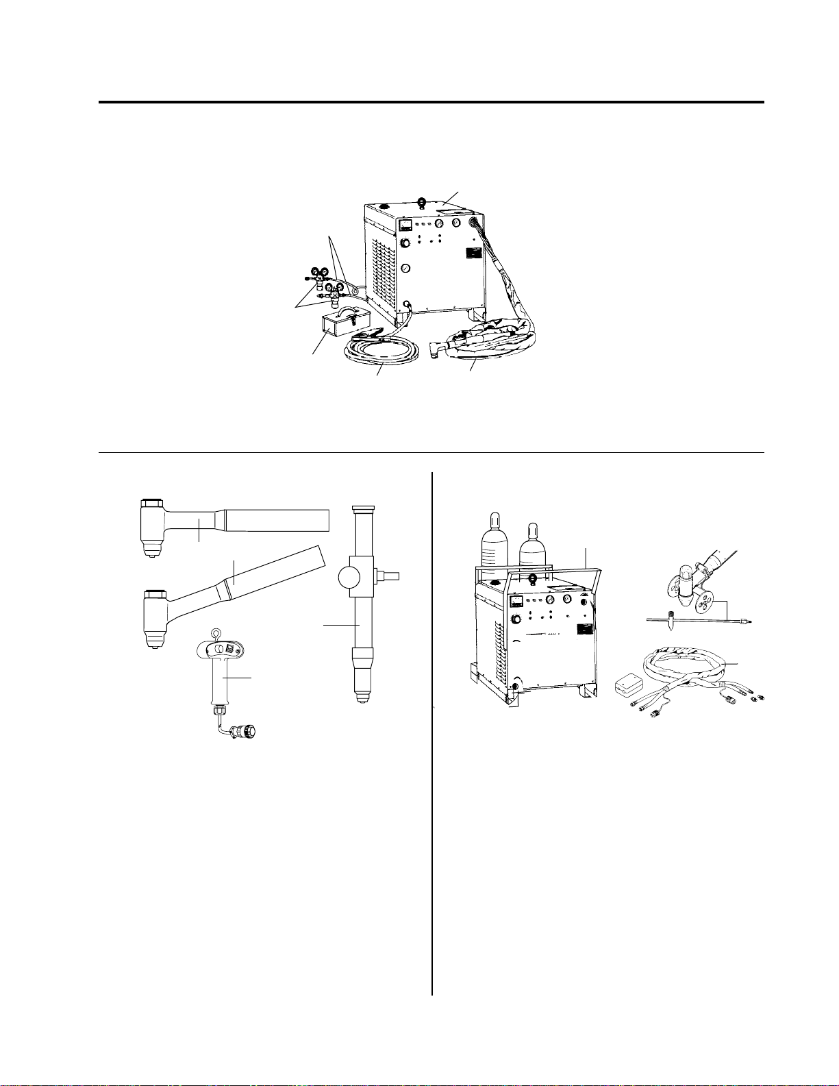
Gas Hoses
Gas
Regulators
Spare Parts
Kit
Work Cable
Torch and Leads
Figure 1-A Components of PAK 10 Cutting System
1
2
1
3
4
A-03290
Fig. 1-B Type 4B LO-AMP Gas Cooled Torches
1. 90° Hand cutting torch (PCH-4B 90°)
2. 70° Hand cutting torch (PCH-4B 70°)
3. Machine mounted cutting torch (PCM-4BT)
4. Remote control unit for machine mounted torch
10
K
A
rc P
al A
erm
Th
A-03291
Fig. 1-C Accessories
1. Cylinder Rack
2. Torch Guide & Circle Cutting Attachment
3. Leads Extension Package
2
3
Manual No. 0-0515 1 Specifications
Page 14
1.1. DESCRIPTION OF
EQUIPMENT
A complete PAK 10 system includes a PCH-4B hand
torch and/or PCM-4BT machine torch with 25 foot or
50 foot (7.62 m or 15.24 m) leads, a spare parts kit, a
PAK 10, gas supply, pressure regulators, 10 foot gas
supply hoses and a 25 foot work cable with clamp.
Three 4B torches are available (Figure 1-B): 90° hand
torch (1), 70° hand torch (2), and a machine mounted
torch (3). The 4BT machine mounted torch is controlled
by a remote control assembly (4, Figure 1-B) with an
ON/OFF switch and a remote current control. An initial supply of parts for the 4B is in the spare parts kit
(Figure 1-A).
PAK 10 UNIT
Power Input: 20 KVA, 50/60 Hertz, 3-phase in one of
the following standard voltage/amperage combinations:
1- 208/230/460 volts, 60/50/25 amps
2- 230/460/575 volts, 50/25/20 amps
3- 380/415/460 volts, 30/30/25 amps
4- 380/460/500 volts, 30/25/25 amps
5- 220/380/500 volts, 50/30/25 amps
6- 180/200/220 volts, 70/60/50 amps
Certain other special voltage combinations are avail-
able.
1.2. SPECIFICATIONS
TYPE 4B GAS COOLED TORCH
• Current Rating: 100 amperes maximum, DCSP , 80%
duty cycle
• Plasma Gas: Nitrogen (N2), 30 psi (2.2 kg/cm2), 15
SCFH (7.5 lpm); 65% Argon/35% Hydr ogen, 40 psi
(2.8 kg/cm2), 30 SCFH
• Secondary Gas: Carbon dioxide (C02), 50 psi (3.52
kg/cm2), 250 SCFH (125 lpm); compressed air, 50
psi (3.52 kg/cm2), 250 SCFH (125 lpm)
• Cutting Capacity (most metals): Maximum thickness- 1 inch (25.4 mm); production cutting- 5/8 inch
(15.9 mm); piercing- 3/4 inch (19 mm)
• Weight: Hand torch PCH-4B- 1-3/4 lbs. (0.79 kg);
Machine mounted torch PCM-4BT- 3 lbs. (1.36 kg)
without leads
C
• Rated Output: 100 amperes DC straight polarity
• Current Control: 50 to 100 amps continuously adjusted by feedback circuit
• Control Circuit: 24 volt AC
• Plasma and Secondary Gas Pressures: Controlled
by pressure regulator at gas supply
• Weight: 615 lbs. (279 kg)
• Dimensions: Width- 26 inches (66 cm); Depth- 36
inches (91 cm); Height- 24 inches (61 cm)
ACCESSORIES AVAILABLE:
• A cylinder rack (1, Figure 1-C) that holds two gas
cylinders
• A torch guide and cir cle cutting attachment (2, Figure 1-C)
• Torch lead extension packages to extend the torch
leads in increments of 25 or 50 feet (3, Figure 1-C)
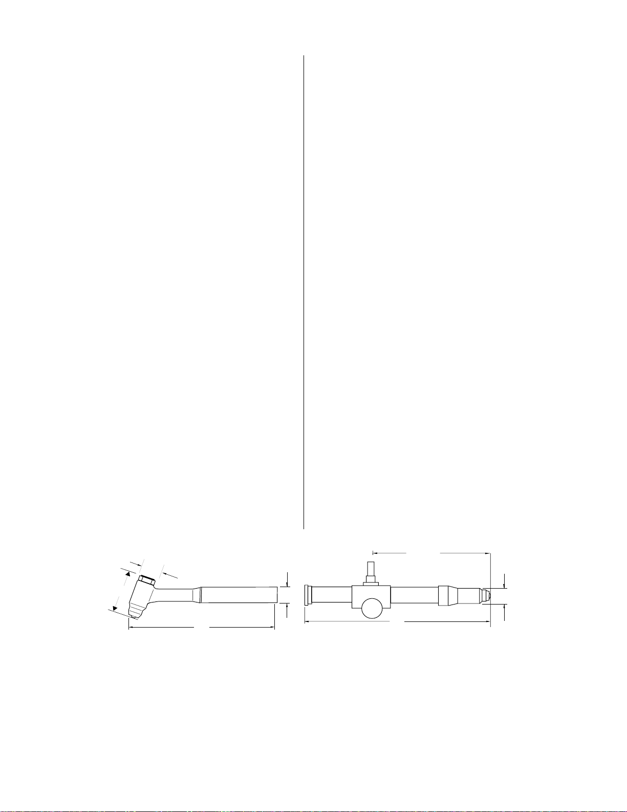
B MIN
C MAX
A-03292
B
A
D
A
D
TORCH DIMENSIONS
AB CD
PCH-4B (70°) 16.00” (406 mm) 3.98” (100 mm) 1.25” (32 mm) 1.32” (34 mm)
PCH-4B (90°) 15.25” (390 mm) 3.98” (100 mm) 1.25” (32 mm) 1.32” (34 mm)
PCM-4BT 18.38” (467 mm) 8.12” (206 mm) 16.00” (406 mm) 0.69” (17 mm)
Specifications 2 Manual No . 0-0515
Page 15
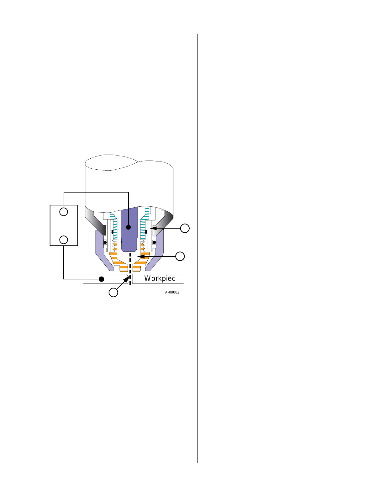
1.3. PLASMA CUTTING
1.4. THEORY OF OPERATION
Plasma is a gas which has been heated to an extremely
high temperature and ionized so that the gas becomes
electrically conductive. The plasma cutting process uses
this plasma to transfer an electric arc to the workpiece.
The metal to be cut is melted by the heat of the arc and
then blown away.
In a plasma torch, a cool gas such as nitrogen (N2) enters in Zone A, Figure 1-D. In Zone B a pilot arc between the electrode and the front of the tor ch heats and
ionizes the gas. An arc transfers to the workpiece
through a column of plasma gas in Zone C.
_
Power
Supply
A
+
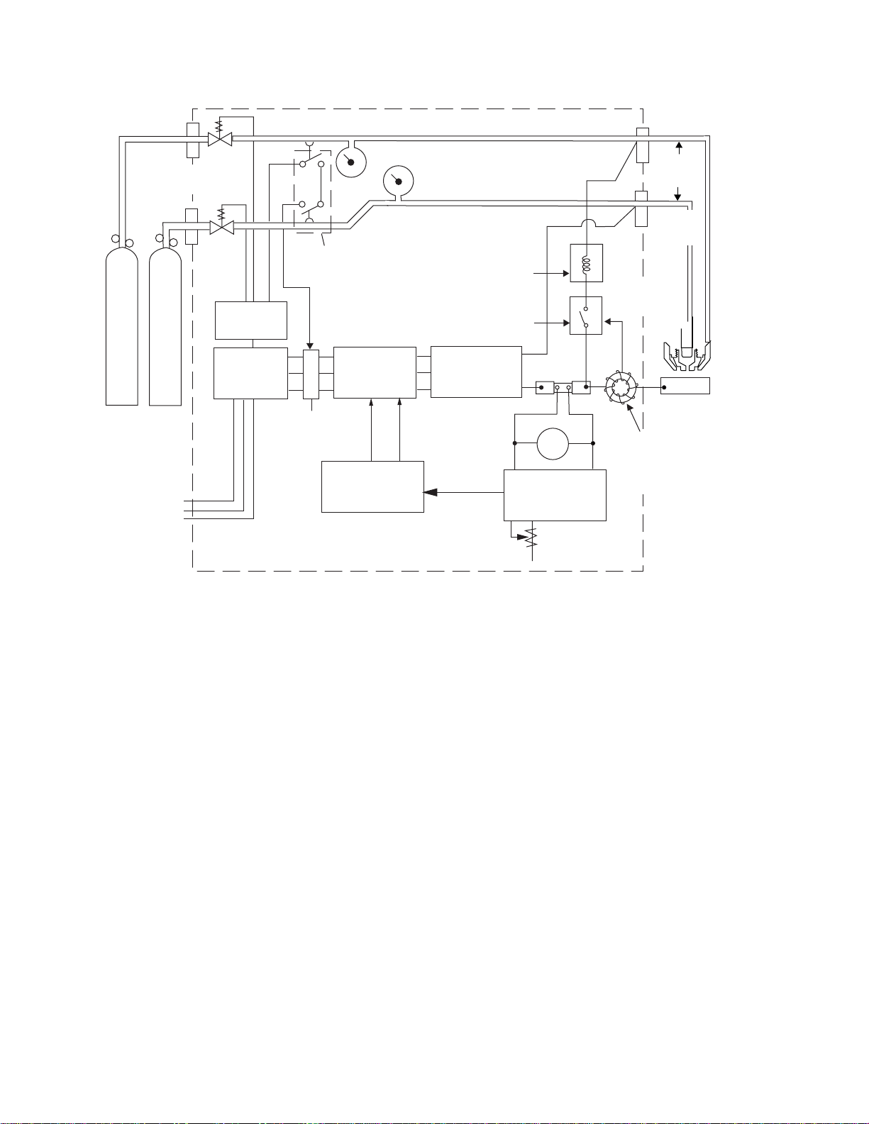
The main components of the PAK 10 cutting system
are illustrated in the block diagram (Figure 1-E) and
their function is summarized below.
PLASMA AND SECONDARY GASES
Plasma and secondary gases flow through the P AK unit
to the cutting torch at pressures set at the external r egulators. The pressure of each gas is indicated on the fr ont
panel gauges. Solenoid valves turn the gases on and
off. The gas pressure interlocks shut the system down
if the plasma gas pressure falls below 25 psi (1.7 bar) or
the secondary gas pressure drops below 30 psi (2.0 bar).
The plasma gas flows through the green/black lead,
around the electrode and gas distributor, and out
through the tip orifice.
The secondary gas flows through the red/yellow tor ch
lead, down the outside of the torch liner, through the
holes at the base of the liner and out around the plasma
arc.
PILOT ARC
When the torch is started, the pilot arc contactor closes
and an arc is established between the electrode and
cutting tip. The pilot arc makes a path for transferring
the main arc to the work.
B
Workpiece
C
Figure 1-D Plasma Torch Operation
Plasma torches deliver a high concentration of heat to
a very small area. The stiff, constricted plasma arc is
shown in Zone C. Direct current straight polarity is
used for plasma cutting, as shown in the illustration.
Plasma cutting torches use a secondary gas, which assists the high velocity plasma gas in blowing the molten metal out of the cut. This results in fast, clean, dross
(slag)-free cuts. In the PAK l0 system, the secondary
gas also cools the cutting torch. CO2 or compressed air ,
supplied by either a cylinder or plant air system, is normally used as the secondary gas.
A-00002
HIGH FREQUENCY
Because direct current alone is not sufficient to strike
and maintain the pilot arc, high frequency is superimposed on the direct current.
CUTTING ARC
The main bridge rectifier converts the 3-phase AC
power to DC power for the pilot and main cutting arcs.
The negative output is connected to the torch electrode
through the torch lead. The positive output is connected
to the workpiece (through the work cable) and, through
a contactor and resistor to the torch tip.
CURRENT CONTROL
The desired cutting current is set on the CURRENT
ADJUST knob. A control circuit stabilizes cutting current against fluctuations due to changes in line voltages, material thickness, torch standoff and travel
speed. Changing the amount of saturating current in
the reactor changes the amount of AC power supplied
to the main bridge rectifier. The amount of saturating
current is controlled by a comparator which compares
the actual cutting current to the amperage selector potentiometer setting.
Manual No. 0-0515 3 Specifications
Page 16
POS.
(RED/YEL)
GAS
SECONDARY
PLASMA
3-PHASE
AC POWER
SECONDARY GAS PRESS
SOLENOID
VALVES
GAS PRESSURE
INTERLOCK
CONTROL
CIRCUITS
GAS
POWER
TRANS-
FORMER
SATURABLE
REACTOR
MAIN
CONTACTOR
SCR CONTROL
BRIDGE
RECTIFIER
PAK 10 POWER SUPPLY AND CONTROL UNIT
PLASMA
GAS PRESS
PILOT ARC
HIGH FREQUENCY
PILOT ARC
CONTACTOR
MAIN BRIDGE
RECTIFIER
COMPARATOR
(-)
SHUNT
(+)
AMP
AMPERAGE
SELECTOR POT
TORCH
LEADS
NEG.
(GR/BLK)
CUTTING
TORCH
WORK
CURRENT
SENSING COIL
(TOROID
TRANSFORMER)
A-03293
Figure 1-E Block Diagram of PAK 10 Cutting System
Specifications 4 Manual No . 0-0515
Page 17
INSTALLATION
2.1 UNPACKING
The P AK 10 is skid-mounted and pr otected with a car ton and padding material to prevent damage in shipment. The casters, lifting eye, gas hoses, work cable,
torch, torch leads and miscellaneous parts are packed
separately.
One copy of the P AK 10 Instruction Manual, in a transparent plastic envelope, is packed in with the PAK 10
unit.
2
3
4
5
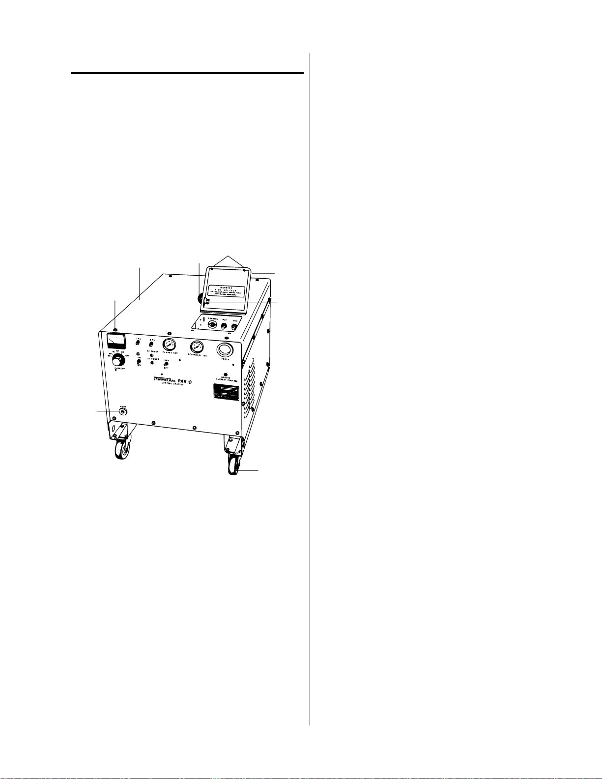
2.2 EQUIPMENT ASSEMBLY
After removing the carton, turn the lifting eye (3,
Fig. 2-A) all the way into the threaded socket on top
of the unit and tighten it securely. The lifting eye
may then be used to lift the unit for removal of the
skids and installation of the casters (7). If no crane
or hoist is available for lifting, a fork lift or jack may
be used. Use care so that the base of the unit will
not be damaged. Lift the unit and remove the two
skids which are secured to the base assembly with
four bolts and hex nuts. Install the two swivel casters (7) at the front of the unit using four 5/16-18 x
3/4 inch cap screws and four 5/16-18 locknuts in
each. Install the two fixed casters at the rear in the
same manner. Lower the unit onto the casters and
remove the lifting device.
1
8
A-03356
1. Washer-head cover screws
2. Cover Assembly
3. Lifting eye
4. Access door fasteners
5. Lead connection access door assembly
6. Interlock switch actuator
7. Casters
8. Work cable receptacle
6
7
Figure 2-A Power Supply and Control Unit with
Access Door Open
Manual No. 0-0515 5 Installation
Page 18

2.3 EQUIPMENT INSTALLATION
Select a clean, dry location with good ventilation and
adequate working space. Be sure that the air flow into
the unit (from underneath) and out the back is not obstructed. A source of 3 phase power and a source of
gases with pressure regulators ar e r equired.
Review PRECAUTIONS in the first section of this
manual to be sure that location meets all safety requirements.
Most users prefer nitrogen (N2) as the plasma gas and
carbon dioxide (C0
easy to obtain good quality cuts with this combination.
Argon/Hydrogen (Ar/H2) (65% argon-35% hydrogen)
is sometimes preferred as the plasma gas when cutting
1/2" to 1" thick aluminum to improve cut finish and
reduce smoke and fumes. Compressed air (free of dirt
and oil) may also be used as the secondary gas.
) as the secondary gas, since it is
2
3. Check for possible loose connections and damage
that may have occurred during shipment.
4. Check the transformer (Figure 2-C) to be sure that
it is set up for the available power . Three terminals
(Figure 2-C) are provided for each phase. As shown
in Figure 2-C, to connect the unit for 460 volts, the
three wires from the input terminals attach to the
three terminals marked 460. For other voltages, the
three wires are connected to the appropriately
marked terminals.
1
A-03357
Figure 2-B Internal Packing Material
NOTE
A typical 50 lb. CO2 cylinder is capable of delivering 35 SCFH on a continuous basis. Therefore, the manifolding of several CO2 cylinders
may be necessary to obtain the required torch flow
rate, depending on application and duty cycle.
Connect the unit as follows:
1. Remove the top of the unit as follows:
a. Remove the screws holding the cover.
b. Open the lead connection access door (5, Fig-
ure 2-A).
Voltage Connections Transformer
A-03358
Figure 2-C Transformer Voltage Connections
CAUTION
Input voltage of the available three phase power
source must correspond to one of the three operating voltages of the PAK 10. If not properly
connected, damage to the equipment may result.
c. Lift off the cover of the unit.
2. Remove the paper band (1, Figure 2-B) stapled
around the main terminal board.
Installation 6 Manual No . 0-0515
Page 19

5. Check the three phase power service to be used.
Recommended fuse or circuit breaker sizes are given
in Table 2-A.
Power
Transformer
1
2
3
4
5
6
Line
Voltages
Accepted
208
230
460
230
460
575
380
415
460
380
460
500
220
380
500
180
200
220
Fuse or
Circuit
Breaker
Amperes
80
60
30
60
30
25
40
40
30
40
30
30
60
40
30
90
80
60
Recommended
Minimum
Primary
Wire size *
4
6
10
6
10
10
8
10
10
8
10
10
6
8
10
4
6
6
* From t he Nati onal E l ec t ri c Code, 1978
7. Connect the gases to be used to the fittings on the
back of the unit (2 & 3, Fig. 2-E). Pressure regulators for use with PAK units and specifically calibrated for use with nitrogen (Cat. #9-2722), argon/
hydrogen (Cat. #9-3053), carbon dioxide (Cat. #9-
2759), and compressed air (Cat. #9-3022) are available from Thermal Dynamics. The gas supplies
must be equipped with adjustable pressure regulators capable of being set between 0 and 60 psi (0-4.1
bar) and of delivering 15 Standard Cubic Feet per
Hour (SCFH) (7 lpm) of N2 and 250 SCFH (118 lpm)
of C02 or compressed air.
2
Table 2-A Line Voltages, Circuit Protection &
Recommended Wire Size
NOTE
Larger wires may be requir ed if the length is over
25 feet.
6. With the primary power disconnect switch open,
connect the electrical ground and primary power
leads to the terminals on the upper right hand side
(facing the unit from the front.) Recommended wir e
sizes are given in Table 2-A. The leads are led
through the “INPUT” fitting in the back (1, Figure
2-E). A proper gr ound connection must be made to
the brass stud as shown (2, Figure 2-D). The other
leads are attached to terminals L1, L2, and L3 (1,
Figure 2-D).
WARNING
Do Not Turn on Power Until Step 10.
1
A-03359
1. Primary Lead T erminals
2. Ground T erminal
Figure 2-D Primary Lead Connections
Manual No. 0-0515 7 Installation
Page 20

10. The work cable (Figure 1-A) is equipped with a
twist-lock plug on one end and a work clamp on
the other . The plug fits into the work receptacle on
the front of the unit (8, Figure 2-A) and the clamp
attaches to the workpiece. The unit is now ready
1
INPUT
for operation.
SEC
2
PLASMA
3
4FU
5A
A-03360
1. INPUT cable bushing
2. SECondary gas connection fitting
3. PLASMA gas connection fitting
Figure 2-E Rear Panel Connections
8. Check the torch to see that it is properly assembled
(Refer to Section 4.1.).
a. Pass the torch leads and control wire through
the bushing on the front panel (5, Figure 2-F)
and connect them to the appropriate fittings.
1
4
6
l. Actuator for Interlock Switch (SW3)
2. Negative (-) torch lead fitting
3. Positive (+) torch lead fitting
4. Torch control switch receptacle
5. Tor ch lead insulating bushing
6. Remote current control jack
3
2
5
A-03361
b. If the torch is machine-mounted, the remote
control assembly plug must also be inserted in
the remote current contr ol jack.
Figure 2-F Torch Connection Access Door and
Panel
9. Re-install the cover of the unit (the leads access door
must be open). Start the sheet metal screws but do
not tighten them until the cover is lined up.
Carefully close the leads access door, making sure
that the switch actuator (1, Figure 2-F) enters its slot
and activates the interlock switch. When the cover
is properly positioned, tighten the screws.
W ARNING
Do Not Operate the Unit unless all parts of the
enclosure are in place. This is important for
proper cooling as well as safety.
Installation 8 Manual No . 0-0515
Page 21

OPERATION
50
2
AMPERES
D.C.
70
60
80
39
90
100
1FU
10A
ON
4
2FU
5A
AC POWER
DC POWER
1
OFF
MIN.
CURRENT
Thermal Arc PAK 10
8
Figure 3-A PAK 10 Control Unit Operating Controls
3.1 OPERATING CONTROLS
1. Current Adjust Knob
Select desired cutting current. Calibrated from Min.
up to 100 amps.
2. Ammeter (A)
Indicates amperage supplied to torch.
3. READY Indicator (LT3)
Amber light indicates that the ON/OFF switch is
ON and that lead connection access door is closed.
4. AC POWER Indicator (LT1)
Red light indicates that 3 phase AC power is being
supplied to the system.
5
60
0
4
34
8
0
2
5
20
1
6
bar
psi
100
PLASMA GAS
RUN
SET
CUTTING SYSTEM
7. RUN/SET Switch (SW2)
Move up to RUN position for torch operation. Move
down to SET position for purging gas lines and setting gas pressures with external regulators.
8. DC Power Indicator (LT2)
Red light indicates that main contactor (W) has
closed to supply current to the main bridge rectifier
and that cutting current is available.
9. ON/OFF Switch (SW1)
Move up to ON position to activate the control cir-
cuits. Move down to OFF position to deactivate
control circuits.
3.2 PRE-OPERATION SET-UP
7
6
60
0
4
34
8
0
0
2
5
2
1
6
bar
psi
100
SECONDARY GAS
CURRENT CONTROL
TORCH
REMOTE
A-03309
NOTE
Fan is on when this light is on.
This procedure should be followed at the beginning of
each shift:
5. PLASMA GAS
WARNING
Indicates pressure at which plasma gas is being supplied to the torch.
Check to be sure main disconnect switch is open.
6. SECONDARY GAS
Indicates pressure at which secondary gas is being
supplied to the torch.
l. Check the torch to be sure it has the proper compo-
nents and is adjusted correctly . (Refer to Section 4.1).
2. Close the main disconnect switch supplying 3- phase
power to the unit.
Manual No. 0-0515 9 Operation
Page 22

3. Turn the ON/OFF switch ON (9, Figure 3-A). The
amber “READY” light will come on. (If the gas supply is on, the gases will flow for two seconds).
4. Turn the RUN/SET switch to the SET position.
Open the plasma gas supply valve at the source.
Adjust the pressure regulator on the gas supply until
the plasma gas pressure reads 30 psi (2.0 bar).
5. Purge for approximately 3 minutes by letting the
plasma gas run. This will remove any condensed
moisture that may have accumulated in the torch
or leads while the system was shut down.
6. Open the secondary gas supply valve at the source.
Adjust the pressure regulator at the gas supply until pressure reads 50 psi (3.4 bar).
A-01917
7. Return the RUN/SET switch to the RUN position.
8. Set the current adjust knob (l, Figure 3-A) to the desired amperage level.
The system is now ready for operation. The torch is
controlled by the switch mounted on the torch handle
(or the remote control switch for a machine mounted
torch).
3.3 OPERATION
HAND TORCH OPERATION
W ARNING
Be sure the operator is equipped with proper
gloves, clothing, eye and ear protection and that
all precautions at the front of this manual have
been followed.
l. Hold the torch comfortably , as shown in Figur e 3-B.
One hand should be close to the head assembly and
the other hand positioned so that the thumb can conveniently operate the control switch. Position the
torch over the workpiece, resting the front of the
cup on the edge of the workpiece at the point where
the cut is to start. This will positively locate the line
of the cut.
Figure 3-B Positioning the Hand Torch for a Cut
2. Lower the welding helmet and lift the torch about
1/8" (3 mm) from the workpiece. Then press and
hold the control switch on the torch. After a two
second gas purge, the pilot arc will come on and
remain on until the main cutting arc is established,
at which point the pilot arc circuit switches off automatically.
A-03310
Figure 3-C Hand Cutting Over a Line on the
Workpiece
3. The cutting arc will remain on as long as the control
switch is held down unless the torch is withdrawn
from the work or the torch motion is too slow . If the
cutting arc is interrupted, the pilot arc will come on
again. It will remain on until the cutting arc is again
established or the control switch is released.
4. Cut with the torch about 1/8" to 1/4" (3 to 6 mm)
from the workpiece, as shown in Figure 3-C. Keep
the torch perpendicular to the work.
Operation 10 Manual No. 0-0515
Page 23

MACHINE T ORCH OPERA TION
When cutting with a machine torch, the torch must be
at right angles to the plate to obtain a clean, vertical
cut. Use a square, as shown in Figure 3-D, to align the
torch. It is good to start a cut at a slow speed and increase the speed to obtain the desired cut quality. Table
3-B gives typical cutting speeds for various materials
and material thicknesses.
Rack and
Pinion Mounting
Assembly
Square
Direction Of
Travel
A-00175
Workpiece
Figure 3-D Using a Square to Set Up the Machine
Torch
To start a cut at the plate edge, line up the torch away
from the plate, and press the control switch. The transferred cutting arc will then be established at the plate
edge. Adjust cutting speed for good cutting performance, as indicated by a trailing arc of approximately
5° (Figure 3-E). When cutting expanded metal the cutting arc and pilot arc will alternate establishing themselves automatically.
5˚ Approximately
A-01919
Figure 3-E A Good Cut Will Produce a Trailing
Arc of Approximately 5°
PIERCING
In some cutting operations, it may be desirable to start
the cut within the plate area rather than at the plate
edge. Piercing the plate is not recommended on plates
thicker than 3/4" (19 mm), based on a 5/16" (7 mm)
standoff, using a mechanized torch with a “running
start” and a maximum time to complete pierce of 3 seconds). Blowback from the piercing operation can
shorten the life of torch parts. All pier cing should therefore be done as quickly as possible with current set at
100 amperes.
A method called “running start” is r ecommended when
piercing with a machine mounted torch. Position the
torch off the cutting line a sufficient distance to allow
the pierce to be made before reaching the cutting line.
This allowance depends on the thickness of the material and the travel rate of the mechanized torch.
Manual No. 0-0515 11 Operation
Page 24

Starting Pierce
Continue Cut After Pierce
W ARNING
It is not enough to simply move the ON/OFF
switch on the unit to its OFF position when cutting operations have been completed. Always
open the power supply disconnect switch 5 minutes after the last cut is made.
A-01920
Figures 3-F and 3-G Piercing with Hand Torch
When using a hand torch, tip the torch slightly to pierce
so that blowback particles blow away from the torch
tip rather than directly into it, as shown in Figure 3-F.
Pierce off the cutting line and then continue the cut as
shown in Figure 3-G. Spatter and scale should be
cleaned from the shield cup and the tip as soon as possible. Spraying or dipping the shield cup in anti-spatter compound will minimize the amount of scale which
adheres to it.
NOTE
The suggestions listed below should be followed
in all cutting operations.
1. Wait five minutes before opening the main disconnect switch at shut down. This permits the cooling
fan to run to remove operating heat from the unit.
2. For maximum parts life, do not operate the pilot
arc any longer than necessary.
3. Remember that cutting current can be adjusted at
any time. Learn to change the current output to
provide a comfortable working speed for the particular material being cut.
4. Handle torch leads carefully and protect them from
damage.
5. In continuous cutting applications, it is often necessary to manifold 4 to 6 C02 cylinders together to
maintain pressure at 50 psi (3.4 bar).
COMMON CUTTING FAULTS
Listed below are common cutting problems followed
by probable causes of each. If problems ar e caused by
the P AK 10, r efer to the Trouble Shooting Section (Section 4).
1. Insufficient Penetration
a. Cutting speed too high
b. Current too low
2. Main Arc Extinguishes
a. Cutting speed too low
b. Standoff too high
3. Dross Formation
a. Improper gas pressure or mixture
b. Improper cutting speed (Refer to Table 3-B)
c. Faulty electrode or tip
4. Burned-Out Tips
a. High cutting current
b. Damaged or loose cutting tip
c. Contact with work
d. Heavy spatter
e. Low plasma gas pressure
f. Back cap not tight
g. Spring not correctly installed
6. Because of the swirl of plasma gas in the torch, the
right hand side of the cut (in relation to torch travel)
is normally of better quality. Reverse swirl tips are
available for mirror image cutting.
FREQUENTLY REVIEW THE SAFETY PRECAUTIONS GIVEN AT THE FRONT OF THIS MANUAL.
Operation 12 Manual No. 0-0515
Page 25

3.4 CUTTING CURRENT AND SPEED SELECTION
The desired cutting current and the speed at which the
torch is moved along the line of the cut depend on the
thickness and composition of the workpiece. In hand
cutting, the speed is usually determined by how fast
the operator can comfortably and accurately follow the
line of the cut.
Most operators find that at speeds much above 30 ipm
it is difficult to accurately follow the line of the cut. For
machine cutting, faster speeds are often used. Refer to
Table 3-B.
This chart is intended as a guide to determining approximate conditions for making good quality cuts in
various thicknesses of material. Slower speeds may be
obtained on thin sections by reducing the current to
between 50 and 100 amperes.
The speeds shown are typical for cutting at 100 amperes using the 8-4153 (0.059) tip.
Plasma Gas - N2 at 30 psi (2.0 bar), 15 SCFH (7.1 lpm)
Secondary Gas - CO2 or Compressed Air at 50 psi (3.4
bar), 250 SCFH (125.0 lpm)
NOTE
This information represents our best judgment
but Thermal Dynamics Corporation assumes no
liability for its use.
INCHES/MINUTE (METERS/MINUTE)
THICKNESS 1/8" (3.2 mm) 1/4" (6.4 mm) 1/2" (12.7 mm) 3/4' (19 mm) 1" (25.4 mm)
Stainless
Steel
Alum i num 125 (3.18) 90 (2.29) 34 (0.86) 25 (0. 63) 12 (0. 30)
Carbon
Steel
Note: S peeds for Argon/ Hy drogen Pl asma Gas at 40 psi (2.7 bar), 30 S CFH (14.2 l pm )
with t he 8-4170 LO-AM P t i p at 100 amps are s l ightly faster. A rgon/Hy drogen is not
100 (2.54) 60 (1.52) 24 (0.61) 20 (0.50) 10 (0. 25)
75 (1.90) 45 (1.15) 24 (0. 61) 18 (0.46) 9 (0.23)
recomm ended for cut t i ng carbon st eel.
Table 3-B Recommended Cutting Speeds
Manual No. 0-0515 13 Operation
Page 26

PAK 10 - SEQUENCE OF OPERATION
System OFF
ACTION
1. Close external disconnect switch.
Red AC POWER indicator ON.
2. ON/OFF switch to ON.
RESULT
1. Amber ready indicator ON.
2. Coolant pressure switch closes.
3. Gases flow.
After two seconds:
4. Gas flow stops.
ACTION
1. RUN/SET switch to SET.
RESULT
1. Gas valves open, gases flow to
purge system and allow setting
of pressures.
2. Power circuits disabled.
ACTION
1. Lower helmet and close control switch on torch (or remote
control assembly).
RESULT
1. Gases flow and gas pressure switches close.
2. Main contactor closes. Red DC indicator ON.
After two seconds:
3. High frequency ON
4. Pilot arc relay closes.
5. Pilot arc comes ON.
System READY
ACTION
1. RUN/SET switch to RUN.
2. Select cutting amps with
CURRENT knob.
RESULT
1. Gas flow stops.
2. Power circuits ready.
PILOT ARC
ACTION
1. Torch moved away from workpiece,
or workpiece burns away under
torch.
RESULT
1. Cutting Arc stops.
2. Current sensing circuit turns ON high
frequency and pilot arc.
A-01892
ACTION
1. Torch brought close (within 1/4 inch)
to workpiece.
RESULT
1. Arc transfers to workpiece to
establish Cutting Arc.
2. Current sensing circuit turns OFF
pilot arc and high frequency.
Cutting Arc
NOTE:
To shut down system, allow fan and pump to run for
five minutes and then move On/OFF switch to OFF. Be
sure to open external disconnect switch.
ACTION
1. Open control switch on torch (or
remote control assembly)
RESULT
1. Red DC power indicator OFF.
2. Pilot arc stops.
After two seconds:
3. Gas flow stops.
System READY
NOTE
To shut down system, move ON-OFF switch to OFF. Wait 5 minutes to allow fan to remove heat from unit.
Then open external disconnect switch.
Manual No. 0-0515 14 Operation
Page 27

SERVICE
Torch Disassembly and Inspection
The Service Section is divided into six parts:
4.1 Torch Maintenance
4.2 Torch Leads and Leads Extension Packages
4.3 PAK Unit Maintenance
4.4 Gas Pressure Regulators
4.5 Trouble Shooting Guide
4.6 Test Procedur es
4.1 TORCH MAINTENANCE
The 4B and 4BT torch parts are interchangeable with
two exceptions. First of all, the 4BT collet is a different
design than the 4B. This is so that the collet can be
installed from the front of the torch. By installing the
collet from the front of the torch the back cap is eliminated in the 4BT design. These differences require
slightly different disassembly and assembly procedur es.
When a different pr ocedure is required, the tor ch model
will be specified, otherwise the step applies to both torch
models.
WARNING
Disconnect primary power before disassembling
the torch.
Disassemble the torch parts as follows:
1. Pull off the shield cup (1) and inspect it for damage.
Wipe it clean, or replace it if it appears to be damaged.
2. Use the tip wrench (17) to unscrew the tip (2). Check
the tip for wear as indicated by an elongated or oversize hole. Make sure that the tip is clean and that
threads have not been damaged. Replace the tip if
necessary.
3. Lift out the gas distributor (3). Remove the electrode (7) and check the end for pitting.
1
1
2
3
15
4
5
6
5
267
4
3
Figure 4-A Plasma Cutting Torch (PCH/M-4B), Exploded View
1. Shield Cup
2. Tip
3. Gas Distributor
4. Liner (includes 9-2960 O-ring)
5. O-ring (included with Liner)
6. Sleeve
7. Electrode
8. O-ring (included with Shield Cup)
9. Gasket
13
A-03311
14
10b
11
12
8
9
10a
16
12
13
9
8
17
7
10. Head Assembly:
a) PCH-4B
b) PCM-4BT
11. O-Ring: PCH-4B
12. Collet with 8-0525 O-Ring
13. Spring
14. Back Cap: PCH-4B
15. Liner Wrench
16. Tip W r ench
17. Collet Wrench: PCM-4BT
Manual No. 0-0515 15 Service
Page 28

If the end of the electrode is badly pitted (cavity
almost covers diameter) then that end of the electrode should no longer be used.
The electrode may then be reversed. When both
ends are pitted, the electrode should be replaced.
Do not attempt to repoint the electrode.
NOTE
Torch Assembly
WARNING
Disconnect primary power before assembling the
torch.
Remove the liner assembly (4) and sleeve (6), in
accordance with the following step, only if either appears to be damaged and requires replacement.
4. Remove the liner assembly (4) with the liner wrench
(16). After unscrewing the liner, slip out the sleeve
(6).
5. PCH-4B: Unscrew the back cap (14) and remove the
spring assembly (13) and collet assembly (12).
6. PCM-4BT: The collet (12) is removed by sliding the
collet wrench (17) into the torch cavity and unscr ewing it from the torch.
NOTE
The spring assembly (13) should come out with
the collet. Care must be taken not to lose this
spring.
6
1
3
1. PCM-4BT: Insert the spring assembly (13) into the
collet (12) and install the collet in the torch cavity.
Tighten down with collet wrench (17).
2. Insert the sleeve (6) in the liner (4). The sleeve should
be clean and dry and may be either end up.
3. O-ring (5) should be lightly lubricated with O-ring
lubricant (Cat. No. 8-4025) and installed just past
the threads on the liner. Install the liner (4) in the
torch using the liner wrench (16).
4. PCH-4B: Insert the spring assembly (13) in the collet
(12) and install the collet in the back of the torch
with the end with the O-ring toward the front.
5. PCH-4B: Check the O-ring (11) that seals the back
cap to be sure it is lightly lubricated (Cat. No. 8-
4025) and in good condition.
4
5
2
1
PCH-4B HAND TORCH
7
PCM-4B MACHINE TORCH
8
9
10
A-03312
Figure 4-B Hand and Machine Torch Heads, Exploded View
1. Head
2. Heat Shield
3. Handle
4. Torch Switch
5. Torch Switch Sheath
6. Back cap
7. Nut
8. Insulating Sleeve
9. Mounting tube
10. Pinion assembly
Service 16 Manual No. 0-0515
Page 29

6. PCH-4B: Install the back cap (14) and tighten it securely.
CAUTION
Use care to see that the back cap is turned all the
way down to hold the collet (12) securely. On
the machine torches this cap goes down inside
and may seem tight, but still may not be holding
the collet tightly. Arcing may result, welding
the collet to the torch and causing irreparable
damage.
7. Insert the electrode (7) in the torch from the front.
Push it back against the spring to make sure it slides
freely back and forth.
8. Install a gas distributor (3) in the tip (2) and install
the tip in the front of the torch. Tighten it securely
with a tip wrench (16).
9. Install a gasket (9) and two O-rings (8) on the front
of the torch. The O-rings must be lubricated with
O-ring lubricant (Cat. No. 8-4025).
10. Install the cup (1) on the front of the torch.
The torch is now ready for operation.
Use a ferrule (1) to secure the hose to the fitting or lock
the hose in place with a twisted wire. If a ferrule is
used, crimp (1) in place with 1/2 inch diameter crimping dies, Scovill No. 39 or equal. Crimp (1a) in place
with 5/8 inch diameter crimping dies, Scovill No. 34
or equal.
2
4
5
6
A-03313
1a
1
3
1a
1
Figure 4-C Torch Lead Fittings
4.2 TORCH LEADS AND LEADS
EXTENSION PACKAGES
Torch Leads Replacement
T o r eplace the tor ch leads on a hand torch separate the
leads covering from the torch handle by pulling the
torch switch sheath (5, Fig. 4-B) back over itself to expose where the leads covering is secured to the handle.
Remove the tape securing the covering to the handle.
Pull the covering away from the handle and disconnect the switch from the leads package. Unscrew the
handle from the torch and slide back to expose the leads
connections. Leads are connected to the appropriate
fittings on the torch in accordance with the color coding-red/yellow for secondary gas and green/black for
plasma gas. A plastic insulator is located between the
fittings in the handle.
The fittings (Figure 4-C) on the ends of the torch leads
may be replaced. Cut the hose close to the old fitting.
Cut the wire inside the hose and discard the old fitting.
Attach new fittings to the wire by crimping the tube,
on the fitting, onto the wire. Crimp the tube with a
Stakon size C crimping tool. It is important to crimp
the tube all the way back to the first hole to ensure adequate gas passage.
l. Ferrule
2. Fitting, console end (-)
3 Nut, console end (+)
4. Fitting, console end (+)
5. Fitting, torch end (+)
6. Fitting, torch end (-)
LEADS EXTENSION PACKAGES
Leads extension packages are available to extend the
torch leads in increments of 25 and 50 feet. The packages are available as follows:
PCH-4B 25': Cat. No. 4-2739 50': Cat. No. 4-2740
PCM-4BT 25': Cat. No. 4-2741 50': Cat. No. 4-2742
1. Lead Adapter
2. Insulator
3. Leads (25' or 50')
2
3
A-03314
1
Figure 4-D Leads Extension Package
Manual No. 0-0515 17 Service
Page 30

WARNING
4.4 GAS PRESSURE REGULATORS
Disconnect primary power before installing the
leads extension package. Do not turn on primary power to unit until all connections are
made and insulators are in place.
The leads that are furnished with the extension packages are the same as standard leads with the exception
of the control switch leads for the hand torch. On the
extension package the control switch leads terminate
in a receptacle for the 2 prong “Twist-Loc” plug. The
standard leads have a square plastic connector that
mates with the one on the torch leads.
NOTE
For leads extension over 100 feet the two-second
gas purge is not adequate. Replacement of TD2
Relay (Catalog No. 9-2694) with a Catalog No.
9-3528 Relay will increase the purge time to ten
seconds.
4.3 PAK UNIT MAINTENANCE
The only routine maintenance required for the PAK 10
system is a thorough cleaning and inspection of the unit.
This should be done on a regular basis, the frequency
depending on the amount of usage and the environment in which the unit is operated.
The Thermal Arc gas pressure regulators provide a
means of conveniently selecting and maintaining the
required working pressures of the gases. The regulator will hold this pressure constant. Inlet pressure is
reduced in one step to the working pressure by means
of a pressure balanced poppet valve controlled by a
spring loaded piston in a low pressure chamber . A lar ge
adjusting knob (6, Figure 4-E) provides for adjusting
spring pressure against the piston. A sinter ed stainless
steel filter , in the inlet connector (1), prevents dirt from
entering the regulator mechanism.
No regular maintenance of the gas pressure r egulators
is required, except an occasional lubrication of the adjusting screw thread and on its end, where it contacts
the adjusting spring. Lubricant is available from Thermal Dynamics for this purpose (Catalog No. 9-2871).
Replaceable parts in the regulator include the pressure
gauges, the O-ring seals on the piston and above the
poppet valve, and the poppet valve. (See Assembly
Parts List Fig. 5-10 for replacement parts).
CAUTION
Do not attempt to remove the sintered metal filter in the inlet connection. This is not a serviceable item.
WARNING
Removing the cover of a PAK 10 with a Running Gear also removes the retaining chains
making the gas cylinder free-standing. This cylinder must be restrained by some temporary
means until the cover and retaining bar are replaced and the retaining chains reconnected.
T o clean the P AK unit, first make sur e that the power is
disconnected and AC Power Light (LT1) off. Remove
the cover and side panels of the unit and blow out any
accumulated dirt and dust with compressed air. The
unit should also be wiped clean. If necessary, solvents
that are recommended for cleaning electrical apparatus may be used.
While the covers are off, inspect the wiring in the unit,
looking for any frayed wires or loose connections that
should be corrected. When cleaning the unit pay particular attention to the area around the high fr equency
spark gap points since accumulated dirt in that area
can weaken the high frequency starting current.
Service 18 Manual No. 0-0515
Page 31

2
3
4
WARNING
Removing the cover of a PAK 10 with a Running Gear also removes the retaining Chains
making the gas cylinders free standing. These
cylinders must be restrained by some temporary
1
means until the cover and the retaining bar are
replaced and the retaining chains reconnected.
When the external disconnect switch is closed, the red
5
“AC POWER” light goes on and the fan starts. When
the ON/OFF switch goes ON, the amber “READY”
light goes on and the gases flow for two seconds. If
this does not happen, check as follows:
A-01894
6
A. No “AC POWER” light
1. Blown fuse or open circuit breaker at disconnect
Figure 4-E Components of Gas Pressure
Regulator
1. Inlet Connection
2. Inlet Pressure Gauge
3. Safety Valve
4. Working Pr essur e Gauge
5. Hose Connection
6. Adjusting Knob
4.5 TROUBLE SHOOTING GUIDE
If the unit malfunctions, the following table will be helpful in correcting the problem. Since the malfunction
may be due to a faulty connection rather than a faulty
component, be sure to check all connections to a component that appears to be malfunctioning.
The trouble shooting table is arranged in the normal
operating sequence of the unit for easy reference. Each
problem has listed next to it the possible causes and
the remedy.
In some cases the remedy is too complex to fit in the
table, in which case there is a reference to one of the
TEST PROCEDURES.
a. Replace fuse or reset breaker.
B. No “READY” Light
1. Door interlock switch (LS) not actuated
a. Check switch and actuator tab.
2. Blown fuse 2FU
a. Check fuse.
3. Main transformer overheated
a. Allow unit to cool down.
C. Gases do not flow when READY light comes on
1. Gas supply not on
a. Open valves.
D. Gases flow more than 2 seconds
1. RUN/SET Switch in SET position
a. Switch to RUN.
2. Faulty post flow time delay (TD1)
a. Check time delay TD1 (See A, Test Proce-
dures).
E. Cannot set desired gas pressure
1. Empty cylinder
a. Replace.
2. Faulty regulator
a. Repair or replace.
3. Faulty solenoid valve
a. Replace.
Manual No. 0-0515 19 Service
Page 32

When the torch switch is pressed, the gas and red “DC
POWER” light should come on. If this does not happen, check as follows:
F. Gas does not flow when torch switch pressed
1. Torch switch not connected
a. Check wires to plug, switch, and receptacle.
2. Torch switch not closing
a. Check for continuity when pressed.
3. Faulty control relay 1CR
a. Check relay (See C, Test Procedures).
4. No 24 volt power
3. Shorted torch leads
a. Repair or Replace.
J. No spark can be seen in torch
1. High frequency points shorted
a. Clean and dry area around high frequency
points, adjust gap to 0.015".
2. Shorted capacitor C-1
a. Check (See F, Test Procedures).
3. CSR closing with no cut
a. Check for shorted toroid (See G, Test Proce-
dures). Replace CSR.
a. Check output of transformer T2 (See B, Test
Procedures).
G. No red “DC POWER” light
1. Pressure switch PS1 or PS2 not satisfied
a. Check and adjust gas pressure regulator
Plasma should be 30 psi (2.0 bar), secondary
should be 50 psi (3.4 bar).
2. Faulty main contactor (W)
a. Check contactor (See D, Test Procedur es).
3. Failed diodes in main rectifier
a. Check diodes (see E, Test Procedur es).
The Pilot Arc should start two seconds after the red
“DC Power” light comes on. If it does not, check the
torch parts to make sure they are in good condition and
properly assembled. Check to see if:
1. PCR relay energizes at the time the pilot arc should
start (two seconds after pressing switch).
2. There is any reading of the ammeter (normal Pilot
Arc is 8 to 12 amps).
3. There is any light visible inside the torch.
H. No PCR movement two seconds after torch
switch pressed
1. Faulty time delay TD2
a. Check TD2 (See A, Test Procedures).
I. No pilot but ammeter reads 40 amps
1. Torch assembled without gas distributor
a. Assemble torch with correct parts (See Sec-
tion 4.1.)
4. Broken conductor in torch leads
a. Repair or replace.
5. High frequency transformer T3 failed
a. Check (See H, Test Procedures).
6. Dirty or wet torch leads
a. Clean and dry leads.
K. Spark in torch but no pilot (ammeter reads 0)
1. Insufficient DC voltage
a. Check for 205 volts open circuit (See J, Test
Procedures).
2. Pilot contactor (PCR) not closing
a. Check for DC at torch (See L, Test Proce-
dures).
3. Pilot resistor failed
a. Check resistor (See K, Test Pr ocedures).
The Cutting Arc should start as soon as the tor ch, with
the pilot arc running, is brought to within about 3/8
inch (10 mm) of the workpiece. If it does not, check:
L. No cutting arc
1. Work cable not connected
a. Connect.
2. One leg of 3-phase primary out
a. Check all 3 input phases for voltage.
3. One leg of main contactor (W) not closing
a. Check voltage at diodes (See M, Test Proce-
dures).
2. Shorted torch head
a. Replace.
Service 20 Manual No. 0-0515
Page 33

4. Current control cir cuit inoperative (A cutting ar c can
be established on very thin material if the torch is
held very close)
a. See next section (Problem M).
Once the cutting arc is established, the cutting current
should be equal to the setting of the CURRENT adjust
knob (unless the remote current control is in use). If it
is not, there is a problem in the current regulating circuit as follows:
M. Unit only puts out minimum current
1. Fuse 1FU blown
a. Replace.
2. Fuse blows again
a. Check diodes, varistor and SCR’s in control
bridge (See N & V, Test Procedures).
3. Reactor disconnected
a. Check (See P , Test Procedures).
4. Printed circuit card failed
a. Check (See Q, Test Procedur es).
5. Potentiometer failed
a. Check (See 0, Test Procedur es).
6. T5 transformer failed.
a. Check for 12VAC at each sec. coil.
N. Unit only puts out max. current-100+ A
1. Pilot arc remains on during cut
a. Check CSR circuit (See R, Test Pr ocedures).
2. Shunt disconnected
a. Check (See T, Test Procedures).
3. Printed circuit card failed
Q. Short torch parts life
1. Pilot arc remains on during cut
a. Check CSR circuit (See R, Test Pr ocedures).
2. No pre-purge gas flow
a. Check time delay TD2.
3. No post purge gas flow
a. Check time delay TD1.
4. Misuse of torch
a. Use torch within ratings for current and work
thickness.
R. Arcing in collet area
1. Back cap not tight
a. Replace collet and tighten cap securely .
2. Dirt in collet area
a. Clean electrode, collet and collet seating area.
S. Discolored electrode
1. Gas hoses switched
a. Check.
2. Contaminated gas
a. Check plasma gas system for leaks.
3. No pre/post purge
a. Check TD1 and TD2.
4.6 TEST PROCEDURES
The following tests are suggested for specific problems
listed in the preceding trouble shooting chart. The letter designations correspond to those listed in the “Remedy” section of the trouble shooting chart.
a. Check P .C. card (See Q, Test Procedures).
O. Unit can only put out about 70 amps maximum
1. P .C. card failed
a. Check P.C. Card.
2. One SCR failed
a. Check SCR’s (See U, Test Procedur es).
P. Unit output does not match potentiometer
setting
1. Remote Control resistance open
a. Check circuit (See S, Test Pr ocedures).
Manual No. 0-0515 21 Service
Several of these tests involve voltage measurements that must be made with power on. In order to make these measurements, the leads access door interlock switch must be propped closed
or by-passed. Use extreme care when making
these tests and be sure to return the interlock
switch to proper operation after work is completed.
WARNING
Page 34

T ests requiring voltage measurements ar e marked with
the warning symbol:
All other tests are to be made with the primary power
to the machine turned off.
NOTE
A. The two time delay relays, TD1 and TD2, are inter-
changeable and can normally be checked by swapping them. They are the “delay on operate” type
with a fixed 2 second delay.
B. The 24 volt transformer and switch circuit can be
checked with an AC voltmeter. The meter probes
should be on J1-2 and J1-6 which are pin connections on the printed circuit card that holds the relays. These pin connections can be located by finding J-1 and counting from the four corner pins which
are numbered as shown.
Harness Connector
J1
C. Relay 1CR has a 24 volt AC coil. The coil resistance
should be approximately 80 ohms measured from
pin A to pin B (on bottom of relay).
Bottom Of
Relay 1CR
1
45
7
AB
Pin A Pin B
2
8
A-01900
3
6
9
123456789101112131415
16
Pin 2
Pin 6
A-01899
Measure 24 volts AC her e when torch switch is closed.
D. To check the main contactor remove the left side
panel of the machine. The contactor should close
when 115 volt AC is applied to lines 1 and 15 (when
the torch switch is closed). At this time, 150 volt 3
phase power should be present at lines 33, 34, and
35. (150 volt 3 phase power should always be
present at lines 38, 39, and 40 when the primary
power is turned on).
E. A “quick check” can be made on the main diodes
without removing them from the circuit as follows:
Using an ohmmeter with the RX1 or RX10 scale,
measure the resistance of each diode in both directions. The readings should differ by at least a factor
of 10. If they do not differ (both high or both low)
the diode has failed and must be replaced. If a diode fails it is important to check several things to
make sure that the replacement diode will not fail.
There are four potential causes of diode failures:
1. An in-rush current surge is the most probable
cause of main diode failure. The in-rush surge
is absorbed by capacitor C-5 and resistor R-1 in
series with each other across the output of the
bridge rectifier. The capacitor and resistor, as
well as the wires connecting them to the circuit,
should be completely checked in any case of
diode problems. The capacitor is a polarized
capacitor , and it is important to be sure that the
side marked + is connected to the positive side
of the circuit.
Service 22 Manual No. 0-0515
Page 35

2. High frequency protection for the diodes is pr ovided by capacitors C-2, C-3, and C-4 which are
installed between each side of the bridge rectifier and ground, and across the output of the
bridge rectifier . These capacitors and their connections should be checked.
K. The pilot arc resistor is located horizontally at the
back of the unit. It should read 3.5 ohms.
3. Overheating of the diode can occur if air flow
over the heat sink is inadequate or if the diode
is not properly fastened to the heat sink. Check
to see that the diodes are torqued to 125 inch
pounds (15 Nm) and that electrically conductive heat sink compound (this is a white grease)
is present between the diode and heat sink. Also
check for normal operation of the fan and to be
sure that the air passages into and out of the
unit are not obstructed.
4. The diode that was faulty at the time of manufacture is difficult to diagnose. This usually fails
during the first few hours of operation. Before
deciding that this was the case, be sure to check
out the other three possibilities.
F. To check the high frequency capacitor, it is neces-
sary to try to start the torch. The spark between the
spark gap points should be bright blue. If the spark
appears to be weak or nonexistent, disconnect the
wire between the spark gap and the capacitor and
try to start the torch again. If the spark is stronger
with this wire disconnected, the high frequency capacitor is faulty and must be replaced.
G. To check the toroid coil, measure the AC voltage
supplied to relay CSR (measured between pins J114 to J2-15). This voltage is measured with the torch
switch closed (2 seconds after closing the switch)
and should read approximately 40 VAC. If it reads
115 VAC the toroid coil winding(s) is shorted and
the toroid must be replaced.
H. The high frequency transformer has too much volt-
age (6000 volts AC) to check under power. The resistance of the primary coil should be 5 ohms and
the resistance of the secondary coil should be about
20 K ohms.
L. To check for DC voltage at the torch leads it is nec-
essary to disconnect the high frequency first to avoid
damage to the voltmeter. The 115 volt primary to
the high frequency transformer is connected through
two push-on connectors at the high frequency transformer (near the front panel of the unit). These are
lines 1 and 18, and the high frequency can be disconnected by removing one of these wires.
Once the high frequency is disconnected, the torch
switch should be closed. 205 volts DC will immediately be present between the negative lead and
ground. After 2 seconds r elay PCR should close and
205 volts can then be measured between the negative lead and the positive lead. If no voltage is
present check the PCR coil and contacts.
M. The 3 phase AC input to the main bridge rectifier is
150 volts. This can be measured at the top of the
main bridge rectifier where the diode pigtails join
together (lines 30, 31, and 32) at any time that the
DC power light is on.
N. Locate the control bridge near the top of the unit (2
SCR’s and 3 diodes on three aluminum heat sinks,
Item No. 2 & 3, Fig. 5-3). Disconnect the multi-conductor plug next to this component. Using an ohmmeter with the RX10 scale, all three diodes should
be checked for high resistance in one direction and
low resistance in the other direction. If diode D8
(middle heatsink) is shorted see T below . The SCR’s
should read a high resistance in both directions.
(This is a “quick check” - diodes and SCR’s may be
checked as described in test F.)
O. Remove the current regulating printed circuit card
(Item No. 7, Fig. 5-2) from the machine and measure the resistance between the 3rd and 7th pins on
the receptacle (counting from the bottom). This
should read 0 ohms with the dial set at “MIN” and
increase smoothly to 5,000 ohms as the dial is rotated to “MAX”.
P. With the control bridge (see N above) connected to
J. The open circuit voltage can be checked between
the two heat sinks of the main bridge rectifier . This
should be 205 volts DC.
Manual No. 0-0515 23 Service
the circuit, measure the r esistance across the diode
on the center heat sink in both directions. It should
read about 5 ohms both ways.
Page 36

Q. The best way to check the printed circuit control
card is to replace it with one known to be good. The
same card is used in the PAK 10, 22, 44 and 350.
R. Watch the high frequency points during a cut. If
the high frequency remains on, check the r esistance
of the toroid coil (See test G) and of the relay CSR.
The coil of relay CSR should read about 3K ohms
measured from pin A to pin B (bottom view same
as time delay - See test C).
S. The remote control jack has a switch and a 10,000
ohm resistor which is switched out of the circuit
when the remote control potentiometer is plugged
in. Performing Test O checks that this resistor is
properly connected.
T. Remove the printed circuit card from the machine
and check for continuity from the 1st and 6th pins
on the receptacle (counting as in O above). If there
is no continuity , the shunt is not properly connected.
U. W ith a soldering pencil, disconnect the “pigtail” lead
to the SCR’s one at a time. When more than one
wire is connected to the pigtail, the two wires should
be connected to each other. Operate the unit with
one and then the other SCR disconnected and note
the maximum amperage. The output will remain
unchanged when the bad SCR is disconnected and
will drop to minimum when the good SCR is disconnected.
V. A bad varistor (VR) is difficult to detect by itself. It
will, however, cause the D8 diode on the control
bridge to short and burn out. If this happens, or if
the varistor looks burnt, replace both.
This concludes the test procedures.
Service 24 Manual No. 0-0515
Page 37

PARTS LISTS
General Arrangement
The Assembly Parts List consists of illustrated Parts
Lists of the following:
• Complete PAK 10 Cutting System
• Equipment Board Assembly
• Control P.C. Board Assembly
• Control Bridge & Main Bridge Assemblies
• Torch Connection Panel Assembly
• Pilot Resistor and Rear Panel Assembly
• Front Panel Components Assembly
• Base Components Assembly
• Leads and Leads Fittings, Remote Control Assem
bly, Leads Extensions, Torch Guide & Circle Cut
ting Attachment
• Series 4B Gas Cooled Torches
• Gas Pressure Regulators
An item number in parentheses indicates the item is
located behind the item pointed to. An asterisk beside
the item number indicates the part is a main assembly,
not a component. Parts listed without item numbers
are not illustrated, but may be ordered by the catalog
number shown.
ORDERING INFORMA TION
When ordering replacement parts, order by catalog
number and complete description of the part or assembly, as given in the description column of the Assembly Parts List. In addition, give the model number of
the machine, the machine serial number and its operating voltages, as given on the plate attached to the front
panel of the power supply and control unit. Address
all inquiries to your authorized Thermal Dynamics’ distributor.
Manual No. 0-0515 25 Parts Lists
Page 38

PAK 10 Cutting System
Fig. Item Qty. Catalog Description
No. Number
5-1 (1) 3-2617 PAK 10 POWER SUPPLY and CONTROL, Complete
5-1 (1) 7-2914 CYLINDER RACK
5-1 (2) 7-2891 SWIVEL CASTER (Front)
5-1 (2) 7-2892 RIGID CASTERS (Back)
5-1 (1) 2-2714 PCH-4B (70°) TORCH ASS’Y (Without Leads)
5-1 (1) 2-2715 PCH-4B (90°) TORCH ASS’Y (Without Leads)
5-1 (1) 2-2771 PCM-4BT MACHINE TORCH ASS’Y (Without Leads)
5-1 1 (1) 9-2146 10' GAS HOSE, Plasma
5-1 2 (1) 9-2147 10' GAS HOSE, Secondary Gas
5-1 3 (1) 9-2325 25' WORK CABLE
5-1 4 (1) 3-2618 PAK 10 POWER SUPPLY and CONTROL, Without
Supply Hoses and Work Cable
5-1 5 (1) 2-2708 PCH-4B HAND TORCH (70°) with 25' LEADS
5-1 5 (1) 2-2709 PCH-4B HAND TORCH (90°) with 25' LEADS
5-1 5 (1) 2-2712 PCH-4B HAND TORCH (90°) with 50' LEADS
5-1 5 (1) 2-2711 PCH-4B HAND TORCH (70°) with 50' LEADS
5-1 6 (1) 2-2780 PCM-4BT MACHINE TORCH with 25' LEADS
5-1 6 (1) 2-2781 PCM-4BT MACHINE TORCH with 50' LEADS
5-1 7 (1) 7-2968 REMOTE CONTROL & CURRENT CONTROL ASS’Y
5-1 (1) 7-2800 REMOTE CONTROL ASSY (ON/OFF)
5-1 8 (1) 9-2722 REGULA TOR (Nitr ogen)
5-1 9 (1) 9-2759 REGULATOR (Carbon Dioxide)
5-1 9 (1) 9-3022 REGULATOR (Compressed Air)
5-1 9 (1) 9-3053 REGULATOR (Argon/Hydrogen)
5-1 10 (1) 5-2880 LO-AMP SP ARE PARTS (Introductory)
5-1 10 (1) 5-2881 LO-AMP SPARE PARTS (Standard)
5-1 11 (1) 9-2531 LIFTING EYE BOLT
5-1 12 (1) 9-4302 PAK 10 COVER (GRAY)
5-1 13 (1) 9-3113 INTERLOCK SWITCH BRACKET
5-1 14 (1) 9-4300 PAK 10 LH SIDE PANEL (GRAY)
5-1 15 (1) 9-4301 PAK 10 RH SIDE PANEL (GRAY)
Parts Lists 26 Manual No . 0-0515
Page 39

12
11
(13)
4
8
9
10
14
15
1
2
3
5
6
7
A-03300
Figure 5-1 Complete PAK 10 Cutting System
Manual No. 0-0515 27 Parts Lists
Page 40

Equipment Board Assembly
Fig. Item Qty. Catalog Description Reference
No. Number Designator
5-2 1 (1) 9-3118 EQUIP. MOUNTING BOARD
5-2 2 (1) 8-1459 CAPACITOR BRACKET
5-2 3 (1) 8-1310 CAPACITOR, 1400 mfd C6
5-2 4 (1) 9-2390 RESISTOR, 2.5K ohm R8
5-2 5 (1) 8-0001 HI-FREQUENCY TRANSFORMER T3
5-2 6 (1) 9-3117 BRACKET
5-2 7 (1) 8-1538 COIL COIL
5-2 8 (3) 9-2504 SPARK GAP ELECTRODE
5-2 9 (3) 8-1715 SP ARK GAP BLOCK
5-2 10 (1) 8-1951 CAPACITOR, 0.25 mfd C7
5-2 * (1) 9-2886 HIGH FREQUENCY ASSEMBLY
5-2 11 (1) 9-2847 CAPACITOR, 0.002 mfd C1
5-2 12 (1) 9-3292 24V TRANSFORMER T2
5-2 13 (1) 8-1373 CONTACTOR PCR
5-2 14 (2) 9-3175 ELECTRICAL CONNECTOR P1, P2
5-2 15 (1) 9-2848 RELAY BOARD ASSEMBLY
5-2 16 (1) 9-2693 RELAY- DPDT, 24VAC 1CR
5-2 17 (2) 9-2694 RELAY- DPDT, 120VAC TD1, TD2
5-2 18 (1) 9-2790 RELAY- DPDT, 120VAC CSR
5-2 19 (1) 9-2780 RESISTOR, 56K ohm R4
16
(14)
13
12
11
10
9
8
7
6
5
4
3
2
A-03301
17
15
18
1
19
Figure 5-2 Equipment Board Assembly
Parts Lists 28 Manual No . 0-0515
Page 41

3
5
4
1
2
6
7
10
11
8
9
Ground
A-03302
Control P.C. Board Assembly
Fig. Item Qty. Catalog Description Reference
No. Number Designator
5-3 1 (1) 9-2918 PRINTED CIRCUIT BOARD COVER
5-3 2 (1) 9-3l74 GROUNDING LEAD
5-3 3 (1) 9-2687 TRANSFORMER T5
5-3 4 (1) 9-3114 RECEPTACLE
5-3 5 (1) 9-2689 RESISTOR, 3.9K ohm R7
5-3 6 (1) 9-3115 BRACKET
5-3 7 (1) 9-2688 PRINTED CIRCUIT BOARD (Control Cir.)
5-3 8 (1) 9-3116 BOARD MOUNTING BRACKET
5-3 9 (1) 9-3119 MOUNTING BRACKET
5-3 10 (1) 9-3592 FORK TERMINAL (for 9-3114)
5-3 11 (1) 9-3568 RESISTOR, 100 ohm R9
Figure 5-3 Control P.C. Board Assembly
Manual No. 0-0515 29 Parts Lists
Page 42

Control Bridge and Main Bridge Assemblies
Fig. Item Qty. Catalog Description Reference
No. Number Designator
5-4 1 (1) 9-3004 CONTROL BRIDGE ASSEMBLY
5-4 2 (3) 8-1562 DIODE- str., 40A, 600V D1, D2, D3
5-4 3 (2) 9-2686 RECTIFIER- 40A, 600V SCR1, SCR2
5-4 4 (2) 9-3120 HEAT SINK
5-4 5 (1) 9-3121 HEAT SINK
5-4 6 (1) 9-4028 V ARISTOR ASSEMBLY VR
5-4 7 (2) 9-3245 RESISTOR, 22 ohm R22
5-4 8 (1) 9-3393 CABLE (No. 30 for 50 Hz.)
5-4 9 (1) 9-3395 CABLE (No. 31 for 60 Hz.)
5-4 10 (1) 9-3397 CABLE (No. 32 for 60 Hz.)
5-4 11 (1) 9-3129 TERMINAL BOARD
5-4 12 (1) 9-3131 HEAT SINK
5-4 13 (3) 9-2006 DIODE, Str., 150A, 600V D7, D8, D9
5-4 14 (4) 8-1951 CAPACITOR, .25 mfd C2,C3,C4,C8
5-4 15 (1) 9-3130 HEAT SINK
5-4 16 (3) 9-2008 DIODE, Rev., 150A, 600V D4, D5, D6
5-4 17 (2) 9-3132 MOUNTING BRACKET
5-4 18 (1) 9-2537 RESISTOR, 27K ohm R5
5-4 19 (1) 9-2390 RESISTOR, 2.5K ohm R2
5-4 20 (1) MOUNTING BOLT
5-4 21 (2) 9-3134 THREAD STUD
5-4 22 (1) 8-1392 CAPACITOR, 2000 mfd C5
5-4 23 (1) 9-3135 CAPACITOR BRACKET
5-4 24 (1) 8-1299 RESISTOR, 5 ohm R1
5-4 25 (1) MOUNTING BOLT
5-4 26 (3) 9-3137 TERMINAL STRIP
5-4 27 (1) 9-3138 MOUNTING BOARD
5-4 28 (1) 9-3398 CABLE (No. 28)
5-4 29 (1) 9-3399 CABLE (No. 25)
5-4 30 (1) 9-3390 MAIN BRIDGE SUPPORT BRACKET (Left Hand)
5-4 31 (1) 9-3391 MAIN BRIDGE SUPPORT BRACKET (Right Hand)
Parts Lists 30 Manual No . 0-0515
Page 43

8
9
14(C4)
14(C3)
29
13(D7)
13(D8)
11
13(D9)
28
12
17
10
16(D6)
16(D4)
16(D5)
15
21
26
25
24
4
3(SCR2)
2(D3)
14 (C8)
5
4
2(D2)
6
3(SCR1)
2(D1)
1
7
14(C2)
22
23
30
27
Figure 5-4 Control Bridge and Main Bridge Assemblies
20
31
19
26
18
A-03303
Manual No. 0-0515 31 Parts Lists
Page 44

Torch Connection Panel Assembly
Fig. Item Qty. Catalog Description Reference
No. Number Designator
5-5 1 (1) 9-2335 SWITCH SW3
5-5 2 (1) 9-3157 BRACKET
5-5 3 (1) 8-0220 TWIST-LOCK BASE CONTROL
5-5 4 (2) 8-0260 O2B-1/4 NPT STR. ADAPTER
5-5 5 (2) 9-3158 1/4 NPT BULKHEAD
5-5 6 (2) 9-2023 1/4-1/8 NPT REDUCER BUSHING
5-5 7 (1) HIGH FREQ. WIRE (POS)
5-5 8 (2) 8-0352 1/8 NPT STREET TEE
5-5 9 (4) 8-0257 #4 JIC-1/8 NPT STR. ADAPTER
5-5 10 (1) 9-3336 HIGH FREQ. WIRE (NEG)
5-5 11 (1) CABLE (NO. 25)
5-5 12 (1) BULKHEAD INSULATOR
5-5 13 (1) 9-3160 SPILL TRAY
5-5 14 (1) 9-3161 MOUNTING BRACKET
5-5 15 (1) 9-3162 SUPPORT BRACKET
Parts Lists 32 Manual No . 0-0515
Page 45

9
15
3
9
5
4
1
2
6
7
8
10
13
14
11
12
9
8
9
6
A-03304
Figure 5-5 Torch Connection Panel Assembly
Manual No. 0-0515 33 Parts Lists
Page 46

Pilot Resistor and Rear Panel Assembly
Fig. Item Qty. Catalog Description Reference
No. Number Designator
5-6 1 (1) 9-2966 RESISTOR, 3.5 ohm R3
5-6 2 (2) 9-3163 MOUNTING BRACKET
5-6 3 (2) 8-0330 INERT “B” ADAPTER
5-6 4 (2) 8-0256 1/4 NPT BULKHEAD
5-6 5 (2) 9-2023 1/4-1/8 NPT REDUCER BUSHING
5-6 6 (2) 8-0354 1/8 NPT CLOSE NIPPLE
5-6 7 (2) 8-1786 SOLENOID VALVE SOL1, SOL2
5-6 8 (2) 8-0312 1/8 NPT TEE
5-6 9 (2) 8-0257 #4 JIC-1/8 NPT STR. ADAPTER
5-6 10 (1) 8-51 18 PRESSURE SWITCH PS1
5-6 11 (1) 9-2968 FAN/MOTOR ASSEMBLY M
5-6 12 (1) 9-2391 CONNECTOR
5-6 13 (1) 9-3165 BRACKET
5-6 14 (1) 9-3402 REAR P ANEL
5-6 15 (1) 9-3166 LABEL- FUSING REQUIREMENT (not shown)
5-6 16 (1) 8-51 19 PRESSURE SWITCH PS2
Parts Lists 34 Manual No . 0-0515
Page 47

11
14
12
3
2
16
1
2
10
4
5
7
6
8
9
A-03305
13
Figure 5-6 Pilot Resistor and Rear Panel Assembly
Manual No. 0-0515 35 Parts Lists
Page 48

Front Panel Assembly
Fig. Item Qty. Catalog Description Reference
No. Number Designator
5-7 1 (1) 9-3406 FRONT PANEL
5-7 2 (1) 8-0241 ADALET FITTING
5-7 3 (1) 8-0246 PHONE JACK REMOTE
5-7 4 (1) 9-3400 RESISTOR- 10K ohm R6
5-7 5 (1) 9-2730 SOCKET WORK
5-7 6 (1) 8-1394 AMMETER A
5-7 7 (1) 9-2685 POTENTIOMETER POT
5-7 8 (1) 9-2709 CONTROL KNOB
5-7 9 (1) 9-2854 FUSE- 10A 1FU
5-7 10 (1) 8-1025 FUSE- 5A 2FU
5-7 11 (2) 9-2936 FUSE HOLDER
5-7 12 (1) 9-3325 TOGGLE SWITCH- SPST SW1
5-7 13 (1) 8-1886 PANEL INDICATOR L T3
5-7 14 (2) 8-1885 PANEL INDICATOR L T1, LT2
5-7 15 (1) 9-3405 TOGGLE SWITCH- DPDT SW2
5-7 16 (2) 9-2851 PRESSURE GAUGE
5-7 17 (2) 8-0257 FITTING
5-7 18 (2) 9-2984 COUPLING
Parts Lists 36 Manual No . 0-0515
Page 49

4
3
17
18
1
2
15
12
16
7
10, 11
9, 11
14 (LT1)
14 (LT2)
6
13
8
5
Figure 5-7 Front Panel Assembly
A-03306
Manual No. 0-0515 37 Parts Lists
Page 50

Base Components Assembly
Fig. Item Qty. Catalog Description Reference
No. Number Designator
5-8 1* (1) 9-2967 TOROID TRANSFORMER ASSEMBLY T4
5-8 2 (1) 9-3144 TERMINAL BOARD- Toroid
5-8 3 (2) 9-3145 SOLDER TERMINAL
5-8 4 (2) 9-3146 TAB
5-8 5 (1) 9-3147 INSULATOR
5-8 6 (1) 9-3148 TOROID MOUNTING BRACKET
5-8 7 (1) 8-1012 SHUNT
5-8 8 (1) 9-3401 CABLE (NO. 24)
5-8 9 (1) 8-1373 CONTACTOR W
5-8 10 (1) 9-3150 MOUNTING BRACKET
5-8 11 (1) 9-2733 REACTOR
5-8 12 (1) 9-3061 TRANSFORMER (208/230/460V) T1
5-8 12 (1) 9-3062 TRANSFORMER (230/460/575V) T1
5-8 12 (1) 9-3063 TRANSFORMER (380/415/460V) T1
5-8 12 (1) 9-3064 TRANSFORMER (380/460/500V) T1
5-8 12 (1) 9-3065 TRANSFORMER (200/220/400V) T1
5-8 12 (1) 9-3066 TRANSFORMER (220/380/500V) T1
5-8 12 (1) 9-3067 TRANSFORMER (230/380/415V) T1
5-8 12 (1) 9-3068 TRANSFORMER (180/200/220V) T1
5-8 13 (1) 9-3615 TEMPERATURE ACTIVATING SWITCH
5-8 (1) 9-3384 CABLE (NO. 38)
5-8 (1) 9-3385 CABLE (NO. 39)
5-8 (1) 9-3386 CABLE (NO. 40)
5-8 (1) 9-3387 CABLE (NO. 33)
5-8 (1) 9-3388 CABLE (NO. 34)
5-8 (1) 9-3389 CABLE (NO. 35)
Parts Lists 38 Manual No . 0-0515
Page 51

3
9
5
4
1(not shown assembled)
2
6
7
8
10
(13)
1112
A-03307
Figure 5-8 Base Components Assembly
Manual No. 0-0515 39 Parts Lists
Page 52

Torch Leads, Leads Extension Packages, Torch Guide and Circle Cutting
Attachment, Remote Control Assembly
Fig. Item Qty. Catalog Description
No. Number
5-9 (1) 8-4033 50’ TORCH LEADS SLEEVING
5-9 (1) 8-1001 25’ TORCH LEADS SLEEVING
5-9 (1) 8-1205 3” SHRINK-ON TUBING (Console End)
5-9 (1) 4-2728 25’ LEADS PACKAGE for Machine Torch
5-9 (1) 9-3266 25’ RED/YELLOW POSITIVE LEAD ASSEMBLY
5-9 (1) 9-3265 25’ GREEN/BLACK NEGA TIVE LEAD ASSEMBLY
5-9 (1) 4-2727 25’ LEADS PACKAGE for Hand T o rch
5-9 (1) 4-2729 50’ LEADS PACKAGE for Hand T o rch
5-9 (1) 4-2730 50’ LEADS PACKAGE for Machine Torch
5-9 (1) 9-3268 50’ RED/YELLOW POSITIVE LEAD ASSEMBLY
5-9 (1) 9-3267 50’ GREEN/BLACK NEGA TIVE LEAD ASSEMBLY
5-9 1 (2) 8-5014 FERRULE (Positive)
5-9 1a (1) 8-5085 FERRULE (Negative)
5-9 2 (1) 8-7033 FITTING, Console End (Negative)
5-9 3 (1) 8-5015 NUT, Console End (Positive)
5-9 4 (1) 8-5010 FITTING, Console End (Positive)
5-9 5 (1) 8-5008 FITTING, Tor ch End (Positive)
5-9 6 (1) 8-4190 FITTING, Tor ch End (Negative)
5-9 7 (1) 7-2949 CIRCLE CUTTING AT TACHMENT Only
5-9 8 (1) 7-2939 4B (70°) TORCH GUIDE
5-9 8 (1) 7-2952 4B (90°) TORCH GUIDE
5-9 9 (1) 7-2947 TORCH GUIDE w/ Circle Cutting Attachment (70°)
5-9 9 (1) 7-2954 TORCH GUIDE w/ Circle Cutting Attachment (90°)
5-9 10 (1) 9-4228 GRIP, CORD
5-9 11* (1) 7-2968 REMOTE ON/OFF & CURRENT CONROL ASSEMBLY for Machine Tor c h
5-9 12 (1) 9-3094 POTENTIOMETER
5-9 13 (1) 9-3095 KNOB, CONTROL
5-9 14 (1) 9-3096 EYE BOLT
5-9 15 (1) 9-3093 SWITCH PLATE (FOR 7-2968)
5-9 16 (1) 9-4229 SWITCH, TOGGLE
5-9 17 (1) 4-2739 PCH-4B 25’ LEADS EXTENSION PACKAGE
5-9 17 (1) 4-2741 PCM-4BT 25’ LEADS EXTENSION PACKAGE
5-9 17 (1) 4-2740 PCH-4B 50’ LEADS EXTENSION PACKAGE
5-9 17 (1) 4-2742 PCM-4BT 50’ LEADS EXTENSION PACKAGE
5-9 (1) 9-3107 CONTROL CABLE WITH SWITCH (25’)
5-9 (1) 9-3108 CONTROL CABLE WITH SWITCH (50’)
5-9 18 (1) 7-2800 REMOTE CONTROL (ON/OFF)
5-9 20 (1) 8-1712 SWITCH PLATE (FOR 7-2800)
5-9 21 (1) 8-1662 HANDLE, CONTROL
5-9 22 (1) 9-3173 TWIST-LOCK PLUG (FOR 7-2968 AND 7-2800)
5-9 23 (1) 8-1374 PHONE PLUG (FOR 7-2968)
Parts Lists 40 Manual No . 0-0515
Page 53

12,13
14
16
15
1a
1
8
1a
3
1
6
2
11, 21
4
5
9
10
23
22
14
16
20
7
18, 21
17
22
10
A-03308
Figure 5-9 Torch Leads, Leads Extension Packages, Torch Guide and Circle Cutting Attachment,
Remote Control Assembly
Manual No. 0-0515 41 Parts Lists
Page 54

Series 4B Gas-Cooled Torches
Fig. Item Qty. Catalog Description
No. Number
5-10 1A (1) 8-4088 SHIELD CUP
5-10 1B (1) 8-4213 SHIELD CUP
5-10 2 (1) 8-4153 0.059” LO-AMP TIP
5-10 2 (1) 8-4170 0.070” LO-AMP TIP (For use with Ar gon/Hydrogen Gas)
5-10 2 (1) 8-4172 0.059” LO-AMP TIP (Reverse Swirl)
5-10 2 (1) 8-4173 0.070” LO-AMP TIP (Reverse Swirl)
5-10 3 (1) 9-2421 GAS DISTRIBUTOR
5-10 4 (1) 8-4154 LINER (Includes 9-2960 O-Ring)
5-10 5 (1) 9-2960 O-Ring (Included with liner)
5-10 6 (1) 8-4182 SLEEVE
5-10 7 (1) 8-4073 ELECTRODE
5-10 8 (2) 8-0554 O-RING
5-10 9 (1) 8-4069 GASKET
5-10 10A (1) 8-4161 MODEL PCH-4B (90°) TORCH HEAD ASSEMBLY
5-10 10B (1) 8-4160 MODEL PCH-4B (70°) TORCH HEAD ASSEMBLY
5-10 10C (1) 8-4196 MODEL PCM-4BT TORCH HEAD ASSEMBLY
5-10 11 (1) 8-0530 O-RING (PCH-4B)
5-10 12 (1) 8-4156 COLLET (with 8-0525 O-Ring) - for PCH-4B
5-10 12a (1) 8-4197 COLLET (with 8-0525 O-Ring) - for PCM-4BT
5-10 13 (1) 8-4050 SPRING
5-10 14 (1) 8-4158 BACK CAP
5-10 15 (1) 9-1901 INSULATING SLEEVE
5-10 16 (1) 8-5011 HEAT SHIELD
5-10 17 (1) 8-5007 HANDLE
5-10 18 (1) 8-4218 SWITCH ASSEMBLY
5-10 19 (1) 8-4216 SWITCH RETAINING SHEATH
5-10 20 (1) 8-5005 MOUNTING TUBE with Rack, 1-3/8” dia.
5-10 21 (1) 7-2827 PINION ASSEMBLY (for 1-3/8” dia. Rack)
5-10 22 (1) 8-4204 BUSHING
5-10 23 (1) 8-4018 NUT
5-10 24 (1) 8-4091 TIP WRENCH
5-10 25 (1) 8-4157 LINER WRENCH
5-10 26 (1) 8-4198 COLLET WRENCH (4BT)
Parts Lists 42 Manual No . 0-0515
Page 55

1A
8
3
267
4
5
9
1B
10B
11
12
13
14
10 (70
17
o
)
18
19
16
PCH-4B HAND TORCH
1
2
4
3
6
5
7
12a
13
9
8
10C
21
23
15
20
22
PCM-4B MACHINE TORCH
24
25
WRENCHES
26
A-03263
Figure 5-10 Series 4B Gas-Cooled Torches
Manual No. 0-0515 43 Parts Lists
Page 56

Gas Pressure Regulators
Fig. Item Qty. Catalog Description
No. Number
5-11 (1) 9-2871 LUBRICANT
5-11 * (1) 9-2759 REGULA TOR, CARBON DIOXIDE
5-11 * (1) 9-3022 REGULATOR, COMPRESSED AIR
5-11 * (1) 9-2722 REGULA TOR, NITROGEN
5-11 * (1) 9-3053 REGULATOR, ARGON/HYDROGEN
5-11 1 (1) 9-2821 GAUGE, INLET PRESSURE (0-315 KG/CM)
5-11 2 (1) 9-2820 GAUGE, OUTLET PRESSURE (0-16 KG/CM)
5-11 3 (1) 9-2825 ADJUSTING SCREW, WITH KNOB
5-11 4 (1) 9-2823 SEAL, O-Ring
5-11 5 (1) 9-2822 VALVE
5-11 6 (1) 9-2824 SEAL, O-Ring
5-11 7 (1) 9-3010 NIPPLE for use with Nitrogen Regulator
5-11 7 (1) 9-3012 NIPPLE for use with Carbon Dioxide Regulator
5-11 8 (1) 9-3011 NUT for use with Nitrogen Regulator
5-11 8 (1) 9-3014 NUT for use with Carbon Dioxide Regulator
5-11 9 (1) 9-3013 W ASHER, for use with Carbon Dioxide Regulator
5-11 10 (1) 9-3009 HOSE ADAPTER, for use with Nitrogen and Carbon Dioxide Regulators
5-11 11 (1) 9-3518 INLET ADAPTER
1
8
7
9
11
5
A-01911
Figure 5-11 Gas Pressure Regulators
2
6
10
4
3
Parts Lists 44 Manual No . 0-0515
 Loading...