

Page 1
TM
Service Manual
CAUTION: Read the instructions before using the machine.
©2014 TurboChef Technologies, Inc.
Page 2

Page 3

For further information, call
800.90TURBO
or
+1 214.379.6000
Page 4

Original Instructions
The information contained in this manual is important for the proper installation, use, maintenance,
and repair of this oven. Follow these procedures and instructions to help ensure satisfactory baking
results and years of trouble-free service.
Errors – descriptive, typographic, or pictorial – are subject to correction. Specifications are subject to
change without notice.
Please carefully read this manual and retain it for future reference.
Page 5

Table of Contents
Important Safety Instructions
General Safety Information i
Reducing Fire Risk ii
Grounding Instructions ii
Power Cord Replacement or Removal ii
Protective Earth (Ground) Symbol ii
Equipotential Bonding Symbol ii
Specifications and Installation
Performance 1
Dimensions 1
Certifications 2
Oven Construction 2
Electrical Specifications 2
Installation 2
Unpacking Instructions 2
Installation Warnings - Read Before Lifting Oven 2
Lifting and Placing the Oven 2
Installation Near Open Heat Source 3
Voltage Selection 3
Ventilation 3
Installing the Oven Handle 4
Daily Maintenance 5
Oven Operation
Oven Controls 7
Cooking 7
Setting the Temperatures 8
Setting the Timers 8
Setting the Parameters 8
Troubleshooting
Fault Code Er1 11
Fault Code Er2 11
Fault Code Ht 12
Oven Not Heating 12
Food Not Cooking Properly 13
Page 6

Oven Schematics 15
Appendix - Replacing Oven Components
Replacing Oven Components A-1
Replacing Items A-2
Page 7
IMPORTANT SAFETY INSTRUCTIONS
WARNING: When operating this oven, strictly adhere to the following safety precautions to
reduce the risk of burns, electric shock, fire, injury, or damage to oven or property near oven.
WARNING: This appliance has hot surfaces! During use, the accessible parts of the oven can get very
hot. When opening the oven door, during, or after cooking, pay careful attention to the flow of hot air
and any steam that may be released from the cooking chamber. Move to the side or step back.
General Safety Information
a
To ensure proper use of the appliance, read all parts of this manual carefully and store safely. Before using
the appliance, clean all surfaces that will be coming into contact with food.
a
Read all instructions before using this appliance.
a
This appliance must be grounded. Connect only to a properly grounded outlet. See "Grounding
Instructions" on page ii.
a
Install or locate this appliance only in accordance with the provided installation instructions.
a
This appliance should be serviced by qualified service personnel only. Contact the nearest authorized
service facility for examination, repair, or adjustment.
a
Keep the cord away from heated surfaces.
a
Use this appliance only for its intended uses as described in this manual.
a
This appliance is designed for professional use. Only allow qualified or duly instructed personnel to use.
Always monitor the appliance during operation.
a
In the event of a failure, breakage or irregular function, switch the appliance off and disconnect the oven
from the power supply.
a
Always ensure the oven is disconnected from the power supply before servicing, repairing, or adjusting
any components or parts.
X
DO NOT use corrosive chemicals or vapors in this appliance; it is not designed for industrial/laboratory use.
X
WARNING: DO NOT heat liquids or other foods in sealed containers (e.g., jars, whole eggs, etc.) since
they are liable to explode.
X
DO NOT allow children to use this appliance.
X
DO NOT operate this appliance if it has a damaged cord or plug, is not working properly, has been
damaged or dropped. See “Power Cord Replacement or Removal” found on page ii.
X
DO NOT cover or block any openings on this appliance.
X
DO NOT store this appliance outdoors.
X
DO NOT use this appliance near water (e.g., near a kitchen sink, in a wet basement, near a swimming pool).
X
DO NOT immerse the cord or plug in water.
X
DO NOT let the cord hang over the edge of a table or counter.
X
DO NOT place the cord near heated surfaces.
X
DO NOT store or use flammable vapors or liquids (e.g., gasoline) in the vicinity of this appliance.
X
DO NOT use a water jet for cleaning. See page 5 in this manual for proper cleaning procedures.
X
This appliance is not to be used by children or persons with reduced physical, sensory or mental
capabilities, or lack of experience and knowledge, unless they have been given supervision or instruction.
X
WARNING: Due to the nature of the apppliance, the floors around it may be slippery.
i
SAFETY INSTRUCTIONS
Page 8
ii SAFETY INSTRUCTIONS
Reducing Fire Risk
a
If materials inside the oven ignite, keep the oven door closed, turn the oven off, and disconnect the
power cord or shut off power at the fuse or circuit breaker panel.
a
If smoke is observed, switch off or unplug the oven. Keep the door closed to stifle any flames.
X
DO NOT put plastic or paper bags in the oven.
X
DO NOT use the cook cavity for storage purposes.
X
DO NOT overcook food. Carefully attend the oven if paper, plastic, or other combustible materials are
placed inside to facilitate cooking.
X
DO NOT leave paper products, cooking utensils, or food in the cavity when the oven is not in use.
Grounding Instructions
This appliance must be grounded. In the event of an electrical short circuit, grounding reduces the risk of
electric shock by providing an escape wire for the electric current. This oven is equipped with a cord that has
a grounding wire with a grounding plug, which must be plugged into an outlet that is properly installed and
grounded. Consult a qualified electrician or serviceman if uncertain about the ability to follow grounding
instructions or if doubt exists as to whether the appliance is properly grounded.
X
DO NOT use an extension cord. If the power cord is too short, have a qualified electrician or
serviceman install an outlet near the appliance.
WARNING: Improper grounding can result in risk of electric shock.
Power Cord Replacement or Removal
If the power cord is damaged, it must be replaced by the manufacturer, its service agent, or a similarly
qualified person.
WARNING: If the oven is unplugged during service or maintenance, the user must be able to access and
see the plug at all times to ensure that the oven remains unplugged. The plug must remain near the oven
and cannot be placed behind another appliance or in another room.
Protective Earth (Ground) Symbol
This symbol identifies the terminal which is intended for connecting an external conductor for
protection against electric shock in case of a fault, or the terminal of a protective earth (ground)
electrode.
Equipotential Bonding Symbol
This symbol identifies the terminals which, when connected together, bring the various parts of an
equipment or of a system to the same potential, not necesarily being the earth (ground) potential, e.g.
for local bonding.
Page 9

Specifications
and Installation
Page 10

Page 11
12.2” (309.9 mm)
2” (50.8 mm)
5.1”
(129.5 mm)
19.01” (482.9 mm)
19.01” (482.9 mm)
22.8”
(579.1 mm)
26.47” (672.3 mm)
24.39” (619.5 mm)
10.95” (278.1 mm)
18.11” (460 mm)18.55” (471.2 mm)
12.2” (309.9 mm)
2” (50.8 mm)
5.1”
(129.5 mm)
19.01” (482.9 mm)
22.8”
(579.1 mm)
18.11” (460 mm)
(579.1 mm)
12.2” (309.9 mm)
2” (50.8 mm)
(129.5 mm)
1
5.1”
2.35” (59.7 mm)
13.42” (340.9 mm)
26.47” (672.3 mm)
24.39” (619.5 mm)
10.95” (278.1 mm)
18.55” (471.2 mm)
(576.6 mm)
2.35” (59.7 mm)
22.7”
22.8”
18.11” (460 mm)
19.01” (482.9 mm)
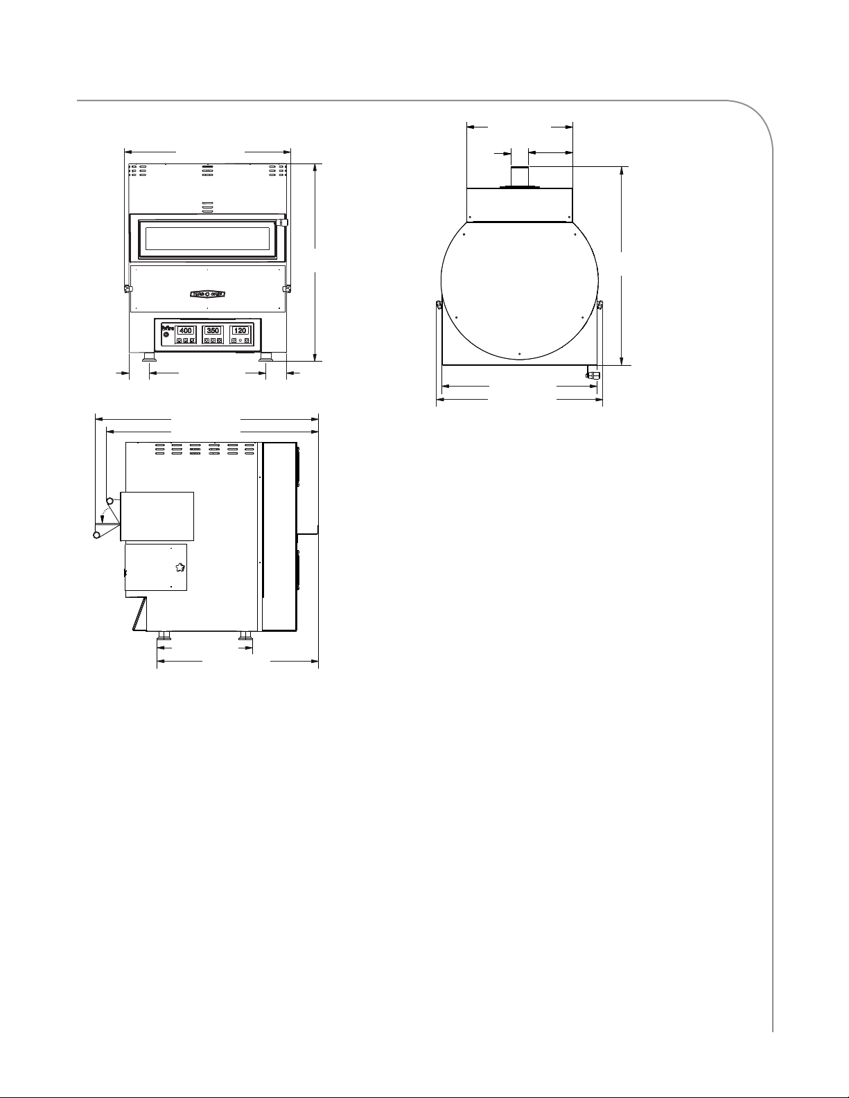
Figure 1: Fire Oven Dimensions
Performance
The TurboChef Fire provides the artisan hearthstyle pizza experience anywhere. Cooking at
842°F/450°C, the Fire can cook 14-inch fresh
dough pizzas in as little as 90 seconds. The oven
is small and ventless, so it can be placed virtually
anywhere without type I or type II ventilation.
This manual includes instructions for installing,
cleaning, and operating the Fire oven. If you have
questions that are not addressed in this manual,
contact Customer Support at 800.90TURBO
(+1 214.379.6000) or your Authorized Distributor.
Dimensions
Oven Dimensions
Height: 22.7” (576.6 mm)
Width: 19.01” (482.9 mm)
Depth (footprint): 18.55” (471.2 mm)
Depth (door closed): 24.39” (619.5 mm)
Depth (door open): 26.47” (672.3 mm)
Weight: 75 lb. (34 kg)
Cook Cavity Dimensions
Width: 14.75” (374.7 mm)
Depth: 14.75” (374.7 mm)
Clearances
Top: 2” (51 mm)
Sides: 2” (51 mm)
SPECIFICATIONS AND INSTALLATION
Page 12
2 SPECIFICATIONS AND INSTALLATION
Certifications
cULus, UL EPH
Oven Construction
Exterior
- Powder coated, corrosion-resistant steel outer
wrap and door
- 430 stainless steel construction
Interior
- 430 stainless steel interior
- Double wall insulated cooling keeps external
temperatures cool
Electrical Specifications
TurboChef recommends a Type D circuit breaker
for all installations outside the United States.
Single Phase
3. Check the cook cavity thoroughly for
accessories and literature.
4. Discard any packaging in the cook cavity.
Installation Warnings - Read Before Lifting Oven
WARNING: The Fire oven weighs
approximately 75 lb. (34 kg). Never lift with
fewer than two people.
WARNING: The oven must be properly
placed on a food station at all times.
TurboChef will not recognize a fallen oven as
a warrantable claim and is not liable for any
injuries that may result.
WARNING: This oven is not intended for
built-in installation (i.e., installing the oven in
any structure that surrounds the oven by five
or more sides). Be sure to provide a minimum
of 2” (51 mm) clearance for all sides and 2”
(51 mm) clearance for the top.
WARNING: This oven is not intended to be
stacked.
North America: 208/240 VAC, 50/60 Hz,
3700/4800 W, 18/20 A, 30 A Plug
Europe/Asia/South America: 230 VAC, 50/60 Hz,
4500 W, 19.6 A, 32 A Plug
Australia: 230 VAC, 50/60 Hz, 4500 W, 19.6 A,
32 A Plug
Installation
Install or locate this appliance only in accordance
with the instructions below.
Unpacking Instructions
1. Remove the oven from its packaging.
2. Before discarding, check the packaging
thoroughly for accessories and literature.
NOTE: Packaging may also be retained in case the
oven may at some point be shipped somewhere
else or returned to the manufacturer.
Lifting and Placing the Oven
1. Prepare a surface at least 18.55” (471.2 mm)
deep and capable of supporting 80 lb (36.3 kg).
NOTE: Do not remove the oven legs.
2. Position one or more persons at the left and
right sides of the oven.
3. Place hands under the oven and lift.
4. Place the oven on the prepared surface,
ensuring no edges are hanging off the sides.
5. Ensure the lower access panel is properly
installed (thumbscrews are tight), refer to
Figure 6, Page 5 for illustration.
6. Plug in the oven.
Page 13

3
Installation Near Open Heat Source
When placing a TurboChef oven near an open
heat source (Figure 2), strictly adhere to the
following:
- If the oven is being placed near a grill or stove,
a divider must exist between the oven and the
open heat source, with a minimum of 6” (152
mm) between the oven and the divider.
- If the oven is being placed near a fryer, a
divider must exist between the oven and fryer,
with a minimum of 12” (305 mm) between
the oven and the divider.
- The height of the divider must be greater than
or equal to the height of the oven (22.7” or
576.6 mm).
- Verify the oven location has a minimum 2”
(51 mm) clearance on top and a minimum 2”
(51 mm) clearance on each side.
Voltage Selection
For North America oven models, the oven will
detect 208 or 240 incoming voltage.
Ventilation
The TurboChef Fire oven has been approved by
Underwriter’s Laboratory LLC for ventless
operation (UL® KNLZ listing) for all food items
except for foods classified as “fatty raw proteins.”
Such foods include bone-in, skin-on chicken, raw
hamburger meat, raw bacon, raw sausage, steaks,
etc. If cooking these types of foods, consult local
HVAC codes and authorities to ensure compliance
with ventilation requirements.
To ensure continued compliance with all health,
building, and fire codes, you are required to maintain clean and sanitary conditions around your
oven at all times.
NOTE: In no event shall the manufacturer assume
any liability for damages or injuries resulting from
installations which are not in compliance with the
instructions and codes previously listed. Failure to
comply with these instructions could result in the
issuance of a temporary cease and desist order from
the local health department until the environment
concerns are addressed.
Partition
22.7” (576.6 mm)
Above Counter Top
Grill
Figure 2: Installation Near Open Heat Source
6”
(152 mm)
Minimum
12”
(305 mm)
Minimum
Counter Top / Table
Partition
22.7” (576.6 mm)
Above Counter Top
Deep Fryer
SPECIFICATIONS AND INSTALLATION
Page 14

4 SPECIFICATIONS AND INSTALLATION
Installing the Oven Handle
1. While the oven is off and cool, open the oven
door (Figure 3).
2. Using a flat-head screwdriver, remove the two
screws on the outside of the oven door
(Figure 3).
3. Install the handle bracket as shown in Figure
4, using the screws removed in step 2.
4. Close the oven door.
5. Attach the handle to the bracket using the
provided screw and washer (Figure 5).
CAUTION: DO NOT over-tighten the
handle. The handle may break if over-tightened.
Oven Door Screws
Figure 3: Oven Door Screw Location
Handle
Screw
Washer
Bracket
Figure 4: Bracket Installed to Oven Door
Handle
Figure 5: Handle Installed
Page 15

Daily Maintenance
Page 16

Page 17

5
Daily Maintenance
Follow the steps below when cleaning your Fire oven.
Use only TurboChef ®-approved cleaning chemicals.
The use of any other cleaning products may damage
Supplies and Equipment
TurboChef ® Oven Cleaner (Product Number:
103180), nylon scrub pad, cleaning towel, disposable
gloves, protective eyewear, dust mask (optional)
critical oven components, resulting in a non-warranty
service call.
Oven Door
Thumbscrew
Figure 6: Maintenance
Thumbscrew
Lower Access Panel
Oven Interior
Step 1: Prepare the Oven
CAUTION: The oven operates at 842°F (450°C) and may cause injury if not allowed to cool properly.
• Turn off the oven by pressing the On/Off key.
• Cooling takes approximately two hours (or longer). DO NOT clean the oven until the oven is cool.
Step 2: Wipe the Oven Interior
• Remove the lower access panel by removing the two thumbscrews (see Figure 6, above).
• Use a food vacuum or damp towel to remove large particles from the oven interior.
Step 3: Clean the Oven Interior
• Spray TurboChef ® Oven Cleaner onto a clean towel or nylon scrub pad and scrub the interior of the oven and
the inside portion of the lower access panel.
CAUTION: DO NOT spray Oven Cleaner into any holes or openings in the oven interior. Doing
so can damage critical oven components, resulting in a non-warranty service call.
• Open the oven door and gently wipe down the inside of the Door.
• If necessary, spray a small amount of Oven Cleaner on stains and allow to penetrate for five minutes, then clean
with a nylon scrub pad.
Step 4: Rinse or Wipe the Oven Interior
CAUTION: DO NOT use a hose or water jet for cleaning. Doing so can damage critical oven components,
resulting in a non-warranty service call.
• Wipe down the oven interior with a clean damp towel.
• Dry the oven interior with a clean towel.
Step 5: Clean the Oven Exterior
• Reinstall the lower access panel and secure it with the two thumbscrews.
• Wipe the oven exterior with a clean, damp towel.
CAUTION: DO NOT spray chemicals into any openings, such as the vents on the side and front or
the perforation on the back. Doing so can damage critical oven components, resulting in a non-warranty
service call.
• The oven is ready to turn on.
DAILY MAINTENANCE
Page 18

6
DAILY MAINTENANCE
This page intentionally
left blank.
Page 19

Oven Operation
Page 20

Page 21

7
UPPER TEMPERATURE
65 7
1
TIME
PRESETS
Figure 7: Oven Controls
Oven Controls
1. On/Off Key
Press to turn the oven on or off.
2. Time Preset Keys
Press presets 1 through 6 to activate a timer.
3. Up and Down Keys
Press the Up and Down keys to change the oven
temperature (page 8), the time presets (page 8), or
the parameters (pages 8-9).
LOWER TEMPERATURE TIME
3 42
5. Upper Temperature Display
Displays the current Upper Temperature. A green
light in the lower-left corner of this display will
blink during warmup and turn solid once it has
reached the set temperature.
6. Lower Temperature Display
Displays the current Lower Temperature. A green
light in the lower-left corner of this display will
blink during warmup and turn solid once it has
reached the set temperature.
7. Time Display
4. Temperature Key
Press the Temperature Key to toggle between
setting the upper and lower temperatures (page 8).
Shows the amount of time left for the selected
preset. The time is displayed in seconds, up to
1,999 (33 minutes and 19 seconds).
Cooking
1. Press the On/Off key to turn the oven on.
2. Allow the oven to warm up. The green light in the bottom-left corner of the Upper Temperature
Display and the Lower Temperature Display will blink during warmup. Once the oven has finished
warming up, the lights will stop blinking and stay solid.
3. Open the oven door and using the provided paddle and cooking screen, slide the product into
the oven and close the oven door.
4. Press the desired timer (1 through 6).
NOTE: Once the timer reaches 0, the oven will begin beeping. To stop the beeping, press any of the
Time Preset keys.
5. Open the oven door and remove the product from the oven and close the oven door.
CAUTION: Dish and inside of oven/oven door are hot!
6. When finished cooking for the day, press the On/Off key to turn the oven off and begin cooling down.
OVEN OPERATION
Page 22

8 OVEN OPERATION
Setting the Temperatures
Two different temperatures can be set: one for the upper heating zone and one for the lower heating zone.
These temperatures range from off to 842°F (450°C).
NOTE: When a temperature is set to off, the display will read 32°F (0°C).
To set the temperature:
1. While the oven is on, press the Temperature key to access the upper temperature (the upper
temperature will begin flashing).
2. Use the Up and Down keys to set the upper temperature.
3. Press the Temperature key again to save the upper temperature and to access the lower temperature.
4. Use the Up and Down keys to set the lower temperature.
5. Press the Temperature key again to save the lower temperature.
NOTE: If changing only one temperature, simply press the Temperature key to bypass the upper or lower
temperature without changing it.
Setting the Timers
Six different timers can be set to accommodate different items.
To set a timer:
1. Make sure no timers are running.
2. While the oven is on, press and hold the desired timer button (1 through 6) for two seconds. The value
indicated on the Time display will begin flashing.
3. Use the Up and Down keys to set the time.
4. Press and hold the same timer button for two seconds to save the time.
NOTE: If you wait five seconds without pressing any buttons, the timer will save automatically.
To pause a timer:
- Press any of the Time Preset keys. The time on the Time Display will flash to indicate the timer
is paused.
- To resume the timer, press any of the Time Preset keys again.
- To reset the timer to 0, press and hold any of the Time Preset keys for two seconds. The oven will
begin beeping to indicate the timer has reached zero. To stop the beeping, press any of the Time
Preset keys.
Setting the Parameters
Access the parameter settings to change oven options. For a full list of parameters, descriptions, and
values, see page 9.
To set the parameters:
1. While the oven is off, simultaneously press and hold the Time Preset 2 and 3 keys for two seconds. The
Upper Temperature display will read “PA”.
2. Press the Down key until the Time display reads “-19” (negative nineteen).
3. Simultaneously press and hold the Time Preset 2 and 3 keys for two seconds. The Upper Temperature
display will now read “P0”.
4. Refer to the table on page 9 and use the Time Preset 2 and 3 keys (increase and decrease parameter
numbers) to navigate through the parameters.
5. Use the Up and Down keys to change the values.
6. When finished, press the On/Off key.
Page 23

9
Parameter Description
Temperatures shown in °C or °F.
P0
P1 Factory Use Only n/a n/a n/a 0
P2 Factory Use Only °F/°C n/a n/a 4°F/2°C
P3 Factory Use Only °F/°C n/a n/a 0°F/0°C
P4 Factory Use Only °F/°C n/a n/a 212°F/100°C
P5 Minimum Setting of Heater 1 °F/°C 32/0 P6 122°F/50°C
P6 Maximum Setting of Heater 1 °F/°C P5 842/450 842°F/450°C
P7 Factory Use Only °F/°C n/a n/a 0°F/0°C
P8 Factory Use Only °F/°C n/a n/a 212°F/100°C
P9 Minimum Setting of Heater 2 °F/°C 32/0 P10 122°F/50°C
P10 Maximum Setting of Heater 2 °F/°C P9 842/450 842°F/450°C
P11 Factory Use Only Minutes n/a n/a 30
P12 Factory Use Only Minutes n/a n/a 30
P13 Factory Use Only Minutes n/a n/a 30
0 = °C
1 = °F
Unit of
Measure
n/a 0 1 1
Minimum
Value
Maximum
Value
Default Value
P14 Preset Timer 1 Seconds P20 P21 80
P15 Preset Timer 2 Seconds P20 P21 90
P16 Preset Timer 3 Seconds P20 P21 100
P17 Preset Timer 4 Seconds P20 P21 110
P18 Preset Timer 5 Seconds P20 P21 120
P19 Preset Timer 6 Seconds P20 P21 130
P20 Minimum Settable Time Seconds 0 P21 0
P21 Maximum Settable Time Seconds P20 1,999 240
P22 Duration of Buzzer Sound Seconds 0 60 15
P23 Factory Use Only n/a n/a n/a 0
P24 Factory Use Only °F/°C n/a n/a 140°F/60°C
P25 Factory Use Only n/a n/a n/a 0
P26 Factory Use Only Seconds n/a n/a 20
P27 Factory Use Only % n/a n/a 67
P28 Factory Use Only % n/a n/a 67
P29
Time between selection and timer
start
Seconds 2 20 2
OVEN OPERATION
Page 24

10
OVEN OPERATION
This page intentionally
left blank.
Page 25

Troubleshooting
Page 26

Page 27

Troubleshooting: Fault Code Er1
Er1 is displayed on the upper temperature display and indicates a damaged upper
RTD. The oven will beep when this error occurs.
11
Is the wiring from the
upper RTD to the control
board OK? (See page 15
for schematic.)
YES
Is the top heater
element defective?
Resistance of
approximately 30 Ω
at room temperature.
NO
Correct
the wiring.
YES
Is the upper RTD
YES
NO
Replace the defective
heater element.
operating properly?
Resistance of
approximately 4 Ω at
room temperature.
Is the control board
operating properly?
NO
Replace the control
board.
Troubleshooting: Fault Code Er2
YES
NO
Ensure wiring is correct.
If necessary, replace the
upper RTD.
Replace the RTD.
Er2 is displayed on the lower temperature display and indicates a damaged lower RTD.
The oven will beep when this error occurs.
Is the wiring from the
lower RTD to the control
board OK? (See page 15
for schematic.)
YES
Is the bottom heater
element defective?
Resistance of
approximately 24 Ω
at room temperature.
YES
Is the lower RTD
YES
NO
NO
Replace the defective
heater element.
operating properly?
Resistance of
approximately 2 Ω at
room temperature.
Is the control board
operating properly?
NO
Replace the control
board.
NO
Correct the wiring.
YES
Replace the RTD.
Ensure wiring is correct.
If necessary, replace the
lower RTD.
TROUBLESHOOTING
Page 28

12 TROUBLESHOOTING
Ht is displayed on the upper temperature display and indicates that the temperature in
the controls compartment is too hot. The oven will beep when this error occurs.
Troubleshooting: Fault Code Ht
Is the wiring from the
controls compartment
cooling fan to the control
board OK? (See page 15
for schematic.)
YES
Replace the control
board.
Use the following troubleshooting steps when the oven is not heating properly.
Is the high-limit
thermostat tripped?
YES
NO
Correct
the wiring.
NO
Is the controls
YES
compartment cooling fan
operating properly?
Correct
the wiring.
NO
NO
Troubleshooting: Oven Not Heating
Is the oven receiving
YES
correct voltage from the
outlet?
NO
Is the wiring from the
controls compartment
cooling fan to the
contactor relay OK?
(See page 15 for
schematic.)
YES
Replace the controls
compartment
cooling fan.
Verify that the breakers
are not tripped, the outlet
is not damaged, and that
the electrical supply is
sucient for the oven.
Reset and
determine
why it tripped
- excess grease
buildup, etc.
Is either
fuse open/
blown?
YES
Replace and
determine
why it/they
opened/blew.
Replace the
control board.
Correct wiring.
NO
Are either heaters defective?
YES
Replace the
defective
heater(s).
Replace the
contactor relay
YES
NO
NO
Is the contactor
relay defective or
damaged?
YES
NO
Is the wiring from
the contactor relay
to the control board
OK? (See page 15
for schematic.)
Page 29

Use the following troubleshooting steps when the oven is not cooking properly.
YES
Are there any fault codes
present? See pages 10-11.
NO
Is the oven
heating
properly?
YES
Are the temperature
and timer settings set
properly?
NO
NO
Troubleshooting: Food Not Cooking Properly
Does the problem occur with all items?
For example, everything is undercooked/
overcooked/etc.?
Troubleshoot the
YES
Follow the “Troubleshooting: Oven
Not Heating” steps on page 11.
fault(s) using the
steps on pages 10-11.
YES
Ensure that the correct
amount is being cooked
- not more or less than
the recipe species.
Ensure the food item is
being properly stored/
prepared before cooking.
NO
13
NO
Is the food item in the
correct starting state
(e.g., frozen, fresh, etc.)?
NO
YES
Is the correct amount of
food being cooked?
YES
Correct the settings.
YES
Replace the
control board
NO
NO
Are the temperature
and timer settings set
properly?
YES
Dos the problem occur
EVERY time the food
item is cooked?
Is the food item being prepared correctly and
consistently? For example, ingredients are correct
thickness, pizza dough is correct consistency, etc.
YES
Are there any fault codes
present? See pages 10-11.
NO
Is the oven
heating
properly?
YES
NO
Ensure that the food item
is properly prepared.
Troubleshoot the
YES
NO
Follow the “Troubleshooting: Oven
Not Heating” steps on page 11.
fault(s) using the
steps on pages 10-11.
TROUBLESHOOTING
Page 30

14 TROUBLESHOOTING
This page intentionally
left blank.
Page 31

Oven Schematic
Page 32

Page 33

RED (L1)
NEMA 6-30
RED (L1)
RED (L1)
RED (L1)
RED (L1)
BLU (-)
RED (+)
RED (+)
33
32
31
30
29
28
27
26
25
24
23
22
21
18
17
16
15
14
13
12
11
10
15
BLU (L2)
S2
BOTTOM RTD
RED (+24)
BLK (-24)
RED (L1)
RED (L1)
RED (L1)
RED (L1)
WHT (L1)
S1
TOP RTD
VOLTAGE SELECTOR
OVEN LIGHT
INTERIOR
R1 TOP ELEMENT
1600 W
R2 BOTTOM ELEMENT
2100 W
RED (L1)
BLU (L2)
RED (L1)
BLK (L2)
RED (L1)
BLK (L2)
13
RED (L1)
BLK (L2)
BLU (L2)
A1
A2
RED (L1)
6146
4
2
BLU (L2)
BLU (L2)
RED (L1)
5
3
1
H1
CONTACTOR
9
8
7
6
5
4
3
2
1
WHT (L1)
WHT (L1)
GREEN (L1)
RED (L1)
COOLING FAN
M5
M3
TOP MOTOR
TOP BACK
COOLING FAN
REAR BOTTOM
OVER LIMIT
TS1
C)
NC (450
BLU (L2)
GREEN (L1)
BLK (L2)
C1
M1
Figure 8: Oven Schematic - Single Phase
RED (L1)
GREY (L1)
BOTTOM MOTOR
M2
COOLING FAN
KEYBOARD
M4
GREY (L2)
BLACK (L1)
WHITE (L2)
GREEN (GND)
F1-20 AMP
F2-20 AMP
F1
F2
L1 PE
L2
OVEN SCHEMATIC
Page 34

16 OVEN SCHEMATIC
This page intentionally
left blank.
Page 35

Appendix
Replacing Oven Components
Page 36

Page 37

Replacing Oven Components
This appendix provides illustrations for removing serviceable items, as well as the item numbers and
descriptions for those items. It also includes the item numbers and descriptions for the fasteners
used to secure each component to the oven chassis.
If you have any questions that are not addressed in this manual or appendix, please contact
TurboChef Customer Service at 800.90TURBO or +1 214.379.6000.
A-1
APPENDIX REPLACING OVEN COMPONENTS
Page 38

A-2 APPENDIX REPLACING OVEN COMPONENTS
Replacing Items
DANGER: Before replacing any oven component, ensure the oven is removed from any power
source. Replacing a component while the oven is plugged in can result in serious injury or death
CAUTION: Be careful to not tear the insulation when servicing components. Always reinstall the
insulation properly before reinstalling the outer shell.
NOTE: Fasteners listed are required for installing component to oven.
30
16
21
20
17
18
8
29
1
51212
2
24
5
2333
32
6
24
1
15
19
13
28
14
(x2)
27
26
10
4
31
11
7
9
22
(x4)
3
Figure
Reference #
1 Blower Motor* FRE-3001 (x2) Screw, PPH, SS, M5x25mm LGx .8mm 101344 (qty 2)
2 Catalytic Converter FRE-1019
3 Control Board FRE-3006 Screw, PFH, SS, M4x35mm LGx .8mm 101439 (qty 6)
4 Cooling Fan, Controls FRE-1046
5 Cooling Fan, Rear 100516 (x2)
Item Description Item Part Number Fastener Description
Screw, SH MTL, #8 x 1/2 Serrated PHTRH
Bracket, Catalyst Holder
Screw, PPH, SS, M4x30mm LGx .8mm
Nut, Hex, SS, M4
Screw, #10-32x1/2, Hex WSHR HD, Type 23
(Shared with Finger Guard)
*Ensure that the blower motor is properly aligned.
Fastener Part
Number(s)
101688 (qty 4)
FRE-1013 (qty 2)
101699 (qty 2)
101004 (qty 2)
101408 (qty 4)
Page 39

A3
Figure
Reference #
6 Cover, Back FRE-1016 Screw, M4x10mm LG, PPHD, S.S. 101671 (qty 8)
7 Cover, Bottom FRE-1133 Screw, M4x10mm LG, PPHD, S.S. 101671 (qty 7)
8 Cover, Top
9 Display Housing FRE-1112 Screw, M4x10mm LG, PPHD, S.S. 101671 (qty 2)
10 Display Housing, Cover FRE-1087 Screw, M4x10mm LG, PPHD, S.S. 101671 (qty 4)
11 Distribution Block FRE-1048 Screw, M5x12, Hex PPHD, CRES 101676 (qty 2)
12 Finger Guard 100087 (x2)
13 Fuse Holder 103548 Screw, M4x10mm LG, PPHD, S.S. 101671 (qty 2)
14 Fuse, F1 and F2, 20-amp 100599 None None
15
16
17
18
19 High Limit Thermostat FRE-1050 Screw, M4x10mm LG, PPHD, S.S. 101671 (qty 2)
Item Description Item Part Number Fastener Description
FRE-1059-1 (Red)
FRE-1059-2 (Green)
Handle, Kit
(kit includes bracket and hardware)
Hatch, Front
(kit includes thumb screws)
Heater, Bottom (approximately
24 at room temperature)
Heater, Top (approximately 30 at
room temperature)
FRE-1059-3 (Yellow)
FRE-1059-4 (White)
FRE-1059-5 (Black)
FRE-1059-6 (Blue)
FRE-3007 Included Included
FRE-3008-1 (Red)
FRE-3008-2 (Green)
FRE-3008-3 (Yellow)
FRE-3008-4 (White)
FRE-3008-5 (Black)
FRE-3008-6 (Blue)
FRE-3003 Included Included
FRE-3002 Included Included
Screw, M4x10mm LG, PPHD, S.S. 101671 (qty 5)
Screw, #10-32x1/2, Hex WSHR HD, Type 23
(Shared with Cooling Fan, Rear)
Included Included
Fastener Part
Number(s)
101408 (qty 4)
20 Keypad Back Panel FRE-1113 Screw, M4x10mm LG, PPHD, S.S. 101671 (qty 2)
21 Keypad Overlay FRE-1150 None None
22 Leg FRE-1055 None None
23 Light Bulb with Lens and Socket FRE-3005 None None
24 Magnet FRE-1162 (x2) Screw, FL HD Slot, SS, 90o M4x16mm LG, .7 Pitch 101428
25
26
27 Relay, Contactor FRE-1060 Screw, M4x8mm LG, PPHD, S.S. 101670
28
29
30 Screw, Thumb FRE-1163 None None
31 Voltage Module 100783
32 Window, Assembled FRE-3010 Included Included
33 Window, Glass FRE-3004 Included Included
34
Paint, Touch-Up Kit
(not shown)
Power Cord, Domestic
Power Cord, International
Power Cord, Australia
RTD, Lower (approximately 2 at
room temperature)
RTD, Upper (approximately 4 at
room temperature)
Wire Harness
(not shown)
FRE-3009 None None
100187
100195
i1-9136
FRE-1053 Screw, M4x10mm LG, PPHD, S.S. 101671
FRE-1052 Screw, M4x10mm LG, PPHD, S.S. 101671
FRE-1160 None None
None None
Screw, PPH, SS, M4x30mm LGx .8mm
Nut, Hex, SS, M4
101699
101004
APPENDIX REPLACING OVEN COMPONENTS
Page 40

For service or information:
Customer Support at 800.90TURBO
+1 214.379.6000 or Your Authorized Distributor
Part Number: FRE-1002 / Revision B / October 2014
Country Code: NA/EU
Global Operations
2801 Trade Center Drive
Carrollton, Texas 75007
TM
+1 214.379.6000
+1 214.379.6073
TurboChef International
Business & Technology
Centre
Bessemer Drive
Stevenage
Herts SG1 2DX
United Kingdom
+44 8456021544
+44 8456021636
Customer Support
800.90TURBO
+1 214.379.6000
turbochef.com
 Loading...