

Page 1
F53O
OWNER'S MANUAL
BETRIEBSANLEITUNG
MODE D'EMPLOI
MANUALE D'USO
MANUAL DEL USUARIO
HANDLEIDING
BRUKSANVISNING
KÄYTTÖOHJE
www.tunturi.com
• SER IAL NU MBE R • SE RIE NNU MME R
• NUM ERO DE SE RIE • NÚM ERO DE SE RIE
• NUM ERO DI SE RIE • SER IEN UMM ER
• SER IEN NUM MER • SAR JAN UME RO
Page 2
1
5
2
3
6
7
4
2
8
Page 3

O WN E R 'S M A NU A L • F 53 0
G B
O W N E R ' S M A N U A L F 5 3 0
I N F O R M A T I O N A N D
WA R N I N G S
Please read this owner’s manual through carefully
before assembling, using and servicing the workout
cycle! Follow the instructions described in this
manual carefully.
The equipment has been designed for home
and light commercial use. The Tunturi warranty
applies only to faults and malfunctions in home
(warranty period: 24 months). Please note that the
warranty does not cover damage due to shipping
or negligence of adjustment or maintenance
instructions described in this manual.
NOTE ABOUT YOUR HEALTH
Before you start any training, consult a
•
physician to check your state of health.
If you experience nausea, dizziness or other
•
abnormal symptoms while exercising, stop your
workout at once and consult a physician.
To avoid muscular pain and strain, begin each
•
workout by warming up and end it by cooling
down (slow pedalling at low resistance). Don’t
forget to stretch at the end of the workout.
NOTE ABOUT THE EXERCISING
ENVIRONMENT
Place the device on a rm, level surface. Place
•
the device on a protective base.
Make sure that the exercising environment has
•
adequate ventilation. To avoid catching cold, do
not exercise in a drafty place.
In training, the equipment tolerates an
•
environment measuring +10°C to +35°C. The
equipment can be stored in temperatures ranging
between -15°C and +40°C. Air humidity in the
training or storage environment must never exceed
90 %.
NOTE ABOUT USING THE EQUIPMENT
Parents or others responsible for children
•
should note that children’s natural playfulness and
curiosity may lead to situations and behaviour
for which the device is not designed. If children
are allowed to use the device, they should be
supervised and taught to use the device properly,
keeping in mind the child’s physical and mental
development and their personality. The exercise
device is not a toy.
Before you start using the device, make sure
•
that it functions correctly in every way. Do not use
a faulty device.
Only one person may use the device at a time.
•
Wear appropriate clothing and shoes when
•
exercising.
Do not use the device when the protective
•
covers are not in place.
Press the keys with the tip of the nger; your
•
nails may damage the key membrane.
Never lean on the meter.
•
Do not let the meter come into contact with
•
water. Always dry the surface of the meter, if there
are any drops of sweat on it. Use a soft, absorbent
cloth. Do not use solvents to clean the meter
surface.
Protect the meter from excess sunlight: it
•
may fade the colors of the meter box and surface
membrane.
Do not attempt any servicing or adjustment
•
other than those described in this manual.
The given service instructions must be followed
carefully.
The device is not recommended for persons
•
weighing over 110 kg.
A S S E M B LY
Open the transport package on its side. Take the
parts out of the package and make sure the package
includes all the following parts:
1. Front frame assembly
2. Seat frame assembly
3. Main beam tube
4. Seat (2 pcs)
5. Handlebar assembly
6. Electronic meter and bracket
7. Transport wheel (2 pcs)
8. Wheel / Foot coupler (4 pcs)
9. Foot (2 pcs)
10. Pedals and straps (2 pcs)
11. Front sleeve
12. Hardware kit (marked with an asterisk *
in the spare part list)
If you notice that a part is missing, contact the
dealer and give the model, serial number and spare
part number (the spare part list is in the back of the
manual). The package includes also a silicate bag
for absorbing moisture during transportation and
storage. Assemble the recumbent cycle as follows
(left, right, front and back are as seen from the
exercising position):
3
Page 4

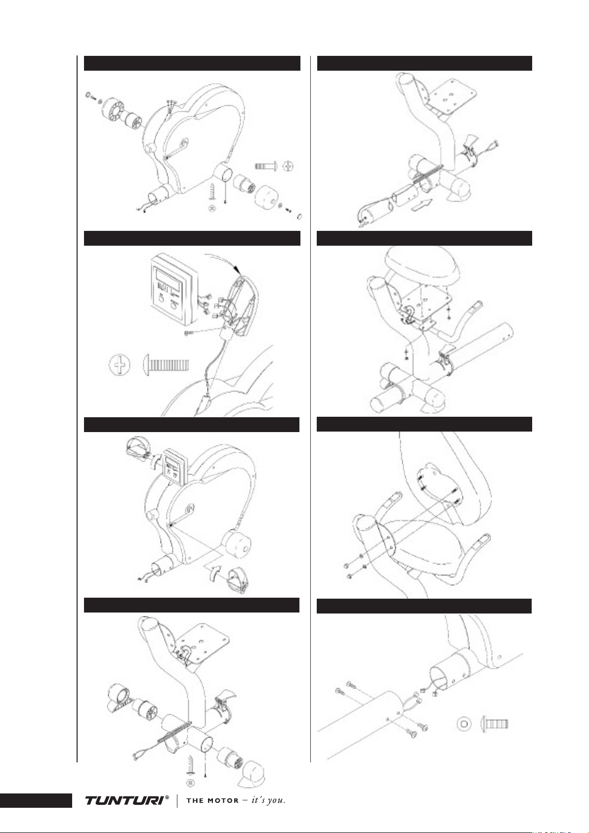
A S S E M B LY
TRANSPORT WHEELS FIG. 1
Insert wheel couplers into front frame assembly,
secure each with an 4x15 screw. Push wheels onto
couplers and secure each with an M6x25 screw and
washer. Cover each bolt by pushing a green end cap
into hole at the center of each wheel.
coming out of the handle bar and main beam tube.
Place the seat cushion on the seat plate, line up
the six bolts extending from the bottom of the seat
with the six holes on the seat plate. Using two
M8 nylock nuts, attach the seat to the seat plate
at the two front bolts. Align the four holes of the
handlebar with the four bolts of the seat cushion.
Secure the handlebar and the bottom seat cushion
using four M8 nylock nuts.
METER FIG. 2
Put two 1.5 V AA batteries into the battery holder
at the back of the meter, noting the + and - marks
on the bottom of the holder. Remove the wire
tying the meter wire on the bracket support tube.
Route the meter wire through the meter bracket.
Press the meter bracket into the bracket support
tube and line up the screw holes between the meter
bracket and the bracket support tube. Secure with
an M4x15L self-taping screw. Connect the meter
wire to the plug on the back side of the meter.
Tuck the wire inside the meter and carefully slide
the meter onto the meter bracket. NOTE! Be
careful not to damage the meter wire! Remove the
protecting lm from the display.
PEDALS FIG.3
The pedals are distinguished by the markings R
and L on their shafts (R = right, L = left). Fasten
the right pedal to the right pedal crank turning
clockwise and the left pedal to the left pedal crank
turning counterclockwise. Fasten the pedal straps.
Choose the strap tightness, set the appropriate
strap hole on the retainer from below and pull
forcibly upward. The pedal straps are adjustable.
Especially when the device is new, the fastening of
the strap may seem relatively tight.
SEAT BACK FIG.7
Install the seat back cushion onto the rear seat
bracket using four acorn nuts (closed end nut).
MAIN BEAM TUBE AND
FRONT ASSEMBLY FIG. 8
Connect the wires from the main beam tube and
the front frame assembly. Attach the main beam
tube to the front frame assembly using four M8x20
bolts, two bolts on both sides. NOTE! Be careful
not to damage the wires!
U S E
CORRECT BODY POSITION
The Recumbent Cycle F 530 is designed to
comfortably distribute your weight evenly over
your buttocks and lumbar region of your lower
back. Your legs are also positioned closer to the
level of your heart, allowing a less strenuous and
more efcient cardiovascular workout. To ensure
proper positioning please follow the recommended
guidelines:
ADJUSTING THE SEAT TO
FEET FIG.4
Insert a foot coupler into each side of rear frame
cross tube. Secure each with a 4x15 screw. Push feet
onto couplers.
PEDAL DISTANCE
The lenght of the seat rail should be adjusted
so that your knee remains slightly bent (not
completely straight) when your leg is extended to
the furthest pedaling point forward. To adjust the
distance between the seat and the pedals: lift the
MAIN BEAM TUBE FIG. 5
Insure that the seat adjustment lever is in the
release (upward) position. Loosen the plastic
bushing at the back end of the main beam tube and
pull the pulse cable through the main beam tube
using the pulling string. Slide the main beam tube
through the seat frame assembly tube.
lever located below the seat to release the lock. To
extend the distance, push forward with your feet
in the pedals. Backpedal to nd the comfortable
distance. To reduce the distance, pull the front
frame assembly using the scalloped handle next
to the left side crank. Push the lever back to
horizontal position to lock the attachment.
Place the plastic bushing around the pulse
cable and push the bushing back to its place in the
hole at the back of the main beam tube.
HANDLEBAR AND SEAT CUSHION FIG.6
Position the handlebar so that it rests on the
supports of the seat plate. Connect the cables
O WN E R 'S M A NU A L • F 53 0
4
Page 5

O WN E R 'S M A NU A L • F 53 0
G B
ADJUSTING PEDALLING RESISTANCE
Adjust resistance by turning the knob below the
meter. To increase resistance, turn clockwise (+),
to decrease resistance turn counterclockwise (-).
E X E R C I S I N G
Working out using a recumbent cycle is excellent
aerobic exercise, the principle being that the
exercise should be suitably light, but of long
duration. Aerobic exercise is based on improving
the body’s maximum oxygen uptake, which in turn
improves endurance and tness. The ability of the
body to burn fat as a fuel is directly dependent
on its oxygen-uptake capacity. Exercise of long
duration within a pulse range that is about 50-60
% of the maximum pulse burns effectively fat, i.e
helps you lose weight. Exercise in a range that is
about 70-80 % of the maximum develops the heart
and respiratory system, and overall endurance, i.e.
it improves your condition. If you don’t know your
own maximum pulse rate you can use the following
formulae as a guideline:
WOME N: 226 - AGE, M EN: 2 20 – AGE
However, it is advisable to make sure by consulting
your doctor. For example, to lose weight, a
50-year-old man should exercise at a resistance and
pedalling speed that raise his pulse to about 85-105
beats/min.
It is important to monitor your heart rate
throughout the exercise session. Many people begin
an exercise program too zealously and discontinue
because it becomes too difcult. Aerobic exercise
should above all be pleasant. You should perspire,
but you should not get out of breath during the
workout. You must, for example, be able to speak
and not just pant while pedalling. You should
exercise at least three times a week, 30 minutes at
a time, to reach a basic tness level. Maintaining
this level requires a few exercise sessions each week.
Once the basic condition has been reached, it is
easily improved, simply by increasing the number
of exercise sessions. Exercise is always rewarding for
weight loss, because it is the only way of increasing
the energy spent by the body. This is why it is
always worthwhile to combine regular exercise with
a healthy diet. A dieter should exercise daily at rst 30 minutes or less at a time, gradually
increasing the daily workout time to one hour.
You should start slowly at a low pedalling speed
and low resistance, because for an overweight
person strenuous exercise may subject the heart
and circulatory system to excessive strain. As tness
improves, resistance and pedalling speed can be
increased gradually.
M E T E R
The user friendly meter of the F 530 recumbent
cycles measures time, speed, pulse, estimated
energy consumption, and distance. The meter
switches on automatically when you rst press a
key or start pedalling, and switches off when you
have not pedalled or pressed any key for about 4
min.
NOTE! Protect the meter from direct sunlight,
as it may damage the liquid crystal display. Do
not expose the meter to water or severe impacts, as
these may also damage the meter.
METER DISPLAYS AND FUNCTIONS
TIME
Displays the elapsed time of the exercise session
(00:00-99:59).
SPEE D
Displays the current speed in MPH (GB/USAversion) or in km/h (0-99).
PULS E
Displays the pulse value during exercise (40-220
bpm). NOTE! Pulse is measured by sensors in
the handle bars. Pulse is measured when the user
of F530 is touching both sensors simultaneously.
Reliable pulse measurement requires that the skin
is constantly touching the sensors and that the skin
is slightly moist.
CALO RIES
Displays an estimate of kilocalories consumed
(0-999.9). This is an approximate calculation
determined by the number of crank rotations.
DISTANCE
Displays the distance traveled in miles (GB/USAversion) or in kilometers (0-999.9).
METER KEYS
RESE T
Press this key to set all data to zero.
MODE / SCAN
The automatic SC A N-function is always activated
in the TI ME display: each function is displayed
consecutively. Deactivate SCA N by pressing the
MODE / SC AN key.
M A I N T E N A N C E
The Recumbent Cycle F 530 requires very little
maintenance. We recommend, however, that you
make sure all the fastening screws are tight after
approximately one week of use. Turn the cycle on
its side and tighten the screws, if necessary. From
time to time check that the screws and nuts are
tight. Clean the cycle with a damp cloth. Do not
use solvents.
Please contact your dealer immediately if you
notice any defects or malfunctions while using your
equipment. Please state the nature of the problem,
5
Page 6

conditions of use, purchase date and serial number
of your equipment. In spite of continuous quality
control, individual defects and malfunctions may
occur due to individual components. It is in most
cases unnecessary to take the whole cycle for repair,
as it is usually sufcient to replace the defective
part.
CHANGING BATTERIES
If the meter display fades considerably or
completely, change the batteries. Pull the meter out
and remove the old batteries from the holder at the
back of the meter. Push the new batteries into the
holder (2 x 1.5 V AA) and push the meter back
into its place at the top of the handlebar support
tube.
T R A N S P O R T A N D S T O R A G E
Move the recumbent cycle according to the
following instruction: stand behind the cycle, grip
the seat back with one hand and the handlebar
with the other. Lift the cycle so that it rests on
the transport wheels and move it by wheeling.
Lower the cycle onto the oor while holding on
to the seat back and the handlebar and remaining
all the time behind the device. NOTE! Follow
the transportation instructions because lifting the
recumbent cycle incorrectly may strain your back
or cause other risk of accidents.
To prevent malfunctioning of the cycle, store
in a dry place with as little temperature variation as
possible, protected against dust.
D I M E N S I O N S
Length ............170 cm Height ..........104 cm
Width ..............64 cm Weight .............40 kg
All Tunturi models are designed to meet the
electro-magnetic compatibility directive, EMC and
are afxed with the CE conformity marking.
NOTE! The instructions must be followed
carefully in the assembly, use and maintenance
of your equipment. The warranty does not
cover damage due to negligence of the assembly,
adjustment and maintenance instructions described
herein. Changes or modications not expressly
approved by Tunturi Ltd will void the user’s
authority to operate the equipment!
Due to our continuous programme of product
development we reserve the right to change
specications without notice.
B E T R I E B S A N L E I T U N G F 5 3 0
W I C H T I G E
S I C H E R H E I T S H I N W E I S E
Diese Betriebsanleitung ist ein wesentlicher
Bestandteil Ihrer Trainingsausrüstung. Lesen Sie
dieses Handbuch daher aufmerksam durch, bevor
Sie Ihr Trainingsgerät montieren, mit ihm
trainieren oder es warten. Bitte bewahren Sie dieses
Handbuch auf. Es wird Sie jetzt und zukünftig
darüber informieren, wie Sie Ihr Gerät benutzen
und warten. Befolgen Sie diese Anweisungen
immer sorgfältig.
Ihr neuer Heimtrainer von Tunturi wurde für
das Heimtraining und die leichte kommerzielle
Nutzung entwickelt. Die Garantie dieses Gerätes
beträgt 24 Monate für das Heimtraining. Sowohl
Tunturi, als auch seine nationalen Vertretungen
übernehmen keine Haftung für Verletzungen
oder Geräteschäden, die sich bei Dauereinsatz
in gewerblichen Fitnesscentern, Sportvereinen
und vergleichbaren Einrichtungen ergeben. Für
Schäden, die durch Missachtung der
beschriebenen Einstellungs- und
Wartungsanweisungen entstehen, besteht kein
Garantie-Anspruch!
Suchen Sie vor dem Trainingsbeginn einen Arzt
•
auf, der Ihren Gesundheitszustand feststellt.
Bei Übelkeit, Schwindelgefühl oder anderen
•
anomalen Symptomen sollte das Training sofort
abgebrochen und unverzüglich ein Arzt aufgesucht
werden.
Das Trainingsgerät ist ein Sportgerät und kein
•
Spielzeug für Kinder. Aufgrund des natürlichen
Spieltriebes und der Experimentierfreudigkeit von
Kindern können Situationen und Verhaltensweisen
entstehen, für die das Trainingsgerät weder gebaut
noch abgesichert ist und die eine Verantwortung
seitens des Herstellers ausschließen. Wenn Sie
dennoch Kinder an das Trainingsgerät lassen,
müssen Sie deshalb deren geistige und körperliche
Entwicklung und vor allem deren Temperament
berücksichtigen, sie gegebenenfalls beaufsichtigen
und sie vor allem auf die richtige Benutzung des
Gerätes hinweisen.
Das Gerät sollte grundsätzlich nur von einer
•
Person benutzt werden.
Das Gerät auf möglichst ebenen Untergrund
•
stellen.
Dieses Gerät ist nicht für den Einsatz in
•
Feuchträumen (Sauna, Schwimmbad) vorgesehen.
B ET R I EB S A N LE I T UN G •F 53 0
6
Page 7

1 103 9012 Seat frame 1
2 153 9003 Seat back 1
3 153 9001 Seat bottom 1
4 M8 DIN 1587 Nut acorn 4
5 M8 DIN 985 Nut nylock 6
6 M8 DIN 125 Washer 10
7 203 9003 Handlebar (incl. 8,9,85) 2
8 213 9001 Handle grip, pair 1
9 533 7024 Plug 2
10 533 9006 Sleeve rear 1
11 533 9005 Sleeve front 1
12 103 9003 Main beam 1
13 533 9003 End plug 1
14 533 9014 End plug 1
15 533 9002 Connecting sleeve 4
*16 4,2X16 DIN 7981 Screw 4
17 533 9007 Foot 2
*18 M8x20 DIN 7985 Screw 4
19 213 9002 Handle, seat lock 1
20 343 9001 Axle bolt 1
21 M6 DIN 440 Washer 2
22 M6 DIN 917 Nut 2
23 523 9004 Clamping pad 2
24 523 9003 Clamping pad 2
25 103 9004 Front frame 1
26 503 9004 Meter bracket 1
27 233 9004 Meter EU 1
- 233 9005 Meter GB/US T-info 20/99 1
*28 M4x15 DIN 7985 Screw 1
29 403 9010 Sensor 1
29a 403 9002 Magnet 1
29b 403 9008 Heart rate cable 1
29c 403 9009 Cable for handle pulse 1
30 KA35x12 WN1441 Screw 2
31 503 9003 Sensor bracket 1
32 M5x10 DIN 7981 Screw 2
33 373 9004 Tension assembly 1
34 533 1014 Tension knob 1
35 M5x16 DIN 965 Screw 2
36 503 9006 Brake bow compl. 1
37 M5x10 DIN 7981 Screw 4
43 M5 DIN 125 Washer 4
49 643 9002 Spring 1
50 533 9001 Transport wheel 2
*51 M6 DIN 125 Washer 2
*52 M6x25 DIN 7985 Screw 2
53 533 7031 End cap 2
55 20 DIN 471 C clip 1
57 263 9002 P ulley, compl.(incl. 29a) 1
59 173 9003 Side cover, right (incl .94) 1
60 173 9004 Side cover, left (incl. 94) 1
61 M5x16 DIN 7985 Screw A4 7
62 M5 DIN 934 Nut 3
63 M8x20 DIN 7984 Screw 1
64 353 9003 Cranks, pair 1
65 653 9005 Screw 2
66 533 9010 Plug 2
67 363 1001 Pedals, pair (incl. 68) 1
68 363 1002 Pedal straps, pair 1
69 643 9001 Spring 1
70 513 9001 Tensioner plate, compl 1
71 72 0609 070 1 Fixing piece 1
72 M5 DIN 9021 Washer 2
73 M5x18 DIN 912 Screw 3
74 15 DIN 471 C clip 2
75 32 DIN 472 C clip 2
76 523 9005 Bearing housing (incl.75) 1
77 523 9007 Bearing housing 1
78 653 9004 Washer 1
79 653 9003 Washer teon 2
34
Page 8

80 263 9004 Pulley, drive belt 1
81 303 9002 Flywh. (incl.55,74,76-80) 1
82 M5x9 DIN 912 Screw 3
84 443 9002 Drive belt 1
85 403 9007 Handlebar pulse sensor 1
86 533 9015 Sleeve 1
94 423 9004 Decal set 1
- 553 9001 Hardware kit (incl. *) 1
- 583 9001 Owner’s manual 1
F530F530
35
Page 9

www.tunturi.com
TUNTURI OY LTD
P.O.BOX 750, FIN-20361
Turku, Finland
Tel. +358 (0)2 513 31
Fax +358 (0)2 513 3323
www.tunturi.com
583 9003
 Loading...