

Page 1
F2OO
OWNER'S MANUAL
BETRIEBSANLEITUNG
MODE D'EMPLOI
MANUALE D'USO
MANUAL DEL USUARIO
HANDLEIDING
BRUKSANVISNING
KÄYTTÖOHJE
www.tunturi.com
• SER IAL NU MBE R • SE RIE NNU MME R
• NUM ERO DE SE RIE • NÚM ERO DE SE RIE
• NUM ERO DI SE RIE • SER IEN UMM ER
• SER IEN NUM MER • SAR JAN UME RO
Page 2
G B
3
O WN E R 'S M A NU A L • F 2O O
O W N E R ' S M A N U A L F 2 O O
I N F O R M A T I O N
A N D WA R N I N G S
Please read this owner’s manual through
carefully before assembling, using and
servicing the workout cycle! Follow the
instructions described in this manual
carefully.
The equipment has been designed for home
use. Please notice that the warranty does
not cover any damages due to negligence
of assembly, adjustment or maintance
instructions described in this manual!
NOTE ABOUT YOUR HEALTH
Before you start any training, consult a
•
physician to check your state of health.
If you experience nausea, dizziness or other
•
abnormal symptoms while exercising, stop your
workout at once and consult a physician.
To avoid muscular pain and strain, begin each
•
workout by warming up and end it by cooling
down (slow pedalling at low resistance). Don’t
forget to stretch at the end of the workout.
nails may damage the key membrane.
Protect the meter from sunlight and always dry
•
the surface of the meter if there are any drops of
sweat on it.
Do not attempt any servicing or adjustment
•
other than those described in this manual.
The device must not be used by persons
•
weighing over 100 kg.
A S S E M B LY
Check that the following parts are in the package
(g. 1):
A Frame
B Rear support
C Handlebar support tube
D Meter
E Pedals (2)
F Handlebar
G Seat
H Seat tube
I Assembly kit (contents marked with in the spare
part list)
If necessary, contact the dealer and give the model,
serial number and the needed spare part number
from the spare part list in the back of the manual.
The package includes a silicate bag for
absorbing moisture during storage and
transportation.
Left, right, front and back are as seen from the
exercising position.
NOTE ABOUT THE EXERCISING
ENVIRONMENT
The device is not to be used outdoors.
•
Place the cycle on a rm, level surface.
•
Make sure that the exercising environment has
•
adequate ventilation. To avoid catching cold, do
not exercise in a draughty place.
NOTE ABOUT USING THE EQUIPMENT
Place the machine on a protective base.
•
If children are allowed to use the cycle, they
•
should be supervised and taught to use the cycle
properly, keeping in mind the child’s physical and
mental development and their personality.
Before you start using the cycle, make sure that
•
it functions correctly in every way. Do not use a
faulty device.
Only one person may use the cycle at a time.
•
Hold the handlebar for support when getting
•
on or off the cycle.
Wear appropriate clothing and shoes when
•
exercising.
Press the key with the tip of your nger; your
•
Assemble the cycle as follows:
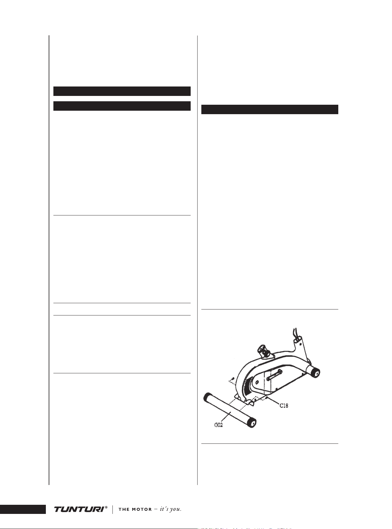
REAR SUPPORT
Mount the rear support to the main frame with
two bolts.
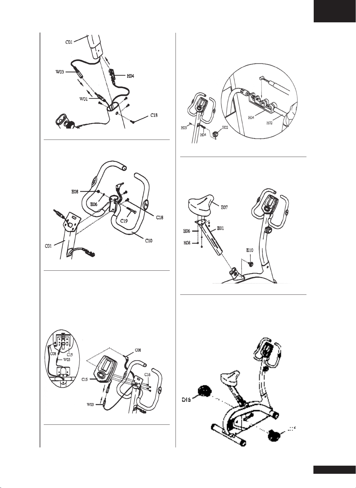
UPRIGHT POST
Connect the upper and lower meter wires together
and push the tension cable into the upright post
prior to tting the upright post to the main frame.
Secure the upright post to the main frame
with four socket bolts.
O WN E R 'S M A NU A L • F 2O O
2
Page 3
G B
3
O WN E R 'S M A NU A L • F 2O O
HANDLEBAR
To secure the handlebar to the upright post, use
two bolts and a bolt a washer and a nut.
Thread A diagonally into the connector box
and t A into B from behind. Then pull C up
before pushing wedge D into gap E. Make sure D
is tightly inserted into E.
SEAT AND SEAT POST
Secure the seat to the seat post with three washers
and three nylon nuts.
Slide the seat post into the frame and secure
the the locking knob.
METER
Pop open the battery cover at the back of the meter
to assemble battery. Connect the meter wire to
meter.
Loosen the screws at the back of the meter
enough to t them into the slot on the steel plate
at the top of the upright post. Slide the screws to
the bottom end of the slot before tightening screws
to secure the meter.
RESISTANCE KNOB
Make sure the display window shows 8 on the
knob. Pull out the connector box from upright
post.
FOOT PEDALS
Fasten the right pedal to the right pedal crank
turning clockwise and left pedal to the left pedal
crank turning anti-clockwise.
The pedals and pedal straps are marked R for
right and L for left.
Page 4

G B
5
O WN E R 'S M A NU A L • F 2O O
U S E
CORRECT EXERCISING POSITION
The seat height should be set so that the middle
part of the foot reaches the pedal with the leg
almost straight and the pedal at its lowest point. To
raise or lower the seat:
1. First turn the locking knob counterclockwise.
2. Then pull the locking knob out so that the seat
tube can be moved freely up and down.
3. When the height is right, let go of the knob.
The seat locks into place.
4. Tighten the locking knob clockwise.
NOTE! Always make sure that the locking knob is
fastened properly before starting to exercise.
The design of the handlebar allows you to
exercise either in an upright position or with the
upper body leaning forward. Remember, however,
always to keep your back straight.
ADJUSTING PEDALLING RESISTANCE
To increase or decrease resistance, turn the
adjustment knob at the top of the handlebar
support tube clockwise (+ direction) to increase
resistance and counterclockwise (- direction) to
decrease resistance. The scale above the knob (1-8)
helps you nd and reset a suitable resistance.
EXERCISING
Working out using an exercise cycle is excellent
aerobic exercise, the principle being that the
exercise should be suitably light, but of long
duration. Aerobic exercise is based on improving
the body’s maximum oxygen uptake, which in turn
improves endurance and tness. The ability of the
body to burn fat as a fuel is directly dependent on
its oxygen- uptake capacity. Aerobic exercise should
above all be pleasant. You should perspire, but you
should not get out of breath during the workout.
You must, for example, be able to speak and not
just pant while pedalling. You should exercise at
least three times a week, 30 minutes at a time, to
reach a basic tness level. Maintaining this level
requires a few exercise sessions each week. Once
the basic condition has been reached, it is easily
improved, simply by increasing the number of
exercise sessions.
Exercise is always rewarding for weight loss,
because it is the only way of increasing the energy
spent by the body. This is why it is always
worthwhile to combine regular exercise with a
healthy diet. A dieter should exercise daily - at rst
30 minutes or less at a time, gradually increasing
the daily workout time to one hour.
You should start slowly at a low pedalling
speed and low resistance, because for an overweight
person strenuous exercise may subject the heart
and circulatory system to excessive strain. As
tness improves, resistance and pedalling speed can
be increased gradually. Exercise efciency can be
measured by monitoring the pulse. The pulse meter
helps you monitor your pulse easily during exercise,
and thus to ensure that the exercise is sufciently
effective but not over-strenuous.
M E T E R
NOTE ! Protect the meter from direct sunlight, as it
may damage the liquid crystal display. Protect the
meter from water and avoid severe impacts, as these
may also damage the meter.
The meter switches on automatically when
you start pedalling or press any key on the meter,
and switches off when you have not pedalled or
pressed a key for about 4 minutes. The readings
accumulated during your workout will be automatically reset when the meter is switched off. You
can also reset the readings by pressing the RE S E T
key.
KEY GUIDE:
SELECT: Select the function to be preset.
: Press to increase the preset values of TI M E ,
DISTA N C E , C A LO RI ES or PU L SE .
: Press to reduce the preset values of T I M E ,
DISTA N C E , C A LO RI ES or PU L SE .
RESET: Reset all the displays to zero except
ACCUM U LA TE D D I ST A NC E .
DETAILS OF OPERATION:
AUTO POWER ON / OFF:
The monitor will be turned on automatically be
pressing any key to start exercise. On the contrary,
it will be turned off automatically if the monitor
does not detect any signal within 256 seconds after
stopping exercising.
AUTO STA R T/STOP:
The moment to start practising, the monitor will
display the progress of the exercise. When stopping
the workout, all the displays will be frozen until the
monitor turns off or begins to exercise again.
TIME :
If TI M E is not preset, it will count up in onesecond increment. TI M E will be displayed by the
last line of LCD.
HOW THE PRESET TIME;
DISTANCE, CALORIE & PULSE:
1. Press SE LE CT key until the window which is
going to be preset is ashing.
2. Press or until desired number is displayed.
3. When start to exercise, the monitor will begin
to count down.
O WN E R 'S M A NU A L • F 2O O
4
Page 5

G B
5
O WN E R 'S M A NU A L • F 2O O
4. It will beep for 12 seconds to indicate the
completion of workout which is preset. Press any
key to stop beeping.
REMARKS
1. It is suggested to preset only one item. If more
than one item is set, the rst to reach the preset
value will sound the alarm.
2. For PU LS E window, the monitor will not beep
after reaching the preset value. The display will
be ashing continuously while actual heartbeat
detected is over the preset value.
3. When pressing SE LECT key, the setting will start
from TIME , DI S T A NC E , CA LO R IE S & PU L S E . To
skip from the setting, please do not press SELE C T
again and wait until the display stops ashing after
programming functions desired. Then, the monitor
will come back to normal and ready to be operated.
ACCUMULATED DISTANCE:
Press and hold RESE T key, the TI M E window
will present AC CU MU LATED DISTA NC E that is
resulted from total distance users have been
exercising. After releasing the key, all the displays
will reset to zero.
SPEE D:
Current speed will be shown by the top line of LC D
when exercising.
DISTANCE :
The distance of each workout will be displayed by
the 4th line of the LCD.
CALO RIE:
The calories burned will ne displayed by the 2nd
line of LCD.
PULS E: (Perfec t pulse s y stem)
To display your current heart rate on the lower
right LCD in beats per minute (BPM). Place the
palms of your hands on the both of the contact
pads and the monitor will show up your current
beat rate in beat per minute (BPM) on the LCD
display. (Please see the drawing below.)
NOTE:
1. If pulse value is not preset, the monitor will
show the default value at 90BPM.
2. If no Pulse Signal input within 16 seconds,
the display will indicate ”P”. It is a power saving
device. Customers can press the up & down keys to
restart Pulse function.
M A I N T E N A N C E
The equipment requires very little maintenance.
Check, however, from time to time that all screws
and nuts are tight. Clean the cycle with a damp
cloth. Do not use solvents.
NOTE! Never remove the protective covers.
NOTE! The brake forms a magnetic eld
which may damage the mechanism of a watch or
the magnetic identication tape of a credit or cash
card if they come into immediate contact with the
magnets. Never attempt to detach or remove the
magnet fork of the magnetic brake.
If you notice a malfunction during use,
contact the dealer. Always give the model and
serial number of your device, please state also
the nature of the problem conditions of use and
purchase date.
In spite of continuous quality control,
individual defects and malfunctions may occur
in individual components. It is in most cases
unnecessary to take the whole cycle for repair, as it
is usually sufcient to replace the defective part.
CHANGING BATTERIES
If the meter display fades considerably or
completely, change the batteries.
Detach the lid of the battery casing at the back
of the meter and remove the old batteries. Place
the new batteries in the holder (2 x 1.5 V AA) and
push the battery casing lid back into place.
T R A N S P O R T A N D S T O R A G E
The cycle is easy to move by pushing along on the
integrated transport wheels. Tilt the cycle from the
front and push along the oor on the wheels at the
front support.
To prevent malfunctioning of the cycle, store
in a dry place with as little temperature variation as
possible, protected from dust.
D I M E N S I O N S
Length......87 cm / 34” Width .......61 cm / 24”
Height....127 cm / 50” Weight ... 31 kg / 69 lbs
All Tunturi models are designed to meet the
electromagnetic compatibility directive, EMC and
are afxed with the CE conformity marking.
NOTE! The instructions must be followed
carefully in the assembly, use and maintenance
of your equipment. The warranty does not
cover damage due to negligence of the assembly,
adjustment and maintenance instructions described
herein. Changes or modications not expressly
approved by Tunturi Oy Ltd will void the user's
authority to operate the equipment!
Due to our continuous policy of product
development we reserve the right to change
specications without notice.
Page 6

36
37
Page 7

37
F 2 O O
B01 Main frame 1
C01 Upright post 1
C07 Hand Pulse Sensor 2
C08 Hand Pulse wire 1
C09 M4x18 DIN 7985 Screw 2
C10 Handle Bar 1
C11 Handle Sponge 2
C12 End cap for handle bar 2
C13 - 1/2” Cap 1
C15 EU Meter 1
C15 GB/US Meter 1
C16 M5x8 DIN 7985 Screw 4
*C18 M8x15 DIN 912 Socket bolt 8
*C19 M8x60 DIN 603 Bolt 1
D02 Shaft 1
D03 Ball bearing 6004 ZZ 2
D04 C-clip (S-20) 3
D05 Fly wheel 1
D06 Belt 1
D07 Magnet 1
D08 Beltwheel bracket 1
D09 M8 DIN 127 Spring Washer 4
D10 Crank (R) 1
D11 Crank (L) 1
D12 M8x20mm Hexagonal nut 2
D13 M8x20 DIN 933 Hexagonal bolt 4
D14 Crank cover 2
D15 Pedal (R) 1
D16 Pedal (L) 1
D17 Pedal strap (R) 1
D18 Pedal strap (L) 1
D19 Nut 1
E01 Seat post 1
*E06 M8 DIN 125 Washer 4
E07 Seat 1
*E08 M8 DIN 985 Nylon nut 4
E10 Locking knob 1
E11 Locking nut 1
E13 Seat post sleeve 1
E15 M4x10 DIN 7985 Screw 2
E16 M4 DIN 934 Nut 2
E19 - 3/8” Nut 2
F01 Magn. resistance system 1
G02 Rear support tube 1
G06 - 3” End cap 4
G12 Transportation wheel 2
G14 Rivet 4
H02 Tension knob 1
H03 - M5x20 mm Screw
1 H04 Tension cable 1
R01 Dancing plate 1
SPARE PART LIST
ERSATZTEILLISTE
LISTE DES PIÈCES DÉTACHÉES
JUEGO DE HERREMIENTAS
UTENSILI
GEREEDSCHAP SET
MONTERINGSSATS
VARAOSALUETTELO
R03 Ball bearing 6204 ZZ 1
R05 Spring 1
R08 Dancing plate xture 1
S01 Right cover 1
S02 Left cover 1
S03 Front cover 1
S04 Rear cover 1
S05 M4x12DIN7500C Self tapping screw 5
S06 M4x16DIN7500C Self tapping screw 6
W01 Sensor wire 600mm 1
W02 M3x8 DIN7504N Screw 2
W03 Meter wire 1000mm 1
* 553 0015 Assembly kit (incl. *) 1
* 553 101 Screw - shaped 1
* 553 100 88 Multi purp. wrench 1
* 556 031 Allen key 5 mm 1
- 583 0010 Owner’s manual 1
Page 8

www.tunturi.com
TUNTURI OY LTD
P.O.BOX 750, FIN-20361
Turku, Finland
Tel. +358 (0)2 513 31
Fax +358 (0)2 513 3323
www.tunturi.com
 Loading...