

Page 1

Operator’s Manual
4-Cycle Backpack Blower
TB4BP
P/N 769-03148C (09/07)
For service call 1-800-828-5500, or 1-800-668-1238 in Canada to
obtain a list of authorized service dealers near you. For more details
about your unit, visit our website at www.troybilt.com.
DO NOT RETURN THE UNIT TO THE RETAILER. PROOF OF
PURCHASE WILL BE REQUIRED FOR WARRANTY SERVICE.
THIS PRODUCT IS COVERED BY ONE OR MORE U.S. PATENTS.
OTHER PATENTS PENDING.
Service on this unit both within and after the warranty period should be
performed only by an authorized and approved service dealer.
Copy the serial number here:
Copy the model and parent part number here:
All information, illustrations, and specifications in this manual are based on
the latest product information available at the time of printing. We reserve
the right to make changes at any time without notice.
Copyright© 2007 MTD SOUTHWEST INC, All Rights Reserved.
TABLE OF CONTENTS
Service Information . . . . . . . . . . . . . . . . . . . . . . . . . . . . . . . . . . . .1
Rules for Safe Operation . . . . . . . . . . . . . . . . . . . . . . . . . . . . . . . .2
Know Your Unit . . . . . . . . . . . . . . . . . . . . . . . . . . . . . . . . . . . . . . .5
Assembly Instructions . . . . . . . . . . . . . . . . . . . . . . . . . . . . . . . . . .6
Oil and Fuel . . . . . . . . . . . . . . . . . . . . . . . . . . . . . . . . . . . . . . . . . .8
Starting/Stopping Instructions . . . . . . . . . . . . . . . . . . . . . . . . . . . .9
Operating Instructions . . . . . . . . . . . . . . . . . . . . . . . . . . . . . . . . .10
Maintenance and Repair Instructions . . . . . . . . . . . . . . . . . . . . .11
Cleaning and Storage . . . . . . . . . . . . . . . . . . . . . . . . . . . . . . . . . .13
Troubleshooting . . . . . . . . . . . . . . . . . . . . . . . . . . . . . . . . . . . . . .14
Specifications . . . . . . . . . . . . . . . . . . . . . . . . . . . . . . . . . . . . . . . .15
Warranty Information . . . . . . . . . . . . . . . . . . . . . . . . . . . . . . . . . .18
Parts List . . . . . . . . . . . . . . . . . . . . . . . . . . . . . . . . . . . . . . . . . .E18
SAVE THESE INSTRUCTIONS
Before beginning, locate the unit’s model plate. It lists the model and
serial numbers of your unit. Refer to the sample plate below and
copy the information for future reference.
MODEL :
S/N :
ITEM :
Page 2

2
• Add fuel in a clean, well-ventilated area outdoors where there are
no sparks or flames. Slowly remove the fuel cap only after
stopping engine. Do not smoke while fueling. Wipe up any spilled
fuel from the unit immediately.
• Avoid creating a source of ignition for spilled fuel. Do not start
the engine until fuel vapors dissipate.
• Move the unit at least 30 feet (9.1 m) from the fueling source and site
before starting the engine. Do not smoke. Keep sparks and open
flames away from the area while adding fuel or operating the unit.
WHILE OPERATING
• Never start or run the unit inside a closed room or building.
Breathing exhaust fumes can kill. Operate this unit only in a wellventilated outdoor area.
• Wear safety glasses or goggles that are marked as meeting ANSI
Z87.1 standards and are marked as such. Wear ear/hearing
protection when operating this unit.
• Never run the unit without the the proper equipment attached.
• To reduce the risk of hearing loss associated with sound level(s),
always wear ear/hearing protection when operating this unit.
• Wear heavy long pants, boots, gloves, and a long sleeve shirt. Do
not wear loose clothing, jewelery, short pants, sandals or go
barefoot. Secure hair above shoulder level.
• To avoid static electricity shock, do not wear rubber gloves or
any other insulated gloves while operating this unit.
• Use the unit only in daylight or good artificial light.
• Keep outside surfaces free from oil and fuel.
• Avoid accidental starting. Be in the starting position whenever
pulling the starter rope. The operator and unit must be in a stable
position while starting. Refer to Starting/Stopping Instructions.
READ ALL INSTRUCTIONS BEFORE OPERATING
• Read the instructions carefully. Be familiar with the controls and
proper use of the unit.
• Read this operating instruction manual carefully. Be thoroughly
familiar with the controls and the proper use of the equipment.
Know how to stop the unit and disengage the controls quickly.
• Do not operate this unit when tired, ill, or under the influence of
alcohol, drugs, or medication.
• Never allow children to operate the equipment. Never allow
adults unfamiliar with the instructions to use the unit. Never allow
adults to operate the equipment without proper instruction.
• All guards and safety attachments must be installed properly
before operating the unit.
SPECIAL SAFETY WARNINGS FOR GAS ENGINES
• Store fuel only in containers specifically designed and approved
for the storage of such materials.
• Always stop the engine and allow it to cool before filling the fuel tank.
Never remove the cap of the fuel tank, or add fuel, when the engine
is hot. Never operate the unit without the fuel cap securely in place.
Loosen the fuel tank cap slowly to relieve any pressure in the tank.
• IMPORTANT SAFETY INSTRUCTIONS •
Read the Operator’s Manual and follow all warnings and safety instructions. Failure to do so can result in serious injury to the
operator and/or bystanders.
FOR QUESTIONS, CALL 1-800-828-5500 IN U.S. OR 1-800-668-1238 in CANADA
The purpose of safety symbols is to attract your attention to possible
dangers. The safety symbols, and their explanations, deserve your
careful attention and understanding. The safety warnings do not by
themselves eliminate any danger. The instructions or warnings they
give are not substitutes for proper accident prevention measures.
NOTE: Advises you of information or instructions vital to the
operation or maintenance of the equipment.
SAFETY ALERT:
Indicates danger, warning or
caution. Attention is required in order to avoid serious
personal injury. May be used in conjunction with other
symbols or pictographs.
DANGER:
Failure to obey a safety warning will result
in serious injury to yourself or to others. Always follow
the safety precautions to reduce the risk of fire, electric
shock and personal injury.
WARNING:
Failure to obey a safety warning can
result in injury to yourself and others. Always follow the
safety precautions to reduce the risk of fire, electric
shock and personal injury.
CAUTION:
Failure to obey a safety warning may
result in property damage or personal injury to yourself
or to others. Always follow the safety precautions to
reduce the risk of fire, electric shock and personal injury.
RULES FOR SAFE OPERATION
SYMBOL MEANING
WARNING:
When using the unit, you must follow the
safety rules. Please read these instructions before operating
the unit in order to ensure the safety of the operator and any
bystanders. Please keep these instructions for later use.
WARNING:
Gasoline is highly flammable, and its
vapors can explode if ignited. Take the following
precautions:
SPARK ARRESTOR NOTE
NOTE: For users on U.S. Forest Land and in the states of
California, Maine, Oregon and Washington. All U.S. Forest Land
and the state of California (Public Resources Codes 4442 and 4443),
Oregon and Washington require, by law that certain internal
combustion engines operated on forest brush and/or grass-covered
areas be equipped with a spark arrestor, maintained in effective
working order, or the engine be constructed, equipped and
maintained for the prevention of fire. Check with your state or local
authorities for regulations pertaining to these requirements. Failure to
follow these requirements could subject you to liability or a fine. This
unit is factory equipped with a spark arrestor. If it requires
replacement, ask your LOCAL SERVICE DEALER to install the
Accessory Part #753-05297 Spark Arrestor Kit.
CALIFORNIA PROPOSITION 65 WARNING
WARNING
THE ENGINE EXHAUST FROM THIS PRODUCT CONTAINS
CHEMICALS KNOWN TO THE STATE OF CALIFORNIA TO
CAUSE CANCER, BIRTH DEFECTS OR OTHER
REPRODUCTIVE HARM.
Page 3

3
RULES FOR SAFE OPERATION
• Do not set unit on any surface except a clean, hard area while
engine is running. Debris such as gravel, sand, dust, grass, etc.
could be picked up by the air intake and thrown out by the
discharge opening, damaging unit, property, or causing serious
injury to bystanders or operator.
• Use the right tool. Only use this tool for its intended purpose.
• Do not force unit. It will do the job better and with less likelihood
of injury at a rate for which it was designed.
• Do not overreach or use from unstable surfaces such as ladders,
trees, steep slopes, rooftops, etc. Always keep proper footing
and balance.
• Always hold the unit with a firm grip when operating.
• Keep hands, face, and feet away from all moving parts. Do not
touch or try to stop the impeller when it is rotating. Do not
operate without guards in place.
• Do not put any object into openings. Do not use with any
opening blocked; keep free of dirt, debris, and anything that may
reduce the air flow.
• Do not touch the engine or muffler. These parts get extremely
hot from operation, even after the unit is turned off.
• Do not operate the engine faster than the speed needed to do
the job. Do not run the engine at high speed when not in use.
• Always stop the engine when operation is delayed or when
walking from one location to another.
• Stop the engine for maintenance, repair, to install or remove the
blower tubes. The unit must be stopped and the impeller no
longer turning to avoid contact with the rotating blades.
• If you strike or come into contact with a foreign object, stop the
engine immediately and check for damage. Do not operate
before repairing damage. Do not operate the unit with loose or
damaged parts.
• Use only replacement parts recommended for this tool that are
sold by a Troy-Bilt outlet. Use of any replacement parts purchased
elsewhere may be hazardous, and will also void your warranty.
• Never use this unit for spreading chemicals, fertilizers or other
substances which may contain toxic materials.
• To reduce fire hazard, replace faulty muffler and spark arrestor.
Keep the engine and muffler free from grass, leaves, excessive
grease or carbon build up.
• Turn the engine off and disconnect the spark plug for
maintenance or repair.
• Never point the blower or blowing debris in the direction of
people, animals, or in the direction of windows. Always direct the
blowing debris away from people, animals, and windows. Use
extra caution when blowing debris near solid objects such as
trees, automobiles, walls, etc.
OTHER SAFETY WARNINGS
• Always disconnect the spark plug before performing
maintenance or accessing movable parts. See Replacing the
Spark Plug.
• Never store the unit, with fuel in the tank, inside a building where
fumes may reach an open flame (pilot lights, etc.) or sparks
(switches, electrical motors, etc.).
• Allow the engine to cool before storing or transporting. Be sure
to secure the unit while transporting.
• Store the unit in a dry place, secured, or at a height to prevent
unauthorized use or damage. Keep out of the reach of children.
• Never douse or squirt the unit with water or any other liquid.
Keep handles dry, clean, and free from debris. Clean after each
use, see Cleaning and Storage instructions.
• Keep these instructions. Refer to them often and use them to
instruct other users. If you loan this unit to others, also loan
these instructions to them.
SPECIAL NOTE: Exposure to vibrations through prolonged use of
gasoline powered hand tools could cause blood vessel or nerve
damage in the fingers, hands, and joints of people prone to
circulation disorders or abnormal swelling. Prolonged use in cold
weather has been linked to blood vessel damage in otherwise
healthy people. If symptoms occur such as numbness, pain, loss
of strength, change in skin color or texture, or loss of feeling in the
fingers, hands or joints, discontinue use of this tool and seek
medical attention. A reduced vibration system does not guarantee
avoidance of these problems. Users who operate power tools on a
regular basis must closely monitor their physical condition and the
condition of this tool.
SAVE THESE INSTRUCTIONS
Page 4
4
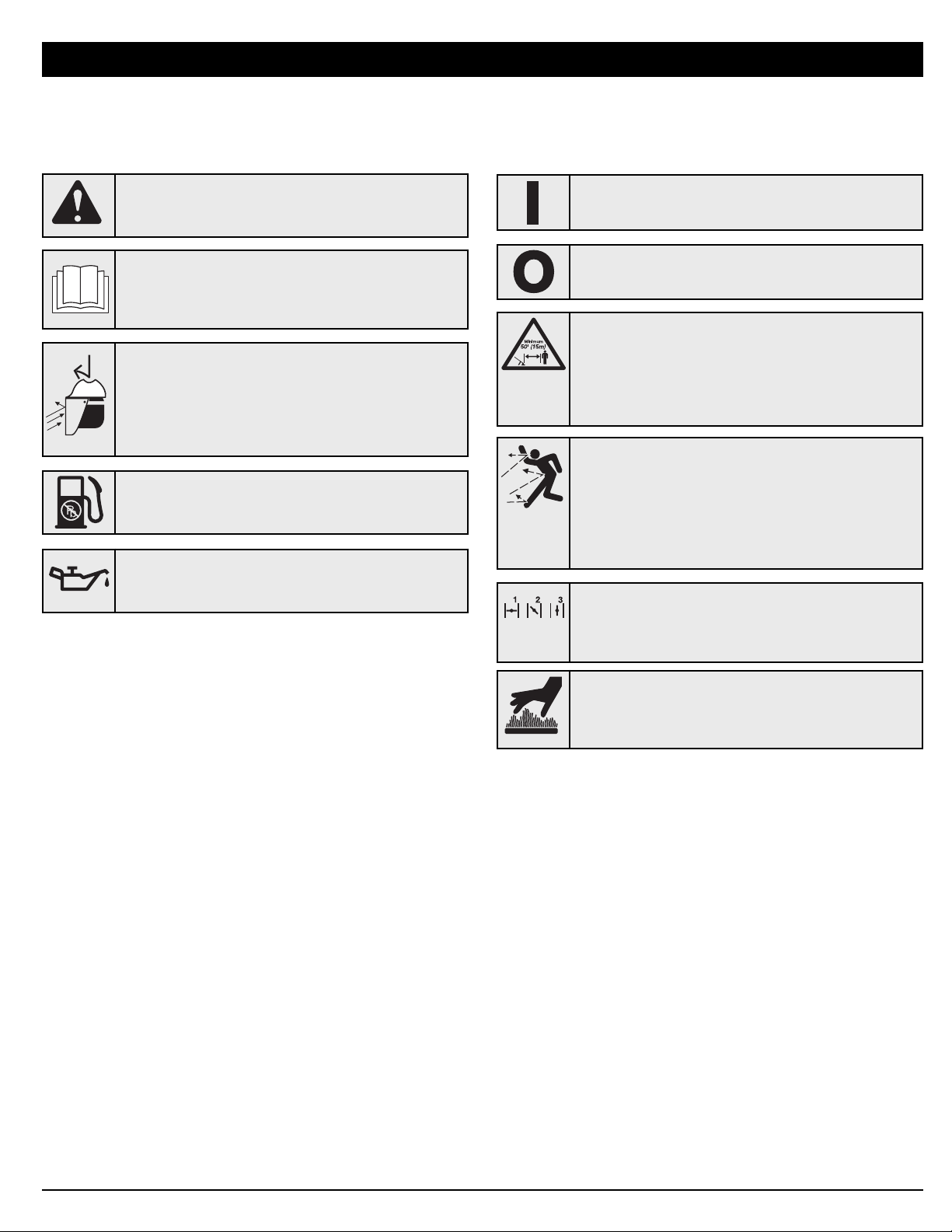
SAFETY AND INTERNATIONAL SYMBOLS
This operator's manual describes safety and international symbols and pictographs that may appear on this product.
Read the operator's manual for complete safety, assembly, operating, maintenance,` and repair information.
RULES FOR SAFE OPERATION
• WARNING: READ OPERATOR'S MANUAL
Read the operator’s manual(s) and follow all warnings
and safety instructions. Failure to do so can result in
serious injury to the operator and/or bystanders.
• KEEP BYSTANDERS AWAY
WARNING:
Thrown objects and loud noise can
cause severe eye injury and hearing loss. Wear eye
protection meeting ANSI Z87.1 standards and ear
protection when operating this unit. Use a full face
shield when needed.
SYMBOL MEANING
• THROWN OBJECTS CAN CAUSE SEVERE
INJURY
WARNING:
Thrown objects and loud noise can
cause severe eye injury and hearing loss. Wear eye
protection meeting ANSI Z87.1 standards and ear
protection when operating this unit. Use a full face
shield when needed.
• SAFETY ALERT SYMBOL
Indicates danger, warning or caution. May be used in
conjunction with other symbols or pictographs.
SYMBOL MEANING
• WEAR EYE AND HEARING PROTECTION
WARNING:
Thrown objects and loud noise can
cause severe eye injury and hearing loss. Wear eye
protection meeting ANSI Z87.1 standards and ear
protection when operating this unit. Use a full face
shield when needed.
•OIL
Refer to operator’s manual for the proper type of oil.
• UNLEADED FUEL
Always use clean, fresh unleaded fuel.
• ON/OFF STOP CONTROL
OFF or STOP
• ON/OFF STOP CONTROL
ON / START / RUN
• HOT SURFACE WARNING
Do not touch a hot surface. You may get burned.
These parts get extremely hot from operation. They
remain hot for a short time after the unit is turned off.
• CHOKE CONTROL
1. • FULL choke position
2. • PARTIAL choke position
3. • RUN choke position
Page 5

5
Stand
Trigger Lock
Starter Rope
Handle
Waist
Support
Clip
Muffler
Air Filter Cover
KNOW YOUR UNIT
Primer Bulb
Oil Fill Plug
Suspension System
Gas Tank
Choke Lever
Waist
Support
Gas Cap
Trigger
Blower
Tube
Shoulder
Support Buckle
Throttle Grip
Elbow Tube
Throttle
Cables
Nozzle
Shoulder Support
Page 6
6
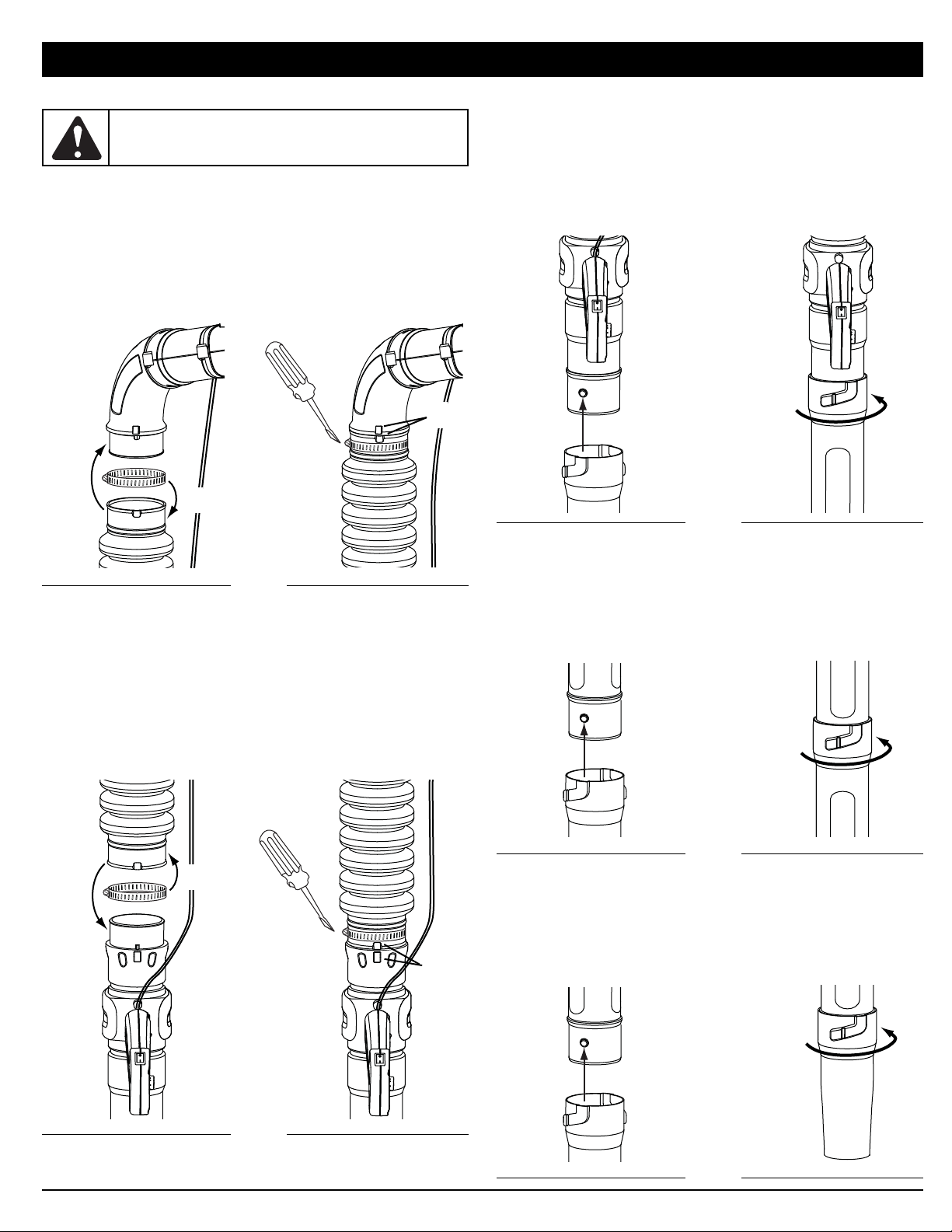
ASSEMBLING THE BLOWER TUBE
Installing the Flex Tube
1. Place a hose clamp over the end of the Flex Tube (Fig. 1A).
2. Slide the end of the Flex Tube with the clamp on it over the
elbow tube (Fig. 1B).
3. Align the bump on the Flex Tube with the bump on the elbow
tube (Fig. 1C).
4. Tighten the screw on the hose clamp to secure the Flex Tube
to the elbow tube (Fig. 1D).
Installing the Upper Blower Tube
1. Place a hose clamp over the other end of the Flex Tube (Fig. 2, A).
2. Slide the end of the hose with the clamp on it over the top end
of the upper blower tube (Fig. 2, B).
3. Align the bump on the Flex Tube with the bump on the upper
blower tube (Fig. 2, C).
4. Tighten the screw on the hose clamp to secure the Flex Tube
to the upper blower tube (Fig. 2, D).
Installing the Lower Blower Tubes and Nozzle
1. Align the bump slot on the end of the first lower blower tube
with the bump on the bottom end of the upper blower tube
(Fig. 3, A).
2. Insert the bump on the upper blower tube into the bump slot
on the tube extension (Fig. 3, A).
3. Twist the extension tube clockwise around the upper blower tube
until the handle tube bump locks into place (Fig. 3, B).
4. Align the bump slot on the end of the second lower blower tube with
the bump on the bottom end of the first lower blower tube (Fig. 4, A).
5. Insert the bump on the first lower blower tube into the bump
slot on the second lower blower tube (Fig. 4, A).
6. Twist the second lower blower tube clockwise around the first
lower blower tube until the second lower blower tube bump
locks into place (Fig. 4, B).
7. Align the bump slot on the top end of the nozzle with the bump
on the bottom end of the second lower blower tube (Fig. 5, A).
8. Insert the bump on the second lower blower tube into the
bump slot on the nozzle (Fig. 5, A).
9. Twist the nozzle clockwise around the second lower blower tube
until the nozzle bump locks into place (Fig. 5, B).
ASSEMBLY INSTRUCTIONS
WARNING:
To avoid serious personal injury and
damage to the unit, shut the unit off before removing or
installing the blower tube.
Fig. 1
A
B
D
Fig. 2
A
B
D
Fig. 3
A
B
C
C
Fig. 4
A
B
Fig. 5
A
B
Page 7

7
WARNING:
To avoid serious personal injury, make
sure that the blower tubes are locked in place or firmly
installed.
ASSEMBLY INSTRUCTIONS
The completed blower tube should look like Figure 6.
Fig. 6
Adjusting the Handle
1. Rotate the throttle grip counterclockwise around the blower
tube until it is pointing directly downward (Fig. 7, A).
2. Pull or push the throttle grip along the handle tube until its
distance from the backpack blower is comfortable (Fig. 7, B).
3. Align the throttle grip with the slot closest to the comfortable
place and rotate the throttle grip clockwise into the upright
position (Fig. 8).
Fig. 7
A
B
Fig. 8
Flex Tube
Hose Clamp
Elbow Tube
Upper Blower Tube
First Lower
Blower Tube
Second Lower
Blower Tube
Nozzle
Throttle Cables
Hose Clamp
WARNING:
Do not rotate the handle clockwise to
adjust. This may cause the throttle cables to
disconnect from the throttle grip or the engine.
Throttle Grip
On/Off Switch
Page 8

8
OIL AND FUEL INFORMATION
RECOMMENDED OIL TYPE
Using the proper type and weight of oil in the crankcase is extremely
important. Check oil before each use while the engine is cold and
change the oil every 25 hours of operation. Failure to use the correct
oil, or using dirty oil, can cause premature engine wear and failure.
Use a high-quality SAE 30 weight oil of API (American Petroleum
Institute) service class SF, SG, SH.
ADDING OIL TO CRANKCASE: INITIAL USE
NOTE: This unit is shipped without
oil. In order to avoid damage
to the unit, put oil in the
crankcase before you
attempt to start the unit.
Your unit is supplied with one 3.04
fluid oz. (90 ml.) bottle of SAE 30 SF,
SG, SH oil (Fig. 9).
NOTE: Save the bottle of oil. It can
be used to measure the
correct amount during
future oil changes (Fig. 9).
See Changing the Oil.
1. Unscrew the top of the bottle
of oil and remove the paper
seal covering the opening.
Replace the top. Next, cut the
tip off the funnel spout (Fig. 9).
2. Remove the oil fill plug from
the crankcase (Fig. 10).
3. Tilt the unit backwards 30°
(Fig. 11).
4. Pour the entire bottle of oil
into the oil fill hole (Fig. 11).
NOTE: Never add oil to the fuel or
fuel tank.
5. Wipe up any oil that may have
spilled and reinstall the oil fill
plug.
Check oil before each use while the
engine is cold and change the oil
every 25 hours of operation. Refer to
Checking the Oil Level.
CHECKING THE OIL LEVEL
Check the oil only when the engine is
off and cool.
1. Place the unit on its stand on a level surface.
2. Remove the oil fill plug from the crankcase (Fig. 10).
3. Look into the oil fill hole (Fig. 10). If the oil level comes up to
the first thread, then the oil is full (Fig. 12). If it does not, fill
with oil until it does.
Fig. 9
Funnel
Spout
RECOMMENDED FUEL TYPE
Old fuel is the primary reason for improper unit performance. Be
sure to use fresh, clean, unleaded gasoline.
NOTE: This is a four cycle engine. In order to avoid damage to the
unit, do not mix oil with gasoline.
Definition of Blended Fuels
Today's fuels are often a blend of gasoline and oxygenates such as
ethanol, methanol or MTBE (ether). Alcohol-blended fuel absorbs
water. As little as 1% water in the fuel can make fuel and oil
separate or form acids when stored. Use fresh fuel (less than 60
days old), when using alcohol-blended fuel.
Using Blended Fuels
If you choose to use a blended fuel, or its use is unavoidable,
follow recommended precautions:
• Always use fresh unleaded gasoline
• Use the fuel additive STA-BIL® or an equivalent
• Drain tank and run the engine dry before storing unit
Using Fuel Additives
The use of fuel additives, such as STA-BIL® Gas Stabilizer or an
equivalent, will inhibit corrosion and minimize the formation of gum
deposits. Using a fuel additive can keep fuel from forming harmful
deposits in the carburetor for up to six (6) months. Add 0.8 oz. (23 ml.)
of fuel additive per gallon of fuel according to the instructions on the
container. NEVER add fuel additives directly to the unit's gas tank.
FUELING THE UNIT
1. Remove the fuel cap.
2. Place the gas container’s spout into the fill hole on the fuel
tank (Fig. 13) and fill the tank.
NOTE: Do not overfill the tank.
3. Wipe up any gasoline that may have spilled.
4. Reinstall the fuel cap.
5. Move the unit at least 30 ft. (9.1 m) from the fueling source and
site before starting the engine.
NOTE: Dispose of the old gasoline in accordance to Federal, State
and Local regulations.
Fig. 11
WARNING:
Add fuel in a clean, well ventilated
outdoor area. Wipe up any spilled fuel immediately.
Avoid creating a source of ignition for spilt fuel. Do not
start the engine until fuel vapors dissipate.
WARNING:
Gasoline is extremely flammable. Ignited
vapors may explode. Always stop the engine and allow
it to cool before filling the fuel tank. Do not smoke while
filling the tank. Keep sparks and open flames at a
distance from the area.
WARNING:
Remove fuel cap slowly to avoid injury
from fuel spray. Never operate the unit without the fuel
cap securely in place.
WARNING:
OVERFILLING OIL CRANKCASE MAY
CAUSE SERIOUS PERSONAL INJURY. Check and
maintain the proper oil level in the crank case; it is
important and cannot be overemphasized. Check the
oil before each use while the engine is cold and change
it as needed. See Changing the Oil.
Oil Fill Plug
Oil Fill Hole
O-Ring
Fig. 10
Fig. 13
Fuel Tank
Gas Can
Spout
Fig. 12
Oil Full Line
Fill Level
30°
Page 9

9
Trigger
STARTING INSTRUCTIONS
STOPPING INSTRUCTIONS
1. Release your hand from the trigger. Allow the engine to cool
down by idling.
2. Press the On/Off Stop Control switch in the OFF (O) position
and hold until the engine comes to a complete stop (Fig. 15).
Starter Rope
Fig. 15
STARTING/STOPPING INSTRUCTIONS
Fig. 16
Fig. 14
Primer
Bulb
Choke Lever
WARNING:
Operate this unit only in a wellventilated outdoor area. Carbon monoxide exhaust
fumes can be lethal in a confined area.
WARNING:
Avoid accidental starting. Make sure
you are in the starting position when pulling the starter
rope (Fig. 16). To avoid serious injury, the operator and
unit must be in a stable position while starting.
To avoid serious personal injury, make sure that the
blower tube is locked in place or firmly installed.
1. Check the oil level in the crankcase. Refer to Checking
the Oil Level.
2. Fill the fuel tank with fresh, clean unleaded gasoline.
Refer to Fueling the Unit.
3. Fully press and release the primer bulb 10 times, slowly.
Some amount of fuel should be visible in the primer
bulb and fuel lines (Fig. 14). If you can’t see fuel in the
bulb, press and release the bulb as many times as it
takes before you can see fuel in it.
4. Place the choke lever in Position 1 (Fig. 14).
NOTE: The unit should be started in idle. Do not squeeze
the trigger while starting (Fig. 15).
5. Crouch in the starting position and pull the starter rope
out about 4 inches, then pull 4 times in smooth and
rapid pulls to start engine (Fig. 16).
IF...
the engine does not start, place the choke lever in
Position 2 (Fig. 14) and pull 4 times in smooth and rapid
pulls to start engine.
6. Place the choke lever in Position 2 (Fig. 14) and allow
the engine to warm up for 5–10 seconds.
7. Place the choke lever in Position 3 (Fig. 14). The unit is
ready for use.
IF...
the engine does not start, follow steps 3 through 7 again.
HOT
RESTART: If the unit is already hot, place the choke
lever in Position 3 and pull the starter rope to restart.
The unit should be started in idle. Do not squeeze the
trigger while starting (Fig. 15).
On/Off Switch
Trigger Lock
Page 10

10
OPERATING INSTRUCTIONS
ADJUSTING THE SUSPENSION SYSTEM
1. Place the unit’s shoulder supports over the shoulders while
the unit is behind you.
2. Close the suspension system’s waist support by sliding the
waist support clips together (Fig. 17, A).
NOTE: Make sure the weight of the unit is supported on the hips
by the waist support (Fig. 18, A).
3. If weight is not on hips, loosen the shoulder supports (Fig. 19,
A) and pull the waist support handle (Fig. 18, B) to tighten.
Adjust until the unit’s weight rests on the hips.
4. Pull the shoulder support handles to tighten the shoulder
supports (Fig. 17, B).
Releasing the Suspension System
1. To release the shoulder supports, pull up on bottom tab of the
shoulder support buckles (Fig. 19, A).
2. Squeeze the top and bottom of the waist support clips to
release the waist support (Fig. 19, B).
HOLDING THE BLOWER
Before operating the unit, stand in the operating position (Fig. 20).
Check for the following:
• Operator is wearing proper clothing, such as boots, safety
glasses or goggles, ear/hearing protection, gloves, long pants
Fig. 20
WARNING:
To avoid serious personal injury, wear
goggles or safety glasses at all times when operating
this unit. Wear a face mask or dust mask in dusty
locations.
and long sleeve shirt.
• If the conditions are dusty, the operator is wearing a dust mask
or face mask.
• The unit is in good working condition.
• The tubes are in place and secure.
OPERATING TIPS
• Assure the unit is not directed at anybody or any loose debris
before starting the unit.
• Verify that the unit is in good working condition. Make sure the
tubes are in place and secure.
• Always hold the unit securely when operating.
• To reduce the risk of hearing loss associated with sound level(s),
hearing protection is required.
• Operate power equipment only at reasonable hours— not early in the
morning or late at night when people might be disturbed. Comply
with times listed in local ordinances. Usual recommendations are 9:00
am to 5:00 pm, Monday through Saturday.
• To reduce noise levels, limit the number of pieces of equipment
used at any one time.
• To reduce noise levels, operate power blowers at the lowest
possible speed to do the job.
• Check your equipment before operation, especially the muffler,
air intakes and air filters.
• Use rakes and brooms to loosen debris before blowing.
• In dusty conditions, slightly dampen surfaces or use a mister
attachment when water is available.
• Conserve water by using power blowers instead of hoses for
many lawn and garden applications, including areas such as
screens, patios, grills, porches, and gardens.
• Watch out for children, pets, open windows or freshly washed
cars, and blow debris safely away.
• Use the full blower nozzle extension so the air stream can work
close to the ground.
• Clean up after using blowers and other equipment. Dispose of
debris appropriately.
• Use the trigger lock (Fig. 15) to keep the trigger depressed while
operating to make continuous operation easier.
APPLICATIONS
1 Use the blower for trees, shrubs, flower beds and hard-to-
clean areas.
2. Use the unit around buildings and for other normal cleaning
procedures.
3. Use the blower around walls, overhangs, fences and screens.
Fig. 17
A
B
B
WARNING:
To prevent serious personal injury or
damage to the unit, make sure blower tubes are in
place before you operate the unit.
Fig. 19
B
A
A
Fig. 18
B
A
A
Page 11

11
AIR FILTER MAINTENANCE
Cleaning the Air Filter
Clean and re-oil the air filter every 25 hours of operation. It is an important
item to maintain. Failure to maintain your air filter properly can result in
poor performance or can cause permanent damage to your engine.
1. Open the air filter cover. Push the locking tab on the under side of
the cover inward. Then pull the air filter cover out and up. (Fig. 23).
2. Remove the air filter (Fig. 24).
3. Wash the filter in detergent and
water (Fig. 25). Rinse the filter
thoroughly and allow it to dry.
4. Apply enough clean SAE 30 motor
oil to lightly coat the filter (Fig. 26).
5. Squeeze the filter to spread and
remove excess oil (Fig. 27).
6. Replace the filter (Fig. 24).
NOTE: If the unit is operated without
the air filter, you will VOID the
warranty.
MAINTENANCE AND REPAIR INSTRUCTIONS
CHANGING THE OIL
Change the oil every 25 hours of operation. Change the oil while
the engine is still warm. The oil will flow freely and carry away more
impurities.
1. Remove the oil fill plug.
2. Pour the oil out of the oil fill
hole and into a container by
tipping the unit to the side
(Fig. 21). Allow ample time
for complete drainage.
3. Wipe up any oil residue on
the unit and clean up any
oil that may have spilled.
Dispose of the oil according
to Federal, State and local
regulations.
4. Tilt the unit backwards 30°
(Fig. 22).
5. Refill the crankcase with
3.04 fluid ounce (90 ml) of
SAE 30 SF, SG, SH oil.
NOTE: Use the bottle and
spout saved from initial use to measure the correct
amount of oil. The top of the label on the bottle measures
approximately 3.04 ounces (90 ml) (Fig. 22). Check the
level, See Checking the Oil Level. If the level is low, add a
small amount of oil and recheck. Do not overfill (Fig. 22).
6. Replace the oil fill plug.
Fig. 21
Fill Level
Fig. 22
Fig. 25
Fig. 23
Fig. 24
WARNING: Wear gloves to prevent injury when
handling unit.
WARNING:
To avoid serious personal injury, always
turn the unit off and allow it to cool before you clean or
service it.
Locking Tab
Ta bs
Back Plate
Air Filter
Locking
Ta b
Air Filter Cover
WARNING:
To prevent serious injury, never perform
maintenance or repairs with unit running. Always
service and repair a cool unit. Disconnect the spark
plug wire to ensure that the unit cannot start. See
Replacing the Spark Plug.
FREQUENCY MAINTENANCE REQUIRED SEE
Before using
Fill fuel tank with fresh fuel
Check oil while the engine is cold
p 8
p 8
Every 25 hrs
Change oil
Clean and re-oil air filter
Check rocker arm clearance and adjust
Check spark plug condition and gap
p 11
p 11
p 12
p 13
Every 50 hrs Clean spark arrestor p 13
MAINTENANCE SCHEDULE
Perform these required maintenance procedures at the frequency
stated in the table. These procedures should also be a part of any
seasonal tune-up.
NOTE: Some maintenance procedures may require special tools
or skills. If you are unsure about these procedures take
your unit to a Troy-Bilt or other qualified service dealer.
NOTE: Maintenance, replacement, or repair of the emission
control devices and system may be performed by a TroyBilt or other qualified service dealer.
In order to assure peak performance of your engine, inspection of
the engine exhaust port may be necessary after 50 hours of
operation. If you notice lost RPM, poor performance or general lack
of acceleration, this service may be required. If you feel your engine
is in need of this inspection, refer service to a Troy-Bilt or other
qualified service dealer for repair. DO NOT attempt to perform this
process yourself as engine damage may result from contaminants
involved in the cleaning process for the port.
30°
Page 12

12
ROCKER ARM CLEARANCE
This requires disassembly of the engine. If you feel unsure or unqualified
to perform this, take the unit to an authorized service center.
NOTE: Inspect the valve to rocker arm clearance with a feeler
gauge after every 25 hours of operation.
• The engine must be cold when checking or adjusting the valve
clearance.
• This task should be performed inside, in a clean, dust free area.
1. Remove the eight (8) screws on the back of the engine cover
with a Flat-head or T-25 Torx screwdriver (Fig. 30).
2. Disconnect the spark plug wire.
3. Clean dirt from around the spark plug. Remove the spark plug
from the cylinder head by turning a 5/8 in. socket
counterclockwise.
4. Remove the engine cover (Fig. 30).
5. Clean dirt from around the rocker
arm cover. Remove the screw
holding the rocker arm cover with a
large flat blade screwdriver or Torx T25 bit (Fig. 31). Remove the rocker
arm cover and gasket.
6. Pull the starter rope slowly to bring
the piston to the top of its travel,
(known as top dead center). Check
that:
• The piston is at the top of its travel
while looking in the spark plug hole
(Fig. 32).
• Both rocker arms move freely, and
both valves are closed.
If these statements are not true, repeat this step.
7. Reinstall the air filter cover. Position the slots on the top of the air
filter cover onto the tabs at the top of the back plate (Figs. 24 & 28).
8. Swing the cover down until the tab on the air filter backplate
snaps into place in the slot on the air filter cover (Fig. 28).
CARBURETOR ADJUSTMENT
The idle speed of the engine is
adjustable. An idle adjustment screw
is between the air filter cover and the
engine starter housing (Fig. 29).
NOTE: Careless adjustments can
seriously damage your unit.
An authorized service
dealer should make
carburetor adjustments.
Check Fuel
Old fuel is usually the reason for
improper unit performance. Drain
and refill the tank with fresh fuel
prior to making any adjustments. Refer to Oil and Fuel Information.
Clean Air Filter
The condition of the air filter is important to the operation of the unit.
A dirty air filter will restrict air flow. This is often mistaken for an out
of adjustment carburetor. Check the condition of the air filter before
adjusting the idle speed screw. Refer to Air Filter Maintenance.
Adjust Idle Speed Screw
If, after checking the fuel and cleaning the air filter, the engine still
will not idle, adjust the idle speed screw as follows:
1. Start the engine and let it run at a high idle for a minute to
warm up. Refer to Starting/Stopping Instructions.
2. Release the throttle trigger and let the engine idle. If the
engine stops, insert a small phillips in between the Air Filter
Cover and the Engine Cover (Fig. 29). Turn the idle speed
screw in, clockwise, 1/8 of a turn at a time (as needed) until
the engine idles smoothly.
Checking the fuel, cleaning the air filter, and adjusting the idle
speed should solve most engine problems. If not and all of the
following are true:
• the engine will not idle
• the engine hesitates or stalls on acceleration
• there is a loss of engine power
Have the carburetor adjusted by an authorized service dealer.
MAINTENANCE AND REPAIR INSTRUCTIONS
Rocker
Arm
Cover
Fig. 31
Spark
Plug
Hole
Air Filter Cover
Air Filter
Back Plate
Ta b
Fig. 28
Adjusting Nuts
Feeler Gauge
Rocker Arms
Fig. 32
INTAKE
EXHAUST
Spark Plug Hole
Idle
Adjustment
Screw
Fig. 29
Fig. 26
Fig. 27
Remove
Screws
Fig. 30
Remove
Screws
Page 13

13
MAINTENANCE AND REPAIR INSTRUCTIONS
7. Slide the feeler gauge between the rocker arm and the valve return
spring. Measure the clearance between the valve stem and rocker
arm (Fig. 32). Measure both the intake and exhaust valves.
The recommended clearance for both intake and exhaust is .003 –
.006 in. (.076 – 0.152 mm). Use a standard automotive .005 in.
(0.127 mm) feeler gauge. The feeler gauge should slide between
the rocker arm and valve stem with a slight amount of resistance,
without binding. See Figures 32 and 33.
8. If the clearance is not within specification:
a. Turn the adjusting nut (Fig. 33) using a 5/16 inch (8 mm) wrench
or nut driver.
• To increase clearance, turn the adjusting nut counterclockwise.
• To decrease clearance, turn the adjusting nut clockwise.
b. Recheck both clearances, and adjust as necessary.
9. Reinstall the rocker arm cover using a new gasket. Torque the
screw to 20–30 in•lb (2.2–3.4 N•m).
10. Check the spark plug and reinstall. See Replacing the Spark Plug.
11. Replace the spark plug wire.
12. Reinstall the engine cover. Check alignment of the cover
before tightening the screws. Tighten screws.
REPLACING THE SPARK PLUG
Use a replacement part number 753-05255 spark plug. The correct
air gap is 0.025 in. (0.635 mm.). Remove the plug after every 25
hours of operation and check its condition.
1. Stop the engine and allow it to cool. Remove the eight (8)
screws on the back of the engine cover with a Flat-head or T25 Torx screwdriver (Fig. 30).
2. Grasp the plug wire firmly and pull the cap from the spark
plug.
3. Clean dirt from around the spark
plug. Remove the spark plug
from the cylinder head by
turning a 5/8 in. socket
counterclockwise.
4. Replace cracked, fouled or dirty
spark plug. Set the air gap at
0.025 in. (0.635 mm.) using a
feeler gauge (Fig. 34).
5. Install a correctly-gapped spark
plug in the cylinder head. Turn
the 5/8 in. socket clockwise
until snug.
If using a torque wrench torque to:
110-120 in.•lb. (12.3-13.5 N•m)
Do not over tighten.
0.025 in.
(0.635 mm.)
Fig. 34
Fig. 33
Feeler Gauge
Adjusting Nut
Rocker Arm
.003–.006 in.
(.076–.152 mm)
Valve Stem
SPARK ARRESTOR MAINTENANCE
Inspect the spark arrestor after every 50 hours of operation.
1. Remove the rear engine cover. See Rocker Arm Clearance.
2. With a flat blade screwdriver or Torx T-20 bit and a T-25 bit,
remove the 4 screws attaching the spark arrestor cover to the
muffler (Fig. 35).
3. Pull the tab on the spark arrestor cover out of the muffler.
Remove the spark arrestor cover.
4. Remove the spark arrestor screen from the spark arrestor
cover.
5. Clean the spark arrestor screen with a wire brush or replace it.
6. Reinstall the spark arrestor screen, spark arrestor cover and
screws.
CLEANING
Use a small brush to clean off the outside of the unit. Do not use
strong detergents. Household cleaners that contain aromatic oils
such as pine and lemon, and solvents such as kerosene, can
damage plastic housing or handle. Wipe off any moisture with a
soft cloth.
STORAGE
• Never store the unit with fuel in the tank where fumes may reach
an open flame or spark.
• Allow the engine to cool before storing.
• Lock up the unit to prevent unauthorized use or damage.
• Store the unit in a dry, well-ventilated area.
• Store the unit out of the reach of children.
LONG TERM STORAGE
1. Drain all gasoline from the gas tank into a container. Do not
use gas that has been stored for more than 60 days. Dispose
of the old gasoline in accordance to Federal, State, and Local
regulations.
2. Start the engine and allow it to run until it stalls. This ensures
that all gasoline has been drained from the carburetor.
3. Allow the engine to cool. Remove the eight (8) screws on the
back of the engine cover with a Flat-head or T-25 Torx
screwdriver. Remove the spark plug and put 5 drops of high
quality motor oil into the cylinder. Pull the starter rope slowly
to distribute the oil. Reinstall the spark plug.
NOTE: Remove the spark plug and drain all of the oil from the
cylinder before attempting to start the blower after storage.
4. Change the oil, referring to Changing the Oil. Dispose of the
old oil in accordance to Federal, State and Local regulations.
5. Thoroughly clean the unit and inspect for any loose or
damaged parts. Repair or replace damaged parts and tighten
loose screws, nuts or bolts. The unit is ready for storage.
TRANSPORTING
• Allow the engine to cool before transporting.
• Secure the unit while transporting.
• Drain the gas tank before transporting.
• Tighten gas cap before transporting.
WARNING:
Do not sand blast, scrape or clean
electrodes. Grit in the engine could damage the
cylinder.
WARNING:
To avoid serious personal injury, always
turn your unit off and allow it to cool before you clean
or service it.
Intake Valve
Stem
Fig. 35
Muffler
Spark Arrestor Screen
Diverter
T-20 Screw
Slot
T-25 Screws
Page 14

14
TROUBLESHOOTING
If further assistance is required, contact your authorized service dealer.
CAUSE ACTION
Air filter is plugged Replace or clean the air filter
Old fuel Drain gas tank and add fresh fuel
Improper carburetor adjustment Adjust according to the Carburetor Adjustments section or take to
an authorized service dealer for an adjustment
CAUSE ACTION
Empty fuel tank Fill fuel tank with fuel
Primer bulb wasn't pressed enough Press primer bulb fully and slowly 10 times
Old fuel Drain gas tank and add fresh fuel
Fouled spark plug Replace or clean the spark plug
Plugged spark arrestor Clean or replace spark arrestor
CAUSE ACTION
Old fuel Drain gas tank and add fresh fuel
Improper carburetor adjustment Adjust according to the Carburetor Adjustments section or take to
an authorized service dealer for an adjustment
Dirty air filter Clean or replace the air filter
Plugged spark arrestor Clean or replace spark arrestor
ENGINE WILL NOT START
ENGINE WILL NOT IDLE
ENGINE WILL NOT ACCELERATE
ENGINE LACKS POWER OR STALLS
Page 15

15
SPECIFICATIONS
*All specifications are based on the latest product information available at the time of printing. We reserve the right to make changes
at any time without notice.
Engine Type . . . . . . . . . . . . . . . . . . . . . . . . . . . . . . . . . . . . . . . . . . . . . . . . . . . . . . . . . . . . . . . . . . . . . . . . . . . . . . . . . . . . . . Air-Cooled, 4-Cycle
Displacement . . . . . . . . . . . . . . . . . . . . . . . . . . . . . . . . . . . . . . . . . . . . . . . . . . . . . . . . . . . . . . . . . . . . . . . . . . . . . . . . . . . . . . . . 1.95 in.
3
(32 cc)
Operating RPM . . . . . . . . . . . . . . . . . . . . . . . . . . . . . . . . . . . . . . . . . . . . . . . . . . . . . . . . . . . . . . . . . . . . . . . . . . . . . . . . . . . . . . 5,500–6,500 rpm
Idle Speed RPM . . . . . . . . . . . . . . . . . . . . . . . . . . . . . . . . . . . . . . . . . . . . . . . . . . . . . . . . . . . . . . . . . . . . . . . . . . . . . . . . . . . . . 3,800–4,400 rpm
Ignition Type . . . . . . . . . . . . . . . . . . . . . . . . . . . . . . . . . . . . . . . . . . . . . . . . . . . . . . . . . . . . . . . . . . . . . . . . . . . . . . . . . . . . . . . . . . . . . . Electronic
Ignition Switch . . . . . . . . . . . . . . . . . . . . . . . . . . . . . . . . . . . . . . . . . . . . . . . . . . . . . . . . . . . . . . . . . . . . . . . . . . . . . . . . . . . . . . . . Rocker Switch
Valve clearance . . . . . . . . . . . . . . . . . . . . . . . . . . . . . . . . . . . . . . . . . . . . . . . . . . . . . . . . . . . . . . . . . . . . . . . . 0.003–0.006 in. (0.076–0.152 mm)
Spark Plug Gap . . . . . . . . . . . . . . . . . . . . . . . . . . . . . . . . . . . . . . . . . . . . . . . . . . . . . . . . . . . . . . . . . . . . . . . . . . . . . . . . . 0.025 inch (0.635 mm)
Lubrication . . . . . . . . . . . . . . . . . . . . . . . . . . . . . . . . . . . . . . . . . . . . . . . . . . . . . . . . . . . . . . . . . . . . . . . . . . . . . . . . . . . . . . . . . . . . . . SAE 30 Oil
Crankcase Oil Capacity . . . . . . . . . . . . . . . . . . . . . . . . . . . . . . . . . . . . . . . . . . . . . . . . . . . . . . . . . . . . . . . . . . . . . . . . . . . . . . . . . 3.04 oz (90 ml)
Fuel . . . . . . . . . . . . . . . . . . . . . . . . . . . . . . . . . . . . . . . . . . . . . . . . . . . . . . . . . . . . . . . . . . . . . . . . . . . . . . . . . . . . . . . . . . . . . . . . . . . . Unleaded
Carburetor . . . . . . . . . . . . . . . . . . . . . . . . . . . . . . . . . . . . . . . . . . . . . . . . . . . . . . . . . . . . . . . . . . . . . . . . . . . . . . . . . . . . Diaphragm, All-Position
Starter . . . . . . . . . . . . . . . . . . . . . . . . . . . . . . . . . . . . . . . . . . . . . . . . . . . . . . . . . . . . . . . . . . . . . . . . . . . . . . . . . . . . . . . . . . . . . . . . Auto Rewind
Muffler . . . . . . . . . . . . . . . . . . . . . . . . . . . . . . . . . . . . . . . . . . . . . . . . . . . . . . . . . . . . . . . . . . . . . . . . . . . . . . . . . . . . . . . . . . . . Baffled with Guard
Throttle . . . . . . . . . . . . . . . . . . . . . . . . . . . . . . . . . . . . . . . . . . . . . . . . . . . . . . . . . . . . . . . . . . . . . . . . . . . . . . . . . . . . . . . . Manual Spring Return
Fuel Tank Capacity . . . . . . . . . . . . . . . . . . . . . . . . . . . . . . . . . . . . . . . . . . . . . . . . . . . . . . . . . . . . . . . . . . . . . . . . . . . . . . . . . . . . . 20 oz (591 ml)
ENGINE*
Page 16

16
CALIFORNIA / EPA EMISSION CONTROL WARRANTY STATEMENT
Your Warranty Rights and Obligations
The California Air Resources Board, the Environmental Protection Agency, and Troy-Bilt LLC (Troy-Bilt) are pleased to explain the emission
control system warranty on your 2007 and later small off-road engine. In California and the 49 states, new small off-road engines must be
designed, built and equipped to meet the state’s stringent anti-smog standards. Troy-Bilt must warrant the emission control system on your
small off-road engine for the periods of time listed below provided there has been no abuse, neglect or improper maintenance of your small
off-road engine.
Your emission control system may include parts such as the carburetor or fuel-injection system, the ignition system, and catalytic converter.
Also included may be hoses, belts, connectors and other emission-related assemblies.
Where a warrantable condition exists, Troy-Bilt will repair your small off-road engine at no cost to you including diagnosis, parts and labor.
The 2007 and later small off-road engines are warranted for two years. If any emission-related part on your engine is defective, the part will be
repaired or replaced by Troy-Bilt.
Owners Warranty Responsibilities
As the small off-road engine owner, you are responsible for the performance of the required maintenance listed in your operator’s manual.
Troy-Bilt recommends that you retain all receipts covering maintenance on your small off-road engine, but Troy-Bilt cannot deny warranty
solely for the lack of receipts or for your failure to ensure the performance of all scheduled maintenance.
• As the small off-road engine owner, you should however be aware that Troy-Bilt may deny you warranty coverage if your small off-road
engine or a part has failed due to abuse, neglect, improper maintenance or unapproved modifications.
• You are responsible for presenting your small off-road engine to a Troy-Bilt Authorized Service Center as soon as a problem exists. The
warranty repairs should be completed in a reasonable amount of time, not to exceed 30 days.
If you have any questions regarding your warranty rights and responsibilities, you should call 1-800-828-5500.
Manufacturer’s Warranty Coverage
• The warranty period begins on the date the engine or equipment is delivered to the retail purchaser.
• The manufacturer warrants to the initial owner and each subsequent purchaser, that the engine is free from defects in material and
workmanship which cause the failure of a warranted part for a period of two years.
• Repair or replacement of warranted part will be performed at no charge to the owner at an Authorized Troy-Bilt Service Center. For the
nearest location please contact Troy-Bilt at: 1-800-828-5500.
• Any warranted part which is not scheduled for replacement, as required maintenance or which is scheduled for only for regular inspection
to the effect of “Repair or Replace as Necessary” is warranted for the warranty period. Any warranted part which is scheduled for
replacement as required maintenance will be warranted for the period of time up to the first scheduled replacement point for that part.
• The owner will not be charged for diagnostic labor which leads to the determination that a warranted part is defective, if the diagnostic
work is performed at an Authorized Troy-Bilt Service Center.
• The manufacturer is liable for damages to other engine components caused by the failure of a warranted part still under warranty.
• Failures caused by abuse, neglect or improper maintenance are not covered under warranty.
• The use of add-on or modified parts can be grounds for disallowing a warranty claim. The manufacturer is not liable to cover failures of
warranted parts caused by the use of add-on or modified parts.
• In order to file a claim, go to your nearest Authorized Troy-Bilt Service Center. Warranty services or repairs will be provided at all Authorized
Troy-Bilt Service Centers.
• Any manufacturer approved replacement part may be used in the performance of any warranty maintenance or repair of emission related
parts and will be provided without charge to the owner. Any replacement part that is equivalent in performance or durability may be used
in non-warranty maintenance or repair and will not reduce the warranty obligations of the manufacturer.
Emission Warranty Parts List:
The following components are included in the emission-related warranty of the engine: air filter, carburetor, primer, fuel lines, fuel pick up/ fuel
filter, ignition module, spark plug, and muffler. Valves and Cam are additionally included if your engine is a 4-Stroke Model.
Page 17

17
CALIFORNIA EVAPORATIVE EMISSION CONTROL WARRANTY STATEMENT
Your Warranty Rights and Obligations
The California Air Resources Board and Troy-Bilt LLC (Troy-Bilt) is pleased to explain the evaporative emission control system’s warranty on
your 2007 model year and later small off-road (equipment type) engine. In California, new equipment that use small off-engines must be
designed, built, and equipped to meet the State’s stringent anti-smog standards Troy-Bilt must warrant the evaporative emission control
system on your small off-road Lawn & Garden engine for the period listed below provided there has been no abuse, neglect or improper
maintenance of your equipment.
Your evaporative emission control system may include parts such as: carburetors, fuel tanks, fuel lines, fuel caps, valves, canisters, filters,
vapor hoses, clamps, connectors, and other associated components. For engines less than or equal to 80 cc, only the fuel tank is subject
to the evaporative emission control warranty requirements of this section. The displacement of your small off road engine is less than 80 cc.
Manufacturer’s Warranty Coverage
This evaporative emission control system is warranted for two years. If any evaporative emission-related part on your equipment is defective,
the part will be repaired or replaced by Troy-Bilt.
Owner’s Warranty Responsibilities
• As the small off-road Lawn & Garden engine owner, you are responsible for performance of the required maintenance listed in your owner’s
manual. Troy-Bilt recommends that you retain all receipts covering maintenance on your Lawn & Garden Engine but Troy-Bilt cannot deny
warranty solely for the lack of receipts.
• As the small off-road Lawn & Garden engine owner, you should however be aware that the Troy-Bilt may deny you warranty coverage if
your fuel tank has failed due to abuse, neglect, or improper maintenance or unapproved modifications.
• You are responsible for presenting your Lawn & Garden fuel tank to Troy-Bilt distribution center or service center as soon as the problem
exists. The warranty repairs should be completed in a reasonable amount of time, not to exceed 30 days. If you have a question
regarding your warranty coverage, you should contact Troy-Bilt at 1-800-828-5500.
Defects Warranty Requirements
(a) The warranty period begins on the date the engine or equipment is delivered to an ultimate purchaser.
(b) General Evaporative Emissions Warranty Coverage. The fuel tank must be warranted to the ultimate purchaser and any subsequent
owner that the evaporative emission control system when installed was:
(1) Designed, built, and equipped so as to conform with all applicable regulations; and
(2) Free from defects in materials and workmanship that causes the failure of a warranted part for a period of two years.
(c) The warranty on evaporative emissions-related parts will be interpreted as follows:
(1) Any warranted part that is not scheduled for replacement as required maintenance in the written instructions must be warranted for the
warranty period defined in subsection (b)(2). If any such part fails during the period of warranty coverage, it must be repaired or replaced
by Troy-Bilt. Any such part repaired or replaced under the warranty must be warranted for a time not less than the remaining warranty
period.
(2) Any warranted part that is scheduled only for regular inspection in the written instructions must be warranted for the warranty period
defined in subsection (b)(2). A statement in such written instructions to the effect of “repair or replace as necessary” will not reduce the
period of warranty coverage. Any such part repaired or replaced under warranty must be warranted for a time not less than the
remaining warranty period.
(3) Any warranted part that is scheduled for replacement as required maintenance in the written instructions must be warranted for the period of
time prior to the first scheduled replacement point for that part. If the part fails prior to the first scheduled replacement, the part must be
repaired or replaced by the Troy-Bilt. Any such part repaired or replaced under warranty must be warranted for a time not less than the
remainder of the period prior to the first scheduled replacement point for the part.
(4) Repair or replacement of any warranted part under the warranty provisions of this article must be performed at no charge to the owner
at a warranty station.
(5) Not withstanding the provisions of subsection (4) above, warranty services or repairs must be provided at distribution centers that are
franchised to service the subject engines or equipment.
(6) The owner must not be charged for diagnostic labor that leads to the determination that a warranted part is in fact defective, provided
that such diagnostic work is performed at a warranty station.
(7) Throughout the evaporative emission control system’s warranty period set out in subsection (b)(2), Troy-Bilt must maintain a supply of
warranted parts sufficient to meet the expected demand for such parts.
(8) Manufacturer approved replacement parts must be used in the performance of any warranty maintenance or repairs and must be
provided without charge to the owner. Such use will not reduce the warranty obligations of the manufacturer issuing the warranty.
(9) The use of any add-on or modified parts will be grounds for disallowing a warranty claim made in accordance with this article. The
manufacturer issuing the warranty will not be liable under this Article to warrant failures of warranted parts caused by the use of an
add-on or modified part.
(10) Troy-Bilt shall provide any documents that describe the warranty procedures or policies within five working days of request by the Air
Resources Board.
Emission Warranty Parts List
(1) Fuel Tank
Written instructions for the maintenance and use of the evaporative emissions control system by the owner shall be furnished with each
new engine or equipment.
Page 18

MANUFACTURER’S LIMITED WARRANTY FOR:
No implied warranty, including any implied warranty of
merchantability or fitness for a particular purpose, applies after
the applicable period of express written warranty above as to the
parts as identified. No other express warranty or guaranty,
whether written or oral, except as mentioned above, given by any
person or entity, including a dealer or retailer, with respect to any
product shall bind Troy-Bilt During the period of the Warranty, the
exclusive remedy is repair or replacement of the product as set
forth above. (Some states do not allow limitations on how long an
implied warranty lasts, so the above limitation may not apply to you.)
The provisions as set forth in this Warranty provide the sole and
exclusive remedy arising from the sales. Troy-Bilt shall not be
liable for incidental or consequential loss or damages including,
without limitation, expenses incurred for substitute or
replacement lawn care services, for transportation or for related
expenses, or for rental expenses to temporarily replace a
warranted product. (Some states do not allow limitations on how long
an implied warranty lasts, so the above limitation may not apply to
you.)
In no event shall recovery of any kind be greater than the amount of the
purchase price of the product sold. Alteration of the safety features of
the product shall void this Warranty. You assume the risk and liability
for loss, damage, or injury to you and your property and/or to others
and their property arising out of the use or misuse or inability to use the
product.
This limited warranty shall not extend to anyone other than the original
purchaser, original lessee or the person for whom it was purchased as
a gift.
How State Law Relates to this Warranty: This warranty gives you
specific legal rights, and you may also have other rights which vary
from state to state.
To locate your nearest service dealer dial
1-800-828-5500 or 1-800-
668-1238 in Canada.
Troy-Bilt LLC
P.O. Box 361131
Cleveland, OH 44136-0019
The limited warranty set forth below is given by Troy-Bilt LLC (Troy-Bilt)
with respect to new merchandise purchased and used in the United
States, its possessions and territories.
Troy-Bilt warrants this product against defects in material and
workmanship for a period of two (2) years commencing on the date of
original purchase and will, at its option, repair or replace, free of charge,
any part found to be defective in material or workmanship. This limited
warranty shall only apply if this product has been operated and
maintained in accordance with the Operator’s Manual furnished with the
product, and has not been subject to misuse, abuse, commercial use,
neglect, accident, improper maintenance, alteration, vandalism, theft,
fire, water or damage because of other peril or natural disaster. Damage
resulting from the installation or use of any accessory or attachment not
approved by Troy-Bilt for use with the product(s) covered by this manual
will void your warranty as to any resulting damage. This warranty is
limited to ninety (90) days from the date of original retail purchase for
any Troy-Bilt product that is used for rental or commercial purposes, or
any other income-producing purpose.
HOW TO OBTAIN SERVICE: Warranty service is available, WITH
PROOF OF PURCHASE THROUGH YOUR LOCAL AUTHORIZED
SERVICE DEALER. To locate
the dealer in your area, visit our website at
www.troybilt.com,check for a listing in the Yellow Pages, call 1-800828-5500 or 1-800-668-1238 in Canada, or write to
P.O. Box 361131,
Cleveland, OH 44136-0019
.
This limited warranty does not provide coverage in the following
cases:
A. Tune-ups - Spark Plugs, Carburetor Adjustments, Filters
B. Wear items - Bump Knobs, Outer Spools, Cutting Line, Inner
Reels, Starter Pulley, Starter Ropes, Drive Belts, Saw Chain, and
Chain Bar
C. Troy-Bilt does not extend any warranty for products sold or
exported outside of the United States of America, its
possessions and territories, except those sold through TroyBilt’s authorized channels of export distribution.
Troy-Bilt reserves the right to change or improve the design of any
Troy-Bilt Product without assuming any obligation to modify any
product previously manufactured.
Page 19

Manuel de L'utilisateur
Souffleur à dos à 4-temps
TB4BP
P/N 769-03148C (09/07)
Copiez le numéro de série ici :
Copiez le numéro de modèle / pièce mère ici :
Toutes les informations, illustrations et spécifications contenues dans
ce manuel tiennent compte des dernières informations techniques
disponibles au moment de mettre sous presse. Nous nous réservons
le droit d'y apporter des modifications à tout moment, sans préavis.
Copyright© 2007 MTD SOUTHWEST INC., Tous droits réservés.
Obtenez la liste des concessionnaires agréés appelez le 1-800-828-
5500 aux États-Unis ou le 1-800-668-1238 au Canada. Pour de plus
amples informations à propos de votre appareil, visitez
www.troybilt.com.
NE RETOURNEZ PAS L'APPAREIL AU DÉTAILLANT CHEZ QUI
VOUS L'AVEZ ACHETÉ. TOUT SERVICE SOUS GARANTIE
NÉCESSITE UNE PREUVE D'ACHAT.
CE PRODUIT EST COUVERT PAR UN OU PLUSIEURS BREVETS
AMÉRICAINS, ET D’AUTRES SONT EN INSTANCE.
Tout entretien effectué sur cet appareil pendant et après la période
de garantie doit être fait par un concessionnaire agréé uniquement.
Avant d'assembler votre nouvel équipement, repérez la plaque
signalétique de l'appareil et copiez ses informations dans l'espace cidessous. Ces informations sont essentielles si vous désirez obtenir de
l'aide auprès de notre service technique ou d'un distributeur agréé. Un
exemple de plaque signalétique est présenté ci-dessous.
CONSERVER CES INSTRUCTIONS
TABLE DES MATIÈRES
Service technique . . . . . . . . . . . . . . . . . . . . . . . . . . . . . . . . . . . . .F1
Consignes de sécurité . . . . . . . . . . . . . . . . . . . . . . . . . . . . . . . . .F2
Familiarisez-vous avec l’appareil . . . . . . . . . . . . . . . . . . . . . . . . .F5
Instructions de montage . . . . . . . . . . . . . . . . . . . . . . . . . . . . . . .F6
Informations sur l’huile et le carburant . . . . . . . . . . . . . . . . . . . .F8
Instructions de démarrage et d’arrêt . . . . . . . . . . . . . . . . . . . . . .F9
Mode d’emploi . . . . . . . . . . . . . . . . . . . . . . . . . . . . . . . . . . . . . .F10
Entretien et réparations . . . . . . . . . . . . . . . . . . . . . . . . . . . . . . .F11
Nottoyage et entreposage . . . . . . . . . . . . . . . . . . . . . . . . . . . . .F13
Tableau de dépannage . . . . . . . . . . . . . . . . . . . . . . . . . . . . . . . .F14
Caractéristiques . . . . . . . . . . . . . . . . . . . . . . . . . . . . . . . . . . . . .F15
Garantie . . . . . . . . . . . . . . . . . . . . . . . . . . . . . . . . . . . . . . . . . . .F18
List des pièces . . . . . . . . . . . . . . . . . . . . . . . . . . . . . . . . . . . . . .E18
MODEL :
S/N :
ITEM :
Page 20

F2
• IMPORTANTES CONSIGNES DE SÉCURITÉ •
• Toujours arrêter le moteur et le laisser refroidir avant faire l’appoint de
carburant. Ne jamais retirer le bouchon du réservoir de carburant ou
faire l’appoint pendant que le moteur est chaud. Ne jamais utiliser
l’outil sans que le bouchon du réservoir soit bien en place. Desserrer
le bouchon lentement afin de relâcher la pression du réservoir.
• Ajoutez le carburant dans un endroit bien aéré et propre, en plein
air, à l’abri des sources d’étincelles ou flammes vives. Ne retirer
(lentement) le bouchon du réservoir d’essence qu’après avoir
arrêté le moteur. Ne pas fumer pendant l’approvisionnement de
carburant. Essuyer immédiatement le carburant répandu sur l’outil.
• Éviter de créer une source d’allumage pour le carburant répandu.
Ne pas lancer le moteur avant que toutes les vapeurs se soient
dissipées, afin d’éviter de créer une source d’allumage pour le
carburant répandu.
• Éloigner l’outil d’au moins 9 m (30 pi) du point d’approvisionnement
en carburant avant de démarrer le moteur. Ne pas fumer et éloigner
toute source d’étincelles ou de flammes vives du point
d’approvisionnement ou d’utilisation de l’outil.
PENDANT L’UTILISATION
• Ne jamais démarrer ou utiliser l’outil dans un local clos. L’inhalation
des vapeurs d’échappement peut être mortelle. N’utiliser l’outil
qu’à l’extérieur, dans un endroit bien aéré.
• Pour réduire les risques de blessures par des objets projetés, porter
des lunettes de sécurité conformes à la norme ANSI Z87.1.
• Ne jamais utiliser l’outil s’il n’est pas équipé des accessoires nécessaires.
• Pour réduire les risques de perte de l’ouïe causée par le niveau de
bruit, toujours porter une protection auditive lors de l’utilisation.
• Porter des pantalons épais et longs, des bottes, des gants et une
chemise à manches longues. Ne pas porter de shorts ou sandales
et ne pas marcher pieds nus. Relevez les cheveux au-dessus du
niveau des épaules.
LISEZ TOUTES LES INSTRUCTIONS AVANT L'UTILISATION
• Veuillez lire les instructions avec soin. Familiarisez-vous avec les
commandes et l'utilisation correcte de cet appareil.
• Veuillez lire le manuel de l'utilisateur attentivement. Familiarisez-vous avec
les commandes et l'utilisation correcte de l’appareil. Sachez comment
arrêter l’appareil et désactiver les commandes rapidement.
• N'utilisez pas l'appareil si vous êtes fatigué, malade ou sous
l'effet de l'alcool, de drogues ou de médicaments.
• Ne laissez pas les enfants faire fonctionner l’appareil. Ne laissez jamais
des adultes qui ne se sont pas familiarisés avec les instructions utiliser
l’appareil. Ne laissez jamais des adultes n'ayant jamais reçu les
instructions nécessaires faire fonctionner l’appareil.
• Tous les accessoires de sécurité et protections doivent être
correctement installés avant d'utiliser cet appareil.
AVERTISSEMENTS DE SÉCURITÉ SPÉCIAUX POUR TÊTES
D’ENTRAÎNEMENT À ESSENCE
• Ne conserver le carburant que dans des récipients spécialement
conçus et homologués pour le stockage de ce type de produit.
Lisez le(s) manuel(s) de l'utilisateur et suivez tous les avertissements et consignes de sécurité. Vous pourriez à défaut entraîner des
blessures graves pour vous ou d'autres personnes.
SI VOUS AVEZ DES QUESTIONS, APPELEZ LE
1-800-828-5500
AUX ÉTATS-UNIS, OU LE 1-800-668-1238 AU CANADA
Les symboles de sécurité attirent votre attention sur des dangers
potentiels. Ces symboles et leurs détails explicatifs méritent que
vous les lisiez et compreniez bien. Les avertissements de
sécurité ne peuvent éviter les dangers de par eux-mêmes. Les
consignes ou mises en garde qu'ils donnent ne remplacent pas
des mesures préventives appropriées contre les accidents.
REMARQUE: donne des informations ou des instructions vitales
pour le fonctionnement ou l'entretien de l'équipement.
ALERTE DE SÉCURITÉ :
Indique un danger, un
avertissement ou une mise en garde. Soyez vigilant afin
d'éviter toute blessure grave. Ce symbole peut être
combiné à d'autres symboles ou pictogrammes.
DANGER :
l e non-respect d’un avertissement peut
causer dommages matériels ou blessures graves pour
tous. Respectez les consignes de sécurité afin de réduire
les risques d'incendie, d'électrocution et de blessures.
AVERTISSEMENT :
le non-respect d’un avertissement
peut causer dommages matériels ou blessures graves pour
tous. Respectez les consignes de sécurité afin de réduire les
risques d'incendie, d'électrocution et de blessures.
MISE EN GARDE :
le non-respect d’un avertissement
peut causer dommages matériels ou blessures graves pour
tous. Respectez toujours les consignes de sécurité afin de
réduire les risques d'incendie, d'électrocution et de
blessures.
CONSIGNES DE SÉCURITÉ
SYMBOLE SIGNIFICATION
AVERTISSEMENT :
suivez soig-neusement les
consignes de sécurité lorsque vous utilisez cet appareil.
Dans l'intérêt de votre sécurité et de celle des personnes
à proximité, prenez soin de lire ces instructions avant de
faire fonctionner la machine. Veuillez garder les
instructions en lieu sûr pour usage ultérieur.
AVERTISSEMENT :
l'essence est extrêmement
inflammable et ses vapeurs peuvent exploser si on y
met le feu. Veuillez prendre les précautions suivantes.
PARE-ÉTINCELLES
REMARQUE : à l'intention des utilisateurs opérant dans les
terres forestières des États-Unis et dans les états de Californie,
du Maine, de l'Orégon et de Washington. Toutes les terres
forestières des États-Unis et de l'état de Californie (Codes sur les
ressources publiques 4442 et 4443), de l'Orégon et de Washington
exigent de par la loi que certains moteurs à combustion interne
utilisés dans des zones couvertes de taillis ou d'herbe soient
équipés d'un pare-étincelles en parfait état de fonctionnement, ou
qu'ils soient conçus, équipés et entretenus pour la prévention des
incendies. Renseignez-vous auprès des autorités de votre province
ou de votre municipalité concernant la réglementation en vigueur.
Vous pourriez être passible d'une amende ou être tenu responsable
si vous ne respectez pas cette réglementation. Cet appareil est
équipé d'un pare-étincelles en usine. Si l'écran pare-étincelles, réf.
753-05255, doit être remplacé, communiquez avec le service
technique.
AVERTISSEMENT DE LA PROPOSITION 65 DE CALIFORNIE
AVERTISSEMENT
LES GAZ D'ÉCHAPPEMENT DU MOTEUR DE CET
APPAREIL CONTIENNENT DES PRODUITS CHIMIQUES
CONSIDÉRÉS PAR L'ÉTAT DE CALIFORNIE COMME
POUVANT CAUSER LE CANCER, DES MALFORMATIONS
CONGÉNITALES OU D'AUTRES EFFETS NOCIFS SUR
L'APPAREIL DE REPRODUCTION.
Page 21

F3
CONSIGNES DE SÉCURITÉ
• Ne pas porter de gants en caoutchouc ou isolés pour éviter les
décharges d’électricité statique lors de l’utilisation.
• N’utiliser l’outil qu’en plein jour ou sous bon éclairage artificiel.
• Garder l’extérieur de l’outil exempt d’huile et de carburant.
• Éviter tout démarrage accidentel. Toujours se tenir en position
de démarrage avant de tirer la corde de démarrage. L’opérateur
et l’outil doivent tous deux être en position d’équilibre lors du
démarrage. Voir les instructions de Démarrage et arrêt.
• L’outil doit toujours être posé sur une surface propre et ferme.
Les matériaux tels que le gravier, le sable, la poussière, l’herbe,
etc. peuvent être aspirés par l’admission d’air et projetés par la
sortie de l’outil, ce qui peut endommager l’outil, causer des
dégâts matériels et des blessures graves à l’utilisateur ou aux
personnes se trouvant à proximité.
• Toujours utiliser un outil adéquat pour l’application. Ne pas
utiliser cet outil pour un usage pour lequel il n’est pas conçu.
• Ne pas forcer l’outil. Il fonctionnera plus efficacement et sera
moins dangereux si sa capacité nominale n’est pas dépassée.
• Ne pas essayer de travailler hors de portée ou en se tenant sur
une surface instable, telle qu’une échelle, un arbre, un toit, une
pente abrupte, un toit, etc. Toujours se tenir bien campé, en
position d’équilibre.
• Toujours tenir l’outil fermement pendant l’utilisation.
• Garder les mains, le visage et les pieds à l’écart des pièces en
mouvement. Ne pas essayer de toucher ou d’arrêter l’hélice en
rotation. Ne pas utiliser l’outil si les dispositifs de protection ne
son pas en place.
• Ne jamais introduire quoi que ce soit dans les ouvertures. Garder
les ouvertures dégagées, exemptes de poussières et de débris
ou autres risquant de réduire la circulation d’air.
• Ne toucher ni le moteur, ni le silencieux. Ces pièces deviennent
très chaudes pendant le fonctionnement. Elles restent brûlantes
pendant quelques temps après l’arrêt.
• Ne pas faire fonctionner le moteur à un régime plus qu’il n’est
nécessaire pour s’acquitter de la tâche. Ne pas faire tourner le
moteur à haut régime à vide.
• Toujours arrêter le moteur si le travail est interrompu ou avant de
se déplacer d’un endroit à un autre.
• Arrêter le moteur et débrancher avant toute opération d’entretien
ou réparation et avant d’installer ou retirer les tubes de
souffleuse. Le moteur et les pales de l’hélice doivent être
parvenus à l’arrêt complet pour éviter tout danger de blessure
par les pièces en rotation.
• Si vous heurtez ou happez un corps étranger, arrêtez le moteur
immédiatement et vérifiez que rien n'a été endommagé. Réparez
tout dommage éventuel avant de poursuivre le travail.
• N'utilisez que des pièces de équipement original rechange du
fabricant pour cet appareil. Elles sont disponibles auprès de votre
concessionnaire Troy-Bilt. L'utilisation de pièces ou accessoires
autres que ceux de éqiupement original peut causer des
blessures graves, endommager l’appareil et annuler sa garantie.
• Ne jamais utiliser cet outil pour répandre des produits chimiques,
engrais ou matériaux pouvant contenir des substances toxiques.
• Afin de réduire les risques d’incendie, remplacer tout silencieux
ou pare-étincelles défectueux et garder le moteur et le silencieux
exempts d’herbe, de feuilles et d’accumulation excessive de
graisse ou de calamine.
• Éteignez le moteur
et débranchez le câble de la bougie pour
entreiten ou réparations.
• Ne jamais diriger le tube de la souffleuse vers des personnes,
animaux domestiques ou fenêtres. Toujours souffler les débris en
direction opposée des personnes, animaux domestiques et
fenêtres. Redoubler de prudence lors du travail à proximité
d’objets massifs tels que des arbres, véhicules, murs, etc.
AUTRES AVERTISSEMENTS DE SÉCURITÉ
• Toujours débrancher la bougie avant de travailler sur les pièces
mobiles.
• Ne jamais remiser l’outil rempli de carburant à l’intérieur d’un
bâtiment où les vapeurs peuvent atteindre une source de
flammes vives (une veilleuse par exemple) ou d’étincelles
(commutateurs, moteurs électriques, etc.
• Laisser le moteur refroidir avant de remiser ou transporter l’outil.
Bien arrimer l’outil pour le transport.
• Remiser l’outil dans un endroit sec pouvant être verrouillé ou en
hauteur afin d’empêcher des dommages ou un usage non
autorisé. Garder l’outils hors de portée des enfants.
• Ne jamais immerger l’outil et ne jamais l’arroser avec de l’eau ou
tout autre liquide. Garder les poignées sèches, propres et
exemptes de débris. Nettoyer après chaque usage. Voir les
sections Nettoyage et Remisage.
• Conserver ces instructions. Les consulter fréquemment et les
utiliser pour instruire d’autres utilisateurs. Si l’outil est prêté, il
doit être accompagné de ces instructions.
REMARQUE SPÉCIALE : L’exposition à des vibrations due à un
usage prolongé d’outils à essence peut entraîner une lésion des
vaisseaux sanguins ou des nerfs au niveau des doigts, mains et
articulations des personnes prédisposées aux troubles de la
circulation et aux tuméfactions anormales. L’utilisation prolongée en
eau froide a été reliée aux lésions des vaisseaux sanguins chez des
personnes normalement en santé. En cas de symptômes tel
qu’engourdissement, douleur, perte de force, changement de
couleur ou de texture de la peau, perte de sensation dans les doigts,
les mains ou les articulations, cessez l’utilisation de l’appareil et
consultez un médecin. Un système anti-vibration ne garantit pas que
ce genre de problème puisse être évité. Les individus utilisant des
outils mécaniques de manière régulière doivent surveiller
attentivement leur état physique et celui de l’appareil.
CONSERVER CES INSTRUCTIONS
Page 22

F4
• SYMBOLES DE SÉCURITÉ ET INTERNATIONAUX •
Ce manuel de l'utilisateur décrit les symboles et pictogrammes de sécurité et internationaux pouvant apparaître sur ce produit. Consultez le
manuel de l'utilisateur pour les informations concernant la sécurité, le montage, le fonctionnement, l'entretien et les réparations.
CONSIGNES DE SÉCURITÉ
• AVERTISSEMENT : LISEZ LE MANUEL
DE L'UTILISATEUR
Lisez le manuel de l'utilisateur et suivez tous les
avertissements et consignes de sécurité. Vous
pourriez à défaut entraîner des blessures graves pour
vous ou d'autres personnes.
SYMBOLE SIGNIFICATION
• SYMBOLE ALERTE DE SÉCURITÉ
Indique un danger, un avertissement ou une mise en
garde. Ce symbole peut être combiné à d'autres
symboles ou pictogrammes.
SYMBOLE SIGNIFICATION
• COMMANDE MARCHE/ARRÊT
ARRÊT ou STOP
• COMMANDE MARCHE/ARRÊT
ALLUMAGE / DÉMARRAGE / MARCHE
• NIVEAU D'HUILE
Voir le manuel de l'utilisateur pour le type d'huile
approprié.
• CARBURANT SANS PLOMB
Utilisez toujours du carburant sans plomb frais et
propre.
• ÉLOIGNEZ LES SPECTATEURS
AVERTISSEMENT :
éloignez tout spectateur,
les enfants et les animaux domestiques en
particulier, d'au moins 15 m (50 pi) de la zone de
coupe.
• LES OBJETS PROJETÉS ET LA TÊTE
ROTATIVE PEUVENT CAUSER DES
BLESSURES GRAVES
AVERTISSEMENT :
ne faites pas fonctionner
sans protecteur de sécurité en plastique. Tenez-vous
à l'écart de le lame de coupe rotatif.
• CONTRÔLE DE L'ÉTRANGLEUR
A. Position d’ÉTRANGLEMENT MAXIMUM
B. Position d’ÉTRANGLEMENT PARTIEL
C. Position MARCHE
• AVERTISSEMENT SURFACE CHAUDE
Ne pas toucher aux surfaces chaudes. Vous pourriez
vous brûler. Ces pièces deviennent très chaudes à
l'utilisation. Elles restes chaudes brièvement après
l'arrêt.
• PORTEZ DES PROTECTIONS (TÊTE,
YEUX ET OREILLES)
AVERTISSEMENT :
les objets projetés et les
bruits forts peuvent endommager la vue et l’ouïe.
Portez une visière de norme ANSI Z87.1-1989 et des
protège-oreilles pendant l'utilisation. la chute d’objets
peut causer des blessures graves à la tête. Protégezvous la tête pendant l'utilisation de l'appareil.
Page 23

Pied
Verrouillage de
la gâchette
Poignée du
cordon du
démarreur
Clip de
support
de taille
Couvercle du logement
de filtre à air
Systeme de
support
Levier
d’étranglement
Support de taille
Couvercle du
réservoir
d’essence
Gâchette
Tube de
soufflage
Boucle de la
support d’epaule
Poignée de la
manette des gaz
Câbles des
gaz
F5
FAMILIARISEZ-VOUS AVEC VOTRE APPAREIL
Silencieux
Poire d'amorçage
Bouchon de remplissage
Réservoir
Tube en
coude
Buse
Support d’epaule
Page 24

F6
ASSEMBLAGE DU TUBE DU SOUFFLEUR
Installer le Flex Tube
1. Placer un collier de serrage à l’extrémité du tube flexible (Fig.
1, A).
2. Glisser l’extrémité du tube flexible avec le collier de serrage en
place sur la sortie de la buse du logement de l’hélice (Fig. 1, B).
3. Aligner la bosse sur le tube flexible avec la bosse de la buse
du moteur (Fig. 1, C).
4. Serrer la visse du collier de serrage pour fixer le tube flexible à
buse de sortie de l’hélice (Fig. 1, D).
Installer le tube de soufflage supérieur
1. Placer un collier de serrage à l’autre extrémité du tube flexible
(Fig. 2, A).
2. Glisser cette extrémité du tube avec le collier de serrage en
place sur l’extrémité supérieure du tube de soufflage supérieur
(Fig. 2, B).
3. Aligner la bosse sur le tube flexible avec celle du tube de
soufflage supérieur (Fig. 2, C).
4. Serrer la visse du collier de serrage pour fixer le tube flexible
au tube de soufflage supérieur (Fig. 1, D).
Installer les tubes de soufflage inférieurs et la buse
1. Aligner l’encoche sur l’extrémité du premier tube de soufflage
inférieur avec la bosse sur l’extrémité inférieure du tube de
soufflage supérieur (Fig. 3, A).
2. Insérer la bosse sur le tube de soufflage supérieur dans
l’encoche sur le tube d’extension (Fig. 3, A).
3. Pivoter le tube d’extension dans le sens des aiguilles d’une
montre autour du tube de soufflage supérieur jusqu’à ce que la
bosse du tube se verrouille en place (Fig. 3, B).
4. Aligner l’encoche sur l’extrémité second tube de soufflage
avec la bosse sur l’extrémité inférieure du premier tube de
soufflage inférieur (Fig. 4, A).
5. Insérer la bosse sur le premier tube de soufflage inférieur dans
l’encoche du second tube d’extension (Fig. 4, A).
6. Pivoter le second tube de soufflage inférieur dans le sens des
aiguilles d’une montre jusqu’à ce que la bosse du second tube
de soufflage se verrouille en place (Fig. 4B).
7. Aligner l’encoche sur la partie supérieure de la buse avec la bosse sur
l’extrémité inférieure du second tube de soufflage inférieur (Fig. 5A).
8. Insérer la bosse sur le tube de soufflage supérieur dans
l’encoche de la buse (Fig. 5, A).
9. Pivoter la buse dans le sens des aiguilles d’une montre autour
du second tube de soufflage inférieur jusqu’à ce que la bosse
de la buse se verrouille en place (Fig. 5, B).
INSTRUCTIONS DE MONTAGE
AVERTISSEMENT :
Afin d’éviter de graves
blessures et éviter d’endommager l’appareil, coupez le
moteur avant de retirer ou d’installer le tube du souffleur.
Fig. 1
A
B
D
Fig. 2
A
B
D
Fig. 3
A
B
C
C
Fig. 4
A
B
Fig. 5
A
B
Page 25

F7
AVERTISSEMENT :
Afin d’éviter de graves
blessures assurez-vous que les tubes du souffleur sont
bien verrouillées et serrées en place.
INSTRUCTIONS DE MONTAGE
Le souffleur assemblé devrait ressembler à la figure 6.
Fig. 6
Ajuster la poignée
1. Tourner la poignée de la manette des gaz dans le sens
contraire des aiguilles d’une montre jusqu’à ce que le tube de
soufflage pointe directement vers le bas (Fig. 7, A).
2. Tirer ou pousser la poignée de la manette des gaz le long du tube
jusqu’à ce que la distance du souffleur à dos vous convienne (Fig. 7, B).
3. Aligner la poignée de la manette des gaz avec l’encoche la
plus proche de la position idéale et tourner la poignée de la
manette des gaz dans le sens des aiguilles d’une montre en
position verticale (Fig. 8).
Tube flexible
Collier de
serrage
Tube en coude
Tube de soufflage
supérieur
Premier tube de
soufflage inférieur
Second tube de
soufflage inférieur
Buse
Collier de
serrage
Fig. 7
A
B
Fig. 8
AVERTISSEMENT:
Ne pas tourner la manette
dans le sens des aiguilles d’une montre pour l’ajuster.
Ceci pourrait déconnecter les câbles de la manette des
gaz ou du moteur.
Câbles des gaz
Poignée de la
manette des
gaz
Commande
Marche/Arrêt
Page 26

F8
INFORMATIONS SUR L’HUILE ET LE CARBURANT
TYPE D’HUILE RECOMMANDÉ
Il est extrêmement important d'utiliser les bons type et indice d'huile
dans le carter-moteur. Vérifiez l'huile avant chaque utilisation et
changez-la périodiquement. Le fait de ne pas utiliser la bonne huile
ou d'utiliser une huile sale peut entraîner une usure et une défaillance
prématurées du moteur. Utilisez une huile de haute qualité à indice
SAE 30 API (American Petroleum Institute) de type SG, SF, SH.
AJOUT D’HUILE AU CARTER: MISE EN SERVICE
REMARQUE : cet appareil est livré sans huile. Pour éviter
d’endommager l’appareil,
mettez de l’huile dans le
carter moteur avant le
démarrage.
Votre appareil est livré avec une
bouteille d'huile SAE 30 SF, SG,
SH de 90 ml (3,04 oz) (Fig. 4).
REMARQUE : conservez la bouteille
pour mesurer correctement
la quantité nécessaire d’huile
plus tard (Fig. 9). Voir
Changement d'huile.
1. Dévisser le bouchon de la
bouteille d’huile et retirez le papier
couvrant l’ouverture. Replacez le
bouchon. Coupez la pointe de la
buse de l’entonnoir (Fig. 4).
2. Retirez le bouchon / la jauge
d'huile du carter-moteur (Fig. 5).
3. Inclinez l’appareil vers le haut
30° (Fig. 11).
4. Versez tout le contenu de la
bouteille d'huile dans le
carter-moteur (Fig. 6).
REMARQUE : n’ajoutez jamais
d'huile au essence ni au
réservoir d’essence.
5. Essuyez toute trace d'huile
déversée et replacez le bouchon
de remplissage / la jauge.
Nous ne saurions trop insister sur
l'importance de la vérification du niveau
d'huile du carter-moteur et de son
maintien. Vérifiez l'huile avant chaque
utilisation et changez l'huile à toutes les
25 heures d’utilisation. Changez-la au
besoin tel qu'indiqué dans la section Changment d'Huile.
VÉRIFICATION DU NIVEAU D’HUILE
Vérifier l’huile seulement lorsque le moteur est coupé et froid.
1. Placer l’appareil sur son pied sur une surface à niveau.
2. Retirer le bouchon de remplissage d’huile du carter-moteur (Fig. 10).
3. Regarder dans le trou de remplissage d’huile (Fig. 10). Si
l’huile arrive jusqu’au premier trait, cela signifie que le
réservoir d’huile est plein (Fig. 12). Sinon, rajouter de l’huile
jusqu’à ce que celle-ci arrive au premier trait.
TYPE CARBURANT RECOMMANDÉ
En général, si l'appareil ne fonctionne pas correctement, c'est que l’essence
est vieux. Prenez soin d'utiliser d’essence sans plomb frais et propre.
REMARQUE : ceci est un moteur à quatre temps. Pour éviter d’endom-
mager l’appareil, ne mélangez pas l’huile avec l’essence.
Définition des carburants mélangés
Les carburants d'aujourd'hui sont souvent un mélange d'essence
et d'oxygénés comme l'éthanol, le méthanol ou l'éther MTBE. Un
carburant mélangé à l'alcool absorbe l'eau. Il suffit de 1% d'eau
pour séparer le carburant et l'huile, ce qui forme de l'acide pendant
l'entreposage. Si vous devez utiliser ce type de carburant, servezvous de carburant frais (moins de 60 jours).
Usage de carburants mélangés
Si vous choisissez d'utiliser ou ne pouvez éviter d'utiliser un
carburant mélangé, suivez les conseils suivants :
• Utilisez toujours un essence frais selon le manuel de l'utilisateur.
• Utilisez l'additif STA-BILMD ou un produit équivalent.
• Videz le réservoir et faites marcher le moteur jusqu'à ce qu'il soit
à sec avant d'entreposer l'appareil.
Utilisation d’additifs de carburant
L'utilisation d'additifs de carburant tel que le stabilisant d’essence STA-BIL
MD
ou un produit équivalent permet d'empêcher la corrosion et de minimiser
la formation de résidus de gomme. L'usage d'additifs peut empêcher le
carburant de former des dépôts nocifs dans le carburateur pendant six
(6) mois maximum. Ajoutez 23 ml (0,8 oz) d'additif par 4 litres (1 gallon)
de carburant selon les instructions du récipient. N'ajoutez JAMAIS
d'additifs directement dans le réservoir de l'appareil.
AJOUR DE CARBURANT
1. Déposez le bouchon à essence.
2. Placez le bec du récipient d’essence dans l’orifice du réservoir
et remplissez celui-ci (Fig. 13).
REMARQUE : Ne remplissez pas trop le réservoir.
3. Essuyez tout déversement d’essence.
4. Remettez le bouchon du réservoir.
5. Éloignez l'appareil d'au moins 9,1 m (30 pi) de la source et du
site de ravitaillement en essence avant de démarrer le moteur.
REMARQUE : Éliminez le vieux essence conformément aux
règlements fédéral, provincial et municipal en vigueur.
Fig. 9
Buse
d'entonnoir
AVERTISSEMENT :
L'essence est extrêmement
inflammable et les vapeurs qui s'en dégagent peuvent
exploser si on y met le feu. Arrêtez toujours le moteur
et laissez-le refroidir avant de remplir le réservoir. Ne
fumez pas en remplissant le réservoir. Éloignez toute
source d'étincelles ou de flammes vives de la zone.
AVERTISSEMENT :
Enlevez le bouchon du
réservoir lentement pour ne pas être blessé par les jets
d'essence. Ne faites pas marcher l'appareil sans que le
bouchon soit bien mis.
AVERTISSEMENT :
LE REMPLISSAGE EXCESSIF
DU CARTER-MOTEUR PEUT ANTRAÎNER DES
BLESSURES GRAVES. Nous ne saurions trop insister
sur l'importance de la vérification du niveau d'huile du
carter-moteur et de son maintien. Vérifiez l'huile avant
chaque utilisation et changez-la au besoin tel
qu'indiqué dans la section Changment d'Huile.
AVERTISSEMENT :
Ajoutez d’essence dans un lieu
propre et bien aéré en plein air. Essuyez immédiatement
tout déversement d’essence. Évitez de mettre le feu au
essence déversé. Ne démarrez pas le moteur avant
dissipation des vapeurs d’essence.
Bouchon de
remplissage
Orifice de remplissage d’huile
Joint
torique
Fig. 10
Fig. 13
Reservoir d’essence
Bec du
récipient
d’essence
Fig. 12
Trait de vérification d’huile
Niveau de remplissage
Fig. 11
30°
Page 27

F9
1. Vérifier le niveau d’huile dans le carter-moteur.
Consulter la section « Vérifier le niveau d’huile ».
2. Remplir le réservoir d’essence avec du carburant propre et
sans plomb. Consulter la section Faire le plein de
l’appareil.
3. Appuyer sur la pompe d’amorce dix fois de suite. Une
certaine quantité de carburant devrait être visible
dans l’amorce et des tuyaux de carburant (Fig. 14). Si
vous ne voyez pas de carburant dans la pompe,
appuyez dessus autant de fois de suite que nécessaire
jusqu’à ce que vous en voyiez arriver dans l’amorce.
4. Mettre le levier d’étranglement en position 1 (Fig. 14).
REMARQUE: L’appareil devrait être démarré au ralenti.
Ne pas appuyer sur la manette pendant le
démarrage (Fig. 15).
5. S’accroupir dans la position de démarrage et tirer le
cordon du démarreur de 10 cm, puis tirer 4 fois
rapidement sur le cordon dans un mouvement
homogène (Fig. 16).
SI... le moteur ne démarre pas, mettre le levier d’étranglement
en position 2 et tirer 4 fois rapidement sur le cordon
dans un mouvement homogène.
6. Mettre le levier d’étranglement en position 2 (Fig. 16) et
laisser tourner le moteur de 5 à 10 secondes.
7. Mettre le levier d’étranglement en position 3 (Fig. 16).
L’appareil est prêt à être utilisé.
SI... le moteur ne démarre pas, retourner à l’étape 3–7.
DÉMARRAGE À CHAUD: Si le moteur est déjà chaud,
mettre le levier de l’étrangleur en position 3 et tirer sur
le cordon pour redémarrer. L’appareil devrait être
démarré au ralenti. Ne pas appuyer sur la manette
pendant le démarrage (Fig. 15).
Corde de
démarrage
INSTRUCTIONS DE DÉMARRAGE ET ARRÊT
Fig. 16
Fig. 14
Poire
d'amorçage
Levier d’étrangleur
CONSIGNES POUR LE DEMARRAGE
CONSIGNES POUR ARRETER L’APPAREIL
1. Relâcher la gâchette et laisser le moteur refroidir en le faisant
tourner au ralenti.
2. Appuyer et maintenir la commande Marche/Arrêt enfoncée en
position ARRET (O) jusqu’à ce que le moteur soit
complètement arrêté (Fig. 15).
AVERTISSEMENT :
éviter le démarrage
accidentel. Se tenir en position de démarrage pour
lancer le moteur (Fig. 16). Lors du démarrage,
l’opérateur et l’outil doivent être en position d’équilibre
afin d’éviter le risque de blessures graves. Afin d’éviter
de graves blessures et éviter d’endommager l’appareil,
s’assurer que les tubes de soufflage sont bien en place
avant d’utiliser l’appareil.
AVERTISSEMENT :
n’utiliser l’outil qu’à l’extérieur,
dans un endroit bien aéré. Les émanations d’oxyde de
carbone dans un endroit confiné peuvent être mortelles.
Gâchette
Fig. 15
Commande
Marche/Arrêt
Verrouillage de
la gâchette
Page 28

F10
MODE D’EMPLOI
AJUSTER LE SYSTEME DE SUPPORT
1. Placer les supports d’épaules de l’appareil sur les épaules et
l'appareil sur le dos.
2. Fermer le support de taille du système de support en cliquant
les deux attaches (Fig. 17, A).
REMARQUE: Assurez-vous que le poids de l’appareil repose sur les
hanches par le support de taille du système de support (Fig. 18, A).
3. Si le poids ne repose pas sur les hanches, relâchez les supports
d’épaules (Fig. 19, A) et tirez sur le support de taille (Fig. 18, B).
Ajustez jusqu’à ce que le poids de l’unité repose sur les hanches.
4. Tirez sur les poignées du support d’épaules pour les resserrer
(Fig. 17, B).
Enlever le système de support
1. Pour libérer les supports d’épaules, tirez sur la languette
inférieure des boucles des supports d’épaules (Fig. 19, A).
2. Appuyez sur le haut et le bas des attaches du support de taille
du système de support pour le relâcher (Fig. 19, B).
TENUE DE LA SOUFFLEUSE/ASPIRATEUR
Avant d’utiliser l’outil, se tenir en position de travail et effectuer les
vérifications suivantes (Fig. 20) :
• L’utilisateur doit porter une tenue appropriée, c’est-à-dire des
chaussures de travail, des lunettes de sécurité, une protection auditive,
AVERTISSEMENT :
Pour éviter les risques de
blessures, toujours porter des lunettes de sécurité lors
de l’utilisation de cet outil. Porter un masque
respiratoire dans les endroits poussiéreux.
des gants, des pantalons longs et une chemise à manches longues.
• Si l’endroit est poussiéreux, porter un masque anti-poussière.
• S’assurer que l’outil est en bon état de marche.
• Vérifier que les tubes sont en place et bien assujettis.
CONSEILS PRATIQUES
• Lors du démarrage, veiller à ne pas diriger l’outil vers des
personnes ou des débris.
• S’assurer que l’outil est en bon état de marche. Vérifier que les
tubes et protection sont en place et bien assujettis.
• Lorsque la souffleuse est utilisée à hauteur des hanches ou dans une
position inhabituelle, il est recommandé de la tenir à deux mains.
• Utiliser une protection auditive pour éviter les risques de perte
de l’ouïe causée par un niveau de bruit élevé.
• N’utiliser l’outil qu’à des heures raisonnables, c’est-à-dire pas trop
tôt le matin ou tard le soir lorsque cela peut déranger les personnes
vivant aux environs. Se conformer aux réglementations locales qui
sont habituellement de 9 à 17 heures, du lundi au samedi.
• Pour réduire le niveau sonore, utiliser le moins possible d’outils
motorisés en même temps.
• Pour réduire le niveau sonore utiliser la souffleuse au régime
minimum permettant de s’acquitter de la tâche.
• Vérifier l’équipement avant de commencer le travail, en particulier
le silencieux, l’admission d’air et les filtres à air.
• Utiliser un râteau ou un balai pour séparer les débris avant de les souffler.
• Dans les endroits poussiéreux, humecter légèrement l’aire de travail ou
utiliser un accessoire de pulvérisation si une source d’eau est disponible.
• Conserver l’eau en utilisant la souffleuse au lieu d’un tuyau
d’arrosage pour le nettoyage des endroits tels que les gouttières,
moustiquaires, patios, grills, porches et jardins.
• Prendre garde aux enfants, animaux domestiques, fenêtres ouvertes
et véhicules fraîchement lavés, et souffler les débris à l’opposé de
tels obstacles.
• Utiliser la tubulure complète afin que l’embout reste près du sol.
• Après utilisation d’une souffleuse ou d’autres outils motorisés,
Nettoyer la zone de travail. Jeter les débris dans des poubelles.
• Utilisez le verrouillage de la manette (Fig. 15) pour maintenir
cette dernière enfoncée pour en faciliter l'opération continue.
UTILISATION DE LA SOUFFLEUSE
1 Utiliser la souffleuse pour le déblayage des arbres, buissons,
massifs de fleurs et autres endroits difficiles à nettoyer.
2. Utiliser l’outil pour le nettoyage des bâtiments et autres
applications normales.
3. Utiliser la souffleuse pour le nettoyage des murs, surplombs,
palissades et moustiquaires.
Fig. 17
A
B
B
AVERTISSEMENT :
Afin d’éviter de graves
blessures et éviter d’endommager l’appareil, s’assurer
que les tubes de soufflage sont bien en place avant
d’utiliser l’appareil.
Fig. 19
B
A
A
Fig. 18
B
A
A
Fig. 20
Page 29

F11
ENTRETIEN ET RÉPARATIONS
ENTRETIEN DU FILTRE Á AIR
Nettoyage du filtre à air
Nettoyez et relubrifiez le filtre à air à toutes les 25 heures de
fonctionnement. Son entretien est très important. Si vous ne le
faites pas, cela ANNULERA la garantie.
1. Ouvrez le couvercle du filtre à air Enfoncez la languette située
à gauche du couvercle, tirez celui-ci vers vous pour le dégager
du boîtier du filtre à air (Fig. 23).
2. Retirez le filtre à air et l’écran derrière lui (Fig. 24).
3. Lavez le filtre dans un mélange
d'eau et de détergent (Fig. 25).
Rincez le filtre abondamment et
laissez-le sécher.
4. Appliquez une quantité suffisante
d'huile moteur propre SAE 30 pour
enduire légèrement le filtre (Fig. 26).
5. Pressez le filtre pour répartir et
drainer l'excédent d'huile (Fig. 27).
6. Replacez le filtre et l’écran (Fig. 24).
NOTE: Si vous faites fonctionner
CHANGEMENT D’HUILE
Si le moteur est neuf, changez l'huile à toutes les 25 heures d’utilisation.
Mieux vaut changer l'huile lorsque le moteur est encore chaud. Cela lui
permet de s'écouler librement et d'emporter les impuretés.
1. Retirez le bouchon de
remplissage / jauge d'huile.
2. Versez l'huile de l’orifice de
remplissage dans un
récipient en inclinant
l'appareil à la verticale (Fig.
21). Allouez assez de temps
pour une vidange complète.
3. Essuyez les résidus d'huile
et nettoyez toute trace
d'huile déversée. Éliminez
l'huile selon les Règlements
fédéral, provincial et
municipal en vigueur.
4. Inclinez l’appareil vers le
haut 30° (Fig. 22).
5. Remplissez de nouveau le
carter moteur de 100 ml
(3,4 oz) d'huile SAE 30 SF, SG, SH.
REMARQUE : Mesurez la quantité nécessaire à l’aide de la bouteille et de
la buse utilisées lors de la mise en service. 90 ml (3,04 oz)
correspond environ au haut de l’étiquette de la bouteille (Fig. 22).
Vérifiez le niveau d'huile avec la jauge. S’il est trop bas, ajoutez un
peu d'huile par l’orifice et revérifiez (Fig. 22). Ne remplissez pas trop.
6. Replacez le bouchon de remplissage / jauge d'huile.
Fig. 21
Niveau de
remplissage
Fig. 22
Fig. 23
Fig. 24
AVERTISSEMENT : Porter des gants lorsque
l’appareil est utilisé afin d’éviter des blessures.
AVERTISSEMENT :
Pour éviter des blessures
graves, éteignez toujours l'appareil et laissez-le refroidir
avant tout nettoyage ou entretien.
Languette verrouillant
Languettes
Plaque
arrière
Filtre à air
Languette
Couvercle du filtre à air
AVERTISSEMENT : Afin d’éviter les blessures
graves, n’effectuez jamais de réparation ou n’entretenez
jamais l’appareil lorsqu’il est en fonctionnement. Les
réparations et l’entretien doivent toujours être effectués
lorsque l’appareil est froid. Déconnectez le fil de la
bougie pour vous assurer que l’appareil ne se mette pas
en marche. Voir Remplacement de la Bougie.
FRÉQUENCE ENTRETIEN REQUIS RÉF
Avant
utilisation
Remplissez le réservoir de carburant frais
Vérifiez l'huile avant chaque utilisation
p F8
p F8
Toutes les
25 heures
Changez l'huile
Nettoyez le filtre à air et lubrifiez-le nouveau
Vérifier l’espacement culbuteur de
soupape et l’ajuster
Vérifier l’état de la bougie ainsi que
l’espacement de cette dernière
p F11
p F11
p F12
p F13
Toutes les
50 heures
Nettoyez le pare-étincelles p F13
CALENDRIER D’ENTRETIEN
Effectuez les étapes d’entretien obligatoires en suivant le tableau
d’entretien. Ces procédures devraient avoir lieu en début de saison.
REMARQUE : Certaines procédures d’entretien peuvent nécessiter des
outils ou compétences spécifiques. Si vous n’êtes pas certain
d’être capable d’effectuer ces procédures, emmenez l’appareil
dans un magasin Troy-Bilt ou chez un concessionnaire agréé.
REMARQUE : L’entretien, le remplacement, ou la réparation des
dispositifs et systèmes de commande peuvent être effectués
dans un magasin Troy-Bilt ou chez un concessionnaire agréé.
Afin d’assurer la performance optimale de votre moteur, l’inspection du
système d’échappement du moteur peut s’avérer nécessaire après 50
heures d’utilisation. Si vous observez une baisse de régime du moteur, une
baisse de performance ou une accélération moins prononcée, de telles
mesures peuvent s'avérer nécessaires. Si vous pensez que le moteur a
besoin d’être inspecté, emmenez votre appareil à réparer dans un magasin
Troy-Bilt ou chez un concessionnaire agréé. NE PAS essayer d’effectuer
ces procédures vous-même car une panne de moteur peut être due à des
agents contaminants liés au nettoyage de la voie d’échappement.
Fig. 25
30°
Page 30

F12
JEU ENTRE SOUPAPE ET CULBUTEUR
Ceci nécessite de démonter le moteur. Si vous ne vous sentez pas à
l'aise de le faire, confiez l'appareil à un centre de service agréé.
REMARQUE : Inspectez le jeu entre soupape et culbuteur à l’aide
d’une jauge d'épaisseur après les 25 premières heures de
fonctionnement, puis par intervalle de 25 heures par la suite.
• Attendez que le moteur soit froid avant de vérifier ou de régler
le jeu de la soupape.
• Faites-le à l'intérieur, dans un endroit propre et sans poussière.
1. Enlevez les huit (8) vis du haut du couvercle du moteur à l’aide
d’un tournevis à lame plate ou T-25 Torx (Fig. 30).
2. Déconnectez le câble de la bougie.
3. Nettoyez toute saleté de la bougie. Retirez la bougie de la
culasse en tournant la douille de 5/8 po à gauche.
4. Déposez le couvercle du moteur Fig.
30).
5. Nettoyez toute saleté autour du
cache-culbuteur. Retirez la vis
retenant le cache-culbuteur à l’aide
d’un tournevis à lame plate large ou à
mèche no. T-25 Torx (Fig. 31).
Enlevez le cache-culbuteur et le joint.
6. Tirez lentement sur la corde de
démarrage pour ramener le piston au
sommet de sa course dit « point
mort haut ». Vérifiez que :
• Le piston est au sommet de sa course
lorsqu’on regarde par le trou de la
bougie (Fig. 32).
• Les deux culbuteurs se déplacent
librement et les deux soupapes sont
fermées
Si ce n'est pas le cas, répétez la procédure.
RÉGLAGE DU CARBURATEUR
La vitesse de ralenti du moteur est
réglable à l’aide d’une vis de
réglage accessible par un trou situé
sur le dessus du couvercle du
moteur (Fig. 29).
REMARQUE : Un réglage négligé
peut sérieusement
endommager l'appareil.
Confiez les réglages de
carburateur à un
concessionnaire agréé.
Vérification du carburant
En général, si l'appareil ne
fonctionne pas correctement, c'est
que le carburant est vieux. Videz puis remplissez le réservoir de
carburant sans plomb frais et propre avant d'effectuer des
réglages. Voir Informations sur l'huile et le carburant.
Réglage de la vis de réglage de ralenti
Si le moteur ne se met toujours pas au ralenti après vérification du
carburant et nettoyage du filtre à air, réglez la vis de ralenti comme
suit :
1. Démarrez le moteur et laissez-le tourner à haut régime
pendant une minute pour se réchauffer.
2. Laisser le moteur tourner au ralenti. Si le moteur s'arrête, insérez
un petit tournevis à embout cruciforme ou à tête plate dans le trou
du couvercle du moteur (Fig. 29).
La vérification de carburant, le nettoyage du filtre à air et le réglage
de la vis de ralenti devraient résoudre la plupart des problèmes de
moteur. Dans le cas contraire et si :
• le moteur ne se met pas au ralenti
• le moteur hésite ou cale lors d'une accélération
• le moteur perd de sa puissance
Faites régler le carburateur par un distributeur agréé.
Cache-
culbuteur
Fig. 31
Trou
de
bougie
Couvre du
filtre à air
Logement de
filtre á air
Crochet
Fig. 28
Écrous de réglage
Jauge d'épaisseur
Culbuteurs
Fig. 32
ADMISSION
ECHAPPEMENT
Trou de bougie
Vis de
réglage du
ralenti
Fig. 29
ENTRETIEN ET RÉPARATIONS
Fig. 26
Fig. 27
l'appareil sans filtre à air, vous ANNULEREZ la garantie.
7. Réplacez le couvercle du filtre à air. Placez les crochets à
gauche du filtre à air dans les fentes situées à gauche du
boîtier du filtre à air (Figs. 24 et 28).
8. Pivotez le couvercle vers la droite jusqu’à ce que la languette
du couvercle du filtre s’enfonce d’un déclic dans la fente sur le
côté droite du boîtier du filtre (Fig. 28).
Retirez
les vis
Fig. 30
Retirez
les vis
Page 31

F13
7. Glissez la jauge d'épaisseur entre le culbuteur et le ressort de rappel
de la soupape. Mesurez le jeu entre la tige de soupape et le culbuteur
(Fig. 32). Faites-le pour les soupapes d’admission et d'échappement.
L'écart de jeu recommandé pour l'admission et l'échappement est
de 0,076 – 0,152 mm (0,003 – 0,006 po). Servez-vous d’une jauge
d'épaisseur d’automobile standard de 0,127 et 0,381mm (0,005 et
0,015 po). La jauge d'épaisseur devrait pouvoir glisser entre le
culbuteur et la tige de soupape en rencontrant une faible résistance
mais sans coller (Fig. 32 & 33).
8. Si le jeu n'est pas conforme:
a. Tournez l'écrou de réglage à l'aide d'une clé de 8 mm (5/16
po) ou d'un tournevis à embout hexagonal (Fig. 33).
• Pour augmenter le jeu, tournez l'écrou de réglage vers la gauche.
• Pour réduire le jeu, tournez l'écrou de réglage vers la droite.
b. Revérifiez les deux jeux de soupape et réglez-les au besoin.
9. Replacez le cache-culbuteur en mettant un joint neuf. Serrez la vis
avec un couple de serrage de 2,2–3,4 N•m (12 po•lb).
10. Replacez le couvercle du moteur. Vérifiez l'alignement du
couvercle avant de serrer les vis. Vissez bien.
11. Vérifiez l'état de la bougie et replacez-la. Voir Remplacement
de la bougie.
12. Replacez le câble de la bougie.
REMPLACEMENT DE LA BOUGIE
Utilisez une bougie 180852. L'écartement correct est de 0,635 mm
(0,025 po). Retirez la bougie après 25 heures de fonctionnement et
vérifiez son état.
1. Arrêtez le moteur et laissez-le refroidir. Enlevez les huit (8) vis du
haut du couvercle du moteur à l’aide d’un tournevis à lame
plate ou T-25 Torx (Fig. 30).
2. Déconnectez le câble de la bougie.
3. Nettoyez toute saleté de la
bougie. Retirez la bougie de la
culasse en tournant la douille de
5/8 po à gauche.
4. Remplacez toute bougie
fendillée, encrassée ou sale.
Réglez l'écartement à 0,635 mm
(0,025 po) à l'aide d'une jauge
d'épaisseur (Fig. 34).
5. Installez la bougie ajustée dans
la culasse. Tournez la douille de
5/8 po à droite jusqu'à bien la visser.
Si vous utilisez une clé dynamométrique, vissez selon les valeurs suivantes :
12,3-13,5 Nom (110-120 poolb).
Évitez de trop serrer.
0.635 mm.
(0.025 in.)
Fig. 34
Fig. 33
Jauge
d'épaisseur
Écrou de réglage
Culbuteur
0,076-0,0152 mm
(0,003-0,006 po)
Tige de soupape
d'échappement
ENTRETIEN DU PARE-ÉNTINCELLES
Inspectez le pare-etincelles après toutes les 50 heures d'opération.
1. Retirez le couvercle du silencieux. Voir Jeu entre soupape et culbuteur.
2. Retirez la 4 vis retenant le couvercle du pare-étincelles au
silencieux à l'aide d'un tournevis à lame plate ou à mèche no.
T-20 Torx (Fig. 35).
3. Retirez la languette du couvercle du pare-étincelles hors du
silencieux. Retirez le couvercle du pare-étincelles.
4. Retirez l’écran du pare-étincelles du couvercle de celui-ci.
5. Nettoyez l’écran du pare-étincelles avec une brosse métallique
ou remplacez-le.
6. Replacez l’écran, le couvercle et la vis du pare-étincelles.
NETTOYAGE DE L’APPAREIL
Nettoyez les évents ou l’extérieur de l’appareil avec une petite brosse.
N'employez pas de détergents concentrés ou de nettoyants à base de
pétrole tel le kérosène. Certains nettoyants ménagers contenant des
huiles aromatiques tel que le pin et le citron peuvent endommager les
boîtiers ou poignées en plastique. Essuyez toute trace d'humidité à
l'aide d'un tissu doux.
ENTREPOSAGE
• Ne rangez jamais l'appareil plein de carburant dans un lieu où les
vapeurs peuvent atteindre une flamme vive ou des étincelles.
• Laissez le moteur se refroidir avant de l'entreposer.
• Rangez l'appareil dans un lieu verrouillé pour éviter toute
utilisation ou accident indésirable.
• Rangez l'appareil dans un lieu sec et bien aéré.
• Rangez l'appareil hors de la portée des enfants.
ENTREPOSAGE DE LONGUE DURÉE
Si vous comptez entreposer l'appareil pendant une longue période,
1. Videz toute l’essence du réservoir dans un récipient. N'utilisez
pas d’essence stockée pendant plus de 60 jours. Éliminez le
vieux carburant conformément aux règlements fédéral,
provincial et municipal en vigueur.
2. Démarrez le moteur, puis laissez-le tourner jusqu'à ce qu'il
cale. Cela permet de s'assurer que le carburateur s'est vidé de
son carburant.
3. Laissez le moteur refroidir. Retirez la bougie et versez environ 5
gouttes d'huile moteur de qualité dans le cylindre. Tirez
lentement sur la corde de démarrage pour bien distribuer l'huile.
Replacez la bougie.
REMARQUE: Retirez la bougie et videz toute l'huile du cylindre
avant de mettre en marche le coupe-bordures après une
période d'entreposage.
4. Changez l'huile. Voir Changement d'huile. Éliminez la vieille
huile conformément aux règlements fédéral, provincial et
municipal en vigueur.
5. Nettoyez soigneusement l'appareil et vérifiez qu'il ne comporte pas
de pièces desserrées ou endommagées. Réparez ou remplacez les
pièces endommagées, puis serrez les vis, écrous et boulons
desserrés. L'appareil est alors prêt pour l'entreposage.
TRANSPORT
• Laissez le moteur refroidir avant le transport.
• Attachez bien l'appareil lors du transport.
• Videz tout le carburant du réservoir avant le transport.
• Serrez le bouchon du réservoir avant le transport.
MISE EN GARDE :
évitez de sabler, gratter ou
nettoyer les électrodes car de la saleté dans le moteur
pourrait endommager le cylindre.
AVERTISSEMENT :
pour éviter des blessures
graves, éteignez toujours le coupe-bordures et laissezla refroidir avant tout nettoyage ou entretien.
ENTRETIEN ET RÉPARATIONS
Tige de
soupape
d'admission
Fig. 35
Sliencieux
Écran pare-étincelles
Déflecteur
T-20 Vis
Fente
T-25 Vis
Page 32

F14
CAUSE SOLUTION
Carburant vieux Drainez le réservoir/ajoutez du carburant frais
Mauvais réglage du carburateur Ajustez selon l'instruction ou faites-le régler par un concessionnaire
agréé
Filtre à air sale Remplacez ou nettoyez-le
Pare-étincelles colmaté Nettoyez ou remplacez le pare-étincelles
DÉPANNAGE
LE MOTEUR REFUSE DE DÉMARRER
LE MOTEUR REFUSE D’ACCÉLÉRER
CAUSE SOLUTION
Filtre à air bouché Remplacez ou nettoyez-le
Carburant vieux Drainez le réservoir/ajoutez du carburant frais
Mauvais réglage du carburateur Ajustez selon l'instruction ou faites-le régler par un concessionnaire
agréé
CAUSE SOLUTION
Réservoir de carburant vide Remplissez-le de carburant frais
La poire d'amorçage n'a pas été pressée assez fort Pressez-la complètement et lentement de 10 fois
Carburant vieux Drainez le réservoir/ajoutez du carburant frais
Bougie encrassée Remplacez ou nettoyez-la
Pare-étincelles colmaté Nettoyez ou remplacez le pare-étincelles
CAUSE SOLUTION
Carburant vieux Drainez le réservoir/ajoutez du carburant frais
Mauvais réglage du carburateur Ajustez selon l'instruction ou faites-le régler par un concessionnaire
agréé
Bougie encrassée Remplacez ou nettoyez-la
Pare-étincelles colmaté Nettoyez ou remplacez le pare-étincelles
LE MOTEUR REFUSE DE SE METTRE AU RALENTI
Si vous avez besoin d'aide, contactez votre concessionnaire agréé.
LE MOTEUR MANQUE DE PUISSANCE OU SE CALE DURANT LA COUPE
Page 33

F15
CARACTÉRISTIQUES
Type de moteur . . . . . . . . . . . . . . . . . . . . . . . . . . . . . . . . . . . . . . . . . . . . . . . . . . . . . . . . . . . . . . . . . . . . . . . . . . . . . . . Refroidi par air, 4-temps
Cylindrée . . . . . . . . . . . . . . . . . . . . . . . . . . . . . . . . . . . . . . . . . . . . . . . . . . . . . . . . . . . . . . . . . . . . . . . . . . . . . . . . . . . . . . . . . . . . 29 cc (1,8 po
3
)
Régime de fonctionnement . . . . . . . . . . . . . . . . . . . . . . . . . . . . . . . . . . . . . . . . . . . . . . . . . . . . . . . . . . . . . . . . . . . . . . . . . . . 5.500–6.500 tr/min
Régime ralenti . . . . . . . . . . . . . . . . . . . . . . . . . . . . . . . . . . . . . . . . . . . . . . . . . . . . . . . . . . . . . . . . . . . . . . . . . . . . . . . . . . . . . 3.800–4.400 tr/min
Type d'allumage . . . . . . . . . . . . . . . . . . . . . . . . . . . . . . . . . . . . . . . . . . . . . . . . . . . . . . . . . . . . . . . . . . . . . . . . . . . . . . . . . . . . . . . . . Électronique
Contact d'allumage . . . . . . . . . . . . . . . . . . . . . . . . . . . . . . . . . . . . . . . . . . . . . . . . . . . . . . . . . . . . . . . . . . . . . . . . . . . . . . . . Interrupteur berceau
Jeu de soupape d’admission et d'échappement . . . . . . . . . . . . . . . . . . . . . . . . . . . . . . . . . . . . . . . . . . . . . 0,076-0,152 mm (0,003-0,006 po)
Écartement de la bougie . . . . . . . . . . . . . . . . . . . . . . . . . . . . . . . . . . . . . . . . . . . . . . . . . . . . . . . . . . . . . . . . . . . . . . . . . . . 0,635 mm (0,025 po)
Lubrification . . . . . . . . . . . . . . . . . . . . . . . . . . . . . . . . . . . . . . . . . . . . . . . . . . . . . . . . . . . . . . . . . . . . . . . . . . . . . . . . . . . . . . . . . . . . Huile SAE 30
Contenance en huile du carter moteur . . . . . . . . . . . . . . . . . . . . . . . . . . . . . . . . . . . . . . . . . . . . . . . . . . . . . . . . . . . . . . . . . . . . . 90 ml (3,04 oz)
Carburant . . . . . . . . . . . . . . . . . . . . . . . . . . . . . . . . . . . . . . . . . . . . . . . . . . . . . . . . . . . . . . . . . . . . . . . . . . . . . . . . . . . . . . . . . . . . . . .Sans plomb
Carburateur . . . . . . . . . . . . . . . . . . . . . . . . . . . . . . . . . . . . . . . . . . . . . . . . . . . . . . . . . . . . . . . . . . . . . . . . . . . . . . . . Membrane, toutes positions
Démarreur . . . . . . . . . . . . . . . . . . . . . . . . . . . . . . . . . . . . . . . . . . . . . . . . . . . . . . . . . . . . . . . . . . . . . . . . . . . . . . . . . . Rembobinage automatique
Silencieux . . . . . . . . . . . . . . . . . . . . . . . . . . . . . . . . . . . . . . . . . . . . . . . . . . . . . . . . . . . . . . . . . . . . . . . . . . . . . . . . . . . . Chicane avec protection
Accélérateur . . . . . . . . . . . . . . . . . . . . . . . . . . . . . . . . . . . . . . . . . . . . . . . . . . . . . . . . . . . . . . . . . . . . . . . . . . . . . . . . . . . . . . . Rappel par ressort
Capacité du réservoir de carburant . . . . . . . . . . . . . . . . . . . . . . . . . . . . . . . . . . . . . . . . . . . . . . . . . . . . . . . . . . . . . . . . . . . . . . . . . 591 ml (20 oz)
MOTEUR*
*Toutes les spécifications contenues dans ce manuel tiennent compte des dernières informations techniques disponibles au moment de mettre
sous presse. Nous nous réservons le droit d'y apporter des modifications à tout moment, sans préavis.
Page 34

F16
Déclaration de garantie du contrôle des émissions EPA / Californie
Vos droits et obligations au regard de la garantie
La Commission des ressources en air de Californie, l’Agence de protection de l’environnement (EPA) et Troy-Bilt LLC (Troy-Bilt) ont le plaisir de définir
la garantie du système de contrôle des émissions pour votre modèle de petit moteur hors-route pour l’année 2007 et suivantes. En Californie et dans
les 49 États, les nouveaux petits moteurs hors-route doivent être conçus, construits et équipés pour respecter les normes anti-smog strictes de
l’État. Troy-Bilt doit garantir le système de contrôle des émissions de votre petit moteur hors-route pour les périodes indiquées ci-dessous sous
réserve qu’il n’y ait eu aucun abus, négligence ou maintenance inadéquate de votre petit moteur hors-route.
Votre système de contrôle d’émissions peut comporter des pièces telles que le carburateur ou un système d’injection, un système d’allumage, et un
pot catalytique. Peuvent être également inclus des tuyaux flexibles, courroies, connecteurs et autres assemblages liés aux émissions.
Lorsqu’une défaillance relevant de la garantie survient, Troy-Bilt réparera votre petit moteur hors-route sans frais y compris pour le
diagnostic, les pièces et la main d’œuvre.
Les petits moteurs hors-route de l’année 2007 et suivantes sont garantis pour deux ans. Si une pièce liée aux émissions de votre moteur
est défectueuse, la pièce sera réparée ou remplacée par Troy-Bilt.
Responsabilités du propriétaire au regard de la garantie
En tant que propriétaire du petit moteur hors-route, vous êtes responsable de la maintenance telle qu’indiquée dans votre manuel du propriétaire.
Troy-Bilt vous conseille de conserver toutes les factures relatives à l’entretien de votre petit moteur hors-route mais Troy-Bilt ne peut refuser une
garantie au seul motif de l’absence de factures ou de votre manquement à effectuer toutes les maintenances prévues.
En tant que propriétaire d’un petit moteur hors-route, vous devez cependant être informé(e) que Troy-Bilt peut refuser la couverture de garantie si
votre petit moteur hors-route ou une pièce est défaillante en raison d’un abus, d’une négligence, d’une maintenance inadéquate ou de
modifications non approuvées.
Il vous incombe de déposer votre petit moteur hors-route au Centre de services Troy-Bilt agréé dès que survient un problème. Les
réparations en vertu de la garantie doivent être effectuées dans un délai raisonnable, ne pouvant excéder 30 jours.
Si vous avez des questions quant à vos droits et responsabilités au regard de la garantie, veuillez composer le 1-800-828-5500.
Couverture de la garantie du fabricant
• La période de garantie commence à la date à laquelle le moteur ou l’équipement est livré à l’acheteur.
• Le fabricant garantit au propriétaire initial ainsi qu’à tout acheteur ultérieur, pour une période de deux ans, que le moteur est exempt de
défauts relatifs aux matériaux et à la fabrication qui pourraient causer la défaillance d’une pièce garantie.
• La réparation ou le remplacement de la pièce garantie sera effectué sans frais à la charge du propriétaire dans un Centre de services
Troy-Bilt agréé. Pour trouver le centre le plus proche veuillez contacter Troy-Bilt au : 1-800-828-5500.
• Toute pièce garantie, dont le remplacement n’est pas prévu au titre de la maintenance exigée ou pour laquelle il est seulement prévu une
inspection régulière aux fins de « réparer ou remplacer si nécessaire », bénéficie de la période de garantie. Toute pièce garantie dont le
remplacement est prévu au titre de la maintenance exigée sera garantie pour la période courante jusqu’à la première date de
remplacement prévue pour cette pièce.
• Le propriétaire ne sera pas facturé pour le diagnostic conduisant à la conclusion qu’une pièce garantie est défectueuse, si le travail de
diagnostic est effectué dans un Centre de services Troy-Bilt agréé.
• Le fabricant est responsable des dommages à d’autres composants du moteur causés par la défaillance d’une pièce garantie bénéficiant
encore de la garantie.
• Les défaillances résultant d’un abus, d’une négligence ou d’une maintenance inadéquate ne sont pas couvertes par la garantie.
• L’utilisation de pièces ajoutées ou modifiées peut aboutir au refus d’une demande de garantie. Le fabricant n’est pas tenu de garantir les
défaillances des pièces garanties causées par l’utilisation de pièces ajoutées ou modifiées.
• Afin de déposer une demande, rendez-vous au Centre de services Troy-Bilt agréé le plus proche. Des services ou réparations au titre
d’une garantie seront fournis dans tous les Centres de services Troy-Bilt agréés.
• Toute pièce de remplacement approuvée par le fabricant peut être utilisée pour la maintenance ou la réparation au titre de la garantie des
pièces relatives aux émissions et sera fournie sans frais au propriétaire. Toute pièce de remplacement équivalente en performance ou
durabilité peut être utilisée dans le cadre d’une maintenance ou réparation hors garantie et ne réduira pas les obligations de garantie du
fabricant.
Listes de pièces soumises à la garantie d’émission
Les composants suivants sont compris dans la garantie relative aux émissions du moteur, filtre à air, carburateur, amorceur, conduits d’essence,
capteur de carburant/filtre à carburant, module d’allumage, bougie d’allumage et pot d’échappement.
Page 35

F17
Déclaration de garantie du contrôle des émissions par évaporation de la Californie
Vos droits et obligations en vertu de la garantie
La Commission des ressources en air de Californie et Troy-Bilt LLC (Troy-Bilt) ont le plaisir de définir la garantie du système de contrôle des émissions
par évaporation pour votre modèle de petit moteur hors-route (type pour équipement) pour l’année 2007 et suivantes. En Californie, de nouveaux
équipements utilisant des petits moteurs hors-route doivent être conçus, construits, et équipés pour satisfaire aux normes anti-smog strictes de l’État.
Troy-Bilt doit garantir le système de contrôle des émissions par évaporation de votre petit moteur hors-route d’appareil de jardinage pour la période
indiquée ci-dessous sous réserve qu’il n’y ait eu aucun abus, négligence ou maintenance inadéquate de votre équipement.
Votre système de contrôle des émissions par évaporation peut comprendre des pièces telles que : carburateurs, réservoirs de carburant, conduits
d’essence, bouchons de réservoir, valves, absorbeurs de vapeurs, filtres, tuyaux à vapeur, pinces, connecteurs, et autres composants associés. Pour
les moteurs inférieurs ou égaux à 80 cc, seul le réservoir est soumis aux exigences de la garantie de contrôle des émissions par évaporation de cette
section. La cylindrée de votre petit moteur hors-route est inférieure à 80 cc.
Couverture de la garantie du fabricant
Le système de contrôle des émissions d’évaporation est garanti pendant deux ans. Si une pièce de votre équipement relative à l’émission est
défectueuse, la pièce sera réparée ou remplacée par Troy-Bilt.
Responsabilités du propriétaire au regard de la garantie
• En tant que propriétaire du petit moteur hors-route de votre appareil de jardinage, vous êtes responsable de la maintenance exigée telle
qu’indiquée dans votre manuel du propriétaire. Troy-Bilt vous conseille de conserver toutes les factures relatives à la maintenance de
votre moteur d’appareil de jardinage mais Troy-Bilt ne peut refuser une garantie au seul motif de l’absence de factures.
• En tant que propriétaire du petit moteur hors-route de votre appareil de jardinage, vous devez cependant être informé(e) que Troy-Bilt
peut refuser d’honorer la garantie si votre réservoir de carburant est défectueux en raison d’un abus, d’une négligence, d’une
maintenance inadéquate ou de modifications non approuvées.
• Il vous incombe de déposer le réservoir de carburant de votre appareil de jardinage auprès du centre de distribution ou du centre de
services de Troy-Bilt dès que survient le problème. Les réparations en vertu de la garantie doivent être effectuées dans un délai
raisonnable, ne pouvant excéder 30 jours. Si vous avez des questions quant à votre couverture de garantie, vous devez contacter TroyBilt au 1-800-828-5500.
Conditions de la garantie pour les défauts
(a) La période de garantie commence à la date à laquelle le moteur ou l’équipement est livré à l’acheteur final.
(b) Couverture générale de garantie des émissions par évaporation. Le réservoir de carburant doit comporter la garantie pour l’acheteur
final et tout propriétaire ultérieur, que le système de contrôle d’émissions d’évaporation, lorsqu’il a été installé était :
(1) Conçu, construit et équipé afin de se conformer à toutes les réglementations en vigueur ; et
(2) Exempt de défauts quant aux matériaux et à la fabrication causant la défaillance d’une pièce garantie et ce pour une période de deux ans.
(c) La garantie sur les pièces relatives aux émissions par évaporation sera interprétée comme suit :
(1) Toute pièce garantie dont le remplacement n’est pas prévu dans le cadre de la maintenance exigée dans les instructions écrites doit
être garantie pour la période définie à la sous-section (b) (2). Si une pièce est défaillante pendant la période de couverture de garantie,
elle doit être réparée ou remplacée par Troy-Bilt. Une telle pièce réparée ou remplacée en vertu de la garantie doit être garantie pour
une période qui ne saurait être inférieure à la période restante de garantie.
(2) Toute pièce garantie pour laquelle les instructions écrites conseillent uniquement une inspection régulière doit être garantie pour la
période définie à la sous-section (b) (2). Un énoncé dans lesdites instructions écrites aux fins de « réparer ou remplacer si nécessaire »
ne réduira pas la période de garantie. Une telle pièce réparée ou remplacée en vertu de la garantie doit être garantie pour une période
qui ne saurait être inférieure à la période restante de garantie.
(3) Toute pièce garantie dont le remplacement est prévu au titre de la maintenance exigée dans les instructions écrites doit être garantie
pour la période antérieure à la première date de remplacement prévue pour cette pièce. Si la pièce est défaillante avant le premier
remplacement prévu, la pièce doit être réparée ou remplacée par Troy-Bilt. Une telle pièce réparée ou remplacée en vertu de la garantie
doit être garantie pour une durée qui ne saurait être inférieure à la période restante avant la première date prévue pour le remplacement
de la pièce.
(4) La réparation ou le remplacement de toute pièce garantie en vertu des dispositions de garantie de cet article doit être effectuée sans
frais pour le propriétaire dans un centre de réparations pour appareils sous garantie.
(5) Nonobstant les dispositions de la sous-section (4) ci-dessus, les services ou réparations sous garantie doivent être assurés aux centres
de distribution qui sont franchisés pour réparer les moteurs ou l’équipement en question.
(6) Le propriétaire ne doit pas être facturé pour le travail de diagnostic conduisant à la conclusion qu’une pièce garantie est en fait défectueuse,
sous réserve qu’un tel travail de diagnostic soit effectué dans un centre de réparations pour appareils sous garantie.
(7) Au cours de la période de garantie du système de contrôle des émissions par évaporation indiquée dans la sous-section (b) (2), Troy-Bilt doit
maintenir un stock suffisant de pièces garanties afin de répondre à la demande prévue pour de telles pièces.
(8) Les pièces de remplacement approuvées par le fabricant doivent être utilisées pour les maintenances ou les réparations pendant la
période de garantie et doivent être fournies sans frais au propriétaire. Une telle utilisation ne réduira pas les obligations de garantie du
fabricant accordant la garantie.
(9) L’utilisation de toutes pièces ajoutées ou modifiées entraînera le rejet d’une demande de garantie en accord avec le présent article. En vertu
du présent article, le fabricant accordant la garantie ne sera pas tenu responsable de garantir les défaillances causées par l’utilisation d’une
pièce ajoutée ou modifiée.
(10) Troy-Bilt fournira tous documents décrivant les procédures ou politiques de garantie dans un délai de cinq jours ouvrés à compter de la
demande par la Commission des ressources en air.
Listes de pièces soumises à la garantie d’émission
(1) Réservoir de carburant
Des instructions écrites pour la maintenance et l’utilisation du système de contrôle des émissions par évaporation seront fournies au
propriétaire avec chaque nouveau moteur ou équipement.
Page 36

GARANTIE LIMITÉE DU FABRICANT POUR:
Aucune garantie implicite, y compris toute garantie de valeur
marchande ou d'adaptation à une fin particulière, ne s'applique
après la période applicable de garantie expresse écrite ci-dessus
concernant les pièces qui sont identifiées. Aucune autre garantie
ou caution expresse, écrite ou orale, à l'exception de celle
mentionnée ci-dessus, accordée par toute personne ou entité, y
compris tout distributeur ou détaillant, concernant tout produit
n'engagera la responsabilité de Troy-Bilt. Pendant la période de
garantie, le recours exclusif est la réparation ou le remplacement
du produit dans les conditions énoncées ci-dessus. (Certains états
ne permettent pas la limitation de la garantie implicite, il est donc
possible que la limitation ci-dessus ne s'applique pas à vous.)
Les clauses énoncées dans la présente Garantie constituent le
recours unique et exclusif inhérent aux ventes. Troy-Bilt ne sera en
aucun cas tenue pour responsable de tout dommage indirect ou
consécutif ou de dommages comprenant, entre autres, les
dépenses encourues du fait du recours à des services de
remplacement ou de substitution pour l'entretien des pelouses, le
transport ou des frais connexes, ou les frais entraînés par une
location destinée à remplacer provisoirement un produit sous
garantie. (Certains états ne permettent pas la limitation de la garantie
implicite, il est donc possible que la limitation ci-dessus ne s'applique
pas à vous.)
Aucun recouvrement, quel qu'il soit, ne sera d'un montant supérieur au
prix du produit vendu. Toute modification des dispositifs de sécurité du
produit annulera la présente Garantie. Vous assumez tout risque et
toute responsabilité résultant de la perte, de l'endommagement ou du
préjudice que vous et votre propriété et/ou d'autres et leur propriété
pourront encourir d'un fait de l'utilisation normale, de la mauvaise
utilisation ou de l'incapacité d'utiliser le produit.
La présente garantie limitée n'est accordée qu'à l'acheteur initial, au
preneur initial ou à la personne à laquelle le produit a été offert.
Le Droit des États vis à vis de la présente garantie : la présente
garantie vous confère certains droits juridiques et vous pouvez
bénéficier d'autres droits lesquels varient d'un état à l'autre.
Pour obtenir l'adresse du distributeur réparateur le plus proche,
composez le : 1-800-828-5500 aux États-Unis ou le 1-800-668-1238
au Canada.
Troy-Bilt LLC
PO Box 361131
Cleveland, OH 44136-0019
La garantie limitée énoncée ci-après est accordée par Troy-Bilt LLC
(Troy-Bilt) et concerne les marchandises neuves achetées et utilisées
aux États-Unis, ses possessions et territoires.
Troy-Bilt garantit ce produit contre tout vice de matière ou de façon
pendant une période de deux (2) ans à compter de la date d'achat
initiale et elle se réserve le choix de réparer ou de remplacer, à titre
gratuit, toute pièce présentant un vice de matière ou de façon. Cette
garantie limitée ne s'appliquera que dans la mesure où le produit aura
été utilisé et entretenu conformément au Manuel de l'utilisateur fourni
avec le produit et n'aura pas fait l'objet d'un usage inadéquat, abusif,
commercial ou négligent, d'un accident, d'un entretien inadéquat,
d'une modification, de vandalisme, d'un vol, d'un incendie, de dégâts
d'eau ou d'un endommagement résultant d'un autre péril ou d'un
désastre naturel. Les dommages résultats de l'installation ou de
l'utilisation de tout accessoire ou équipement non approuvé par TroyBilt pour une utilisation avec le(s) produit(s) couvert(s) par le présent
manuel annuleront la garantie en ce qui concerne les dommages qui
en résulteraient éventuellement. La présente garantie est limitée à
quatre-vingt-dix (90) jours à compter de la date d'achat au détail
initiale pour tout produit Troy-Bilt utilisé à des fins locatives ou
commerciales, ou toute utilisation produisant des revenus.
POUR L'OBTENTION DU SERVICE DE GARANTIE : le service au
titre de la garantie est disponible, SUR PRÉSENTATION D'UNE
PREUVE D'ACHAT, AUPRÈS DU DISTRIBUTEUR AGRÉÉ LOCAL.
Pour trouver un distributeur dans votre région, visitez notre site Web
www.troybilt.com, consultez les Pages Jaunes, appelez le 1-800828-5500 aux États-Unis ou le 1-800-668-1238 au Canada, ou
écrivez à l'adresse Troy-Bilt LLC, PO Box 361131, Cleveland, OH
44136-0019.
La garantie limitée n'offre aucune couverture dans les cas
suivants :
A. Mises au point : bougies, réglages de carburateur, filtres
B. Éléments pouvant s'user : boutons de butée, bobines
extérieures, fil de coupe, moulinets intérieurs, poulie du
démarreur, cordons de démarrage, courroies d'entraînement
C. Troy-Bilt n'accorde aucune garantie pour les produits vendus
ou exportés des États-Unis d'Amérique, de leurs possessions
et territoires, exception faite en ce qui concerne les produits
vendus par l'intermédiaire de ses canaux agréés de distribution
à l'exportation.
Troy-Bilt se réserve le droit de modifier ou d'améliorer la conception
de ses produits sans pour autant assumer l'obligation de modifier
tout produit d'une fabrication plus ancienne.
Page 37

Soplador de Mochila de 4 Ciclos
TB4BP
Manual del Operador
P/N 769-03148C (09/07)
Copie el número de serie aquí:
Copie el número del modelo/ pieza del fabricante aquí:
Llame 1-800-828-5500 en EE.UU. o al 1-800-668-1238 en Canada
para obtener una lista de distribuidores de servicio localizados cerca
de usted. Para obtener más detalles sobre su unidad, visite nuestro
sitio en www.troybilt.com.
NO REGRESE SU UNIDAD AL VENDEDOR. PARA SOLICITAR
SERVICIO POR LA GARANTIA, DEBERA PRESENTAR PRUEBA DE
SU COMPRA.
ESTE PRODUCTO ESTA CUBIERTO POR UNA O MAS PATENTES DE
EE.UU., OTRAS PATENTES EN TRAMITE.
El servicio de esta unidad, ya sea durante o después del período
cubierto por la garantía, debe ser realizado solamente por un
proveedor de servicios autorizado y aprobado.
Antes de que empiece a ensamblar su nuevo equipo, por favor
ubique la placa que contiene el modelo de la unidad y escriba esa
información en el espacio en blanco aquí debajo. Aquí debajo se
explica la muestra de una placa del modelo.
CONSERVE ESTAS INSTRUCCIONES
Toda la información, las ilustraciones y las especificaciones contenidas
en este manual se basan en la información más reciente disponible
en el momento de impresión del manual. Nos reservamos el derecho
de hacer cambios en cualquier momento sin aviso previo.
Copyright© 2007 MTD SOUTHWEST INC. Todos los derechos reservados.
INDICE DE CONTENIDOS
Llamadas a apoyo al cliente . . . . . . . . . . . . . . . . . . . . . . . . . . . .E1
Normas para una operación segura . . . . . . . . . . . . . . . . . . . . . .E2
Conozca su unidad . . . . . . . . . . . . . . . . . . . . . . . . . . . . . . . . . . .E5
Instrucciones de ensamble . . . . . . . . . . . . . . . . . . . . . . . . . . . . .E6
Información del aceite y del combustible . . . . . . . . . . . . . . . . . .E8
Instrucciones de arranque y apagado . . . . . . . . . . . . . . . . . . . . .E9
Instrucciones de operación . . . . . . . . . . . . . . . . . . . . . . . . . . . .E10
Instrucciones de mantenimiento y reparación . . . . . . . . . . . . . .E11
LImpieza y almacenamiento . . . . . . . . . . . . . . . . . . . . . . . . . . .E13
Cuadro de solución de problemas . . . . . . . . . . . . . . . . . . . . . . .E14
Especificaciones . . . . . . . . . . . . . . . . . . . . . . . . . . . . . . . . . . . .E15
Lista de piezas . . . . . . . . . . . . . . . . . . . . . . . . . . . . . . . . . . . . . .E18
Garantía . . . . . . . . . . . . . . . . . . . . . . . . . . . . . . . . . . . . . . . . . . .E20
MODEL :
S/N :
ITEM :
Page 38

E2
LEA TODAS LAS INSTRUCCIONES ANTES DE LA OPERACIÓN
• Lea todas las instrucciones con cuidado. Conozca bien los
controles y el uso correcto de la unidad.
• Lea este manual de instrucciones de funcionamiento
detenidamente. Familiarícese completamente con los controles y
el uso apropiado del equipo. Sepa cómo apagar la unidad y
desactivar los controles con rapidez.
• No opere esta unidad si está cansado, enfermo, o bajo los
efectos del alcohol, drogas o medicamentos.
• Nunca permita que los niños manejen el equipo. Nunca permita que
los adultos usen la unidad cuando no estén familiarizados con las
instrucciones. Nunca permita que las personas adultas manejen el
equipo si no cuentan con las instrucciones apropiadas.
• Se debe instalar adecuadamente todos los protectores y
dispositivos de seguridad antes de hacer funcionar la unidad.
ADVERTENCIAS DE SEGURIDAD ESPECIALES PARA LAS
UNIDADES MOTRICES A GAS
• Guarde el combustible únicamente en recipientes designados especialmente y aprobados para el almacenamiento de dichos materiales.
• Apague siempre el motor y espere que se enfríe antes de llenar el
tanque de combustible. Nunca quite la tapa del tanque de
combustible ni abastezca combustible mientras la unidad esté
caliente. No opere nunca esta unidad sin la tapa del combustible
bien apretada en su lugar. Afloje la tapa del tanque de combustible
lentamente para desahogar la presión del tanque.
• Abastezaca el combustible en un área limpia, bien ventilada en exteriores
donde no haya chispas ni llamas. Quite la tapa del combustible
lentamente sólo después de parar el motor. No fume mientras abastece
el combustible. Seque todo el combustible que se derrame de la unidad
de inmediato.
• Evite crear una fuente de encendido con el combustible derramado. No
arranque el motor hasta que los gases se hayan disipado.
• Mueva la unidad a por lo menos 30 pies (9.1 m) de distancia de la
fuente y punto de abastecimiento de combustible antes de arrancar el
motor. No fume, mantenga las chispas y llamas fuera del área mientras
carga o el combustible o mientras opera la unidad.
DURANTE LA OPERACIÓN
• No arranque ni opere la unidad en un cuarto o edificio cerrado.
Los gases de escape de monóxido de carbono pueden ser
letales en un área cerrada. Opere esta unidad sólo en un área
exterior bien ventilada.
• Para reducir el riesgo de lesiones asociadas con los objetos
lanzados, utilice gafas de protección que tengan una marca de
clasificación normativa ANSI Z87.
• Nunca haga funcionar la unidad sin que ésta tenga conectado el
equipo apropiado. Cuando use esta unidad, instale siempre los
tubos de la sopladora / aspiradora y la bolsa de recolección,
dependiendo del modelo. Asegurese de cerrar completamente la
bolsa de recolección.
Lea el manual del operador y siga todas las advertencias e instrucciones de seguridad. De no hacerlo, el operador y/o los
espectadores pueden sufrir graves lesiones.
SI TIENE PREGUNTAS, LLAME AL 1-800-828-5500 EN EE.UU. O AL 1-800-668-1238 en CANADA
Los símbolos de seguridad se utilizan para llamar su atención
sobre posibles peligros. Los símbolos de seguridad y sus
explicaciones merecen toda su atención y comprensión. Los
símbolos de seguridad no eliminan ningún peligro por sí mismos.
Las instrucciones o advertencias que ofrecen no substituyen las
medidas adecuadas de prevención de accidentes.
REMARQUE: Le ofrece información o instrucciones que son
esenciales para la operación o mantenimiento del equipo.
ALERTA DE SEGURIDAD :
Indica peligro,
advertencia o precaución. Debe prestar atención para
evitar sufrir graves lesiones personales. Puede ser
utilizado junto con otros símbolos o figuras.
PELIGRO :
El no obedecer una advertencia de
seguridad puede conducir a que usted u otras personas
sufran graves lesiones. Siga siempre las precauciones de
seguridad para reducir el riesgo de incendio, descarga
eléctrica y lesiones personales.
ADVERTENCIA :
El no seguir una advertencia de
seguridad puede conducir a que usted u otras
personas sufran lesiones. Siga siempre las
precauciones de seguridad para reducir el riesgo de
incendio, descarga eléctrica y lesiones personales.
PRECAUCIÓN :
El no seguir una advertencia de
seguridad puede conducir a daño patrimonial o a que usted
u otras personas sufran lesiones personales. Siga siempre
las precauciones de seguridad para reducir el riesgo de
incendio, descarga eléctrica y lesiones personales.
SIMBOLO SIGNIFICADO
NORMAS PARA UNA OPERACIÓN SEGURA
• IMPORTANTE INFORMACION DE SEGURIDAD •
ADVERTENCIA:
Se debe seguir las siguientes
reglas de seguridad cuando use la unidad. Por favor lea
estas instrucciones para su propia seguridad y las de
los espectadores, antes de hacer funcionar la unidad.
Por favor mantenga estas instrucciones en un lugar
seguro para uso futuro.
ADVERTENCIA:
La gasolina es muy inflamable y
sus gases pueden explotar si se encienden. Tome las
siguientes precauciones:
PARACHISPAS
NOTA: Para los usuarios en tierras forestales de los EE.UU. y en los
estados de California, Maine, Oregon y Washington. Todos los terrenos
forestales de los EE.UU. y el estado de California (Códigos de Recursos
Públicos 4442 y 4443), Oregon y Washington, requieren por decreto, que
ciertos motores de combustión interna que se hagan funcionar en zonas
boscosas y/o zonas cubiertas por pastizales, estén equipados con un
parachispas, que sean mantenidos en buen estado de funcionamiento o
que el motor sea construido, esté equipado y sea mantenido para evitar
incendios. Consulte los reglamentos pertinentes a esos requisitos con las
autoridades estatales o locales. El incumplimiento de esos requisitos
puede responsabilizarle o someterle a la imposición de una multa. Esta
unidad fue equipada en la fábrica con un parachispas. Si requiere
sustitución, hay una Pantalla Parachispas disponible, Pieza # 753-
05297 al contactar el departamento de servicio.
PROPOSICIÓN 65 DE CALIFORNIA
ADVERTENCIA
LAS EMISIONES DEL MOTOR DE ESTE PRODUCTO
CONTIENEN SUBSTANCIAS QUIMICAS QUE EL ESTADO DE
CALIFORNIA CONOCE COMO CAUSANTES DECANCER,
DEFECTOS DE NACIMIENTO U OTROS DAÑOS
REPRODUCTIVOS.
Page 39

E3
NORMAS PARA UNA OPERACIÓN SEGURA
• Para reducir el riesgo de pérdida auditiva asociada con los
niveles de sonido, use siempre protección para las orejas / oídos
cuado haga funcionar esta unidad.
• Use pantalones largos gruesos, botas, guantes y una camisa de
mangas largas. No use ropa, suelta, joyas, pantalones cortos,
sandalias ni ande descalzo. Recójase el cabello por encima de
la altura de los hombros.
• Para evitar el choque de electricidad estática, no se ponga
guantes de caucho o guantes aislados mientras haga funcionar
esta unidad.
• Use la unidad únicamente con la luz del día o con buena luz
artificial.
• Mantenga las superficies exteriores libres de aceite y combustible.
• Evite arrancar la unidad accidentalmente. Colóquese en posición
de inicio siempre que tire de la cuerda de arranque. El operador
y la unidad deben estar en una posición estable al comenzar.
Lea las Instrucciones de Arranque y Apagado.
• No ponga la unidad sobre ninguna superficie excepto sobre una
superficie que esté limpia y que sea sólida, cuando el motor esté
prendido. Los desechos tales como la grava, arena, polvo,
césped, etc., pueden ser absorbidos por la toma de aire y ser
lanzados por la avertura de descarga, causándole daños a la
unidad, propiedad o causándole lesiones graves a los
espectadores o al operario.
• Use la herramienta adecuada. Solomente use esta herramienta
para la tarea que ha sido diseñada.
• No fuerce la unidad. Hará mejor el trabajo y con menos
probabilidad de lesión bajo la tasa de funcionamiento que fue
diseñada.
• No alcance más de la cuenta ni la use desde superficies
inestables tales como escaleras, árboles, lomas muy inclinadas,
techos, etc. Observe siempre una posición firme y balanceada.
• Sostenga siempre la unidad con ambas manos mientras esté en
funcionamiento.
• Mantenga las manos, la cara y los pies lejos de todas las partes
móviles. No toque ni intente detener el rotor cuando esté girando.
No la haga funcionar sin los protectores puestos en su lugar.
• No ponga ningún objeto en las aberturas. No la use cuando
cualquier abertura esté bloqueada, manténgalas libres de mugre,
desechos o cualquier cosa que pueda reducir el flujo de aire.
• No toque el motor, o el silenciador. Estas partes se calientan
mucho con la operación. Luego de apagar la unidad,
permanecen calientes durante un tiempo breve.
• No opere el motor a una velocidad mayor que la necesaria para
hacer el trabajo. No haga funcionar el motor a alta velocidad
mientras no lo está usando.
• Apague siempre el motor cuando demore la operación o
mientras camina de un lugar hacia otro.
• Pare el motor para hacerle mantenimiento, reparaciones, para
instalar o quitarle los tubos de soplado o aditamentos de
succión. La unidad debe parar y el rotor no debe estar girando,
para evitar contacto con las cuchillas que giran.
• Si golpea algún objeto extraño, pare el motor inmediatamente y
busque daños. Haga arreglar cualquier daño antes de intentar el
funcionamiento ulterior.
• Use sólo piezas y accesorios de repuesto del fabricante del
equipo original para esta unidad. Puede obtenerlos en su
proveedor de servicio autorizado. El uso de piezas y accesorios
que no son equipo origina; puede causar graves lesiones al
operador o el daño de su unidad, y la cancelación de su garantía.
• Nunca use esta unidad para regar productos químicos, fertilizantes
u otras sustancias que puedan contener sustancias tóxicas.
• Para reducir el riesgo de incendio, cambie los silenciadores y
parachispas defectuosos, mantenga el motor y el silenciador libre
de pasto, hojas, grasa excesiva o acumulaciones de carbono.
• Apague el motor y desconecte el cable de la bujía para realizar
todo el mantenimiento, reparaciones o cambio del accesorio de
corte u otros accesorios.
• Nunca apunte la sopladora hacia a la gente, mascotas o ventanas.
Dirija siempre el soplado de desechos lejos de la gente, animales y
ventanas. Tenga mucho cuidado cuando sople desechos cerca de
objetos sólidos como árboles, automóviles, paredes, etc.
OTRAS ADVERTENCIAS DE SEGURIDAD
• Desconecte la bujía en todo momento antes de hacerle
mantenimiento o alcanzar las piezas movibles.
• Nunca guarde la unidad con combustible en el tanque dentro de un
edificio en donde los gases puedan alcanzar una llama expuesta
(pilotos, etc) o chispas (interruptores, motores eléctricos, etc.)
• Permita que el motor se enfríe antes de guardarla o transportarla.
Asegúrese de sujetar la unidad mientras la transporta.
• Guarde la unidad en un lugar seco, bien sea bajo llave o
suficientemente alto para que evite el uso no autorizado o
daños. Manténgala fuera del alcance de los niños.
• Nunca remoje o chorree la unidad con agua o cualquier otro
líquido. Mantenga los mangos secos, limpios y libres de
escombros. Límpiela después de cada uso, vea las
Instrucciones de Limpieza y Almacenamiento.
• Conserve estas instrucciones. Consúltelas con frecuencia y
úselas para instruir a otros usuarios. Si le presta esta unidad a
otras personas, también incluya las instrucciones.
NOTA ESPECIAL: La exposición a las vibraciones mediante el
uso prolongado de herramientas manuales a gasolina puede
causar daños en los vasos sanguíneos o nervios de los dedos,
manos y articulaciones en las personas que presentan una
predisposición a trastornos circulatorios o inflamaciones
anormales. Por otra parte, el uso prolongado en el clima frío ha
sido relacionado con el daño de vasos sanguíneos en personas
sanas. En caso de ocurrir síntomas como adormecimiento, dolor,
pérdida de fuerza, cambio en el color o textura de la piel o pérdida
de sensación en los dedos, manos o articulaciones, abandone el
uso de esta herramienta y obtenga atención médica. Un sistema
antivibratorio no garantiza la prevención de estos problemas. Los
usuarios que operan herramientas motrices en forma regular y
continua deben controlar con cuidado su condición física y la
condición de esta herramienta.
GUARDE ESTAS INSTRUCCIONES
Page 40

E4
• ADVERTENCIA: LEA EL MANUAL DEL
OPERADOR
Lea el manual del operador y siga todas las
advertencias e instrucciones de seguridad. De no
hacerlo, el operador y/o los espectadores pueden
sufrir graves lesiones.
SIMBOLO SIGNIFICADO
• USE PROTECCIÓN OCULAR Y AUDITIVA
ADVERTENCIA:
Los objetos arrojados por la
unidad y el ruido fuerte pueden causar graves lesiones
oculares y pérdida auditiva. Utilice protección ocular que
cumpla con las normas ANSI Z87.1 y protección
auditiva cuando opere esta unidad. Use una careta
completa cuando la necesite.
• SIMBOLO DE ALERTA DE SEGURIDAD
Indica peligro, advertencia o precaución. Puede ser
utilizado junto con otros símbolos o figuras.
SIMBOLO SIGNIFICADO
NORMAS PARA UNA OPERACIÓN SEGURA
• SIMBOLOS DE SEGURIDAD E INTERNACIONALES •
Este manual del operador describe los símbolos y figuras de seguridad e internacionales que pueden aparecer en este producto. Lea el
manual del operador para obtener información completa acerca de la seguridad, ensamble, operación y mantenimiento y reparación.
• ADVERTENCIA DE CALIENTE
No toque una superficie que esté caliente. Puede
quemarse. Estas partes se calientan mucho con el
uso. Luego de apagarse permanecen calientes durante
un corto tiempo.
• CONTROL DE ENCENDIDO Y APAGADO
APAGADO o PARADO
• CONTROL DE ENCENDIDO Y APAGADO
ENCENDIDO /ARRANQUE /MARCHA
• INDICADOR DE ACEITE
Consulte el manual del operador para obtener
información acerca del tipo correcto de aceite.
• COMBUSTIBLE SIN PLOMO
Use siempre combustible limpio, nuevo y sin plomo.
• MANTENGA ALEJADOS A LOS
ESPECTADORES
ADVERTENCIA:
Mantenga a todos los
espectadores, en especial a niños y animales domésticos
a por lo menos 50 pies (15 m) del área de corte.
• LOS OBJETOS DESPEDIDOS Y LA
CUCHILLA ROTATIVA PUEDEN CAUSAR
GRAVES LESIONES
ADVERTENCIA:
No opere esta unidad si la
protección plástica de línea no está colocada en su
lugar. Manténgase alejado del cuchilla giratorio.
• CONTROL DE ESTRANGULACIÓN
A. Posición de ESTRANGULACIÓN COMPLETA
B. Posición de ESTRANGULACIÓN PARCIAL
C. Posición de MARCHA
Page 41

Soporte
Traba del gatillo
Manija de la
cuerda de
arranque
Presilla de
soportes de
la cintura
Cubierta de filtro
de aire
Soporte para
los hombros
Palanca del
obturador
Soportes de
la cintura
Tapa del
combustible
Gatillo
Tubo de la
sopladora
Hebilla del soporte
para los hombros
Mango de control
del regulador
Cables del
regulador
E5
CONOZCA SU UNIDAD
Silenciador
Bombilla del cebador
Tapón de relleno de aceite
Tanque de
combustible
Tubo del codo
Boquilla
Sistema de
soporte
Page 42

E6
INSTRUCCIONES DE MONTAJE
ENSAMBLAJE DEL TUBO DE LA SOPLADORA
Instalación del tubo flexible
1. Coloque una abrazadera de manguera sobre el extremo del
tubo flexible (Fig. 1, A).
2. Deslice el extremo del tubo flexible con la abrazadera
colocada sobre la boquilla de la caja de impelente (Fig. 1, B).
3. Alinee el tope del tubo flexible con el tope de la boquilla del
motor (Fig. 1, C).
4. Apriete el tornillo situado en la abrazadera de la manguera
para asegurar el tubo flexible a la boquilla de salida del
impelente (Fig. 1, D).
Instalación del tubo superior de la sopladora
1. Coloque una abrazadera de manguera sobre el otro extremo
del tubo flexible (Fig. 2, A).
2. Deslice el extremo de la manguera con la abrazadera colocada
sobre el extremo superior del tubo superior de la sopladora
(Fig. 2, B).
3. Alinee el tope del tubo flexible con el tope del tubo superior de
la sopladora (Fig. 2, C).
4. Apriete el tornillo de la abrazadera de la manguera para asegurar
el tubo flexible al tubo superior de la sopladora (Fig. 2, D).
Instalación de los tubos inferiores de la sopladora y la boquilla
1. Alinee la ranura de tope en el extremo del primer tubo inferior
de la sopladora con el tope en el extremo inferior del tubo
superior de la sopladora (Fig. 3, A).
2. Inserte el tope del tubo superior de la sopladora en la ranura
de tope de la extensión del tubo (Fig. 3, A).
3. Haga girar el tubo de extensión en el sentido de las agujas del
reloj alrededor del tubo superior de la sopladora hasta que el
tope del tubo de la manija caiga en su lugar (Fig. 3, B).
4. Alinee la ranura de tope en el extremo del segundo tubo inferior
de la sopladora con el tope del extremo inferior del primer tubo
inferior de la sopladora (Fig. 4, A).
5. Inserte el tope del primer tubo inferior de la sopladora en la ranura
de tope del segundo tubo inferior de la sopladora (Fig. 4, A).
6. Haga girar el segundo tubo inferior de la sopladora alrededor del
primer tubo inferior de la sopladora hasta que el tope del segundo
tubo inferior de la sopladora caiga en su lugar (Fig. 4, B).
7. Alinee la ranura de tope del extremo superior de la boquilla con el tope
del extremo inferior del segundo tubo inferior de la sopladora (Fig. 5, A).
8. Inserte el tope del segundo tubo inferior de la sopladora en la
ranura de tope de la boquilla (Fig. 5, A).
9. Haga girar la boquilla en el sentido de las agujas del reloj
alrededor del segundo tubo inferior de la sopladora hasta que el
tope de la boquilla del concentrador caiga en su lugar (Fig. 5, B).
ADVERTENCIA:
Para evitar lesiones personales
graves y daños a la unidad, apague la unidad antes de
quitar o instalar el tubo de la sopladora.
Fig. 1
A
B
D
Fig. 2
A
B
D
Fig. 3
A
B
C
C
Fig. 4
A
B
Fig. 5
A
B
Page 43

E7
INSTRUCCIONES DE MONTAJE
ADVERTENCIA:
Para evitar lesiones personales
graves, asegúrese de que los tubos de la sopladora estén
fijadas en su lugar o firmemente instaladas.
El tubo terminado de la sopladora debe parecer como en la Figura 6.
Fig. 6
Ajuste de la manija
1. Haga girar el mango de control del regulador en el sentido
contrario a las agujas del reloj alrededor del tubo de la sopladora
hasta que apunte directamente hacia abajo (Fig. 7, A).
2. Tire del mango de control del regulador o empújelo a lo largo
del tubo de la manija hasta que quede a una distancia
cómoda de la sopladora de mochila (Fig. 7, B).
3. Alinee el mango de control del regulador con la ranura más cercana
a la posición cómoda y gire el mango de control del regulador en el
sentido de las agujas del reloj hacia la posición vertical (Fig. 8).
Tubo flexible
Abrazadera
de la
manguera
Tubo del codo
Tubo superior de la
sopladora
Primer tubo inferior
de la sopladora
Segundo tubo
inferior de la
sopladora
Boquilla
Abrazadera
de la
manguera
Fig. 7
A
B
Fig. 8
ADVERTENCIA:
No gire la manija hacia la derecha
para ajustar. Esto puede ocasionar que los cables del
regulador se desconecten del mango de control del
regulador o del motor.
Cables del
regulador
Mango de
control del
regulador
Control de
encendido y
apagado
Page 44

E8
ADVERTENCIA: EL LLENAR DEMA- SIADO EL
CÁRTER PUEDE CAUSAR LESIONES PERSONALES
GRAVES No podemos exagerar la importancia del
control y mantenimiento del nivel correcto de aceite en
el cigüeñal. Verifique el aceite antes de cada uso y
cámbielo cuando sea necesario según se indica en la
sección de Cambio del aceite.
TIPO DE ACEITE RECOMENDADO
El uso de un aceite del tipo y peso correctos en el cigüeñal es
extremadamente importante. Verifique el aceite antes de cada uso
y cambie el aceite con frecuencia. Si no usa el aceite correcto, o
utiliza aceite sucio, puede causar el desgaste y falla prematuros del
motor. Use un aceite de buena calidad SAE 30 de API (American
Petroleum Institute) clase de servicio SG, SF, SH.
CARGA DE ACEITE EN EL CARTER DEL CIGÜEÑAL: USO INICIAL
NOTA: Esta unidad se envía sin carga
de aceite. A fin de evitar el daño
de la unidad, cargue aceite en el
cárter del cigüeñal antes de
intentar arrancar la unidad.
Su unidad trae una botella de aceite
SAE 30 SF, SG, SH de 90 ml (3,04
onzas fluidas) (Fig. 9).
NOTA: Guarde la botella para medir la
cantidad correcta de aceite
cuando deba cambiarlo en
el futuro (Fig. 9). Lea
Cambio de aceite.
1. Desenrosque la tapa de la botella
de aceite y retire el sello de papel
que cubre la apertura. Vuelva a
colocar la tapa. Corte la punta de
la boquilla del embudo (Fig. 9).
2. Saque el tapón de aceite/ varilla
de medición del cigüeñal (Fig. 10).
3. Incline el unidad 30° (Fig. 11).
4. Vierta todo el contenido de la
botella de aceite en el
cigüeñal (Fig. 11).
NOTA: No agregue nunca aceite al
combustible o al tanque de
combustible.
5. Limpie todo el aceite que pueda
haberse derramado y vuelva a
instalar el tapón del aceite /
varilla de medición.
No podemos exagerar la importancia
del control y mantenimiento del nivel
correcto de aceite en el cigüeñal.
Verifique el aceite antes de cada uso
y cambie el aceite cada 25 horas de
operación. Cámbielo cuando sea necesario según se indica en la
sección de Cambio del aceite.
VERIFICACIÓN DEL NIVEL DE ACEITE
Compruebe el aceite solamente cuando el motor está apagado y frío.
1. Coloque la unidad sobre su soporte en una superficie a nivel.
2. Quite el tapón de llenado de aceite del cárter (Fig. 10).
3. Revise el orificio de llenado de aceite (Fig. 10). Si el nivel de aceite
llega hasta la primera rosca, entones no añada más aceite (Fig. 12). Si
no es así, continúe llenando con aceite hasta que llegue a la marca.
TIPO DE COMBUSTIBLE RECOMENDADO
El combustible viejo es la causa principal del mal funcionamiento de
la unidad. Asegúrese de usar combustible nuevo, limpio y sin plomo.
NOTA: Este es un motor de cuatro ciclos. Para evitar dañar su
unidad, no mezcle el aceite con la gasolina.
Definición de los combustibles de mezcla
Los combustibles actuales con frecuencia son una mezcla de gasolina
y uno o más oxigenantes como el etano, el metanol o el MTBE (éter).
El combustible con mezcla de alcohol absorbe agua. Un porcentaje de
agua tan pequeño como el 1% en el combustible puede hacer que el
combustible y el aceite se separen. Se forman ácidos mientras está
guardado. Cuando use combustible con mezcla de alcohol, use
combustible nuevo (almacenado durante menos de 60 días).
Uso de los combustibles de mezcla
Si decide usar un combustible de mezcla o si su uso es inevitable,
le recomendamos que tome las siguientes precauciones:
• Use siempre una mezcla fresca de combustible según lo indica
su manual del operador
• Use un aditivo de combustible estabilizador de gasolina
• Drene el tanque y haga funcionar el motor en seco antes de guardar
la unidad
Uso de aditivos en el combustible
El uso de un estabilizador de gasolina impedirá la corrosión y reducirá al
mínimo la formación de depósitos de resina. El uso de aditivos puede evitar
que se formen depósitos dañinos en el carburador por hasta ocho (8)
meses. Agregue 23 ml (0,8 de onza) de aditivo por galón de combustible de
acuerdo a las instrucciones del envase. No agregue NUNCA los aditivos
directamente al tanque de combustible de la unidad.
CARGA DE COMBUSTIBLE EN LA UNIDAD
1. Saque la tapa de la gasolina.
2. Coloque el pico del recipiente de gasolina en el orificio de
llenado del tanque de gasolina (Fig. 13) y llene el tanque.
NOTA: No llene el tanque demasiado.
3. Limpie toda la gasolina que pueda haberse derramado.
4. Vuelva a instalar la tapa de la gasolina.
5. Mueva la unidad por lo menos 9,1 m (30 pies) de la fuente y
sitio de carga antes de arrancar el motor.
NOTA: Elimine la gasolina vieja de acuerdo a los reglamentos
federales, estatales y locales.
Fig. 9
Boquilla
del
embudo
INFORMACION DEL ACEITE Y DEL COMBUSTIBLE
ADVERTENCIA: Cargue el combustible en un área
exterior limpia y bien ventilada. Limpie de inmediato
todo combustible que se haya derramado. Evite crear
una fuente de encendido con el combustible
derramado. No arranque el motor hasta que se hayan
evaporado los gases del combustible.
ADVERTENCIA: La gasolina es muy inflamable. Los
gases pueden explotar si se encienden. Apague siempre
el motor y espere que se enfríe antes de cargar el tanque
de combustible. No fume mientras llena el tanque.
Mantenga las chispas y las llamas lejos del área.
ADVERTENCIA:
Saque la tapa del combustible
lentamente para evitar lesionarse con el rociado del
combustible. No opere nunca la unidad sin la tapa del
combustible firmemente colocada en su lugar.
Fig. 13
Tanque de combustible
inyector del
envase del
gasolina
Tapón de relleno
de aceite
Orificio de llenado de aceite
Anillo
en “O”
Fig. 10
Fig. 12
Línea indicadora de aceite lleno
Nivel de llenado
Fig. 11
30°
Page 45

E9
1. Verifique el nivel de aceite en el cárter del cigüeñal. Lea
Inspección del Nivel de Aceite.
2. Llene el tanque de combustible con gasolina nueva,
limpia y sin plomo.
3. Oprima completamente el cebador y suéltelo 10 veces.
Hágalo lentamente. Se deberá ver un poco de
combustible en el cebador y en las tuberías de
alimentación de combustible (Fig. 14). Si no puede ver
el combustible en el cebador, oprímalo y suéltelo tantas
veces como sea necesario hasta que vea combustible
en el mismo.
4. C
oloque la palanca del obturador en Posición 1 (Fig. 14).
NOTA: La unidad debe arrancarse en vacío. No oprima
el gatillo mientras arranca la unidad (Fig. 15).
5. Colóquese en la posición de arranque y tire de la cuerda de
arranque hacia afuera aproximadamente 4 pulgadas, luego
tire de ella 4 veces de manera suave y rápida (Fig. 16).
SI... el motor no arranca,
oloque la palanca del obturador en
Posición 2 y
tire de ella 4 veces de manera suave y rápida.
6. C
oloque la palanca del obturador en Posición 2 (Fig. 14)
y deje que el motor se caliente durante unos 5 a 10
segundos
.
7. Coloque la palanca del obturador en
Posición 3
(Fig. 14).
La unidad está lista para usarse.
SI... el motor no arranca, regrese al paso 3–7.
ARRANQUE EN CALIENTE: Si la unidad ya está caliente,
coloque la palanca del obturador en la posición 3 y tire
de la cuerda de arranque para volver a arrancar. La
unidad debe arrancarse en vacío. No oprima el
gatillo mientras arranca la unidad (Fig. 15).
Cuerda de arranque
INSTRUCCIONES DE ARRANQUE Y APAGADO
Fig. 16
Fig. 14
Pera del
cebador
Palanca del obturador
INSTRUCCIONES DE ARRANQUE
INSTRUCCIONES DE PARADA
1. Libere el gatillo. Deje que el motor se enfríe dejándolo
funcionar en mínima.
2. Oprima y mantenga oprimido el Control de encendido y
apagado en la posición APAGADO (O) hasta que el motor se
detenga por completo (Fig. 15).
ADVERTENCIA:
Evite los arranques accidentales.
Colóquese en posición de inicio cuando tire de la
cuerda de arranque (Fig. 16). El operador y la unidad
deben estar en una posición estable al arrancar la
unidad para evitar graves lesiones personales. Para
evitar lesiones personales graves, asegúrese de que los
tubos de la sopladora estén colocados antes de hacer
funcionar la unidad.
ADVERTENCIA:
Use esta unidad sólo en un área
exterior bien ventilada. Los gases de escape de
monóxido de carbono pueden ser letales en un área
cerrada.
Gatillo
Fig. 15
Control de encendido
y apagado
Traba del
gatillo
Page 46

E10
INSTRUCCIONES DE OPERACIÓN
AJUSTE DEL SISTEMA DE SOPORTE
1. Coloque los soportes de la unidad sobre los hombros
mientras la unidad esté detrás de usted.
2. Cierre los soportes de la cintura del sistema de soporte
uniendo las presillas de los soportes de la cintura (Fig. 17, A).
NOTA: Asegúrese de que los soportes de la cintura soporten el
peso de la unidad sobre las caderas (Fig. 18, A).
3. Si el peso no cae sobre las caderas, afloje los soportes de los
hombros (Fig. 19, A) y tire de la manija de los soportes de la
cintura (Fig. 18, B) para apretarlos. Ajústelos hasta que el peso
de la unidad descanse sobre las caderas.
4. Tire de las manijas de los soportes de los hombros para apretar
los soportes de los hombros (Fig. 17, B).
Desconexión del sistema de soporte
1. Para desconectar los soportes de los hombros, tire hacia arriba
de la lengüeta inferior de las hebillas de los soportes de los
hombros (Fig. 19, A).
2. Apriete la parte superior e inferior de las presillas de los soportes
de la cintura para zafar los soportes de la cintura (Fig. 19, B).
SOSTENIMIENTO DE LA SOPLADORA
Antes de operar esta unidad, párese en la posición de operación.
Verifique lo siguiente (Fig. 20):
• El operador está vestido con la ropa apropiada tal como botas,
gafas de protección, protección auditiva, guantes, pantalones
largos y camisa de manga larga.
• Si las condiciones son polvorientas, el operador lleva puesta una máscara.
ADVERTENCIA:
Para evitar lesiones personales
graves, póngase gafas de seguridad en todo momento
cuando maneje esta unidad. Póngase una máscara o
máscara para polvo en sitios que sean polvorientos.
• La unidad se encuentra en buen estado de funcionamiento.
• Los tubos están puestos y asegurados en su lugar.
CONSEJOS ÚTILES SOBRE LA OPERACIÓN
• Asegúrese que la unidad no apunte hacia desechos sueltos o
personas antes de ponerla en marcha.
• Compruebe que la unidad se encuentre en buen estado de funcionamiento. Verifique que los tubos estén puestos y asegurados en su lugar.
• Se recomienda sostener la unidad con ambas manos cuando maneje
la sopladora a la altura de la cintura o en ángulos incómodos.
• Se requiere el uso de protección auditiva para reducir el riesgo
de pérdida auditiva asociada con los niveles de sonido.
• Opere el equipo solamente durante horas razonables — no muy
temprano en las mañanas ni muy tarde en las noches, cuando la gente
se pueda molestar. Acate las horas detalladas en las ordenanzas locales.
La recomendación usual es de 9:00 am a 5:00 pm, de lunes a sábado.
• Limite el número de equipos que se usen simultáneamente, para
reducir los niveles de ruido.
• Opere las sopladoras motorizadas a la menor velocidad posible,
para hacer el trabajo y reducir los niveles de ruido.
• Verifique el estado del equipo antes del funcionamiento,
especialmente el tubo de escape, tomas de aire y filtros de aire.
• Use rastrillos y escobas para esparcir los desechos antes de soplarlos.
• Remoje ligeramente las superficies o use un aditamento para rociar
cuando haya agua disponible y se encuentre bajo condiciones
polvorientas.
• Conserve agua mediante el uso de sopladoras motorizadas en vez
de usar mangueras para muchas de las aplicaciones de prados y
ajardinado, incluyendo áreas tales como canales, mallas, patios,
parrillas, pórticos y jardines.
• Tenga cuidado con los niños, animales domésticos, ventanas abiertas
y automóviles recién lavados, y sople los desechos en forma segura.
• Use la extensión completa de la boquilla sopladora de manera
que el chorro de aire salga cerca al suelo.
• Limpie después de usar las sopladoras y otros equipos.
Deposite los desechos en recipientes para la basura.
• Use la traba del gatillo (Fig. 15) para mantener el gatillo oprimido
mientras esté trabajando para facilitar el funcionamiento continuo.
PROCEDIMIENTO DE OPERACIÓN PARA LA SOPLADORA
1 Use la sopladora para árboles, arbustos, macizos de flores y
zonas de limpieza difícil.
2. Use la unidad alrededor de edificios y para otras limpiezas normales.
3. Use la sopladora para paredes, salientes, cercas y mallas.
Fig. 17
A
B
B
Fig. 19
B
A
A
ADVERTENCIA:
Para evitar lesiones personales
graves o daño a la unidad, asegúrese de que los tubos
de la sopladora estén colocados antes de hacer
funcionar la unidad.
Fig. 20
Fig. 18
B
A
A
Page 47

E11
INSTRUCCIONES DE MANTENIMIENTO Y REPARACIÓN
la botella (Fig. 22). Mida el nivel con la varilla de medición. Si
el nivel está bajo, agregue una pequeña cantidad de aceite y
vuelva a medir (Fig. 22). No lo llene demasiado.
6. Vuelva a colocar el tapón de relleno de aceite / varilla de medición.
MANTENIMIENTO DEL FILTRO DE AIRE
Limpieza del filtro de aire
Limpie y vuelva a aceitar el filtro de aire cada 25 horas de operación.
Es una de las partes cuyo mantenimiento es importante. No mantener
debidamente su filtro de aire puede resultar en funcionamiento
inadecuado o puede causar daño permanente a su motor.
1. Abra la cubierta del filtro de aire. Empuje hacia adentro la
orejeta del lado derecho de la cubierta, y extraiga la cubierta del
1iltro de aire hacia afuera y hacia la izquierda (Fig. 23).
2. Retire el filtro de aire (Fig. 24).
3. Lave el filtro con agua y detergente (Fig. 25. Enjuague bien el
filtro y déjelo secar.
4. Aplique suficiente aceite limpio de motor SAE 30 para recubrir
ligeramente el filtro (Fig. 26).
5. Apriete el filtro para esparcir y retirar el exceso de aceite (Fig. 27).
CAMBIO DEL ACEITE
En un motor nuevo, cambie el aceite cada 25 horas de operación.
Cambie el aceite mientras el motor aún está caliente. El aceite fluirá
con libertad y llevará más impurezas.
1. Retire el tapón de relleno de
aceite / varilla de medición.
2. Vierta el aceite fuera del
orificio de llenado de aceite
en un recipiente inclinando la
unidad hasta una posición
vertical (Fig. 21). Deje
suficiente tiempo como para
completar el drenaje.
3. Seque todo el aceite residual
de la unidad y limpie todo el
aceite que pueda haberse
derramado. Elimine todo el
aceite de acuerdo con las
normas federales, estatales y
locales.
4. Incline el unidad 30° (Fig. 22).
5. Vuelva a cargar el cárter del cigüeñal con 90 ml (3,04 onzas fluidas)
de aceite SAE 30 SF, SG, SH.
NOTA: Use la botella y la boquilla que guardó del uso inicial para
medir la cantidad correcta. El nivel de 90 ml (3,04 onzas)
está aproximadamente en la parte superior de la etiqueta de
Fig. 21
Fig. 23
Fig. 24
ADVERTENCIA: Póngase guantes para evitar
lesiones al manipular la unidad.
ADVERTENCIA:
Para evitar graves lesiones personales,
apague siempre su recortador y espere que se enfríe antes de
limpiarlo o realizar todo tipo de mantenimiento.
Orejeta
Ranuras
Bastidor del
filtro de aire
Filtro de aire
Orejeta
Cubierta del filtro de aire
ADVERTENCIA: Para evitar lesiones personales
graves, nunca realice manteni-miento ni reparaciones
con la unidad funcionando. Realice siempre el
mantenimiento y las reparaciones con la unidad fría.
Desconecte el cable de la bujía de encendido para
cerciorarse de que la unidad no arrancará. Lea Cambio
de la Bujía de Encendido.
FREQUENCIA MANTENIMIENTO REQUERIDO VEA
Antes de
usar
Llene el tanque de combustible con
combustible fresco
Verifique el aceite antes de cada uso
p E8
p E8
Cada 25
horas
Cambie el aceite
Limpie y vuelva a engrasar el filtro de aire
Revise el balancín de válvulas para el
ajuste de las válvulas
Revise el estado y la abertura de la bujía
de encendido
p E11
p E11
p E12
p E13
Cada 50
horas
Limpie el parachispas p E13
PROGRAMA DE MANTENIMIENTO
Lleve a cabo estos procedimientos de mantenimiento requeridos
con la frecuencia indicada en la tabla. Estos procedimientos
también deben formar parte de cualquier puesta a punto.
NOTA: Es posible que algunos procedimientos de mantenimiento
requieran herramientas o habilidades especiales. Si no
está seguro sobre estos procedimientos, lleve la unidad a
un Troy-Bilt o a otro proveedor de servicio calificado.
NOTA: Los trabajos de mantenimiento, reemplazo o reparación del
sistema y los dispositivos de control de emisiones pueden ser
realizados por un Troy-Bilt u otro proveedor de servicio calificado.
A fin de garantizar que su motor funcione de forma óptima, es posible
que sea necesario inspeccionar la lumbrera de escape del motor
después de transcurridas 50 horas de funcionamiento. Si observa que
ha perdido revoluciones, un mal funcionamiento o falta general de
aceleración, es posible que sea necesario realizar este trabajo de
mantenimiento. Si cree que su motor necesita esta inspección,
encárguele el mantenimiento a un Troy-Bilt o a otro proveedor de
servicio calificado para que haga las reparaciones. NO trate de realizar
este procedimiento usted mismo ya que puede dañar el motor debido a
los contaminantes que conlleva el proceso de limpieza de la lumbrera.
Nivel de
llenado
Fig. 22
30°
Page 48

E12
• El motor fluctúa o se ahoga al acelerarlo
• Existe una pérdida de fuerza motriz
Lleve el carburador a ajustar a un proveedor de servicio autorizado.
HUELGO DEL BRAZO OSCILANTE
Esto requiere el desarmado del motor. Si usted siente que no está
seguro, lleve la unidad a un centro de servicio autorizado.
NOTA: Inspeccione el huelgo de la válvula del brazo oscilante con
una galga después de las primeras 25 horas de operación
y luego cada 25 horas de operación en lo sucesivo.
• El motor debe estar frío cuando verifique o ajuste el huelgo de la válvula.
• Esta tarea debe ser realizada en interiores, en un área limpia y
libre de polvo.
1. Quite los sais (6) Tornillos de encima de la tapa del motor con
un destornillador de pala o Torx #25 (Fig. 30).
2. Desconecte el cable de la bujía de
encendido.
3. Limpie la suciedad de alrededor de la
bujía de encendido. Saque la bujía de
encendido de la cabeza del cilindro
girando un casquillo de 16mm (5/8
pulgadas) en sentido antihorario.
4. Saque la cubierta del motor (Fig. 30).
5. Limpie la suciedad de alrededor de la
cubierta del brazo oscilante. Saque el
tornillo que sostiene la cubierta del
brazo oscilante con un destornillador
grande de vástago plano o con una
broca Torx T-25 (Fig. 31). Saque la
cubierta y la junta del brazo oscilante.
6. Tire lentamente de la cuerda de arranque para traer el pistón
hacia la parte superior de su recorrido (conocido como punto
muerto superior). Verifique que:
• El pistón se encuentre en la parte superior de su recorrido mientras
mira dentro del orificio de la bujía de encendido (Fig. 32).
• Ambos brazos oscilantes se mueven con libertad, y ambas
AJUSTE DEL CARBURADOR
La velocidad mínima del motor puede
ser ajustada. Puede tener acceso al
tornillo de ajuste de mínima a través
de un orificio en la parte superior de
la cubierta del motor (Fig. 29).
NOTA: Los ajustes descuidados
pueden dañar su motor
seriamente. Los ajustes del
carburador deben ser
realizados por un proveedor
de servicio autorizado.
Inspección del Combustible
En general, el combustible viejo es
el motivo principal para que la unidad no funcione en forma
adecuada. Drene y vuelva a llenar el tanque con combustible
nuevo, limpio y sin plomo antes de hacer ningún ajuste. Consulte
la Información del Aceite y Combustible.
Ajuste del Tornillo de Velocidad Mínima
Si después de inspeccionar el combustible y limpiar el filtro de aire
el motor aún no funciona en mínima, ajuste el tornillo de velocidad
mínima según se indica a continuación.
1. Arranque el motor y déjelo funcionar a una mínima alta durante
un minuto para que se caliente.
2. Suelte el gatillo y deje que el motor funcione en mínima. Si el
motor se para, inserte un destornillador Phillips pequeño en el
orificio de la cubierta del motor (Fig. 28).
La inspección del combustible, la limpieza del filtro de aire y el
ajuste del tornillo de velocidad mínima debe resolver la mayoría de
los problemas del motor. Si esto no sucede, y:
• El motor no funciona en mínima
Cubierta
del brazo
oscilante
Fig. 31
Orificio
de la
bujía
Cubierta del
filtro de aire
Bastidor del
filtro de aire
Ranura
Fig. 28
Tuercas de ajuste
Galga
Brazos oscilantes
Fig. 32
ENTRADA
ESCAPE
Orificio de la bujía
Tornillo de
ajuste de
minima
Fig. 29
INSTRUCCIONES DE MANTENIMIENTO Y REPARACIÓN
Fig. 26
Fig. 27
6. Vuelva a colocar el filtro (Fig. 24).
NOTA: Si opera la unidad sin el filtro de
aire, su garantía será ANULADA.
7. Vuelva a instalar la cubierta del filtro
de aire. Coloque los ganchos del lado
derecha de la cubierta del filtro de
aire en las ranuras del lado derecha
de la placa posterior (Figs. 24 y 28).
8. Mueva la cubierta hacia la izquierdo
derecha hasta que la orejeta del filtro
de aire calce en su lugar en la ranura
de la placa posterior (Fig. 28).
Fig. 25
Saque los
tornillos
Fig. 30
Saque los
tornillos
Page 49

E13
válvulas están cerradas.
De no ser así, repita este paso.
7. Deslice la galga entre el brazo oscilante y el resorte de retorno de la
válvula. Mida el huelgo entre el vástago de la válvula y el brazo
oscilante (Fig. 32). Realice esto en las válvulas de entrada y de escape.
El huelgo recomendado para las válvulas de entrada y de escape
es 0,076 – 0,152 mm (0,003 – 0,006 pulgadas). Use un calibrador
regular de automóvil de 0,127 mm (0,005 pulgadas). El calibrador
debe deslizarse entre el balancín y el vástago de la válvula con una
ligera cantidad de resistencia, sin doblarse (Fig. 32 y 33).
8. Si el huelgo no se encuentra dentro de las especificaciones:
a. Gire la tuerca de ajuste con una llave de 8 mm (5/16 pulgadas)
o una guía de tuercas (Fig. 33).
• Para incrementar el huelgo, gire la tuerca de ajuste en sentido
antihorario.
• Para reducir el huelgo, gire la tuerca de ajuste en sentido horario.
b. Vuelva a inspeccionar ambos huelgos, y ajuste si es necesario.
9. Vuelva a instalar la cubierta del brazo oscilante utilizando una
nueva junta. Ajuste el tornillo a 2,2–3,4 N•m (20–30 pulgadas•libra).
10. Inspeccione la bujía de encendido y vuelva a instalar. Lea
Cambio de la bujía de encendido.
11. Vuelva a colocar el cable de la bujía de encendido.
12. Vuelva a instalar la cubierta del motor. Verifique la alineación
de la cubierta antes de ajustar los tornillos. Ajuste los tornillos.
CAMBIO DE LA BUJIA DE ENCENDIDO
Use una bujía de encendido 791-180852B. La separación correcta
es de 0,635 mm (0,025 pulg). Retire la bujía luego de cada 25
horas de operación e inspeccione su estado.
1. Apague el motor y espere que se enfríe. Quite los sais (6) tornillos
de encima de la tapa del motor con un destornillador de pala o
Torx #25 (Fig. 30).
2. Desconecte el cable de la bujía de encendido.
3. Limpie alrededor de la bujía de encendido. Saque la bujía de
encendido de la cabeza del cilindro girando una llave de
casquillo de 16 mm (5/8 de pulgada) en sentido antihorario.
4. Cambie las bujías que estén rajadas, sucias o deterioradas.
Fije la separación de aire a
0,635 mm (0,025 pulgadas)
utilizando un calibrador (Fig. 34).
5. Instale una bujía de encendido con
la separación correcta en la
cabeza del cilindro. Ajuste girando
la llave de casquillo 16 mm (5/8 de
pulgada) en sentido horario hasta
que esté ajustada sin huelgo.
Si usa una llave de torsión, ajuste a:
110-120 pulg.•libras (12.3-13.5 N•m)
No ajuste demasiado.
0.025 in.
(0.635 mm.)
Fig. 34
Fig. 33
Calibrador
Tuerca de ajuste
Balancín
.076–.152 mm
(.003–.006 in.)
Vástago de la válvula
MANTENIMIENTO DEL AMORTIGUADOR DE CHISPAS
Inspeccione el amortiguador de chispas después de cada 50 horas
de la operación.
1. Saque la cubierta del amortiguador de chispas. Lea Huelgo
del brazo oscilante.
2. Con un destornillador de vástago plano o broca Torx T20 y
Torx T25, saque el 4 tornillo que conecta la cubierta del
amortiguador de chispas al silenciador (Fig. 35).
3. Saque la orejeta de la cubierta del amortiguador de chispas fuera
del silenciador. Retire la cubierta del amortiguador de chispas.
4. Saque la pantalla del amortiguador de chispas de la cubierta
del amortiguador de chispas.
5. Limpie la pantalla del amortiguador de chispas con un cepillo
de alambre, o cámbiela.
6. Vuelva a instalar la pantalla del amortiguador de chispas, la
cubierta del amortiguador de chispas y el tornillo.
LIMPIEZA
Use un cepillo pequeño para limpiar la parte exterior de la unidad.
No use detergentes fuertes. Los limpiadores domésticos que
contienen aceites aromáticos como pino y limón, y con solventes
como el queroseno pueden dañar el bastidor de plástico y la
manija. Seque toda la humedad con un paño suave.
ALMACENAMIENTO
• No guarde nunca la unidad con combustible en el tanque donde
los vapores puedan llegar a una llama o chispa.
• Espere que el motor se enfríe antes de guardar la unidad.
• Guarde la unidad bajo llave para prevenir el uso por
personas no autorizadas y su daño.
• Guarde la unidad en un área seca y bien ventilada.
• Guarde la unidad fuera del alcance de los niños.
ALMACENAMIENTO POR LARGOS PERIODOS DE TIEMPO
Si debe guardar la unidad durante un largo período de tiempo:
1. Drene toda la gasolina del tanque en un recipiente. No use gasolina
que haya estado guardada durante más de 60 días. Elimine la gasolina
vieja de acuerdo con las normas federales, estatales y locales.
2. Arranque el motor y déjelo funcionar hasta que se ahogue. Esto
asegura que toda la gasolina se haya drenado del carburador.
3. Deje enfriar el motor. Saque la bujía de encendido y coloque 5
gotas de aceite de motor de buena calidad en el cilindro. Tire
de la cuerda de arranque lentamente para distribuir el aceite.
Vuelva a instalar la bujía de encendido.
NOTA: Saque la bujía de encendido y drene todo el aceite del cilindro
antes de intentar usar el recortador de bordes luego de haber
estado guardado.
4. Cambie el aceite. Lea Cambio del Aceite. Elimine el aceite viejo
de acuerdo con las normas federales, estatales y locales.
5. Limpie bien la unidad y verifique que no existan partes flojas ni dañadas.
Repare o cambie las partes dañadas y ajuste los tornillos, las tuercas o
los pernos que estén flojos. La unidad está lista para ser guardada.
TRANSPORTE
• Deje enfriar el motor antes de transportar la unidad.
• Asegure la unidad durante su transporte.
• Drene el tanque de gasolina antes de transportar la unidad.
• Ajuste la tapa de la gasolina antes de transportar la unidad.
PRECAUCIÓN:
No limpie con chorro de arena, ni
raspe ni limpie los electrodos. El motor podría dañarse
si penetran pequeñas partículas en el cilindro.
Fig. 35
Silenciador
Pantalla del
amortiguador de
chispas
Desviador
T-20 Tornillo
Ranura
T-25 Tornillos
ADVERTENCIA:
Para evitar graves lesiones
personales, apague siempre su unidad y espere que se enfríe
antes de limpiarlo o realizar cualquier tipo de mantenimiento.
INSTRUCCIONES DE MANTENIMIENTO Y REPARACIÓN
Page 50

E14
RESOLUCIÓN DE PROBLEMAS
CAUSA ACCIÓN
El combustible es viejo Drene el tanque de gasolina y agregue combustible nueva
El carburador no está ajustado en forma correcta Ajuste según las instrucciones o lleve la unidad a un proveedor de
servicio autoriza do para hacer un ajuste de carburador
El filtro de aire está sucio Limpie o cambie el filtro de aire
Parachispas obstruido Limpie o cambie el parachispas
EL MOTOR NO ACELERA
El filtro de aire está obstruido Cambie o limpie el filtro de aire
El combustible es viejo Drene el tanque de gasolina y agregue combustible nueva
El carburador no está ajustado en forma correcta Ajuste según las instrucciones o lleve la unidad a un proveedor de
servicio autoriza do para hacer un ajuste de carburador
El combustible es viejo Drene el tanque de gasolina y agregue combustible nueva
El carburador no está ajustado en forma correcta Ajuste según las instrucciones o lleve la unidad a un proveedor de
servicio autoriza do para hacer un ajuste de carburador
La bujía de encendido está arruinada Cambie o limpie la bujía de encendido
Parachispas obstruido Limpie o cambie el parachispas
EL MOTOR NO FUNCIONA EN MINIMA
EL MOTOR NO ARRANCA
El tanque de combustible está vacío Llene el tanque con combustible bien mezclado
La bombilla de cebado no fue oprimida lo suficiente Oprima la bombilla de cebado total y lentamente de 10 veces
El combustible es viejo Drene el tanque de gasolina y agregue combustible nueva
La bujía de encendido está arruinada Cambie o limpie la bujía de encendido
Parachispas obstruido Limpie o cambie el parachispas
Si necesita asistencia adicional, comuníquese con su proveedor de servicio autorizado.
EL MOTOR NO TIENE SUFICIENTE POTENCIA
CAUSA ACCIÓN
CAUSA ACCIÓN
CAUSA ACCIÓN
Page 51

E15
* Toda las especificaciones contenidas en este manual se basan en la información más reciente disponible en el momento de impresión del
manual. Nos reservamos el derecho de hacer cambios en cualquier momento sin aviso previo.
MOTOR*
Tipo de motor . . . . . . . . . . . . . . . . . . . . . . . . . . . . . . . . . . . . . . . . . . . . . . . . . . . . . . . . . . . . . . . . . . . . . . . . . . . . . . . . Enfriado por aire, 4 ciclos
Desplazamiento . . . . . . . . . . . . . . . . . . . . . . . . . . . . . . . . . . . . . . . . . . . . . . . . . . . . . . . . . . . . . . . . . . . . . . . . . . 32 cc (1.95 pulgadas cúbicas)
R.P.M. de operación . . . . . . . . . . . . . . . . . . . . . . . . . . . . . . . . . . . . . . . . . . . . . . . . . . . . . . . . . . . . . . . . . . . . . . . . . . . . . . . . 5.500–6.500 r.p.m.
R.P.M. de velocidad mínima . . . . . . . . . . . . . . . . . . . . . . . . . . . . . . . . . . . . . . . . . . . . . . . . . . . . . . . . . . . . . . . . . . . . . . . . . . 3.800–4.400 r.p.m.
Tipo de encendido . . . . . . . . . . . . . . . . . . . . . . . . . . . . . . . . . . . . . . . . . . . . . . . . . . . . . . . . . . . . . . . . . . . . . . . . . . . . . . . . . . . . . . . . Electrónico
Interruptor de encendido . . . . . . . . . . . . . . . . . . . . . . . . . . . . . . . . . . . . . . . . . . . . . . . . . . . . . . . . . . . . . . . . . . . . . . . . . . . .Interruptor oscilante
Huelgo de la válvula . . . . . . . . . . . . . . . . . . . . . . . . . . . . . . . . . . . . . . . . . . . . . . . . . . . . . . . . . . . . . . . . . . 0,076–0,152 mm (0,003–0,006 pulg)
Separación de la bujía de encendido . . . . . . . . . . . . . . . . . . . . . . . . . . . . . . . . . . . . . . . . . . . . . . . . . . . . . . . . . . . . . . . . 0,635 mm (0,025 pulg)
Lubricación . . . . . . . . . . . . . . . . . . . . . . . . . . . . . . . . . . . . . . . . . . . . . . . . . . . . . . . . . . . . . . . . . . . . . . . . . . . . . . . . . . . . . . . . . . . Aceite SAE 30
Capacidad de aceite del cárter del cigüeñal . . . . . . . . . . . . . . . . . . . . . . . . . . . . . . . . . . . . . . . . . . . . . . . . . . . . . . . . . . . . . . 90 ml (3,04 onzas)
Combustible . . . . . . . . . . . . . . . . . . . . . . . . . . . . . . . . . . . . . . . . . . . . . . . . . . . . . . . . . . . . . . . . . . . . . . . . . . . . . . . . . . . . . . . . . . . . . Sin plomo
Carburador . . . . . . . . . . . . . . . . . . . . . . . . . . . . . . . . . . . . . . . . . . . . . . . . . . . . . . . . . . . . . . . . . . . . . . . . . . . . . . . . . . Diafragma, multiposicional
Arranque . . . . . . . . . . . . . . . . . . . . . . . . . . . . . . . . . . . . . . . . . . . . . . . . . . . . . . . . . . . . . . . . . . . . . . . . . . . . . . . . . . . . . . . Bobinado automático
Silenciador . . . . . . . . . . . . . . . . . . . . . . . . . . . . . . . . . . . . . . . . . . . . . . . . . . . . . . . . . . . . . . . . . . . . . . . . . . . . . . . . .Amortiguado con protección
Regulador . . . . . . . . . . . . . . . . . . . . . . . . . . . . . . . . . . . . . . . . . . . . . . . . . . . . . . . . . . . . . . . . . . . . . . . . . . . . . . . . . . Retorno manual del resorte
Capacidad del tanque de combustible . . . . . . . . . . . . . . . . . . . . . . . . . . . . . . . . . . . . . . . . . . . . . . . . . . . . . . . . . . . . . . . . . . 591 ml (20 onzas)
ESPECIFICACIONES
Page 52

E16
DECLARACIÓN DE GARANTÍA DE CONTROL DE EMISIONES EVAPORATIVAS DE LA EPA PARA CALIFORNIA
Los Derechos y Obligaciones de Usted según la Garantía
El Consejo de Recursos del Aire (Air Resources Board) de California, la Agencia de Protección del Medio Ambiente (EPA) y Troy-Bilt Southwest Inc tienen
el placer de explicar la garantía del sistema de control de emisiones en su motor “off-road” pequeño modelo del año 2007 y posterior. En California y los
49 estados, los nuevos motores “off-road” pequeños deben ser diseñados, construidos y equipados para que cumplan con las exigentes normas del
Estado contra el “smog”. Troy-Bilt debe garantizar el sistema de control de emisiones en el motor “off-road” pequeño de usted para los períodos de
tiempo que se indican a continuación siempre y cuando no haya habido maltrato, negligencia o mantenimiento inadecuado de su motor “off-road”
pequeño.
El sistema de usted de control de emisiones pudiera incluir piezas tales como el carburador o sistema de inyección de combustible, el sistema de
encendido y el convertidor catalítico. También pudiera incluir mangueras, correas, conectores y otros conjuntos relacionados con las emisiones.
Cuando exista una condición que esté dentro de la garantía, Troy-Bilt reparará su motor “off-road” pequeño sin costo alguno para usted,
incluyendo diagnóstico, piezas y mano de obra.
Los motores “off-road” pequeños del 2007 y posteriores están garantizados por dos años. Si alguna pieza de su motor relacionada con
emisiones es defectuosa, Troy-Bilt la reparará o la reemplazará.
Responsabilidades del Propietario según la Garantía
Como propietario del motor “off-road” pequeño, usted es responsable de realizar el mantenimiento requerido que se indica en su manual del
operador. Troy-Bilt recomienda que usted conserve todos los recibos que cubren el mantenimiento de su motor “off-road” pequeño, pero Troy-Bilt no
puede denegar la garantía solamente porque usted no tenga los recibos ni porque usted no pueda asegurar que se ha realizado todo el
mantenimiento programado.
• Sin embargo, como propietario del motor “off-road” pequeño, usted deberá estar consciente de que Troy-Bilt pudiera denegarle
cobertura de la garantía si su motor “off-road” pequeño o una pieza del mismo ha presentado fallas debido a maltrato, negligencia,
mantenimiento inadecuado o modificaciones no aprobadas.
• Usted es responsable de presentar su motor “off-road” pequeño a un Centro de Servicio Autorizado por Troy-Bilt tan pronto se detecte el
problema. Las reparaciones en garantía deberán terminarse en un período de tiempo razonable, no mayor de 30 días.
Si tiene alguna pregunta en relación con sus derechos y responsabilidades de acuerdo con su garantía, deberá llamar al 1-800-828-5500.
Cobertura de la Garantía del Fabricante
• El período de garantía comienza en la fecha en que se entrega el motor o el equipo al comprador del minorista.
• El fabricante garantiza al propietario inicial, y a cada comprador subsiguiente, por un período de dos años, que el motor no tiene
defectos en los materiales ni la mano de obra que ocasionen la falla de una pieza garantizada.
• La reparación o el reemplazo de una pieza garantizada se realizará sin costo alguno para el propietario en un Centro de Servicio
Autorizado por Troy-Bilt. Para conocer la ubicación más cercana comuníquese con Troy-Bilt llamando al 1-800-828-5500.
• Cualquier pieza garantizada que no esté programada para reemplazo, según lo exige el mantenimiento, o que esté programada solamente
para inspección regular a los efectos de “Reparar o Reemplazar Según sea Necesario” está garantizada por el período de garantía.
Cualquier pieza garantizada que esté programada para reemplazo según lo exige el mantenimiento, estará garantizada por el período de
tiempo hasta el primer punto de reemplazo programado para esa pieza.
• No se le cobrará al propietario por el trabajo de diagnóstico que lleve a la determinación de que una pieza garantizada está defectuosa, si el
trabajo de diagnóstico se lleva a cabo en un Centro de Servicio Autorizado por Troy-Bilt.
• El fabricante es responsable de los daños a otros componentes del motor causados por la falla de una pieza garantizada que esté
todavía en garantía.
• Las fallas ocasionadas debido a maltrato, negligencia o mantenimiento inadecuado no están cubiertas por esta garantía.
• El uso de accesorios o piezas modificadas puede ser motivo para desestimar una reclamación de garantía. El fabricante no es
responsable de cubrir fallas de piezas garantizadas causadas por el uso de accesorios o piezas modificadas.
• Para presentar una reclamación, vaya a su Centro de Servicio Troy-Bilt Autorizado más cercano. Los servicios o reparación por motivo de
garantía se realizarán en todos los Centros de Servicio Troy-Bilt Autorizados.
• Cualquier pieza de reemplazo aprobada por el fabricante se puede usar al realizar cualquier mantenimiento o reparación de piezas bajo garantía
relacionadas con emisiones y se proporcionarán sin cargo alguno para el propietario. Cualquier pieza de reemplazo que sea equivalente en
rendimiento o durabilidad se puede usar en mantenimiento o reparación sin garantía y no reducirá las obligaciones de garantía del fabricante.
Lista de Piezas de Emisiones en Garantía
Los siguientes componentes se incluyen en la garantía del motor relacionada con emisiones: filtro de aire, carburador, cebador, tuberías de
combustible, recuperación de combustible/filtro de combustible, módulo de encendido, bujía y silenciador.
Page 53

E17
DECLARACIÓN DE GARANTÍA DE CONTROL DE EMISIONES EVAPORATIVAS PARA CALIFORNIA
Los Derechos y Obligaciones de Usted según la Garantía
El Consejo de Recursos del Aire (Air Resources Board) de California y Troy-Bilt LLC (Troy-Bilt) tienen el placer de explicar la garantía del sistema de control
de emisiones evaporativas en su motor “off-road” pequeño (tipo de equipo) modelo del año 2007 y posterior. En California, los nuevos equipos que usen
motores “off-road” pequeños deben ser diseñados, construidos y equipados para que cumplan con las exigentes normas del Estado contra el “smog”.
Troy-Bilt debe garantizar el sistema de control de emisiones evaporativas en su motor “off-road” Lawn & Garden (para el césped y el jardín) pequeño para
el período que se indica a continuación siempre y cuando no haya habido maltrato, negligencia o mantenimiento inadecuado de su equipo.
Su sistema de control de emisiones evaporativas pudiera incluir piezas tales como: carburadores, tanques de combustible, tuberías de combustible,
tapas de combustible, válvulas, recipientes, filtros, mangueras de vapor, abrazaderas, conectores y otros componentes relacionados. En el caso de los
motores de 80 cc o menos, solamente el tanque de combustible está sujeto a los requisitos de la garantía de control de emisiones evaporativas de
esta sección. El desplazamiento de su motor “off-road” pequeño es de menos de 80 cc.
Cobertura de la Garantía del Fabricante
Este sistema de control de emisiones evaporativas está garantizado por dos años. Si cualquier pieza relacionada con las emisiones
evaporativas de su equipo es defectuosa, la pieza será reparada o reemplazada por Troy-Bilt.
Responsabilidades del Propietario según la Garantía
• Como propietario del motor “off-road” Lawn & Garden pequeño, usted es responsable de realizar el mantenimiento requerido que se
indica en su manual de propietario. Troy-Bilt recomienda que usted conserve todos los recibos que cubren el mantenimiento de su Motor
Lawn & Garden, pero Troy-Bilt no puede denegar la garantía solamente porque usted no tenga los recibos.
• Sin embargo, como propietario del motor “off-road” Lawn & Garden pequeño, usted deberá estar consciente de que Troy-Bilt pudiera
denegarle cobertura de la garantía si su tanque de combustible ha presentado fallas debido a maltrato, negligencia, mantenimiento
inadecuado o modificaciones no aprobadas.
• Usted es responsable de presentar su tanque de combustible Lawn & Garden al centro de distribución o al centro de servicio de Troy-Bilt
tan pronto se detecte el problema. Las reparaciones en garantía deberán terminarse en un período de tiempo razonable, no mayor de 30
días. Si tiene alguna pregunta en relación con la cobertura de su garantía, deberá comunicarse con Troy-Bilt llamando al 1-800-828-5500.
Requisitos de la Garantía por Defectos
(a) El período de garantía comienza en la fecha en que se entrega el motor o el equipo a un comprador final.
(b) Cobertura General de la Garantía de Emisiones Evaporativas. El tanque de combustible debe estar garantizado al comprador final y a
cualquier propietario posterior en cuanto a que cuando se instaló el sistema de control de emisiones evaporativas estaba:
(1) Diseñado, construido y equipado de forma tal que cumplía con todas la regulaciones aplicables; y
(2) Sin defectos en los materiales ni la mano de obra que ocasionen la falla de una pieza garantizada durante un período de dos años.
(c) La garantía de las piezas relacionadas con las emisiones evaporativas será interpretada como sigue:
(1) Cualquier pieza garantizada que no esté programada para reemplazo según requiere el mantenimiento en las instrucciones por escrito, debe
estar garantizada por el período de garantía definido en la subsección (b)(2). Si alguna de esas piezas falla durante el período de cobertura
de la garantía, debe ser reparada o reemplazada por Troy-Bilt. Cualquier pieza reparada o reemplazada bajo la garantía debe estar
garantizada por un tiempo no menor que el período de garantía restante.
(2) Cualquier pieza garantizada que en las instrucciones por escrito esté programada solamente para inspección regular, debe estar
garantizada por el período de garantía definido en la subsección (b)(2). Una declaración en dichas instrucciones por escrito al efecto de
“reparar o reemplazar según sea necesario” no reducirá el período de cobertura de la garantía. Cualquier pieza reparada o reemplazada
bajo la garantía debe estar garantizada por un tiempo no menor que el período de garantía restante.
(3) Cualquier pieza garantizada que esté programada para reemplazo, según exige el mantenimiento en las instrucciones por escrito, debe
estar garantizada por el período de tiempo anterior al primer punto de reemplazo programado para esa pieza. Si la pieza falla antes del
primer reemplazo programado, la pieza debe ser reparada o reemplaza por Troy-Bilt. Cualquier pieza reparada o reemplazada bajo la
garantía debe estar garantizada por un tiempo no menor que lo que resta del período anterior al primer punto de reemplazo
programado para esa pieza.
(4) La reparación o el reemplazo de cualquier pieza garantizada bajo las disposiciones de garantía de este artículo se debe realizar sin
costo alguno para el propietario en una estación donde se hagan trabajos de garantía.
(5) Independientemente de las disposiciones de la subsección (4) anterior, los servicios o reparaciones en garantía se deben proporcionar
en centros de distribución que estén franquiciados para prestar servicios a los motores o equipos en cuestión.
(6) No se debe cobrar al propietario por el trabajo de diagnóstico para determinar que una pieza garantizada está realmente defectuosa,
siempre y cuando dicho trabajo de diagnóstico se lleve a cabo en una estación donde se hagan trabajos de garantía.
(7) Durante el período de garantía del sistema de control de emisiones evaporativas establecido en la subsección (b)(2), Troy-Bilt debe
mantener un suministro de piezas garantizadas suficiente para satisfacer la demanda esperada de dichas piezas.
(8) Al realizar cualquier mantenimiento o reparación en garantía se deben usar piezas de reemplazo aprobadas por el fabricante y se deben
proporcionar sin cargo alguno para el propietario. Tal uso no reducirá las obligaciones de garantía del fabricante que emite la garantía.
(9) El uso de cualquier accesorio o pieza modificada será motivo para desestimar una reclamación de garantía hecha en conformidad con
este artículo. El fabricante que emite la garantía no será responsable, según este Artículo, de garantizar fallas de piezas garantizadas
causadas por el uso de un accesorio o una pieza modificada.
(10) Troy-Bilt proporcionará los documentos que describen los procedimientos o normas de la garantía, en un plazo de cinco días hábiles
desde que los solicite el Consejo de Recursos del Aire.
Lista de Piezas de Emisiones en Garantía
(1) Tanque de Combustible
Con cada motor o equipo nuevo se proporcionarán instrucciones por escrito para el manten-imiento y uso del sistema de control de emisiones
evaporativas por parte del propietario.
Page 54

E18
REPLACEMENT PARTS - MODEL TB4BP
4-CYCLE GAS BACKPACK BLOWER
PARTS LIST
22
18
4
5
11
17
16
25
2
3
9
14
Item Part No. Description
1 753-05669 Muffler Assembly (includes 2)
2 753-05670 Muffler Gasket
3 753-05377 Screw
4 753-05671 Rocker Cover
5 753-05672 Rocker Cover O-Ring
6 753-05255 Spark Plug
7 753-05673 Insulator Gasket
8 753-05248 Nut
9 753-05674 Insulator
10 791-181003 Screw
11 753-05675 Carburetor Gasket
12 753-05676 Carburetor
13 791-181751 Carburetor O-Ring
14 753-05253 Screw
15 753-05711 Air Cleaner Assembly (includes 16)
16 753-05677 Air Filter
17 753-05679 Throttle Cable
Item Part No. Description
18 753-05681 Cylinder Gasket
19 753-05635 Pawl Assembly
20 753-05400 Oil Plug
21 753-05682 Oil Fill Tube (includes 3)
22 753-05687 Nut
23 753-05688 Flywheel Asssembly
24 753-05243 Module Assembly
25 753-05690 Lead Wire
* 753-05694 Short Block Assembly
* 753-05696 Spark Arrestor
13
12
8
10
7
6
10
21
20
3
19
15
23
24
1
Page 55

E19
REPLACEMENT PARTS - MODEL TB4BP
4-CYCLE GAS BACKPACK BLOWER
PARTS LIST
8
9
12
14
15
16
18
17
15
14
23
22
21
17
17
24
13
7
5
6
5
4
3
2
2
1
Item Part No. Description
1 753-05637 Nozzle
2 753-05638 Lower Blower Tube
3 753-05652 Throttle Grip Assembly
4 753-05639 Upper Blower Tube
5 753-05640 Clamp
6 753-05641 Flex Tube
7 753-05642 Elbow Tube
8 753-05655 Waist Support Clip
9 753-05656 Suspension System (includes 8)
10 753-05647 Nut
11 753-05646 Spacer
12 753-05648 Insulator Mount
Item Part No. Description
13 753-05649 Intake Cover
14 753-04595 Screw
15 753-05658 Impeller Housing Assembly
16 791-180050 Nut
17 791-181003 Screw
18 753-05657 Impeller (includes 17)
19 791-182409 Washer
20 753-05661 Throttle Retaining Clip
21 753-05289 Fuel Cap
22 753-05662 Fuel Tank Assembly (includes 21)
23 753-05663 Stand
24 753-05660 Engine Cover Assembly
14
11
10
19
20
Page 56

GARANTÍA LIMITADA DEL FABRICANTE PARA:
Ninguna garantía implícita es aplicable después del período de
aplicabilidad de la garantía expresa escrita con anterioridad,
incluyendo cualquier garantía implícita de comerciabilidad o
idoneidad para un propósito particular con respecto a las
piezas identificadas. Exceptuando lo mencionado
anteriormente, ninguna otra garantía expresa bien sea escrita o
verbal con respecto a cualquier producto que sea concedida
por cualquier persona o entidad, incluyendo al distribuidor o
minorista, deberá comprometer a Troy-Bilt durante el período
de la Garantía, el remedio exclusivo es el arreglo o la sustitución
del producto según lo establecido anteriormente. (Algunos
estados no permiten limitaciones en cuanto al período de duración de
una garantía implícita, de manera que puede que la limitación anterior
no sea aplicable en su caso.)
Las estipulaciones establecidas en esta Garantía ofrecen la
solución única y exclusiva que resulte de las ventas. Troy-Bilt no
deberá ser responsable de pérdidas o daños incidentales o
consecuentes que incluyan, sin limitación, gastos incurridos
debido a la sustitución de servicios de mantenimiento de
prados, transporte o gastos relacionados, o gastos de alquiler
para reemplazar temporalmente un producto bajo garantía.
(Algunos estados no permiten limitaciones en cuanto al período de
duración de una garantía implícita, de manera que puede que la
limitación anterior no sea aplicable en su caso.)
Ningún tipo de recuperación deberá ser superior al precio de compra
del producto vendido, en ningún caso. La alteración de las
características de seguridad del producto deberá anular esta Garantía.
Usted adopta el riesgo y la obligación de la pérdida, daño o lesión en
su persona o a su propiedad y/o la de otras personas y sus
propiedades, que se origine a raíz del uso o mal uso, o la
incompetencia para usar el producto.
Esta garantía limitada no deberá cubrir a ninguna otra persona distinta
al comprador original, arrendatario original, o la persona para la cual se
compró en calidad de regalo.
Relación de las leyes estatales con esta Garantía: Esta garantía le
confiere derechos legales específicos, y puede que usted también
tenga otros derechos, los cuales varían en cada estado.
Para localizar al distribuidor de servicio local más cercano, marque el
número 1-800-828-5500 en EE.UU. o al 1-800-668-1238 en
Canada.
Troy-Bilt LLC
PO Box 361131
Cleveland, OH 44136-0019
Troy-Bilt LLC (Troy-Bilt) concede la garantía limitada establecida
debajo para mercancías nuevas que sean compradas y usadas en los
Estados Unidos, sus posesiones y territorios.
Troy-Bilt garantiza este producto contra defectos en el material y la
mano de obra durante un período de dos (2) años, a partir de la fecha
de compra original y a su entera discreción, arreglará o substituirá sin
costo alguno cualquier pieza cuyo material o mano de obra se
considere defectuoso. Esta garantía limitada se deberá aplicar
únicamente si este producto ha sido manejado y mantenido de
acuerdo al Manual del Operario incluido con el producto y, si no ha
sido sometido a mal uso, abuso, uso comercial, negligencia,
accidente, mantenimiento inapropiado, alteración, vandalismo, hurto,
fuego, agua o daños debidos a otros riesgos o desastre natural. Los
daños ocasionados por la instalación o el uso de cualquier accesorio
o aditamento que no esté aprobado por Troy-Bilt y que sea usado con
el (los) producto(s) contemplados en este manual, anularán la garantía
con respecto a cualquier daño resultante. Esta garantía está limitada
a noventa (90) días a partir de la fecha de compra original al detalle de
cualquier producto Troy-Bilt que se use para alquiler, para propósitos
comerciales o cualquier otro propósito que genere ingresos.
CÓMO OBTENER SERVICIO: El servicio de garantía está disponible
A TRAVÉS DE SU DISTRIBUIDOR DE SERVICIO LOCAL
AUTORIZADO, AL PRESENTAR EL COMPROBANTE DE COMPRA.
Para localizar al distribuidor en su área, visite nuestro sitio en Internet
en www.troybilt.com, busque el aviso clasificado en las Páginas
Amarillas, llame al 1-800-828-5500 en EE.UU. o al 1-800-668-1238
en Canada, o escriba a Troy-Bilt LLC, PO Box 361131, Cleveland, OH
44136-0019.
Esta garantía limitada no ofrece cobertura en los siguientes
casos:
A. Sincronizaciones - bujías, ajustes de carburadores, filtros.
B. Artículos de desgaste, perillas percusivas, carretes externos, línea
de corte, carretes internos, polea de arranque, cuerdas de arranque,
correas motoras.
C. Troy-Bilt no le ofrece ninguna garantía a los productos que sean
vendidos o exportados fuera de los Estados Unidos de América, sus
posesiones y territorios, excepto aquellos que se vendan a través de
los canales de distribución para exportación autorizados por Troy-Bilt.
Troy-Bilt se reserva el derecho a cambiar o mejorar el diseño de
cualquier producto Troy-Bilt, sin adoptar ninguna obligación para
modificar cualquier producto fabricado con anterioridad.
 Loading...