


Operator’s Manual
Electric Grass Trimmer
Model TB45E
CAUTION: Before using this product,
read this manual and follow all safety
rules and operating instructions.
P/N 6096-202B02
PRINTED IN CHINA
• SAFETY
• ASSEMBLY
• OPERATION
• MAINTENANCE
• PARTS LIST

TABLE OF CONTENTS
Warranty Page 2
Safety Rules Pages 3 - 7
Assembly Page 8
Adjustment Instructions Pages 9-10
Operating Instructions Page 10-11
Maintenance Pages 12 - 14
Specifications Page 14
Parts List Page 15
WARRANTY STATEMENT
TWO YEAR LIMITED WARRANTY ON TROY BILT GRASS TRIMMER
For two years from the date of purchase, when this Grass trimmer is used and maintained according
to the operator’s manual, Troy Bilt will repair any defect in material or workmanship free of charge.
If this Grass trimmer is used for commercial or rental purposes, this warranty applies for only 90 days
from the date of purchase.
WARRANTY SERVICE IS AVAILABLE BY RETURNING THIS GRASS TRIMMER TO THE NEAREST
TROY BILT REPAIR CENTER IN THE UNITED STATES. CALL 1-800-520-5520 FOR LOCATIONS.
This warranty gives you specific legal rights, and you may also have other rights which vary from state
to state.
2
RULES FOR SAFE OPERATION
The purpose of safety symbols is to attract your attention to possible dangers. The safety symbols, and
explanations, deserve your careful attention and understanding. The safety warnings do not by themselves
eliminate any danger. The instructions or warnings they
give are not substitutes for proper accident prevention
measures.
SYMBOL MEANING
SAFETY ALERT:
warning or caution. Attention is required in
order to avoid serious personal injury. May
be used in conjunction with other symbols
or pictographs.
NOTE: Advises you of information or instructions vital to
the operation or maintenance of the equipment.
Read the Operator’s Manual(s) and follow all warnings
and safety instructions.
Failure to do so can result in serious injury to the
operator and/or bystanders.
their
Indicates
danger,
• IMPORTANT SAFETY INSTRUCTIONS •
SYMBOL MEANING
DANGER:
serious injury to yourself or to others. Always
follow the safety precautions to reduce the
risk of fire, electric shock and personal injury.
WARNING:
result in injury to yourself and others.
Always follow the safety precautions to
reduce the risk of fire, electric shock and
personal injury.
CAUTION:
result in property damage or personal injury
to yourself or to others. Always follow the
safety precautions to reduce the risk of fire,
electric shock and personal injury.
Failure to obey a safety
warning may result in
Failure to obey a
safety warning can
Failure to obey a
safety warning may
READ ALL INSTRUCTIONS
BEFORE OPERATING
• Read the instructions carefully. Be familiar with the
controls and proper use of the unit.
WARNING:
safety rules. Please read these instructions
before operating the unit in order to ensure the
safety of the operator and any bystanders.
Please keep these instructions for later use.
• Do not operate this unit when tired, ill, or under the
influence of alcohol, dr
• Childr
•
• Inspect the unit before use. Replace damaged parts.
• Carefully inspect the area before starting the unit.
en must not operate the unit. T
accompanied and guided by an adult.
All guards and safety attachments must be installed
properly before operating the unit.
Check for fuel leaks. Make sure all fasteners are in
place and secure. Replace parts that are cracked,
chipped, or damaged in any way. Do not operate the
unit with loose or damaged parts.
Remove all debris and hard or sharp objects such as
glass, wire, etc.
ugs, or medication.
When using the unit,
you must follow the
eens must be
• Clear the area of children, bystanders, and pets. At a
minimum, keep all children, bystanders, and pets outside a 50 feet (15 m.) radius; there still may be a risk to
bystanders from thrown objects. Bystanders should be
encouraged to wear eye protection. If you are
approached, stop the unit immediately.
3

RULES FOR SAFE OPERATION
MINIMUM WIRE GAUGE RECOMMENDATIONS
VOLTS
EXTENSION CORD
LENGTH
WIRE SIZE
REQ
UIRED
120
25 feet / 7.5m 18 A.W.G.*
50 feet / 15m 16 A.W.G.*
100 feet / 30m 16 A.W.G.*
*American Wire Gauge
PLEASE READ - SAVE THESE
INSTRUCTIONS
When using an electr
should always be followed to assure maximum safety and
optimum performance. Read this manual before assembling and operating this appliance. Failure to comply with
instructions may result in electrical shock, burns, fire, or
personal injury.
ical appliance, basic precautions
WARNING
TO REDUCE THE RISK OF ELECTRIC
SHOCK, BURNS, FIRE OR PERSONAL
INJURY:
1. FOLLOW ALL SAFETY INSTRUCTIONS listed in
this manual before/during operation of this trimmer.
2. TO REDUCE THE RISK OF ELECTRIC SHOCK this
equipment has a polarized plug (one blade is wider
than the other). This plug will fit in a polarized extension cord only one way. If the plug does not fit fully in
the extension cord, reverse the plug. Do not change
the plug in any way.
INSPECT UNIT FOR DAMAGE to the housing or
3.
plug. Keep all fasteners tight. Do not use if the trigger
does not turn the unit off properly. Never use unit if
cord or plug has been damaged, the motor or unit
itself is not working as it should or has been dropped,
damaged, left outdoors or dropped in water. Never
operate with any air opening blocked. Keep air openings free of debris that may reduce air flow. Replace
damaged parts that are chipped, cracked or damaged
in any way. Keep cutter knife sharp.
4.
5.
DOUBLE INSULATED to help protect against
electric shock. Double insulation construction
consists of 2 separate “layers” of electric insulation.
Appliances built with this insulation system are not
intended to be grounded. As a result, the extension
cord used with y
our unit can be plugged into an
ventional 120 volt electrical outlet. Normal safety precautions must be observed when operating an electrical appliance
added protection against injur
. The double insulation system is only for
y resulting from a possi
ble internal electrical insulation failure.
EXTENSION CORD - Use only with an extension cord
intended for outdoor use. Match wire gauge to the
cord length. See table below. A 2-wire cord without a
round connection ma
g
is doub
le insulated.
y be used since this appliance
If in doubt of proper wire siz
the next heavier gauge. Please note that the smaller
the gauge number, the heavier the cord.
y con
, use
e
Table 1
(1). When using the appliance, an extension cord of ade-
quate size must be used for safety and to prevent loss
of power and overheating.
(2). The extension cord must be specifically intended for
outdoor use and marked “SJ” or “SJT” and with the
suffix “WA”. In Canada, the extension cord must be
marked “SFTW”.
(3). Inspect extension power cord for loose or exposed
wires and damaged insulation. If damaged, replace
before using appliance.
DO NOT ABUSE CORD - Never carry appliance by
cord or pull cord to disconnect from outlet. Keep cord
clear of operator and obstacles at all times. Do not
expose cord to heated surfaces, oil or water. Do not
pull cord around sharp edges, corners or close door
on cord.
6.
NO SERVICEABLE PARTS INSIDE - Your dou-
ble insulated appliance has no serviceable parts
inside. Do not attempt to repair it yourself. For service
information, contact the Troy Bilt Product Service
Department listed on the back cover of this User
Manual.
RISK OF EYE INJURY - Always wear goggles or
7.
other suitable eye protection when operating your
trimmer. Edging increases the risk of injury caused by
flying debris. Always keep bystanders at a safe distance.
KEEP HANDS AND FEET A
8.
WAY
from rotating line
.
Do not operate without debris shield attached.
9. DRESS PROPERLY - Always wear long pants, shoes
-
and glo
ves. Do not wear loose clothing, jewelry, short
pants, sandals or go barefoot.
10. KEEP AREA CLEAR - Keep everyone, especially
children and pets away from the area of operation 50
-
feet (15m). Turn off unit immediately if you are
approached. Never allow children to operate the appliance, to be used as a toy, or to run unattended at any
.
time
11. AVOID A DANGEROUS ENVIRONMENT - Do not
use in the presence of flammable liquids or gases,
smoking or b
ning mater
ur
ials to avoid creating a fire
or explosion. Never operate the trimmer in wet or
damp conditions or around swimming pools, hot tub,
Do not handle plug, cord or
Do not use in r
etc.
ain.
appliance with wet hands.
4 5

RULES FOR SAFE OPERATION
12. USE APPLIANCE CORRECTLY - Use this appliance
only for its intended use as described in this manual.
DO NO
to tilting stringhead to sweep away debris from walkways, etc. Your trimmer is a powerful tool and small
stones or other such debris may be hurled 50 feet or
more, causing injury or damage to nearby property
such as automobiles, homes and windows. Inspect
area before starting the appliance to remove debris
and other objects that can cause damage during operation.
DO NOT USE ACCESSORIES or attachments except
13.
as recommended and provided by Troy Bilt. Do not
use any type of wire or metal cutting line.
14.
DO NOT OVERREACH - Keep firm footing and balance at all times
15.
AVOID UNINTENTIONAL STARTING - Do not carry
plugged in trimmer with your finger on the trigger.
16. DISCONNECT trimmer from power supply when not
in use and before servicing stringhead.
STORE idle trimmer indoors. Appliance should be
17.
stored in a dry, high or locked up place - out of the
reach of children.
18. Don’t grasp the exposed cutting edges when picking
up or holding the appliance.
19. Don’t force appliance - it will do the job better and
witth less likelihood of a risk of injury at the rate for
which it was designed.
T SWEEP WITH TRIMMER - Sweeping refers
.
EXPLANATION OF NOTE, WARNING, and
WARRANTY SYMBOL
A NOTE
1.
highlight a particular explanation, or to expand a step
instruction.
2. A
undertaken or if improperly done, can result in a serious personal injury or damage to the unit and/or both.
3. (
unless instructions or procedures are followed, any
damage will void the warranty and repairs will be at
owner’s expense. Service other than user maintenance should be performed by a Troy Bilt Authorized
Service Center. Damage or conditions caused by
improper maintenance practices which render this
product inoperable will void the manufacturer’s warranty.
4.
FOR WARRANTY OR SERVICE contact the nearest
Troy Bilt Authorized Service Center by calling the
800# on the back cover of this manual.
is used to con
WARNING identifies a procedure which, if not
WARRANTY SYMBOL) serves notice that
vey additional information, or
SAVE THESE INSTRUCTIONS

RULES FOR SAFE OPERATION
SAFETY AND INTERNATIONAL SYMBOLS
This operator's manual describes safety and international symbols and pictographs that may appear on this product.
Read the operator's manual for complete safety, assembly, operating and maintenance and repair information.
SYMBOL MEANING
• SAFETY ALERT SYMBOL
Indicates danger, warning, or caution.
May be used in conjunction with
other symbols or pictographs.
• READ OPERATOR'S MANUAL
WARNING: Read the
Operator’s Manual(s) and follow
all warnings and safety
instructions. Failure to do so can
result in serious injury to the
operator and/or bystanders.
• WEAR EYE, HEARING AND HARDHAT PROTECTION
WARNING: Thrown
objects and loud noise can cause
severe eye injury and hearing loss.
Wear eye protection meeting ANSI
Z87.1-1989 standards and ear pr
tection when operating this unit.
Wear a hard hat. Use a full face
shield when needed.
SYMBOL MEANING
• MINIMUM OPERATING DISTANCE
WARNING:Keep
children, bystanders, and
animals 50 feet (15 meters)
away. If approached stop unit
immediately.
DANGER: Objects
thrown up by machine.
-
o
6 7
RULES FOR SAFE OPERATION
KNOW YOUR GRASS TRIMMER
SAFETY SWITCH
ON/OFF TRIGGER
ASSIST HANDLE
REAR HANDLE
POWER CORD
CORD RETAINER
EDGE
WHEEL
SHAFT ADJUSTMENT
BUTTO
GUIDE
EDGER CONVERSION
BUTTON
ADJUSTABLE SHAFT
AIR OPENINGS
DEBRIS SHIELD
STRING HEAD
EDGE
GUIDE
WING
NUT
NOTE: The only assembly required for your trimmer is to
install the debris shield and the assist handle.
EDGE GUIDE WHEEL INSTALLATION
1. Position the edge guide wheel (A) to the front of the
motor housing as shown in Fig. 1.
2. Tighten the wing nut (B) firmly. (Fig. 2)
A
Fig. 1
B
Fig. 3
C
C
Fig. 2
DEBRIS SHIELD INSTALLATION
1. Position the motor housing with string head carrier
facing up. (Fig. 3)
2. Slide debris shield over motor housing.
3 Secure it with 4 screws (C). (Fig. 4)
Fig. 4
8 9
ADJUSTMENT INSTRUCTIONSASSEMBLY INSTRUCTIONS
ADJUST SHAFT LENGTH
1. Grip shaft firmly.
2. Push shaft release button (A) and move motor housing forward or backward to desired length. (Fig. 5)
NOTE: Shaft may be adjusted in trimming or edging mode.
A
Fig. 5
EDGING CONVERSION
1. Grip shaft firmly.
2. Push edge button (B) and rotate handle assembly
until an audible click is heard. (Fig. 6 & Fig. 7)
3. Adjust assist handle as required.
ADJUST THE ASSIST HANDLE
TE:
NO
been turned under for packing
1. Loosen adjustment knob and rotate handle to the top
2. Tighten adjustment knob securely.
The assist handle is attached to the shaft b
of shaft (Fig. 8).
Fig. 8
ut has
STARTING
1. Before starting the grass-trimmer for the first time,
check that the nylon lines touch or pass over the linecutting blade. If they are not long enough, press the
bump knob and, at the same time, pull the nylon lines.
(Fig. 9).
B
Fig. 6
Fig. 7
Fig. 9
2. Connect the correct extension cord to the string trimmer power cord per the instructions in Section 5-1
Connect the cord.
e sure the length of g
Mak
3.
assist handle is most comf
the length of grass trimmer by pressing the shaft
adjustment button, adjust the height of assist handle
y loosening the adjustment knob.
b
rass trimmer and position of
or
tab
le bef
ore use
, adjust

Take a secure hold of the grass trimmer and, without
4.
letting it touch the grass to be cut, push up the safety
switch, then press the trigger on the upper handgrip.
Let the g
“bump” the stringhead against the lawn. Nylon line will
automatically release. The cut-off blade in the debris
shield will trim off excess line.
5. To switch off the string trimmer let go of the switch.
rass trimmer run for a few seconds and
CAUTION :
to improve its operation on subsequent occasions, bump the spool buttom (A) lightly on the
ground while the trimmer is running.(Fig/ 10)
These operations should be repeated a few times before
starting work to make sure that everything is functioning
properly and to familiarize yourself with the grass trimmer.
Start off slowly, when you have gained experience, you will
be able to use the grass trimmer to its full potential.
A short or worn line
cuts less efficiently so,
OPERATING INSTRUCTIONS
CONNECT THE CORD
1. Insure the cord is NOT plugged into a receptacle
before this procedure.
2. Make a loop with 8
extension cord.
3. Place the loop into the slot (A) under the rear handle
and lock into place on the cord retainer as shown in
Figure 11.
4. Connect the extension cord to the trimmer power
cord.
5. Plug the extension cord into a receptacle ONLY when
you are ready to operate the trimmer.
″ - 10″ (20 - 25cm) of the end of the
A
Fig. 10
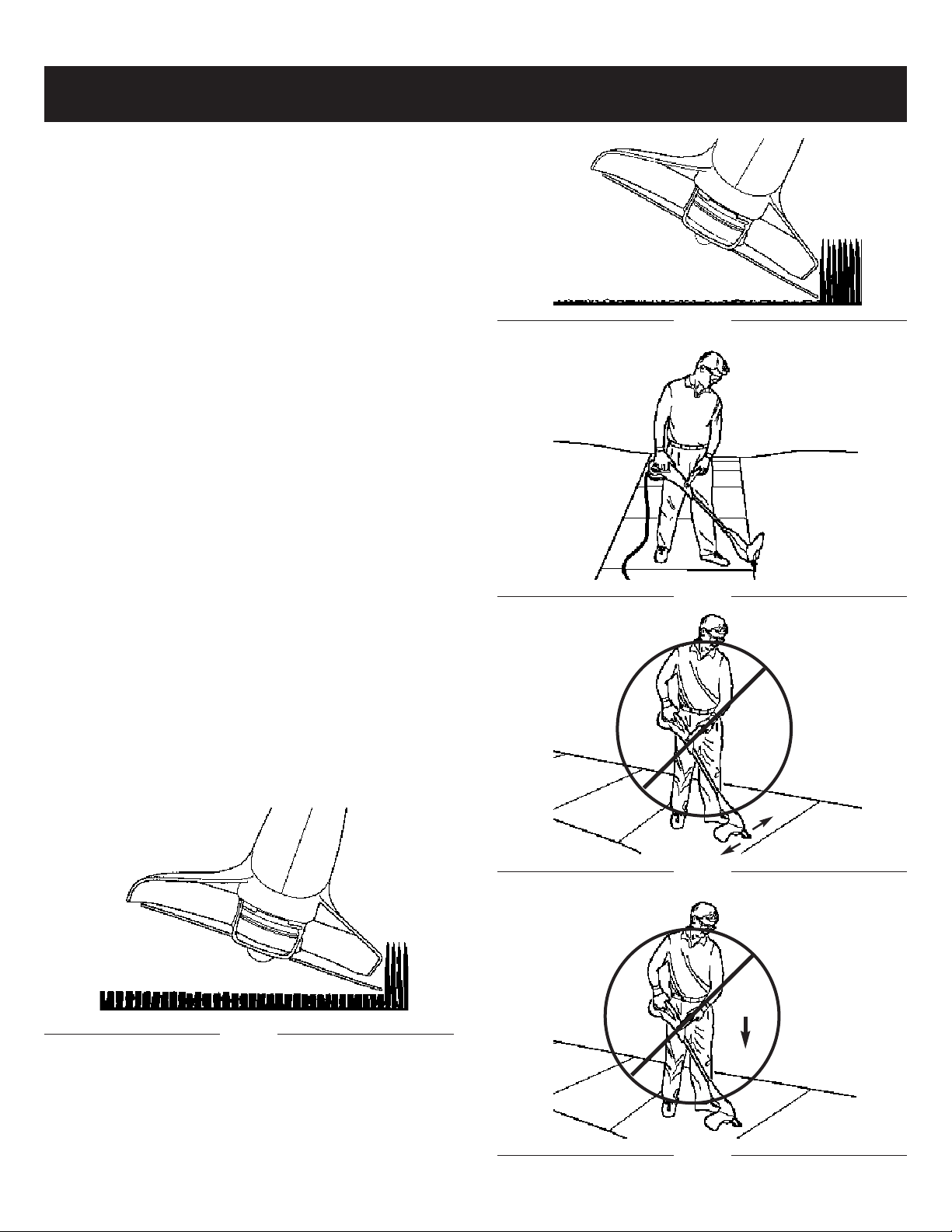
TRIMMER OPERATION
1. TRIMMING / MOWING (Fig. 12). Swing trimmer with a
sickle-like motion from side to side. Do not tilt the
stringhead during the procedure. Test area to be
trimmed for proper cutting height. Keep stringhead at
same level for even depth of cut.
Fig. 11
Fig. 12
A
10 11
OPERATING INSTRUCTIONSADJUSTMENT INSTRUCTIONS
2. CLOSER TRIMMING (Fig. 13). Position trimmer
aight ahead with a slight tilt so bottom of stringhead
str
is above ground level and string contact occurs at
proper cutting point. Always cut away from operator.
Do not pull tr
3.
FENCE/FOUNDATION TRIMMING. Approach trimming around chain link fences, picket fences, rock
walls and foundations slowly to cut close without whipping string against the barrier. If the string comes in
contact with rock, brick walls, or foundations, it will
break or fray. If string snags fencing, it will snap off.
4. TRIMMING AROUND TREES. Trim around tree
trunks with a slow approach so string does not contact
bark. Walk around the tree trimming from left to right.
Approach grass or weeds with the tip of the string and
tilt stringhead slightly forward.
SCALPING (Fig. 14). Scalping refers to removal of all
5.
vegetation down to the ground. To do this, tilt the
stringhead to about a 30 degree angle to the left. By
adjusting the handle you will have better control during this operation. Always keep a distance of 50 feet
(15 meters) from other people and animals when
scalping. Do not attempt this procedure if there is any
chance flying debris could injure operator, other people or cause damage to property.
OPERATING AS AN EDGER (Fig. 15). With the unit
6.
configured as an edger, hold it so the motor is to your
left side so that debris is thrown to the rear. Always
use eye protection.
SWEEPING - DO NOT SWEEP WITH TRIMMER (Fig.
7.
16)
8. DO NO
damage the str
immer in toward operator.
TRIMMER ON CONCRETE.
UMP
T B
inghead
(Figure 17).
This can
Fig. 14
Fig. 15
Fig. 13
Fig. 16
Fig. 17

MAINTENANCE INSTRUCTIONS
REPLACE THE SPOOL OF NYLON LINE
1. Unplug the trimmer.
2. Remove the spool assembly from the trimmer. To do
so, hold the outer ribbed part of the assembly with one
hand, while pushing down and turning the spool head
with the other to unlock it. (Fig. 18 & Fig. 19) The spool
carrier and spool will now disassemble easily.
NOTE: There is a spring inside the spool head that
could easily be lost. Insure that it is put in a safe place.
Fig. 20
A
Fig. 18
Fig. 19
3. Remove the clear plastic line retaining ring. Remove
any existing line from the spool.
Using 0.065" replacement line measure off approxi-
4.
le over the cutter line into two
Doub
mately 14' of line
.
equal lengths and place loop in slot of the spool
divider (Fig. 20).
5. Wind the line onto the spool by turning the spool. The
line should go on in the direction of the arrow (A) on
the spool (Fig. 21). Line should be wrapped tightly
around the spool. The line is wound with each half
y the divider
ated b
separ
about 6" of line left (Fig.
. Tightly wind it until there is
22).
Fig. 21
Fig. 22
12

MAINTENANCE INSTRUCTIONS
Lock the ends of the line in opposite slots on the spool
6.
(Fig. 23).Place the clear plastic line retainer back over
the line and spool (Fig. 24). Pull the lower line up into
wer slot in the clear plastic line retainer (Fig. 25).
the lo
Pull the upper line down into the upper slot (Fig. 26).
Fig. 23
Insert the line through each eyelet in the spool carrier
7.
and slide the spool into the carrier. (Fig. 27)
NOTE: Insure that the line is within the clear plastic
line retainer. If it's outside of the clear plastic line
retainer
, the line will not feed.
8. Make sure to insert the spring, assemble the spool
and spool carrier back onto the trimmer. To do so,
push the head on and turn it clockwise until it locks.
(Fig. 28 and Fig. 29)
Fig. 24
Fig. 25
Fig. 27
Fig. 28
Fig. 26
Fig. 29
13

MAINTENANCE INSTRUCTIONS
No. Parts No. Description No. Parts No. Description
1 6011-202A02 POWER CORD 28 6131-202A02 EXPANDING RING
2 6199-202A01 CORD GUARD 29 6SVABB04-10 SCREW
3 6043-202A01 PALTE (PRESSING CORD) 30 6SDABA03-16 SCREW
4 6SDABB04-14 SCREW 31 6041-840001 TERMINAL BLOCK
5 6022-202A01 SWITCH 32 6038-202A04 HOUSING (L)-MTD ROJO
6 6134-202A01 TRIGGER 33-1 6099-202B01 MOTOR
7 6024-202A01 SPRING 33-2 6187-202A01 FIX PLATE
8 6134-202A02 TRIGGER 33-3 6SADB-03-12 SCREW
9 6010-202A01 WIRE 33-4 6SADB-04-12 SCREW
10 6068-202A04 UPPER HANDGRIP (R)-MTD RED 33-5 6270-202003 WHEEL PLATE
11 6068-202A03 UPPER HANDGRIP (L)-MTD RED 34 6131-202A04 CUSHION RING
12 6056-202A03 BUTTON-Black 35 6114-202A02 EGDER GUIDE
13 6021-202A01 LEVER 36 6NBB-06 NUT
14 6024-202A02 SPRING 37 6043-815501 WASHER
15 6131-202A01 JOINT PIPE 38 6SXDB-06-20 SCREW
16 6129-202A01 CENTRAL TUBE 39 6115-202A01 SHAFT PIN
17 6SDABB04-06 SCREW 40 6137-202A01 WHEEL
18 6NGB-06 NUT 41 6NAB-05 NUT
19 6056-230302 KNOB 42 6RAE03-6.5 SCREW
20 6196-202601 ASSIST HANDLE 43 6250-202503 LINE CUTTING BLADE
21 6SHDB-06-52 SCREW 44 6262-202A02 SHIELD
22 6SDABB04-18 SCREW 45 6024-202A04 SPRING
23 6038-202A03 HOUSING (R)-MTD RED 46-1 6059-202004 BLISTER PACK
24 6059-202A01 JACKET 46-2 6008-202001A SPOOL CARRIER
25 6056-202A04 BUTTON-Black 46-3 6194-202001 TRIMMER LINE
26 6239-202A01 FIXED RING 46-4 6059-202005 SPOOL COVER
27 6024-202A03 SPIRNG 46-5 6RE-04-04 PILOT
To test if the line is advancing properly, push the but-
9.
ton with your thumb while pulling the line with your fingers. The line should advance freely. (Fig. 30).
10. In the event of the line breaking inside the spool,
repeat the replacement oper
11. Start the grass trimmer following the instructions in
the “STARTING” section.
Fig. 30
ation.
MAINTENANCE
CAUTION :
operations, cut off the electric power supply by
disconnecting the plug from the extension
cord.
1. Regular cleaning and maintenance of your string trimmer will ensure efficiency and prolong the life of your
machine.
2. After each cutting operation, take apart and clean out
the grass and soil from: the spool and its slot and in
particular the debris shield.
3. During operation, keep the air slots clean and free of
grass.
4. Only use a cloth soaked with hot water and a soft
brush to clean the string trimmer.
5. Do not spray or wet the appliance with water.
6. Do not use detergents or solvents as these could ruin
the trimmer. The parts made of plastic can easily be
damaged by chemical agents.
Before carrying out
any maintenance
Input . . . . . . . . . . . . . . . . . . . . . . . . . . . . . . . . . . . . . . . . . . . . . . . . . . . . . . . . . . . . . . . . . . . . . . . . . . . . .120V~, 60Hz, 4.5 Amp
No Load Speed . . . . . . . . . . . . . . . . . . . . . . . . . . . . . . . . . . . . . . . . . . . . . . . . . . . . . . . . . . . . . . . . . . . . . . . . . . . . . . .7,500/min
Cutting width
Line diameter
Net weight . . . . . . . . . . . . . . . . . . . . . . . . . . . . . . . . . . . . . . . . . . . . . . . . . . . . . . . . . . . . . . . . . . . . . . . . . . . . . .6.4 Lbs (2.9 Kg)
. . . . . . . . . . . . . . . . . . . . . . . . . . . . . . . . . . . . . . . . . . . . . . . . . . . . . . . . . . . . . . . . . . . . . . . . . . . . . . .15” (380mm)
. . . . . . . . . . . . . . . . . . . . . . . . . . . . . . . . . . . . . . . . . . . . . . . . . . . . . . . . . . . . . . . . . . . . . . . . . .
SPECIFICATIONS
14
ø .065”
(1.65mm)

PARTS LIST
No. Parts No. Description No. Parts No. Description
1 6011-202A02 POWER CORD 28 6131-202A02 EXPANDING RING
2 6199-202A01 CORD GUARD 29 6SVABB04-10 SCREW
3 6043-202A01 PALTE (PRESSING CORD) 30 6SDABA03-16 SCREW
4 6SDABB04-14 SCREW 31 6041-840001 TERMINAL BLOCK
5 6022-202A01 SWITCH 32 6038-202A04 HOUSING (L)-MTD ROJO
6 6134-202A01 TRIGGER 33-1 6099-202B01 MOTOR
7 6024-202A01 SPRING 33-2 6187-202A01 FIX PLATE
8 6134-202A02 TRIGGER 33-3 6SADB-03-12 SCREW
9 6010-202A01 WIRE 33-4 6SADB-04-12 SCREW
10 6068-202A04 UPPER HANDGRIP (R)-MTD RED 33-5 6270-202003 WHEEL PLATE
11 6068-202A03 UPPER HANDGRIP (L)-MTD RED 34 6131-202A04 CUSHION RING
12 6056-202A03 BUTTON-Black 35 6114-202A02 EGDER GUIDE
13 6021-202A01 LEVER 36 6NBB-06 NUT
14 6024-202A02 SPRING 37 6043-815501 WASHER
15 6131-202A01 JOINT PIPE 38 6SXDB-06-20 SCREW
16 6129-202A01 CENTRAL TUBE 39 6115-202A01 SHAFT PIN
17 6SDABB04-06 SCREW 40 6137-202A01 WHEEL
18 6NGB-06 NUT 41 6NAB-05 NUT
19 6056-230302 KNOB 42 6RAE03-6.5 SCREW
20 6196-202601 ASSIST HANDLE 43 6250-202503 LINE CUTTING BLADE
21 6SHDB-06-52 SCREW 44 6262-202A02 SHIELD
22 6SDABB04-18 SCREW 45 6024-202A04 SPRING
23 6038-202A03 HOUSING (R)-MTD RED 46-1 6059-202004 BLISTER PACK
24 6059-202A01 JACKET 46-2 6008-202001A SPOOL CARRIER
25 6056-202A04 BUTTON-Black 46-3 6194-202001 TRIMMER LINE
26 6239-202A01 FIXED RING 46-4 6059-202005 SPOOL COVER
27 6024-202A03 SPIRNG 46-5 6RE-04-04 PILOT
15

MANUFACTURER’S LIMITED WARRANTY FOR:
The limited warranty set forth below is given by Troy-Bilt LLC
with respect to new merchandise purchased and used in the
United States, its possessions and territories.
Troy-Bilt LLC warrants this product against defects in material and workmanship for a period of two (2) years commencing
on the date of original purchase and will, at its option, repair or
replace, free of charge, any part found to be defective in material or workmanship. This limited warranty shall only apply if
this product has been operated and maintained in accordance
with the Operator’s Manual furnished with the product, and
has not been subject to misuse, abuse, commercial use, neglect, accident, improper maintenance, alteration, vandalism,
theft, fire, water or damage because of other peril or natural
disaster. Damage resulting from the installation or use of any
accessory or attachment not approved by Troy-Bilt LLC for
use with the product(s) covered by this manual will void your
warranty as to any resulting damage. This warranty is limited
to ninety (90) days from the date of original retail purchase for
any Troy-Bilt product that is used for rental or commercial purposes, or any other income-producing purpose.
HOW TO OBTAIN SERVICE: Warranty service is available,
WITH PROOF OF PURCHASE THROUGH YOUR LOCAL
AUTHORIZED SERVICE DEALER. To locate
area, visit our website at www.troybilt.com,
the Yellow Pages, call 1-800-520-5520 or write to
361131, Cleveland, OH 44136-0019
This limited warranty does not provide coverage in the
following cases:
A. Trimmer line.
B. Troy-Bilt LLC does not extend any warranty for prod-
ucts sold or exported outside of the United States of
America, its possessions and territories, except those
sold through Troy-Bilt’s authorized channels of export
distribution.
eserves the right to change or improve the
oy-Bilt LLC
r
T
design of any Troy-Bilt Product without assuming any obligation to modify any product previously manufactured.
r
.
the dealer in your
check for a listing in
P.O. Box
No implied warranty, including any implied warranty of
merchantability or fitness for a particular purpose,
applies after the applicable period of express written warranty above as to the parts as identified. No other express
warranty or guaranty, whether written or oral, except as
mentioned above, given by any person or entity, including
a dealer or retailer, with respect to any product shall bind
Troy-Bilt LLC During the period of the Warranty, the
exclusive remedy is repair or replacement of the product
as set forth above.
how long an implied warranty lasts, so the above limitation
may not apply to you.)
The provisions as set forth in this Warranty provide the
sole and exclusive remedy arising from the sales. TroyBilt LLC shall not be liable for incidental or consequential
loss or damages including, without limitation, expenses
incurred for substitute or replacement lawn care services, for transportation or for related expenses, or for rental
expenses to temporarily replace a warranted product.
(Some states do not allow limitations on how long an implied
warranty lasts, so the above limitation may not apply to you.)
In no event shall recovery of any kind be greater than the
amount of the purchase price of the product sold. Alteration
of the safety features of the product shall void this Warranty.
You assume the risk and liability for loss, damage, or injury to
you and your property and/or to others and their property
arising out of the use or misuse or inability to use the product.
This limited warranty shall not extend to anyone other than
the original purchaser, original lessee or the person for whom
it was purchased as a gift.
How State Law Relates to this Warranty: This warranty
gives you specific legal rights, and you may also have other
rights which vary from state to state.
o locate your near
T
(Some states do not allow limitations on
vice dealer dial
est ser
1-800-520-5520.
16
Troy-Bilt LLC
P.O. Box 361131
Cleveland, OH 44136-0019

Manuel del Dueño/Operador
Recortador/Cortador
de Cesped Eléctrico
Modelo TB45E
PRECAUCIÓN: Antes de utilizar este
producto, lea este manual y siga todas
las reglas de seguridad e instrucciones de funcionamiento.
P/N 6096-202B02
PRINTED IN CHINA
• SEGURIDAD
• ENSAMBLAJE
• FUNCIONAMIENTO
• MANTENIMIENTO
• LISTA DE COMPONENTES

ÍNDICE
Garantía Página 18
Reglas de seguridad Página 19 - 23
Ensamblaje Página 24
Instrucciones de Ajuste Página 25 - 26
Instrucciones de Operación Página 26 - 27
Mantenimiento Página 28 - 30
Especificaciones Página 30
Lista de piezas Página 31
DECLARACIÓN DE GARANTÍA
GARANTÍA LIMITADA DE DOS AÑOS EN LA BORDEADORA DE CÉSPED TROY BILT
Troy Bilt reparará cualquier defecto material o de fabricación de forma gratuita durante un plazo de
dos años desde la fecha de compra, siempre y cuando la bordeadora haya sido usada y mantenida de
acuerdo con el manual de usuario.
Si esta Bordeadora de césped se usa comercialmente o para alquiler, esta garantía estará en vigor
durante sólo 90 días desde la fecha de compra.
EL SERVICIO DE GARANTÍA ESTÁ DISPONIBLE DEVOLVIENDO ESTA BORDEADORA DE
CÉSPED AL CENTRO DE SERVICIO TROY BILT MÁS CERCANO EN LOS ESTADOS UNIDOS.
LLAME AL 1-800-520-5520 PARA RECIBIR INFORMACIÓN SOBRE DIRECCIONES.
Esta garantía le da derechos legales específicos. Puede tener otros derechos, que varían de estado a
estado.
18

REGLAS DE FUNCIONAMIENTO SEGURO
El propósito de los símbolos de seguridad es atraer su
atención sobre posibles peligros. Los símbolos de
seguridad y su explicación merecen su atención y
comprensión. Las advertencias de seguridad no eliminan el peligr
advertencias que ofrecen no son sustitutas de ninguna
medida de prevención de accidentes.
SÍMBOLO SIGNIFICADO
o por sí mismas. Las instrucciones o
ALERTA DE SEGURIDAD:
Indica peligro, advertencia o precaución. Se
requiere atención para evitar daños personales. Puede utilizarse con otros símbolos o
pictogramas.
NOTA: Le avisa de información o instrucciones vitales para
el funcionamiento del equipo.
Lea el Manual del Usuario y siga todas las advertencias e instrucciones de seguridad.
Si no lo hace pueden producirse daños en el operador y los que le rodean.
SÍMBOLO
SIGNIFICADO
PELIGRO:
Si no se obedece una
advertencia pueden producirse daños personajes a usted o a terceros. Siga siempre las precauciones de
seguridad para reducir el riesgo de incendio
o daños personales.
ADVERTENCIA:
Si no se obe-
dece una
advertencia pueden producirse daños en
usted o en otros. Siga siempre las instrucciones de seguridad para reducir el riesgo
de incendio y daños personales.
PRECAUCIÓN:
Si no obedece
un aviso puede
resultar dañada su propiedad o usted
mismo. Siga siempre las precauciones para
reducir el riesgo de incendio y daños personales.
• INSTRUCCIONES IMPORTANTES DE SEGURIDAD •
LEA TODAS LAS INSTRUCCIONES DE
ANTEMANO
• Lea las instrucciones detenidamente. Familiarícese con
los controles y el uso adecuado de la unidad.
ADVERTENCIA:
seguir las nor
ciones antes de manipular la unidad para asegurar
la seguridad del operador y de aquellos que lo
odean. Conser
r
o.
futur
•
No opere esta unidad si está cansado, enfermo o bajo la
influencia del alcohol, drogas o medicamentos.
Los niños no debe operar la unidad. Los adolescentes
•
deben encontrarse acompañados por un adulto.
• Todos los dispositivos de seguridad deben encontrarse
instalados y en buen estado de funcionamiento antes de
manipular la unidad.
Inspeccione la unidad antes de utilizarla. Reemplace
•
todos los componentes dañados antes de comenzar a
usarla. Asegúr
mente antes de ar
que estén rotos o dañados de cualquier forma. No
manipule la unidad se tiene componentes sueltos o
dañados.
mas de seguridad. Lea estas instr
ve estas instr
ese de que la unidad funciona correcta-
rancarla. Reemplace los componentes
Al utilizar la
unidad, debe
uc
ucciones para uso
-
• Inspeccione la zona detenidamente antes de arrancar la
unidad. Retire cualquier deshecho u objetos duros o
blandos como puedan ser cristales, cables, etc.
• Mantenga alejados de la zona a niños, personas o mascotas. Como mínimo, mantenga a todos los niños y mascotas a una distancia de 50 pies (15 m.); aún así puede
existir riesgo para los observadores causados por objetos lanzados por la máquina. Se recomienda a los observadores que utilicen gafas protectoras. Si alguien se le
apr
oxima, detenga la unidad inmediatamente.
19

RECOMENDACIONES P
ARA EL CALIBRE
MINIMO DEL ALAMBRE
VOLTIOS
LONGITUD DE
CABLE DE
EXTENSION
T
AMAÑO
REQUERIDO DEL
ALAMBRE
120
25 pies / 7.5m 18 A.W.G.*
50 pies / 15m 16 A.W.G.*
100 pies / 30m 16 A.W.G.*
*Calibre para Alambre de los E.U.A.
REGLAS DE FUNCIONAMIENTO SEGURO REGLAS DE FUNCIONAMIENTO SEGURO
FAVOR DE LEER - CONSERVE
ESTAS INSTRUCCIONES
Al utilizar un apar
precauciones básicas para asegurar una protección máxima y un rendimiento óptimo. Lea este manual antes de
ensamblar y operar este aparato. Si no sigue las instrucciones podría provocar el riesgo de incendio, choque eléctrico o heridas personales.
ato eléctrico siempre debe seguir ciertas
ADVERTENCIA
PARA REDUCIR EL RIESGO DE CHOQUEN
ELECTRICO, INCENDIO O HERIDAS PERSONALES:
1. SIGA TODAS LAS INSTRUCCIONES DE SEGURI-
enlistadas en este manual antes y durante la
DAD
operación de esta recortadora.
2. PARA REDUCIR EL RIESGO DE CHOQUE ELEC-
TRICO, este equipo cuenta con un enchufe polarizado (una clavija es más ancha que la otra). Este
enchufe embonará en una toma de corriente polarizada de una sola manera. Si el enchufe no embona por
completo, inviértalo. De ninguna manera intente cambiar el enchufe.
3. REVISE LA UNIDAD POR SI HAY DAÑOS en el
bastidor, el cable o el enchufe. Mantenga todos los
sujetadores apretados. No la use si el interruptor no
apaga su unidad adecuadamente. Nunca la opere si
el cable o el enchufe han sido dañados, si el motor no
funciona como debería, o si la unidad ha sido golpeada, dañada o dejada caer en agua. Nunca la haga
funcionar con alguna apertura de aire bloqueada.
Conserve todas las aperturas libres de desechos que
puedan reducir el flujo de aire. Reemplace las partes
dañadas que estén astilladas, cuarteadas o en mal
estado, de manera que puedan volar y causar alguna
herida seria. Mantenga cuchillo de cortador agudo.
4.
5.
DOBLE AISLAMIENTO para ayudar a prote-
.
lo contr
ger
ción de dob
a los choques eléctr
le aislamiento consiste en 2
icos
“capas”
radas de aislamiento eléctrico. Los aparatos construidos con este sistema de aislamiento no están diseña
Como resultado de esto
dos par
a conectarse a tierr
a.
el cable de extensión utilizado con este aparato
puede conectarse en cualquier toma eléctrica convencional de 120 voltios. Deben observarse las precauciones normales de seguridad al operar un apara-
El sistema de dob
.
to eléctr
par
ico
a aumentar la protección contr
le aislamiento sólo es
a her
pudieran resultar por una posible falla de aislamiento
eléctrico interno.
CABLE DE EXTENSION - Uselo e
un cable de extensión diseñado para exteriores. Vea
xclusiv
La construc-
sepa
idas que
amente con
la tabla de abajo. Puede usar un cable de dos alambres sin una conexión a tierra ya que este aparato
está doblemente aislado. En caso existir duda sobre
la medida adecuada del alambre, use el calibre que le
sigue para un mayor grosor. Observe que entre más
pequeño es el número de calibre, más grueso es el
cable.
Tabla 1
(1). Al utilizar este aparato, debe usar un cable de exten-
sión del tamaño adecuado por seguridad y para evitar
una pérdida de potencia o sobrecalentamiento.
(2). El cable de extensión debe estar diseñado específica-
mente para uso en exteriores y marcado con “SJ” o
“SJT” y con el sufijo “WA”. En Canadá, el cable de
extensión debe estar marcado con “SFTW”.
(3). Revise la extensión del cable de energía por si hay
alambres sueltos o expuestos, o por si el aislamiento
está dañado. En caso de que sea así, reemplácelo
antes de utilizar el aparato.
NO MALTRATE EL CABLE – Nunca jale el cable
para transportar el aparato o para desonectarlo de la
toma de corriente. Mantenga el cable a distancia del
operador y de cualquier obstáculo en todo momento.
No explonga el cable a superficies caliente, aceite o
agua. No jale el cable alrededor de borde u orillas
filosas ni cierre puertas sobre éste.
6.
NO INCLUYE PARTES DE REPUESTO – Su
aparato doblemente aislado no cuenta con
partes de repuesto en su interior. No intente hacer
reparaciones usted mismo. Para información sobre el
servicio, consulte al Departamento de Servicios para
-
Productos Troy Bilt enlistado en el reverso de Manual
del Usuario.
,
7. RIESGO DE HERIDAS EN LOS OJOS – Siempre
use lentes protectores cuando opere su recortadora.
El desorillar aumenta el riesgo de heridas causadas
por desechos que vuelan. Mantenga siempre a los
espectaroes a una distancia segura.
8. CONSERVE LAS MANOS Y LOS PIES ALEJADOS
de la línea giratoria. No opere sin la protección instalada.
9. VISTA ADECUADAMENTE – Use siempre pan-
talones largos, zapatos y guantes. No opere sin el
protector para residuos instalado.
20

10. MANTENGA EL ÁREA LIBRE DE OBSTÁCULOS -
Mantenga a todo el mundo, especialmente niños y
mascotas
pies (15 m). Apague el aparato inmediatamente si
alguien le acerca. Nunca permita a los niños usar el
aparato, usarlo como un juguete o usarlo sin supervisión.
11. EVITE UN AMBIENTE PELIGROSO – No lo use en
presencia de líquidos o gases inflamables, materiales
humeantes o ardientes, para evitar que produzca un
incendio o alguna explosión. Nunca opere su recortadora en condiciones húmedas o mojadas, alrededor
de albercas, etc. No lo use bajo la lluvia. No agarre el
enchufe, el cable o el aparato con las manos
mojadas.
12.
USE EL AP
exclusivamente para lo que fue hecho y como se
describe en este manual. NO BARRA CON LA
RECORTADORA - El barrer significa ladear la cabeza
de hilo con el fin de quitar desechos de las banquetas, etc. Su recortadora es una potente herramienta y
pequeñas piedras u otros escombros similares peuden ser lanzados 50 pies o más, causando heridas o
daños a propiedades cercanas tales como
automóviles, casas y ventanas. Inspeccione el área
antes de encender el aparato para remover desechos
y otros objetos que pueden causar daños durante la
operación.
NO USE ACCESORIOS o aditamentos con excep-
13.
ción de los recomendados y suministrados por Troy
Bilt, No use ningún tipo de línea cortadora metálica o
alámbrica.
14. NO SE EXTRALIMITE – Conser
equilibrio firme en todo momento.
15. EVITE UN ENCENDIDO INVOLUNTARIO – No trans-
por
interruptor.
16. DESCONECTE la recortadora de la corriente eléctrica cuando no la use o antes de realizar el servicio de
la cabeza de hilo.
ALMACENE la recortadora inactiva en el interior.Este
17.
apar
y seguros - fuera del alcance de los niños.
18. No toque las cuchillas de corte expustas ni los bordes
de corte cuando tome o levente el aparato.
19. NO FUERCE EL AP
jo y con menos probabiliada de un riesgo de lesión a
la velocidad para la cual se diseñó.
, alejados de la zona de operación unos 50
ARATO CORRECTO
te la recortadora conectada con el dedo en el
ato debe ser almacenado en lugares secos
O
T
ARA
– Use este apar
e una posición y
v
- realizará mejor el tr
ato
, altos
aba
EXPLICACION DE NOTA, ADVERTENCIA Y
SIMBOLO DE GARANTIA
Una NOTA
1.
cional, para destacar una explicación particular, o
para expander una instrucción específica.
2. Una
3. EL (
4. 4.
ADVERTENCIA identifica un procedimiento que,
si no se acomete o se realiza inadecuadamente,
puede provocar heridas personales y/o daños a la
unidad.
ficar que por los menos las instrucciones o
procedimientos deben llevarse al cabo, cualiquier
daño invalidará la garantía y los gastos de la reparaciones serán asumidos por el dueño
servicio, con excepción del mantenimiento del
usuario, deberá ser realizado por un Centro de
Servicio Autorizado Troy Bilt. Los daños o condiciones
causadas por practicas de mantenimiento inadecuadas, las cuales hagan que el producto sea inoperable invalidarán la garantía del fabricante.
PARA LA GARANTIA O EL SERVICIO póngase
en contacto con el Centro de Servicio Autorizado de
Troy Bilt llamando al número 800# de la cubierta posterior.
usada par
SIMBOLO DE GARANTIA) sirve para noti-
a comunicar información adi-
. Cualquier otro
CONSERVE ESTAS
INSTRUCCIONES
-
21

REGLAS DE FUNCIONAMIENTO SEGURO
SEGURIDAD Y SÍMBOLOS INTERNACIONALES
Este manual del usuario describe los símbolos de seguridad internacionales que pueden aparecer en este producto. Lea el
manual del usuario para obtener infor
mación sobre seguridad, ensamblaje, funcionamiento y mantenimiento.
SÍMBOLO SINGIFICADO
• SÍMBOLO ALERTA DE SEGURIDAD
Indica peligro, advertencia o precaución. Puede utilizarse en conjunto
con otros símbolos o pictogramas.
• LEA EL MANUAL DEL USUARIO
ADVERTENCIA: Lea
el Manual del Usuario y siga las
advertencias e instrucciones. Si no lo
hace puede provocar serios daños al
operador o los que lo rodean.
• UTILICE PROTECCIÓN PARA
OJOS, OÍDOS Y CABEZA
ADVERTENCIA: Los
objetos lanzados y los ruidos
potentes pueden dañar los ojos y el
oído. Utilice protección ocular según
la norma ANSI Z87.1-1989 y protección auditiva al utilizar esta unidad.
Utilice casco. Utilice una mascara si
es necesario
SÍMBOLO SINGIFICADO
• DISTANCIA MÍNIMA OPERATIVA
ADVERTENCIA:
Mantenga a niños, observadores y
animales a 50 pies (15 m.). Si se
aproxima alguien, detenga la unidad
inmediatamente.
PELIGRO: La máquina
puede lanzar objetos.
22

REGLAS DE FUNCIONAMIENTO SEGURO
CONOZCA SU BORDEADORA DE CÉSPED
INTERRUPTOR DE SEGURIDAD
GATILLO DE
ENCENDIDO/APAGADO
MANUBRIO AUXILIAR
MANUBRIO TRASERO
CABLE ELÉCTRICO
RETENEDOR DEL CABLE
RUEDA
DE
DE EXTREMO
BOTÓN DE AJUSTE
CUCHILLA
GUÍA
BOTÓN DE CONVERIÓN
DE EJES
FLECHA AJUSTABLE
DE
APERTURAS DE AIRE
PROTECTOR
DESECHOS
CABEZA DE HILO
TUERCA
23
MARIPOSA DEGUÍA
DE
DE EXTREMO

INSTRUCCIONES DE ENSEMBLADO
NOTA: El único montaje necesario para la recortadora es
instalar la rueda de guía del extremo, la protección contra
residuos y el mango de asistencia.
INSTALACIÓN DE LA RUEDA DE GUÍA DEL
EXTREMO
1. Coloque la rueda guía de reborde (A) al frente de la
carcasa del motor como e muestra en la Fig. 1.
2. Apriete la tuerca de mariposa (B) firmemente. (Fig. 2)
A
Fig. 1
Fig. 3
C
C
B
Fig. 2
INSTALACIÓN DE LA PROTECCIÓN CONTRA
RESIDUOS
1. Coloque el compartimento del motor con el portador
(Fig. 3)
del cabezal de cuerda mir
2. Deslice la protección contra residuos sobre el compartimento del motor.
iétela con 4 tornillos (C). (Fig. 4)
Apr
3.
ando hacia arr
iba.
Fig. 4
24

INSTRUCCIONES DE AJUSTE
AJUSTE LA LONGITUD DEL EJE
1. Agarre el eje firmemente.
2. Presione el botón rojo para liberar el eje hacia adelante y mueva el manubrio hacia atrás a la longitud
deseada (Figura 5).
NOTA: El eje puede ser ajustado ya sea en modo de recortadora o de desorilladora.
A
Fig. 5
TRANSFORMACION A DESORILLADORA
1. Agarre el eje firmemente.
2. Pulse el botón de extremo (B) y gire el montaje del
mango hasta que se oiga un clic. (Fig 6 y Fig. 7)
3. Ajuste el mango de asistencia según lo necesite.
AJUSTE DE EL MENUBRIO AUXILIAR
TA:
NO
sido girada hacia abajo para empacarse.
1. Afloje la perilla de ajuste y gire la manija hacia arriba
2. Reapriete la perilla de ajuste seguramente.
La manija de a
del mango (Figura 8).
yuda está atada al mango pero ha
Fig. 8
ENCENDIDO
1. Antes de encender la bordeadora de césped por
primera vez, asegúrese de que las líneas de nylon
toquen o pasen por encima de la cuchilla de cortar las
líneas. Si no son lo suficientemente largas, pulse la
perilla de choque y, a la vez, tire de las líneas de
nylon. (Fig. 9).
B
Fig. 6
Fig. 7
Fig. 9
2. Conecte el alargador correcto al cable de ali-
a según las instrucciones
mentación de la recor
de la sección Conectar el cable.
3. Asegúrese de que la longitud de la recortadora de
hierba y la posición del mango de asistencia es la
eniente antes de su utilización, ajuste la longitud
v
con
del recor
del eje, ajuste la altura del mango de asistencia
soltando el botón de ajuste.
25
tador de hierba pulsando el botón de ajuste
tador

INSTRUCCIONES DE AJUSTE
Sostenga firmemente la cortadora de césped y, sin
4.
dejarla tocar el césped que va a cortar, hale el interruptor de seguridad, luego presione el gatillo del
mango superior. Deje que la cortadora de cordel
opere por unos pocos segundos y "choque" el
cabezote de cordel contra el césped. El cordel de
Nylon se liberará automáticamente. La cuchilla de
corte en la guarda escombros cortará el exceso de
cordel.
5. Para apagar la unidad simplemente deje de presionar
el interruptor de encendido.
PRECAUCIÓN :
tada realiza un corte menos eficiente. Para
mejorar su rendimiento en futuros usos, golpee
el botón de la bobina (A) con suavidad en el
suelo mientras la bordeadora esté funcionando.(Fig. 10)
Una línea
corta o gas-
INSTRUCCIONES DE OPERACION
Esta oper
ciar el trabajo con el fin de asegurarse que todo esta funcionando correctamente y para que usted se familiarice
con el orillador de pasto. Inicie lentamente , cuando
obtenga experiencia podrá usar su orillador de pasto a su
máxima capacidad.
ación debe repetirse algunas veces antes de ini-
A
Fig. 10
CONECTE EL CABLE
1. Asegúrese de que el cable NO esté conectado en el
receptáculo antes de este procedimiento.
2. Haga una lazada con 20-25cm (8-10
del cable extensión.
3. Coloque el bucle en la ranura (A) debajo de la manija
posterior y asegúrelo en su sitio en el retén de cordel
como se muestra en la Figura 11.
4. Conecte el cable de extensión al de la recortadora.
5. Enchufe el cable de extensión en el receptáculo
SOLO cuando esté preparado para hacer funcionar la
tadora.
recor
″) del extremo
A
OPERACIÓN DEL CORTADOR ORILLADOR
1. CORTADOR DE PASTO (Fig. 12). Columpie la unidad
de lado a lado. No incline el cabezal en este
movimiento. Haga una prueba para definir la altura de
corte. Mantenga el cabezal a una misma altura para
un corte parejo.
Fig. 12
Fig. 11
26

INSTRUCCIONES DE OPERACION
2. CORTE MAS CERCANO (Fig. 13). Posicione el
cabezal un poco inclinado , siempre cor
personas y del operador.
3.
TE EN ORILLAS.
COR
Acerque el cabezal a las or
las que desea cortar, inicie el proceso de corte acercando poco a poco a el objeto conde quiere cortar las
orillas de pasto , corte pero no acerque tanto que
toque el objeto ya que el hilo se romperá.
4.
ORILLAR ALREDEDOR DE ARBOLES. Corte
alrededor de arboles sin tocar la corteza del árbol,
utilice la guÌa de corte para que por ningún motivo
toque el árbol, puede dañar al árbol si le llega a cortar la corteza del mismo.
REMOVER VEGETACIÓN (Fig. 14). Gire la unidad 30
5.
grados hacia la izquierda. Ajustando el maneral tendrá mejor control de esta operación. Siempre mantenga una distancia de 50 pies (15 metros) de cualquier
persona o animal . No intente hacer esta operación si
existe la posibilidad de que alguna partÌcula pudiera
dañar al operador, a otras personas o pueda dañar
objetos .
OPERACIÓN COMO ORILLADOR (Fig. 15. Con la
6.
unidad configurada como orillador, sujétela con el
motor a la izquierda, de tal forma que las partÌculas
sean lanzadas hacia atrás. Siempre utilice protector
para los ojos.
BARREDOR - NUNCA UTILICE SU UNIDAD PARA
7.
ESTE TRABAJO (Fig. 16)
NO HAGA FUNCIONAR EL RECORTADOR SOBRE
8.
HORMIGÓN. Esto podría dañar el cabezal de cuerdas (Figura 17).
te alejado de
il-
Fig. 14
Fig. 15
Fig. 13
Fig. 16
Fig. 17
27

INSTRUCCIONES DE MAINTENIMIENTO
SUSTITUCIÓN DEL CARRETE DEL CABLE DE
NYLON
1. Desconecte la recortadora.
2. Retire el conjunto del rotor de la podadora. Para hac-
lo, sostenga la parte acanalada exterior del conjun-
er
to con una mano, mientras empuja hacia abajo y gira
la cabeza del rotor con la otra mano para separarla
(Fig. 18 & Fig. 19). El portador del rotor y el rotor
ahora se separarán fácilmente.
NOTA: Hay un resorte dentro de la cabeza del rotor
que se podría perder fácilmente. Asegúrese de colocarlo en un lugar seguro.
Fig. 20
A
Fig. 18
Fig. 19
Retire el anillo de retencion de plastico tr
3.
Retire cualquier linea existente del rotor.
4. Usando la linea de reemplazo 0.065”, mida aproximadamente 14’
tador en dos longitudes iguales y coloque el rotor en
la ranura del divisor del rotor (Fig. 20)
Enrolle la línea en el rotor gir
5.
debe ir en la dirección de la flecha (A) en el rotor (Fig.
21) La línea se debe enrollar fuer
La línea se enrolla con cada mitad separ
del rotor
por el divisor. Enrolle fuertemente hasta que queden
aproximadamente 6” de línea (Fig. 22)
.
de línea. Doble sobre la línea del cor-
ando el mismo
temente alrededor
ansparente
La línea
.
ada
Fig. 21
Fig. 22
.
28

INSTRUCCIONES DE MAINTENIMIENTO
Ajuste los extremos de la línea en las ranuras opues-
6.
tas en el rotor (Fig. 23) Coloque el retenedor de línea
de plástico transparente de nuevo sobre la línea y el
rotor (Fig.
el retenedor de la línea de plástico transparente (Fig.
25) Jala la línea superior hacia la ranura superior (Fig.
26).
24) Jale la linea hasta la ranura inferior en
Fig. 23
Inserte la línea a través de cara ojal en el portador del
7.
rotor y deslice el rotor en el portador. (Fig. 27)
NOTA: Asegúrese que la línea está dentro del retenedor de plástico tr
ansparente. Si está fuera del retene-
dor de plástico transparente, la línea no avanzara.
8. Asegúrese de insertar el resorte, ensamblar el rotor y
el portador de rotor de nuevo en la podadora. Para
hacerlo, empuje la cabeza y gírela hacia la derecha
hasta que embone. (Fig. 28 y Fig. 29)
Fig. 27
Fig. 24
Fig. 25
Fig. 26
Fig. 28
Fig. 29
29

INSTRUCCIONES DE MAINTENIMIENTO
No. Pieza No. Descripción No. Pieza No. Descripción
1 6011-202A02 CABLE DE ALIMENTACIÓN 28 6131-202A02 ANILLO DE XPANSIÓN
2 6199-202A01 PROTECCIÓN DE CABLE 29 6SVABB04-10 TORNILLO
3 6043-202A01 CUBIERTA (PRESIONA CABLE) 30 6SDABA03-16 TORNILLO
4 6SDABB04-14 TORNILLO 31 6041-840001 ABRAZADERA DE TORNILLO
5 6022-202A01 INTERRUPTOR 32 6038-202A04 CARCASA (I)-MTD ROJO
6 6134-202A01 GATILLO 33-1 6099-202B01 MOTOR
7 6024-202A01 MUELLE 33-2 6187-202A01 PLACA DE FIJACIÓN
8 6134-202A02 GATILLO 33-3 6SADB-03-12 TORNILLO
9 6010-202A01 ALAMBRE 33-4 6SADB-04-12 TORNILLO
10 6068-202A04 MANILLAR SUPERIOR (D)-MTDROJO 33-5 6270-202003 PLACA DE RUEDA
11 6068-202A03 MANILLAR SUPERIOR (I)-MTD ROJO 34 6131-202A04 ANILLO AMORTIGUADOR
12 6056-202A03 BOTÓN- Negro 35 6114-202A02 GUÍA DE LA CUCHILLA
13 6021-202A01 PALANCA 36 6NBB-06 TUERCA
14 6024-202A02 MUELLE 37 6043-815501 ARANDELA
15 6131-202A01 TUBO DE UNIÓN 38 6SXDB-06-20 TORNILLO
16 6129-202A01 TUBO CENTRAL 39 6115-202A01 CLAVIJA DEL EJE
17 6SDABB04-06 TORNILLO 40 6137-202A01 RUEDA
18 6NGB-06 TUERCA 41 6NAB-05 TUERCA
19 6056-230302 PERILLA 42 6RAE03-6.5 TORNILLO
20 6196-202601 PALANCA AUXILIAR 43 6250-202503 HOJA DE CORTE LINEAL
21 6SHDB-06-52 TORNILLO 44 6262-202A02 BLINDAJE
22 6SDABB04-18 TORNILLO 45 6024-202A04 MUELLE
23 6038-202A03 CARCASA (D)-MTD ROJO 46-1 6059-202004 BLÍSTER
24 6059-202A01 JACKET 46-2 6008-202001A PORTABOBINAS
25 6056-202A04 BOTÓN-Negro 46-3 6194-202001 LÍNEA DE CORTE
26 6239-202A01 ANILLO FIJO 46-4 6059-202005 TAPA DE LA BOBINA
27 6024-202A03 MUELLE 46-5 6RE-04-04 PILOTO
Para probar si la línea está avanzando adecuada-
9.
mente, presione el botón con su pulgar mientras jala
la línea con sus dedos. La línea deberá avanzar libre-
. (Fig. 30)
mente
10. En caso de que la línea se rompa dentro del rotor,
repita la operación de reemplazo.
11. Encienda el podador de pasto siguiente las instrucciónes en la seccion de “ARRANQUE”.
Fig. 30
MAINTENIMIENTO
PRECAUCION :
cualquier procedimiento de mantenimiento de
su unidad, corte completamente el suministro
de corriente eléctrica de la unidad
desconectando la clavija de la extensión eléctrica.
1. Un regular mantenimiento y aseo de su maquina asegurara un funcionamiento mas eficiente y prolongara
la vida de su unidad.
2. Después de cada operación de corte, limpie y quite la
tierra y pasto de el cabezal y particularmente de la
guarda.
3. Mientras opera la unidad asegúrese de que las
ranuras d ventilación están limpias y libres de tierra y
pasto.
4. Unicamente utilice un trapo húmedo con agua
caliente y un cepillo delgado para limpiar su maquina.
5. No rocÌe o moje su unidad con agua.
6. No utilice detergentes o solventes ya que esto pudiera
arruinar su unidad.
7. Si la línea de corte ya no corta o se rompe, reemplácela contactando un centro de servicio autorizado.
Antes de
practicar
Potencia . . . . . . . . . . . . . . . . . . . . . . . . . . . . . . . . . . . . . . . . . . . . . . . . . . . . . . . . . . . . . . . . . . . . . . . . . . . . .120V~, 60Hz, 4,5A
Velocidad no Instalada . . . . . . . . . . . . . . . . . . . . . . . . . . . . . . . . . . . . . . . . . . . . . . . . . . . . . . . . . . . . . . . . . . . .7,500 min
Diámetro del Círculo de Cor
Reser
Peso neto . . . . . . . . . . . . . . . . . . . . . . . . . . . . . . . . . . . . . . . . . . . . . . . . . . . . . . . . . . . . . . . . . . . . . . . . . . . . .6,4 Lbs (2,9 Kg )
a del la línea
v
. . . . . . . . . . . . . . . . . . . . . . . . . . . . . . . . . . . . . . . . . . . . . . . . . . . . . . . . . . . . . . . . . . . . .
te . . . . . . . . . . . . . . . . . . . . . . . . . . . . . . . . . . . . . . . . . . . . . . . . . . . . . . . . . . . . . . . . .15” (380mm)
ESPECIFICACIONES
30
ø .065”
-1
/RPM
(1.65mm)

LISTA DE PIEZAS
No. Pieza No. Descripción No. Pieza No. Descripción
1 6011-202A02 CABLE DE ALIMENTACIÓN 28 6131-202A02 ANILLO DE XPANSIÓN
2 6199-202A01 PROTECCIÓN DE CABLE 29 6SVABB04-10 TORNILLO
3 6043-202A01 CUBIERTA (PRESIONA CABLE) 30 6SDABA03-16 TORNILLO
4 6SDABB04-14 TORNILLO 31 6041-840001 ABRAZADERA DE TORNILLO
5 6022-202A01 INTERRUPTOR 32 6038-202A04 CARCASA (I)-MTD ROJO
6 6134-202A01 GATILLO 33-1 6099-202B01 MOTOR
7 6024-202A01 MUELLE 33-2 6187-202A01 PLACA DE FIJACIÓN
8 6134-202A02 GATILLO 33-3 6SADB-03-12 TORNILLO
9 6010-202A01 ALAMBRE 33-4 6SADB-04-12 TORNILLO
10 6068-202A04 MANILLAR SUPERIOR (D)-MTDROJO 33-5 6270-202003 PLACA DE RUEDA
11 6068-202A03 MANILLAR SUPERIOR (I)-MTD ROJO 34 6131-202A04 ANILLO AMORTIGUADOR
12 6056-202A03 BOTÓN- Negro 35 6114-202A02 GUÍA DE LA CUCHILLA
13 6021-202A01 PALANCA 36 6NBB-06 TUERCA
14 6024-202A02 MUELLE 37 6043-815501 ARANDELA
15 6131-202A01 TUBO DE UNIÓN 38 6SXDB-06-20 TORNILLO
16 6129-202A01 TUBO CENTRAL 39 6115-202A01 CLAVIJA DEL EJE
17 6SDABB04-06 TORNILLO 40 6137-202A01 RUEDA
18 6NGB-06 TUERCA 41 6NAB-05 TUERCA
19 6056-230302 PERILLA 42 6RAE03-6.5 TORNILLO
20 6196-202601 PALANCA AUXILIAR 43 6250-202503 HOJA DE CORTE LINEAL
21 6SHDB-06-52 TORNILLO 44 6262-202A02 BLINDAJE
22 6SDABB04-18 TORNILLO 45 6024-202A04 MUELLE
23 6038-202A03 CARCASA (D)-MTD ROJO 46-1 6059-202004 BLÍSTER
24 6059-202A01 JACKET 46-2 6008-202001A PORTABOBINAS
25 6056-202A04 BOTÓN-Negro 46-3 6194-202001 LÍNEA DE CORTE
26 6239-202A01 ANILLO FIJO 46-4 6059-202005 TAPA DE LA BOBINA
27 6024-202A03 MUELLE 46-5 6RE-04-04 PILOTO
31

GARANTÍA LIMITADA DEL FABRICANTE PARA:
Troy-Bilt LLC concede la garantía limitada establecida debajo para mercancías nuevas que sean compradas y usadas
en los Estados Unidos, sus posesiones y territorios.
Troy-Bilt LLC garantiza este producto contra defectos en el
material y la mano de obra durante un período de dos (2)
años, a partir de la fecha de compra original y a su entera
discreción, arreglará o substituirá sin costo alguno cualquier
pieza cuyo material o mano de obra se considere defectuoso. Esta garantía limitada se deberá aplicar únicamente si
este producto ha sido manejado y mantenido de acuerdo al
Manual del Operario incluido con el producto y, si no ha sido
sometido a mal uso, abuso, uso comercial, negligencia,
accidente, mantenimiento inapropiado, alteración, vandalismo, hurto, fuego, agua o daños debidos a otros riesgos o
desastre natural. Los daños ocasionados por la instalación o
el uso de cualquier accesorio o aditamento que no esté
aprobado por Troy-Bilt y que sea usado con el (los) producto(s) contemplados en este manual, anularán la garantía con
respecto a cualquier daño resultante. Esta garantía está limitada a noventa (90) días a partir de la fecha de compra original al detalle de cualquier producto Troy-Bilt que se use para
alquiler, para propósitos comerciales o cualquier otro
propósito que genere ingresos.
CÓMO OBTENER SERVICIO: El servicio de garantía está
disponible A TRAVÉS DE SU DISTRIBUIDOR DE SERVICIO
LOCAL AUTORIZADO, AL PRESENTAR EL COMPROBANTE DE COMPRA. Para localizar al distribuidor en su
área, visite nuestro sitio en Internet en www.troybilt.com,
busque el aviso clasificado en las Páginas Amarillas, llame al
roy-Bilt LLC, PO Box 361131,
1-800-520-5520 o escriba a
Cleveland, OH 44136-0019.
Esta garantía limitada no ofrece cobertura en los siguientes casos:
A. Lína de corte
B. Troy-Bilt no le ofrece ninguna garantía a los productos
que sean vendidos o exportados fuera de los Estados
Unidos de América, sus posesiones y territorios, excepto aquellos que se vendan a través de los canales de distribución para expor
Troy-Bilt se reserva el derecho a cambiar o mejorar el diseño
de cualquier producto Troy-Bilt, sin adoptar ninguna
obligación para modificar cualquier producto fabricado con
anterioridad.
Ninguna garantía implícita es aplicable después del
período de aplicabilidad de la garantía expresa escrita
con anterioridad, incluyendo cualquier garantía
implícita de comerciabilidad o idoneidad para un
opósito particular con respecto a las piezas identifi-
pr
cadas. Exceptuando lo mencionado anteriormente,
T
tación autorizados por T
oy-Bilt.
r
ninguna otra garantía expresa bien sea escrita o verbal
con respecto a cualquier producto que sea concedida
por cualquier persona o entidad, incluyendo al distribuidor o minorista, deberá comprometer a Troy-Bilt
LLC durante el período de la Garantía, el remedio
exclusivo es el arreglo o la sustitución del producto
según lo establecido anteriormente.
no permiten limitaciones en cuanto al período de duración
de una garantía implícita, de manera que puede que la limitación anterior no sea aplicable en su caso.)
Las estipulaciones establecidas en esta Garantía ofrecen la solución única y exclusiva que resulte de las
ventas. Troy-Bilt no deberá ser responsable de pérdidas o daños incidentales o consecuentes que
incluyan, sin limitación, gastos incurridos debido a la
sustitución de servicios de mantenimiento de prados,
transporte o gastos relacionados, o gastos de alquiler
para reemplazar temporalmente un producto bajo
garantía.
cuanto al período de duración de una garantía implícita, de
manera que puede que la limitación anterior no sea aplicable en su caso.)
Ningún tipo de recuperación deberá ser superior al precio de
compra del producto vendido, en ningún caso. La alteración
de las características de seguridad del producto deberá anular esta Garantía. Usted adopta el riesgo y la obligación de la
pérdida, daño o lesión en su persona o a su propiedad y/o la
de otras personas y sus propiedades, que se origine a raíz
del uso o mal uso, o la incompetencia para usar el producto.
Esta garantía limitada no deberá cubrir a ninguna otra persona distinta al comprador original, arrendatario original, o la
persona para la cual se compró en calidad de regalo.
Relación de las leyes estatales con esta Garantía: Esta
garantía le confier
que usted también tenga otros derechos, los cuales varían
en cada estado.
Para localizar al distribuidor de servicio local más cercano,
que el númer
mar
(Algunos estados no permiten limitaciones en
e der
echos legales específicos, y puede
o
1-800-520-5520.
(Algunos estados
Troy-Bilt LLC
PO Box 361131
Cleveland, OH 44136-0019
32


U.S.A. Imported by:
MTD LLC
P.O. Box 361131
Cleveland, OH 44136-0019
Made in China / Hecho en China
STOP
ALTO
For problems or questions, DO NOT
return this product to the store.
Contact your Customer Service Agent .
Para problemas o preguntas, NO devolver este
producto a la tienda Contacte a su Agente de
Servicio al Cliente.
U.S.A. 1-800-520-5520
For Consumer Assistance Please Call
Para La Ayuda Del Consumidor Llame Por Favor
 Loading...