

Page 1
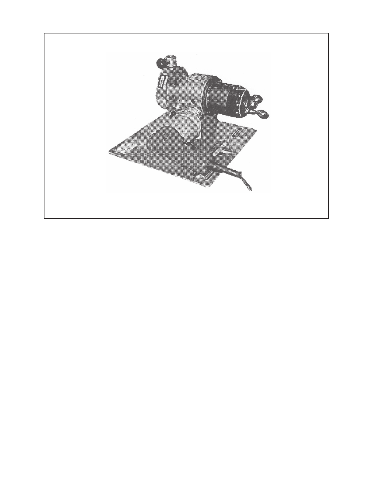
TABLE OF CONTENTS
CUSTOMER MESSAGE Inside Front Cover
SAFETY PRECAUTIONS 3
92-0710 Rev. 040218
Micro-Feed Assembly for the 302
INSTALLATION 6
ILLUSTRATED PARTS BREAKDOWN 10
TOOL BIT RESHARPENING POLICY Inside Front Cover
WARRANTY INFORMATION Inside Front Cover
Page 2

Copyright 2004
Proprietary property of TRI TOOL Inc.
No reproduction, use, or duplication of the information
shown hereon is permitted without the express written
consent of TRI TOOL Inc.
Page 3
SAFETY PRECAUTIONS
IN GENERAL
When using rotating head cutting equipment, basic safety precautions should always
be followed to reduce the risk of personal injury.
Operate this tool only in accordance with specific operating instructions.
Do not override the deadman switch on the power unit. Locking down, ob-
WARNING:
DRESS CONSIDERATIONS
structing, or in any way defeating the deadman switch on the power drive unit
may result in serious injury.
Micro-Feed Assembly for the 302
Use standard safety equipment. Hard hats, safety shoes, safety harnesses, protective clothes, and other safety devices should always be used when appropriate.
Use safety glasses. Do not operate cutting tools without eye protection.
Dress properly. Do not wear loose clothing or jewelry. They can be caught in rotating and moving parts. Avoid slippery floors or wear nonskid footwear. If you have
long hair, wear protective hair covering to contain it.
WORK AREA
Keep the work area clean. Cluttered work areas and benches invite injuries.
Consider the work area environment. Keep the area well lit. Keep electrical cords,
cables, rags, rigging straps, and etc. clear of rotating equipment. Do not use powercutting tools in the presence of flammable liquids and gasses.
Keep visitors away. Do not let visitors or untrained personnel at or near operating
tools. Enforce eye protection requirements for all observers.
Do not over reach. Keep proper footing at all times.
Stay alert. Watch what you are doing. Use common sense. Do not operate tools
when you are tired.
92-0710 : Rev. 040218
3
Page 4

TRI TOOL INC.
TOOL CARE
Maintain tools with care. Keep tools in good operating condition. Sharp tool bits
perform better and safer than dull tool bits. Well maintained tools function properly
when needed.
Check for damaged parts. If a tool has malfunctioned, been dropped or hit, it must
be checked for damage. Run no-load tests and feed function checks. Do a complete visual inspection.
Electric motors. Use only with proper AC voltage power sources and observe all
normal electric shock hazard procedures.
Do not abuse power and control cords. Pulling or running over cords and cables
can result in electrical shock hazards and malfunctions. Keep control and power
cords out of all cutting fluids and water.
Hydraulic drives. Observe proper procedures for electrically driven power sources.
Avoid damage to hydraulic lines. Keep quick-disconnects clean. Grit contamination
causes malfunctions.
Air tools. Check the exhaust muffler. Broken or damaged mufflers can restrict air
flow or cause excessive noise. Use air motors only with a filtered, lubricated and
regulated air supply. Dirty air, low-pressure air or over pressure air will cause malfunctions, including delayed starting.
AREA EQUIPMENT
Secure work. Whenever possible use clamps, vises, chains and straps to secure
pipe.
Make sure the tool is secured; it is safer to have both hands free to operate the tool.
TOOL USE
Use the right tool and tool bit for the job. Do not use a tool, which is incorrect for the
job you are doing.
Keep the tool bits fully engaged in the tool bit holders. Loose bits are a safety hazard.
4
92-0710 : Rev. 040218
Page 5

Micro-Feed Assembly for the 302
Disconnect power supply during setup and maintenance. Use all ‘Stop’ or Shut off’
features available when changing or adjusting tool bits, maintaining the tool, or when
the tool is not in use.
Remove adjusting keys and wrenches before applying power to the equipment.
Develop a habit of checking the tool before turning it on to make sure that all keys
and wrenches have been removed.
Do not force tools. Tools and tool bits function better and safer when used at the
feed and speed rate for which they were designed.
Do not reach into rotating equipment. Do not reach into the rotating head stock to
clear chips, to make adjustments, or to check surface finish. A machine designed to
cut steel will not stop for a hand or an arm.
Handle chips with care. Chips have very sharp edges and are hot. Do not try to pull
chips apart with are hands; they are very tough.
Avoid unintentional starts. Do not carry or handle tools with your hand on the operating switches or levers. Do not lay the tool down in a manner that will start the
drive. Do not allow the tool to flip around or move when adjusting or changing tool
bits.
Store idle tools properly. Disconnect tools from the power source and store in a safe
place. Remove tool bits for safe handling of the tool.
92-0710 : Rev. 040218
5
Page 6
TRI TOOL INC.
INSTALLATION
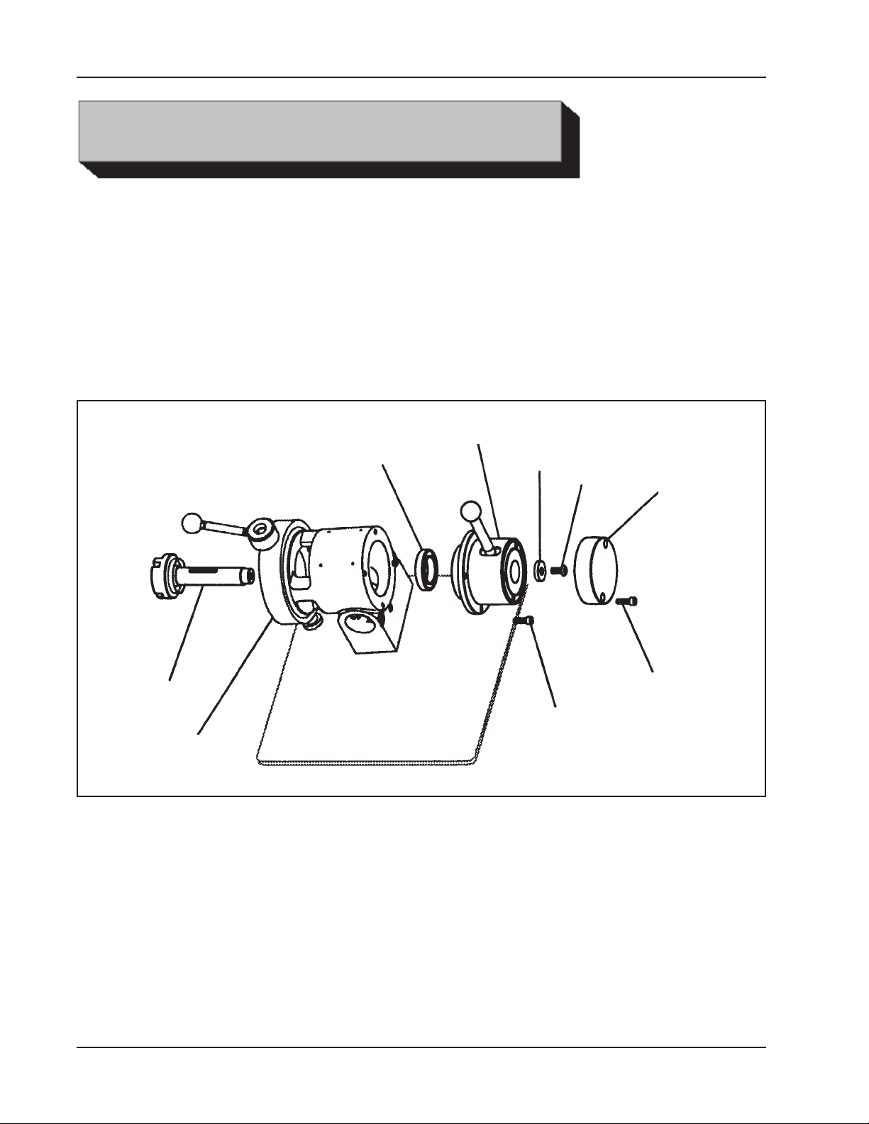
REMOVING THE LEVER FEED ASSEMBLY
In order to install the micro-feed assembly onto the back of the Model 302, the
existing lever feed assembly must be removed.
Remove the two (2) cap screws from the back of the cover.
Remove the cover from the lever feed assembly.
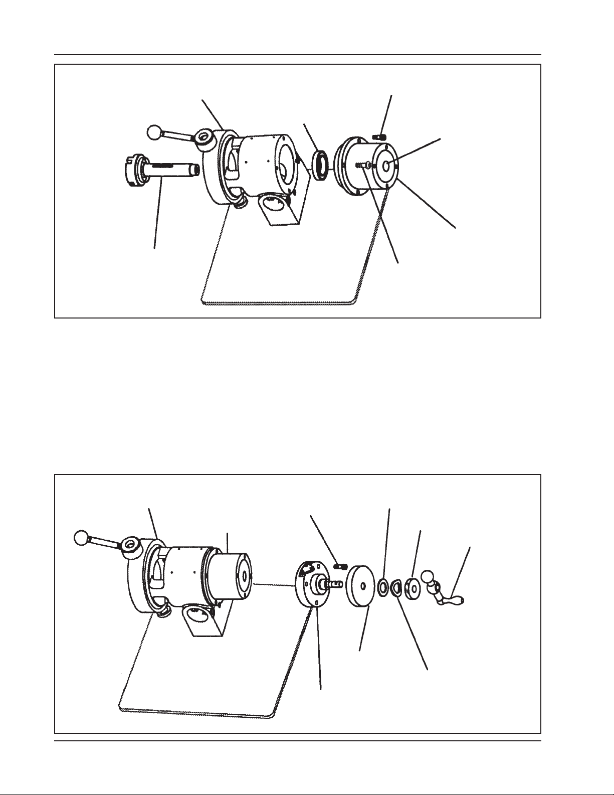
Lever Feed System
Ball Bearing
Feed Shaft
Main Housing
Remove the Button head screw and capture washer from the end of the feed shaft.
Capture
Washer
Cap Screw (4)
Button
Head
Screw
Cover
Cap Screw (2)
Remove the four (4) cap screws from the flange on the lever feed system.
The lever feed assembly may now be removed.
The ball bearing on the end of the feed shaft may come off if it is loose, otherwise
leave it in place.
6
92-0710 : Rev. 040218
Page 7
PREPARE THE MICRO-FEED ASSEMBLY
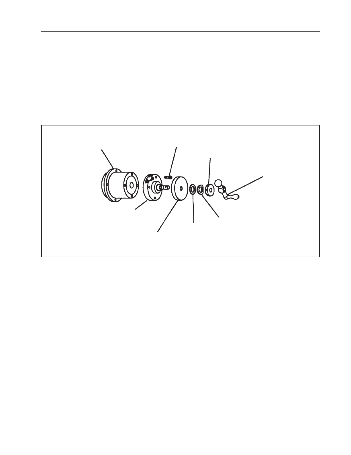
Loosen the set screw from the feed handle.
Remove the feed handle from the micro-feed assembly.
Remove the lock knob from the end of the feed shaft.
Remove the thrust washer and the spring washer from the end of the feed shaft.
Micro-Feed Assembly for the 302
Feed Adapter
Feed Cover
Indicator Dial
Remove the indicator dial from the feed shaft.
Remove the four (4) cap screws from the feed cover.
Rotate the feed screw to remove the feed cover and the feed screw from the back of
the feed adapter.
Cap Screw (4)
Thrust
Washer
Lock Knob
Feed Handle
Spring
Washer
INSTALLING THE MICRO-FEED ASSEMBLY
The ball bearing in the front of the feed adapter is the same as the one in the back
of the Model 302 main housing.
Only one ball bearing is required, remove the one or the other.
92-0710 : Rev. 040218
7
Page 8
TRI TOOL INC.
Main Housing
Ball Bearing
Feed Shaft
Cap Screw (4)
Access to the
Button Head
Screw
Feed Adapter
Button Head Screw
Slide the feed adapter onto the end of the main housing.
Using a hex wrench through the middle of the feed adapter, rotate the button head
screw to thread it into the end of the feed shaft inside of the main housing.
Once the button head screw is tight, then install the four (4) cap screws, which hold
the feed adapter to the main housing.
Reinstall the feed cover by rotating the feed screw to thread it into the feed spacer.
Thrust
Main Housing
Cap Screws (4)
Feed Adapter
Indicator Dial
Feed Cover
Washer
Lock Knob
Feed
Handle
Spring
Washer
8
92-0710 : Rev. 040218
Page 9

Micro-Feed Assembly for the 302
Rotate the feed cover so that the index pointer is on the top.
Reinstall the four (4) cap screws that hold the feed cover to the back of the feed
adapter.
Reinstall the indicator dial onto the feed shaft.
Reinstall the thrust washer and then the spring washer onto the end of the feed
shaft.
Thread the lock knob onto the end of the feed shaft.
Slide the feed handle onto the end of the feed shaft and rotate it so that the set
screw is over the flat.
Tighten the set screw in the feed handle to lock the feed handle onto the feed shaft.
92-0710 : Rev. 040218
9
Page 10
TRI TOOL INC.
ILLUSTRATED PARTS BREAKDOWN
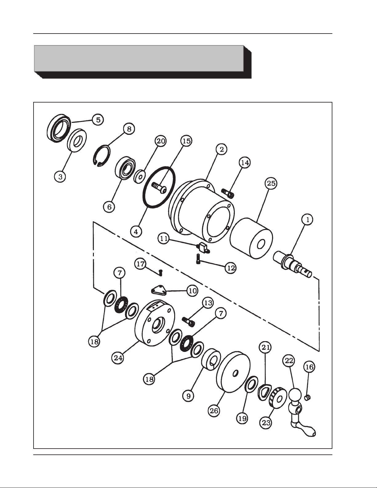
MICRO-FEED ASSEMBLY (P/N 82-0122)
10
92-0710 : Rev. 040218
Page 11

Micro-Feed Assembly for the 302
Parts List, Micro-Feed Assembly (P/N 82-0122)
Item Part
No. No. Description Qty
1. 20-0654 SHAFT, FEED 1
2. 27-0574 ADAPTER, FEED 1
3. 28-0231 SEAL 1
4. 28-0234 O-RING 1
5. 29-0011 BEARING, BALL 1
6. 29-0020 BEARING, BALL 1
7. 29-0067 BEARING, THRUST ROLLER 2
8. 30-1089 RING, RETAINING 1
9. 30-2544 COLLAR, SHAFT 1
10. 30-2621 INDEX, POINTER 1
11. 31-0169 KEY 1
12. 33-0011 SCREW, CAP, #6-32 X .25" 2
13. 33-0041 SCREW, CAP, 1/4-20 X .88" 4
14. 33-0040 SCREW, CAP, 1/4-20 X .75" REF
15. 33-0292 SCREW, BUTTON HEAD, 5/16-18 X .63" 1
16. 33-0513 SCREW, SET, 5/16-18 X .31", CUP 1
17. 33-1448 SCREW, BUTTON HEAD, #5-40 X .25" 2
18. 34-0106 WASHER, THRUST 4
19. 34-0163 WASHER, THRUST 1
20. 34-0278 WASHER, CAPTURE 1
21. 34-0325 WASHER, SPRING 1
22. 41-0142 HANDLE, FEED 1
23. 42-0172 KNOB, LOCK 1
24. 24-1524 PLATE, END 1
25. 44-0476 SPACER, FEED 1
26. 50-0022 DIAL, INDICATOR 1
NOT SHOWN
36-0008 WRENCH, L, 3/16" HEX 1
36-0021 WRENCH, T, 3/16" HEX 1
92-0710 : Rev. 040218
11
 Loading...