

Trio Motion Technology PCI 208 User Manual
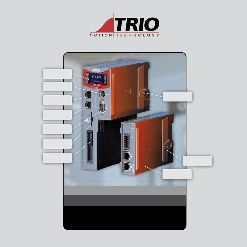
BACKLIT DISPLAY
RS232 + RS485
ETHERNET
PROGRAMMING
SYNC PORT
SYNC ENC ODER
SD CARD
I/O, CAN, POWER,
ANALOGUE
COMMON EARTHING
FOR IMPROVED
NOISE REJECTION
FIRST EXPANSION
MODULE
MOTION COORDINATOR
MC464
Quick Connection Guide
EASY RELEASE
EXPANSION COVER

BACKLIT DISPLAY
ETHERNET
PROGRAMMING
SYNC PORT
SD CARD
I/O, CAN, POWER,
ANALOGUE
RS232 + RS485
SYNC ENC ODER
FIRST EXPANSION
MODULE
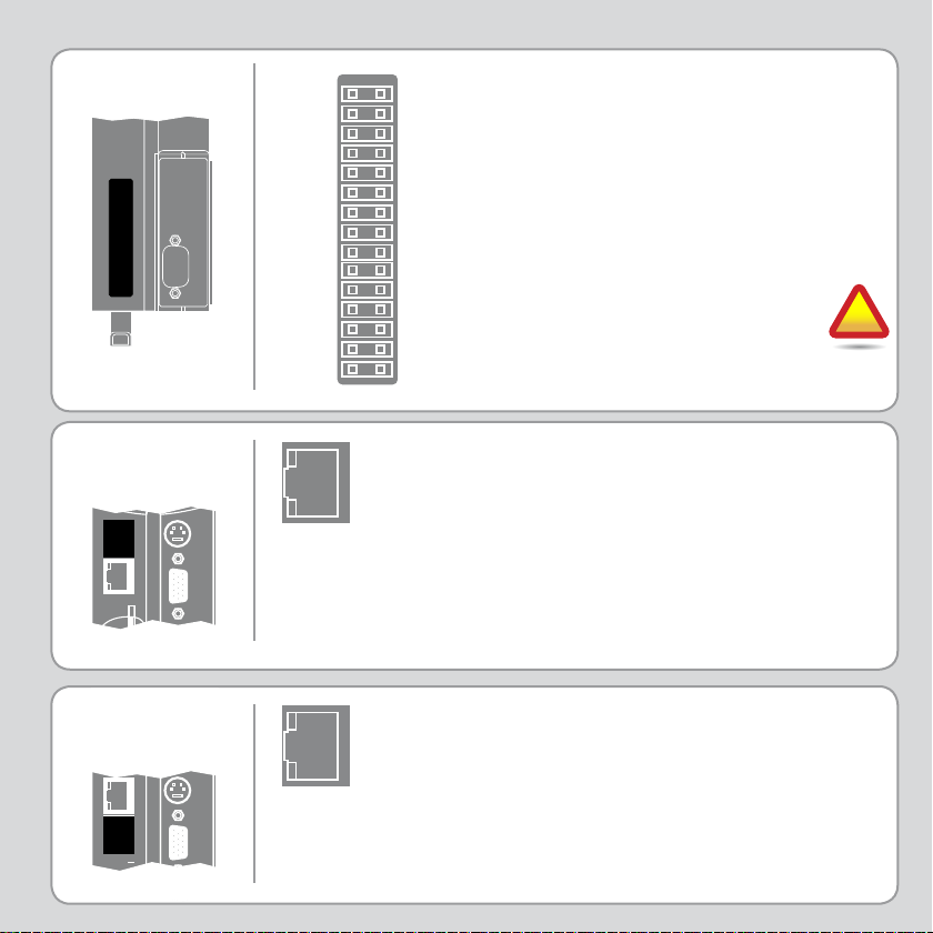
I/O CONNE CTOR
0V AIN
AIN0
AIN1
WDOG+
WDOG-
0V I/ O
0V SUPPLY
0V CAN/ AIN
CAN LOW
CAN EARTH
CAN HIGH
24V CAN/AIN SUPPLY
I 0
I 1
I 2
I 3
I 4
I 5
I 6
I 7
I/O8
I/O9
I/O10
I/O11
I/O12
I/O13
I/O14
I/O15
24V I/O SUPPLY
24V SUPPLY
high density input connector are
used to provide the 24V dc power
to the MC464. A 24V dc, Class 2
transformer or power source must
be provided.
The 2 pins above the 24V dc supply
are to power the I/O 24 Volts.
The MC464 is grounded via
the metal chassis. It MUST
be installed on an unpainted
metal plate or DIN rail which is
connected to earth.
!
The bottom 2 pins of the 30 way
RJ45
CONNECTOR
(TOP)
RJ45
CONNECTOR
(BOTTOM)
A standard ethernet connector is provided
for use as the primary programming
interface.
The Trio programming software, Motion
Perfect 2, must be installed on a Windows
based PC that is fi tted with an Ethernet
connection. The IP address is displayed on
the MC464 display for a few seconds after
power-up or when an Ethernet cable is
plugged in.
A standard ethernet connector is provided to
allow synchronisation between units.
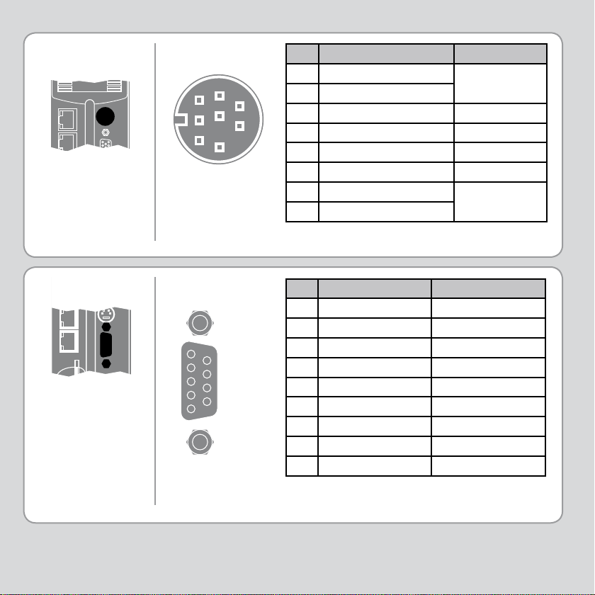
SERIAL
CONNECTIONS
SYNC ENCODER
CONNECTIONS
8 Way MiniDIN
3
6
4
7
8
5
9 Way D-Type
1
2
3
4
5
6
7
8
9
Pin Function Note
1 RS485 Data In A Rx+
1
2
2 RS485 Data In B Rx3 RS232 Transmit Serial Port #1
40V Serial
5 RS232 Receive Serial Port #1
6Internal 5V
7 RS485 Data Out Z Tx8 RS485 Data Out Y Tx+
Pin Encoder Pulse & Direction
1 Enc. A Step +
2 Enc. /A Step 3 Enc. B Direction +
4 Enc. /B Direction 5 0V Encoder 0V Stepper
6 Enc. Z Enable +
7 Enc. /Z Enable 85V* 5V*
Registration Input (5V) Registration Input (5V)
9
* 5V supply is limited to 150mA.
Serial Port #2
Serial Port #2
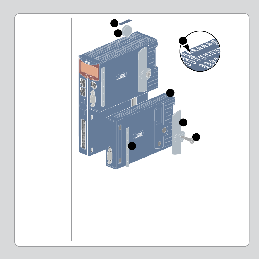
ADDING
EXPANSION
MODULES AND
BATTERY
D
E
F
C
B
A
B
Unscrew the lower retaining fi xing (A) using the supplied tool or a
coin.
Remove the covers from the module (B).
Swing the expansion module (C) out from the rear and unclip from
the front end.
Replacing the module is the reverse of the procedure.
To replace the battery, insert screwdriver under the frontmost
ventilation slot (F) and prize off the battery cover (D) and pull the
battery ribbon to lift the battery (E) from the MC464. Replacing is
the reverse of the procedure.
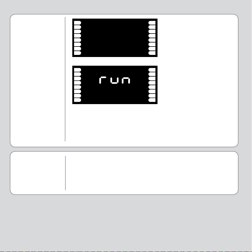
LCD DISPLAY
0
1
2
3
4
5
6
7
OFF
8
9
10
11
12
13
14
15
Display at start-up
SOFTWARE
0
1
2
3
4
5
6
7
ENABLE
8
9
10
11
12
13
14
15
Display with WDOG on
The IP address and subnet mask of the MC464 is shown on the LCD
display for a few seconds after power-up. The factory default IP
address is 192.168.0.250. This can be changed using the ETHERNET
command via Motion Perfect 2.
Trio recommend that you use the latest version of Motion Perfect
when using the MC464 (Minimum recommended version V2.4.0.16).
Software can be downloaded from www.triomotion.com.
 Loading...