

Page 1
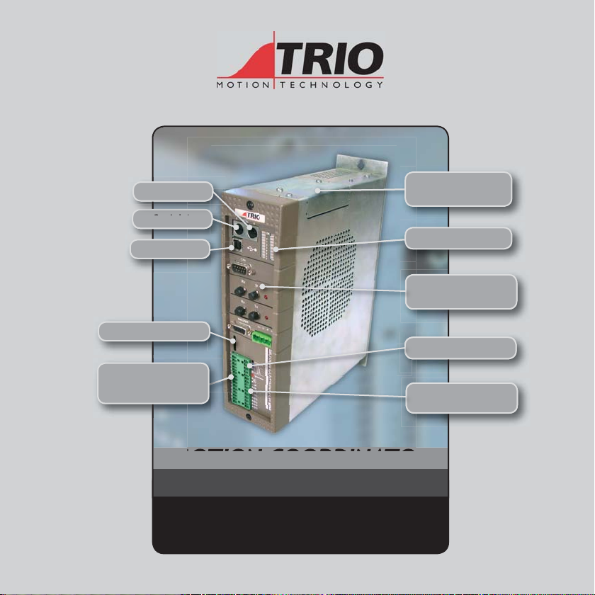
Serial B
Serial A
USB
Memory Slot
I/O Connector 1
24V Power / Analogue In
WDOG A / Inputs 0-7
Axis Expansion
Port
I/O Status
Daughter Board
Slots
CANbus Port
I/O Connector 2
WDOG B / I/O 8-15
MOTION COORDINAT OR
MC22 4
Quick Connection Guide
(Please refer to the Motion Coordinator Technical Reference Manual for Full Details)
Page 2
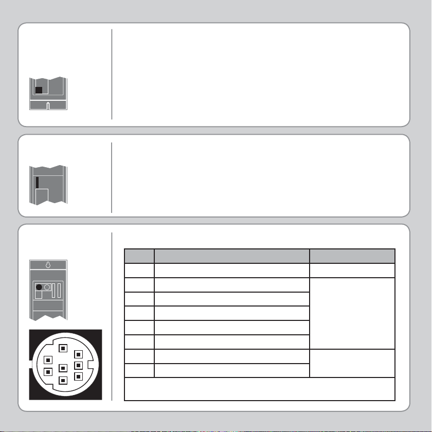
POWER
CONNECTOR
The bottom 2 pins of input connector 1 are used to provide the 24V
dc power to the MC224. A 24V dc, Class 2 transformer or power
source must be provided.
This 24 Volt input also supplies power to the I/O 24 Volts and any
daughter boards fi tted.
The MC224 is grounded via the metal case. It MUST be installed
on an unpainted metal plate which is connected to earth.
MEMORY CARD
SLOT
SERIAL
CONNECTIONS
5
8
2
7
4
1
6
3
A memory slot is provided for the NexFlash memory stick or
P396 SD Card adaptor. Available seperately.
Serial Connector A
Pin Function Note
1Internal 5V
2Internal 0V
3RS232 Transmit
4RS232 0V Serial Port #0
5RS232 Receive
6+5V output
7 Externally buffered output (TTL) For fi bre-optic
8 Externally buffered input (TTL)
Note: Port 0 is the default programming port for connection to the PC running Motion
Perfect.
adaptor.
Page 3
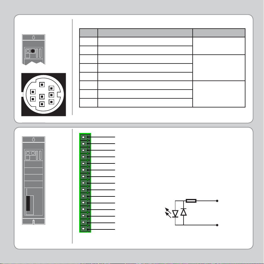
SERIAL
CONNECTIONS
5
2
4
1
3
Serial Connector B
Pin Function Note
1 RS485 Data In A Rx+
2 RS485 Data In B Rx-
Serial Port #2
3RS232 Transmit
4RS232 0V Serial Port #1
5RS232 RS485 0V
8
7
6
6Internal 5v
7 RS485 Data Out Z Tx- Serial Port #2
8 RS485 Data Out Y Tx+
I/O CONNE CTOR 1
Analogue Common
Analogue Input 0
Analogue Input 1
Enable A
Enable A
Input 0
Input 1
Input 2
Input 3
Input 4
Input 5
Input 6
Input 7
Power and I/O 24V
Power and I/O 0V
NOTE:
Analogue input circuit is powered from CANbus port 24V.
ANALOGUE INPUT:
Ain0: 0 to 10V
PAin1: 0 TO 10v
ENABLE A AND ENABLE B:
Solid state relay
100mA max
Optical
Input
Signal
6k8
Input Pin
0V Pin
Page 4
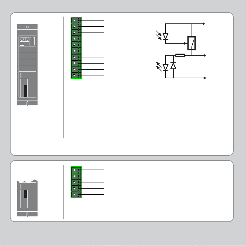
I/O CONNE CTOR 2
Enable B
Enable B
Input / Output 8
Input / Output 9
Input / Output 10
Input / Output 11
Input / Output 12
Input / Output 13
Input / Output 14
Input / Output 15
Optical
Output
Control
Signal
Optical
Input
Signal
6k8
24V Pin
Protected
Switch
Input / Output
Pin
0V Pin
Two internal relays are used to enable external amplifi ers when the
controller has powered up correctly and the system and application
software are ready. Each amplifi er enable is a single pole solid state
relay with a normally open “contact”. The enable relay contact will
be open circuit if there is no power on the controller OR a following
error exists on a servo axis OR the user program sets it open with
the WDOG=OFF command.
ALL STEPPER AND SERVO AMPLIFIERS MUST BE INHIBITED WHEN
THE AMPLIFIER ENABLE OUTPUT IS OPEN CIRCUIT
CANBUS
CONNECTOR
0V Power
CAN L
CAN Shield
CAN H
24V Power
NOTE: 24V power must be supplied from an external source.
Page 5
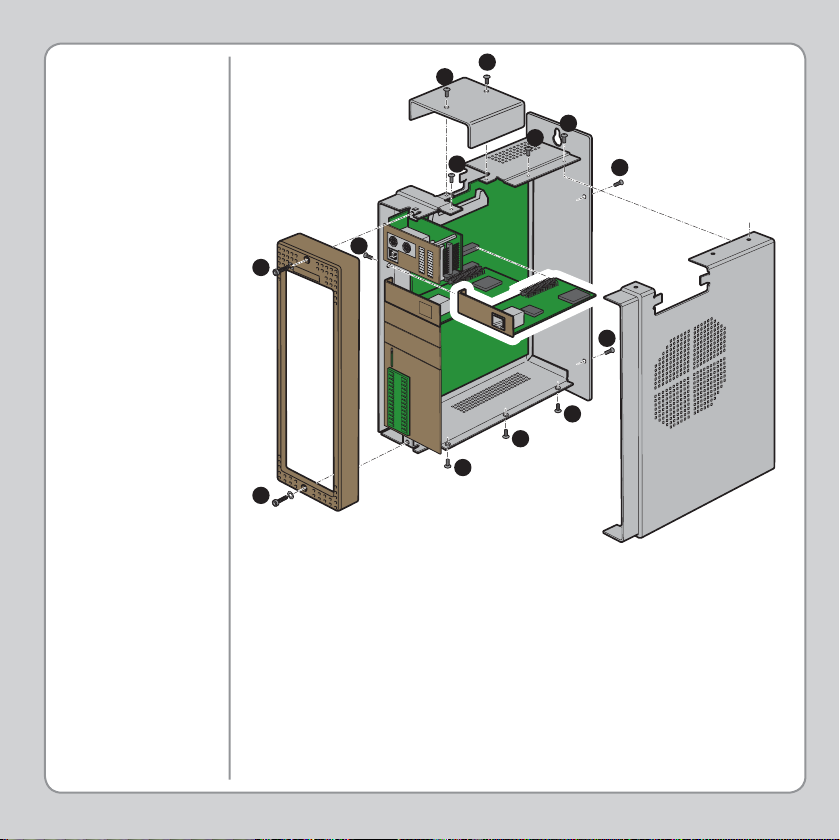
ADDING
DAUGHTER
BOARDS
B
B
C
C
C
D
A
C
C
A
C
C
C
Unscrew the 2 Allen screws (A) which secure the front moulding
cover and remove the cover.
Unscrew the top ribbon cable bus cover (B). If the ribbon cable is
connected, remove this by pushing the retaining levers outwards.
Unscrew the 8 screws (C) which secure the right hand side cover of
the module.
Unscrew the single screw (D) which secures the axis daughter board
to the left hand side of the module. This is located by the left hand
end of the axis daughter front panel.
The sequence is reversed after inserting any new modules.
Page 6
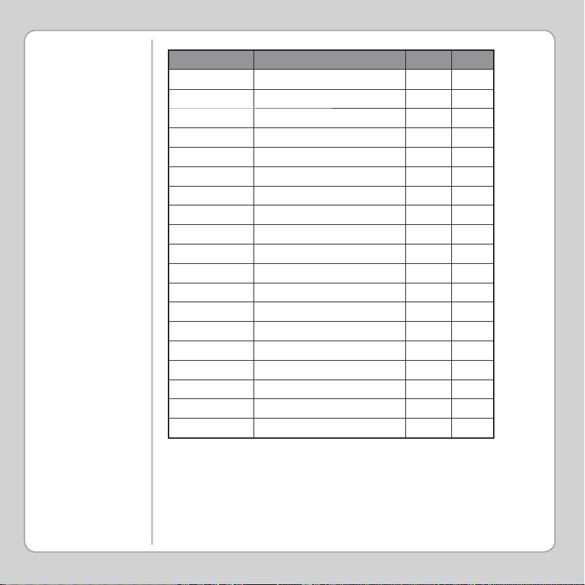
TABLE OF
DAUGHTER
BOARDS
Product code: Description MC224 P301
P200 Servo Encoder
P201 Enhanced Servo Encoder Y Y
P210 Servo Resolver Y Y
P220 Reference Encoder Y Y
P225 Analogue Input (8 x 16 bit) Y N
P230 Stepper Y Y
P240 Stepper Encoder Y Y
P242 Hardware Pswitch Y Y
P260 Analogue Output Y Y
P270 SSI Absolute Servo Y Y
P280 Differential Stepper Y Y
P290 CAN Y N
P291 SERCOS Y N
P292 3 Axis SLM Y N
P293 Enhanced CAN Y N
P295 USB Interface N N
P296 Ethernet Y N
P297 Profi bus Y N
P298 Ethernet IP Y N
Y
Y
NOTE: Only one of each of the following daughter boards may
be used in the MC224 at the same time; P296, P297 and P298.
Page 7
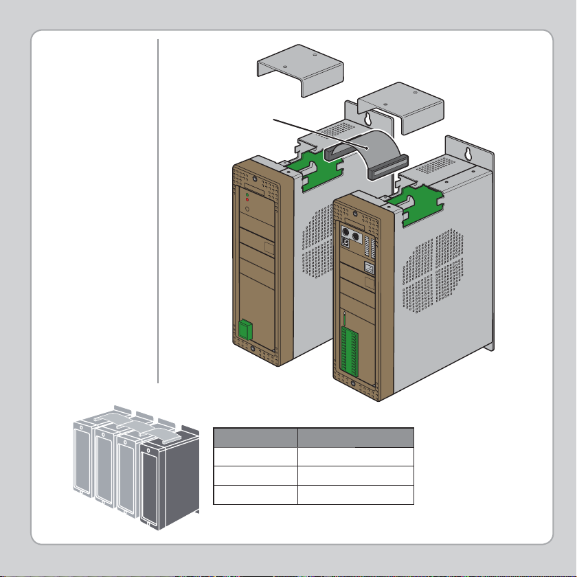
ADDING AXIS
EXPANDER
Ribbon Cable
Product code: Description
P355 2 way ribbon cable
P360 3 way ribbon cable
P365 4 way ribbon cable
NOTE:Up to 3 Axis Expanderss may be added to the MC224
Page 8
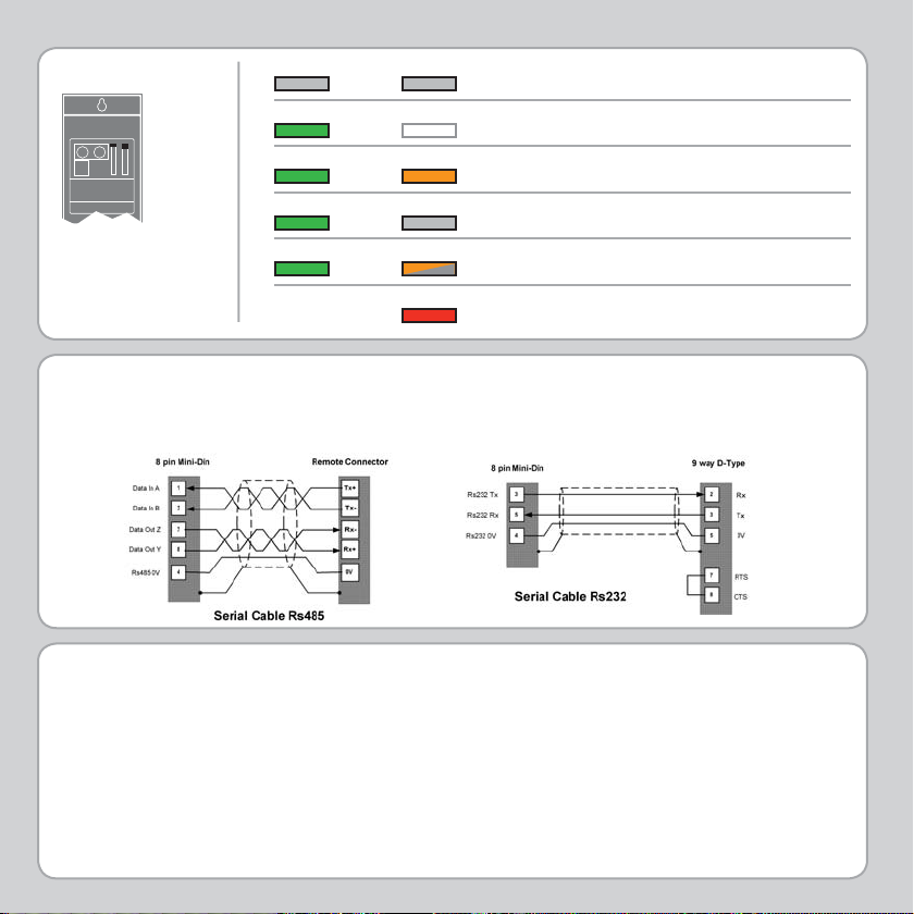
LED ERROR CODES
OK STA TUS
OK STA TUS
OK STA TUS
OK
OK STATUS
STA TUS
BAT
No power or critical fault
Normal operation
Enable relay open
Enable relay energised
Error in motion system (fl ashing)
Low Battery (change internal mem battery)
Good quality screened cables should be used for the serial ports and for the USB link. The serial
ports, USB port and CANbus port are not galvanically isolated, therefore the 0V return MUST be
connected to all peripheral devices. In addition, bond together the 0V (24V return) terminals of
all system components so as to minimise current fl owing in the serial cables.
Trio Motion Technology Ltd.
Shannon Way, Tewkesbury,
Glos. GL20 8ND. UK
Tel: +44 1684 292333
Fax: +44 1684 297929
Email: [email protected]
Website: www.triomotion.com
Trio Motion Technology LLC
1000 Gamma Drive, Suite 206,
Pittsburgh PA 15238, USA
Tel: +1 412 968 9744
Fax: +1 412 968 9746
Email: [email protected]
Website: www.triomotion.com
Trio Shanghai
Thompson Centre
228 Zhang Yang Road, A1105,
Pudong New Area, Shanghai,
200122, China
Tel/Fax: +86-21-58797659
HP: +8613816137446
Email: [email protected]
Website: www.triomotion.com
quick start v1-may 2007
 Loading...