

Trio Motion Technology CAN 16-I/O Modules, P315 Reference Manual

CHAPTER
CHAPTER 0I/O MODULES


Motion Coordinator PCI 208 Technical Reference Manual
Input/Output Modules
General Description
Trio can supply a range of Input/Output Modules for the PCI 208. The Motion
Coordinator controllers allow for I/O expansion by having a CAN interfaces. The
PCI 208 has 2 built-in CAN interfaces of which channel A is always used for Trio I/
O modules. This allows the I/O modules to form a network up to 100m in length.
The Trio I/O modules use a dedicated protocol which must be run on a physically
separate CAN interface to CANopen or DeviceNet. If the built-in Trio protocol is
not to be used it is necessary to set the CANIO_ADDRESS value to a value other
than it’s default of 32.
Product: Product Code:
CAN 16-I/O Module
CAN Analog Input Module
P315
P325
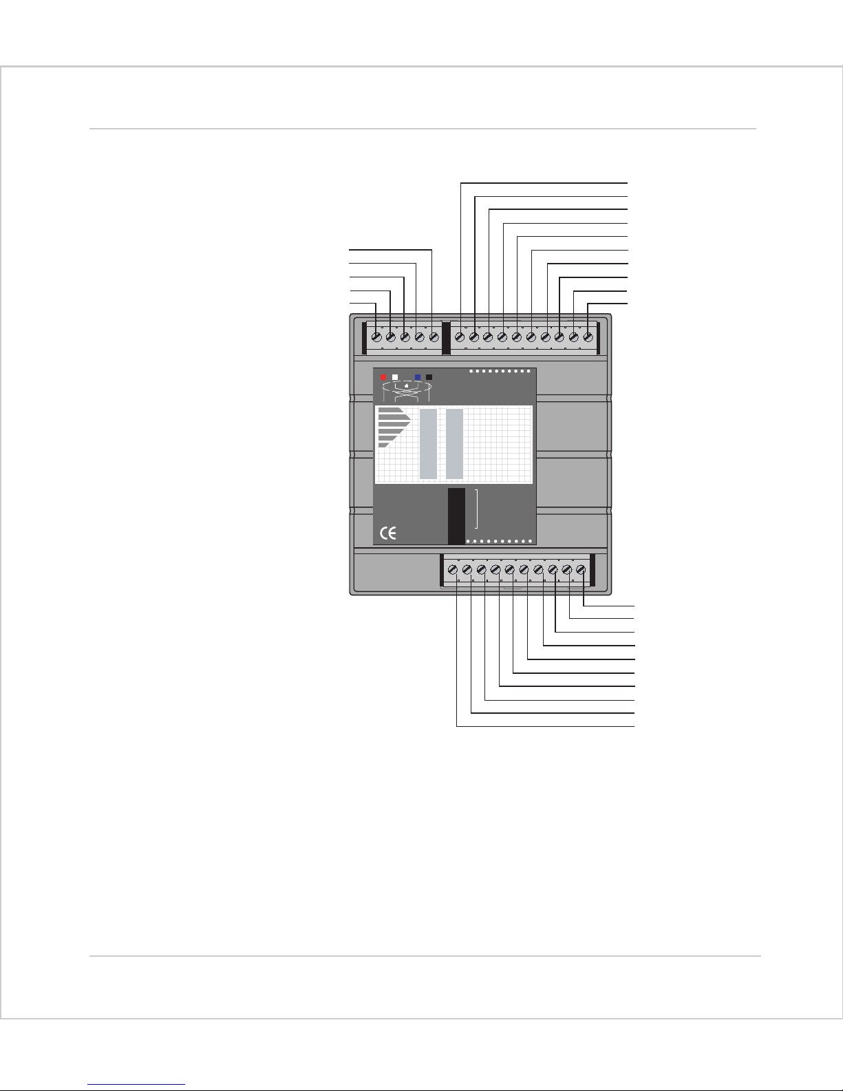
CAN 16-I/O Module (P315)
The CAN 16-I/O Module allows the 24 volt digital inputs and outputs of the
Motion Coordinator to be expanded in blocks of 16 bi-directional channels.
Up to 16 CAN 16-I/O Modules may be connected allowing up to 256 I/O channels
in addition to the internal channels built-in to the PCI 208 Motion Coordinator.
Each of the 16 channels in each module is bi-directional and can be used either as
an input OR as an output.
Convenient disconnect terminals are used for all I/O connections.
I/O Modules 5-3
Input/Output Modules
Trio Motion Technology
(Black) V(Blue) CAN _L
SHIELD
(White) CAN_H
(Red) V+
MS NS
P165
OFF
PR
DR
0
1
2
3
4
5
6
7
7654321 00v 24v
8
9
Trio
10
11
12
13
14
15
CAN 16-I/O
1
2
4
NODE
ADDRESS
8
16
32
10 11 12 13 14 15 24v Ov98
0v for IO 0-7
24v for IO 0-7
IO 7
IO 6
IO 5
IO 4
IO 3
IO 2
IO 1
IO 0
I/O Connections:
5-4 I/O Modules
Input/Output Modules
0v for IO 8-15
24v for IO 8-15
IO 15
IO 14
IO 13
IO 12
IO 11
IO 10
IO 9
IO 8
The CAN 16-I/O Module has 3 disconnect terminal connectors:
• DeviceNet physical format 5 way CAN connector
• Input/Output Bank 0 - 7 and power supply for bank 0 - 7 on 10 way
connector
• Input/Output Bank 8 - 15 and power supply for bank 8 - 15 on 10 way
connector.
Motion Coordinator PCI 208 Technical Reference Manual
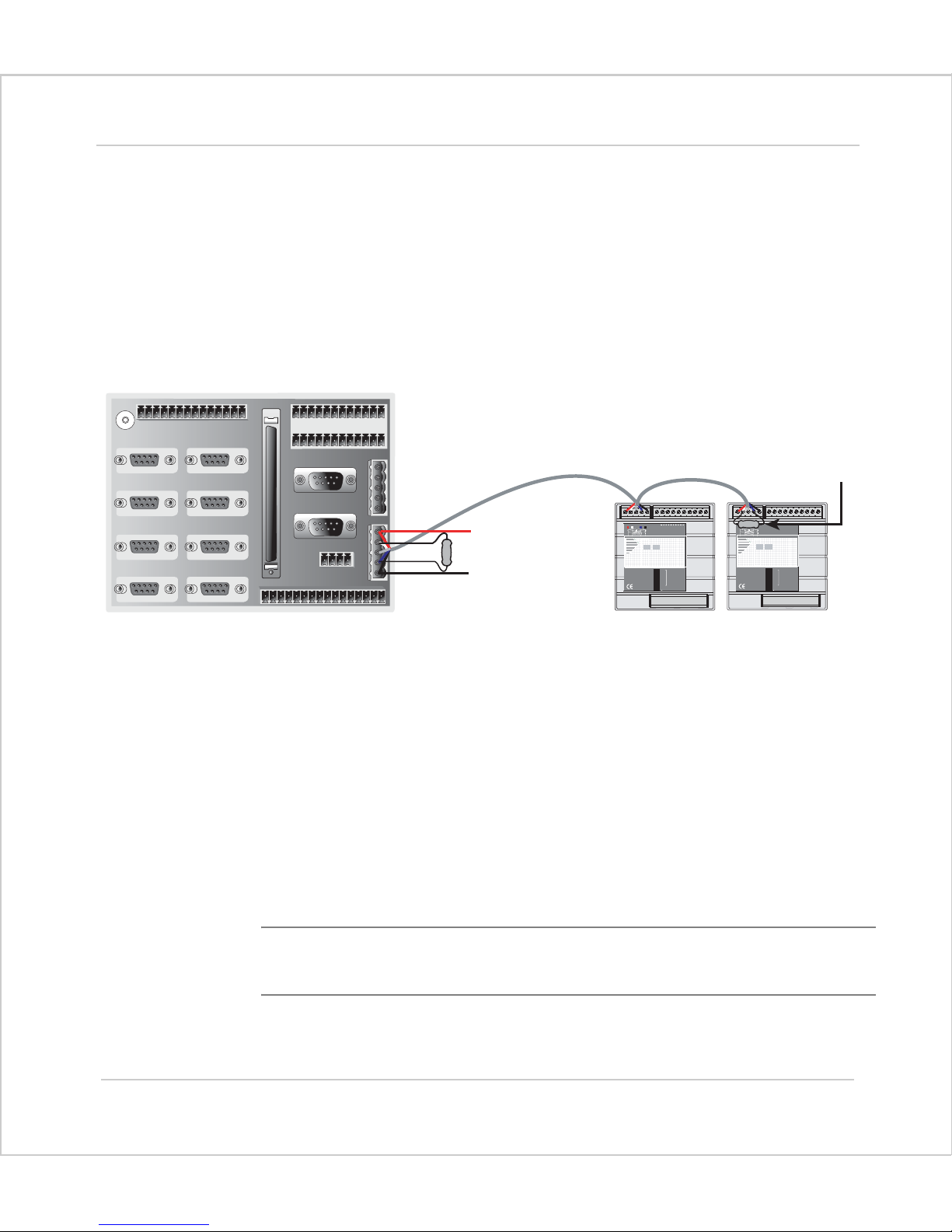
Bus Wiring
X9
Axis Ø Axis 1
Axis 2 Axis 3
Axis 4 Axis 5
Axis 6 Axis 7
The CAN 16-I/O Modules and the Motion Coordinator are connected together on a
network which matches the physical specification of DeviceNet running at
500kHz. The network is of a linear bus topology. That is the devices are daisychained together with spurs from the chain. The total length is allowed to be up
to 100m, with drop lines or spurs of up to 6m in length. At both ends of the network, 120 Ohm terminating resistors are required between the CAN_H and CAN_L
connections. The resistor should be 1/4 watt, 1% metal film.
X10
X17
765432100v24v
NS
CAN Analog
Inputs
1
2
4
8
16
32
Trio
NODE
ADDRESS
120 ohm
Terminating
Resistor
X12
X13
X14
X11
X15
X16
24v
120 ohm
Terminating Resistor
0v
7654321 00v24v
Trio
018
NS
MS
9
CAN Analog
P325
Inputs
OFF
1
2
NODE
4
ADDRESS
8
16
32
PR
DR
018
MS
9
P325
OFF
PR
DR
Note:
The cable required consists of:
Blue/White 24AWG data twisted pair
+ Red/Black 22AWG DC power twisted pair
+ Screen
A suitable type is Belden 3084A.
The CAN 16-I/O modules are powered from the network. The 24 volts supply for
the network must be externally connected. The Motion Coordinator does NOT
provide the network power. In many installations the power supply for the
Motion Coordinator will also provide the network power.
It is recommended that you use a separate power supply from that used to
power the I/O to power the network as switching noise from the I/O devices
may be carried into the network.
I/O Modules 5-5
Input/Output Modules
 Loading...