

Trio Motion Technology MC4N-ECAT User Manual
Ethernet Programming
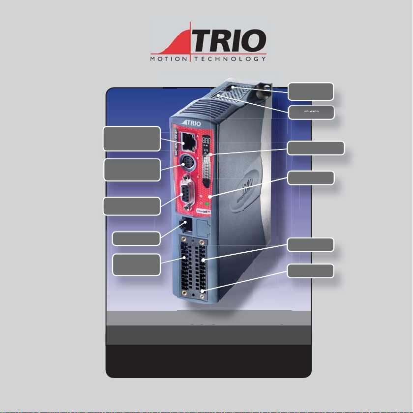
SD C
ard
P
And Comms Port
Can Port
SD Card
Status Display
RS232 / RS485
Flexible axis port
Ethercat port
8 INPUTS
Status LEDs
8 I/O ports
Power 24V DC
MOTION COORDINATOR
MC4 N - E CAT
Quick Connection Guide
This guide must be used in conjunction with the
Technical Reference Manual
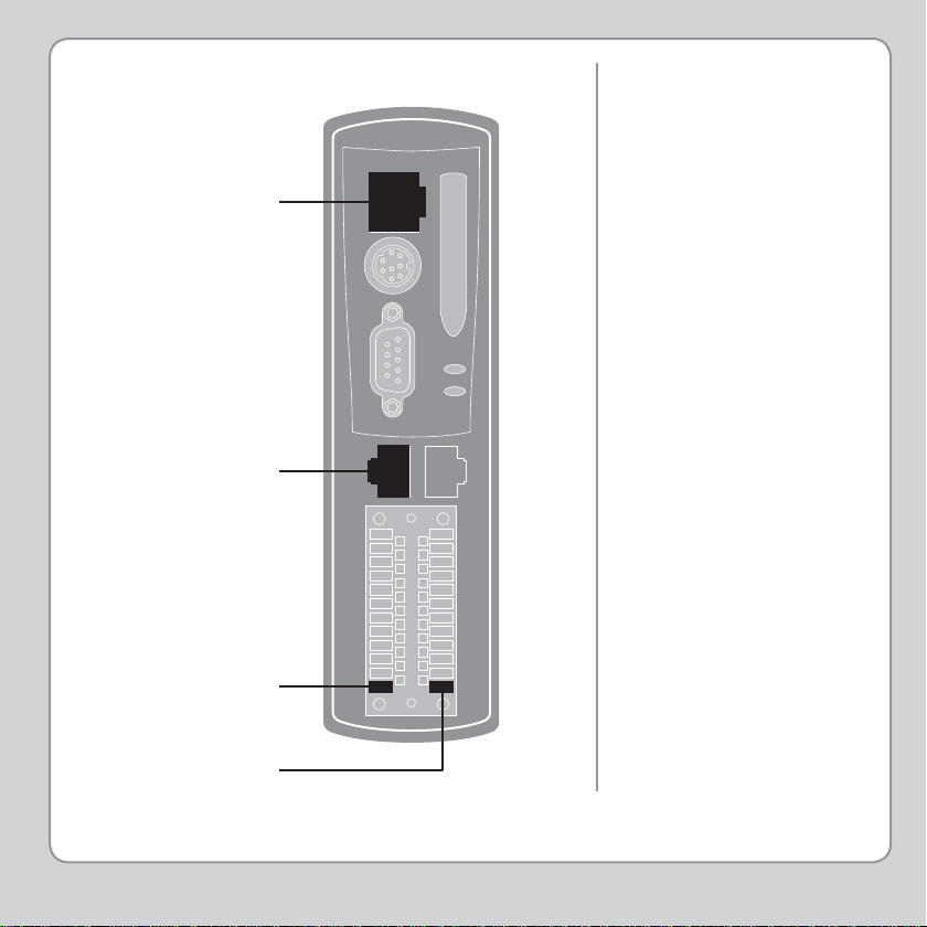
MINIMUM
CONNECTIONS
Programming port
EtherCAT port
OPTIONAL
CONNECTIONS
Serial ports
Auxiliary Flexible Axis Port
I/O Connections
Enable (Watchdog)
CAN port
0V
24V
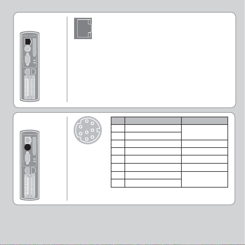
RJ45
CONNECTOR
A standard Ethernet connector is provided for use as
the primary programming interface.
The Trio programming software, Motion Perfect v3,
must be installed on a Windows based PC that is
fi tted with an Ethernet connection. The IP address is
displayed on the MC4N display for a few seconds after
power-up or when an Ethernet cable is plugged in.
Ethernet cable must be CAT 5 or better.
The Standard Ethernet connection may also be used for
Ethernet-IP, Modbus and other factory communications.
See back page for set-up details.
SERIAL
CONNECTIONS
3
1
2
6
7
4
8
5
Pin Function Note
1 RS485 Data In A Rx+
2 RS485 Data In B Rx3 RS232 Transmit Serial Port #1
4 0V Servo/Encoder
5 RS232 Receive Serial Port #1
6 5V Output 150mA max*
7 RS485 Data Out Z Tx8 RS485 Data Out Y Tx+
* Current shared with encoder port
Serial Port #2
Serial Port #2
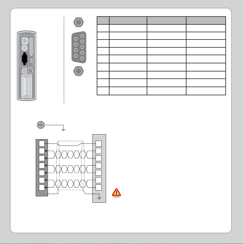
FLEXIBLE AXIS
PORT
SHIELDING THE
PORT
SHIELD SCREW
ENCODER INPUT (9 WAY D-TYPE)
5
Enc 0V
Quadrature A
Quadrature B
Z Marker Pulse
Encoder Output 0V MUST be connected to pin 5
*
1
2
3
4
6
7
CONNECTOR SHELL
Pin Encoder Stepper Axis Absolute Encoder
1 Enc. A Step + Clock
2 Enc. /A Step - /Clock
9
8
7
6
5
4
3 Enc. B Direction + --------
3
4 Enc. /B Direction - --------
2
5 0V Serial/Encoder 0V Serial/Encoder 0V Serial/Encoder
1
6 Enc. Z Enable + Data
7 Enc. /Z Enable - /Data
8 5V* 5V* 5V*
9 Not Connected Not Connected Not Connected
*Current limit is 150mA max shared with serial port.
Ensure that:
1. The shield screw is grounded as close to the
MC4N as possible.
*
A+
A-
B+
B-
Z+
Z-
screens.
3. Pin 5 of Encoder/Stepper plug is connected
to 0V on drive.
4. Encoder cable screen is clamped to 9 way D
shell.
5. The MC4N 24V supply has common 0V with
the drive(s).
2. 0V connection is NOT used for terminating
0V
When wiring MC4N Stepper output to a
differential input stepper drive, use the 0V
and shield connections shown for the encoder.
The stepper drive must have its common 0V
connected to the MC4N.
 Loading...