

Trio Motion Technology MC403 User Manual
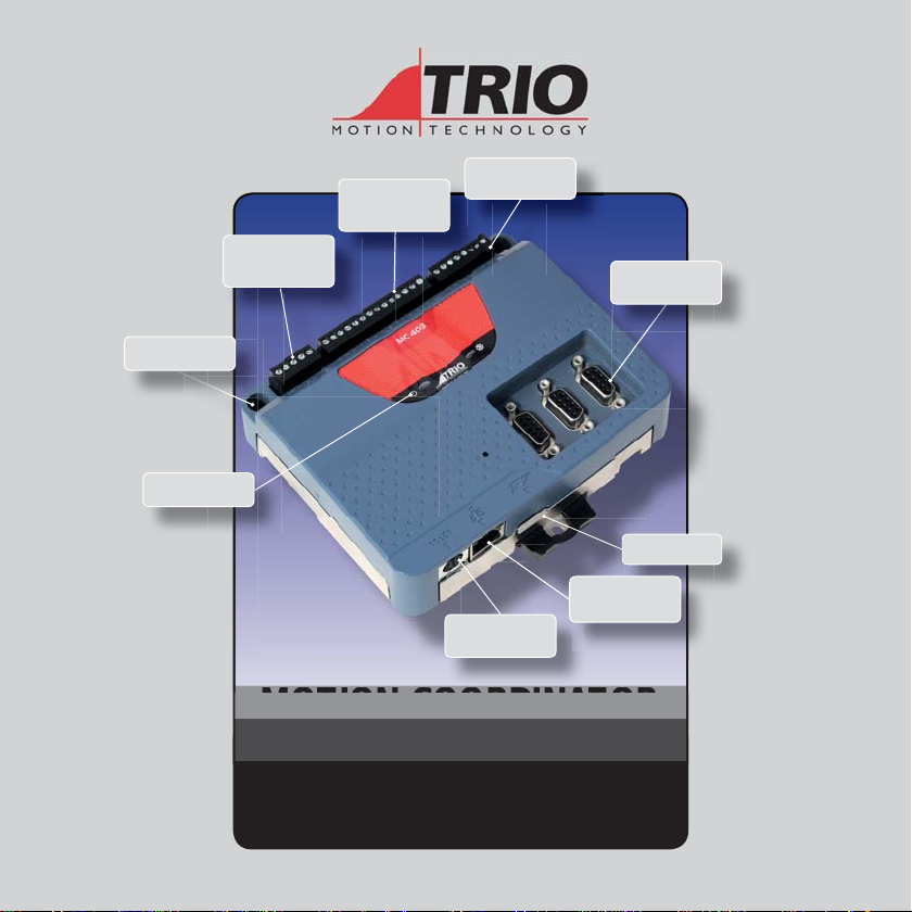
PANEL MOUNT OR DIN
RAIL MOUNT
STATUS LEDS
2 ANALOGUE INPUTS AND
2 VOLTAGE OUTPUT AND
WDOG RELAY
RS232 / RS 485
MODBUS-RTU,
HOSTLINK OR US ER
PROGRAMMABLE
PROGRAMMING, MODBUS-
TCP, ETHERNET IP
CAN PORT FOR TRIO CA N
I/O, DEVICENET SL AVE,
CANOPEN OR USER
PROGRAMMABLE
8 DIGITAL INPUTS
INCLUDING
6 X REGISTRATION IN PUTS
AND 4 BI-DIRECTI ONAL I/O
MOTION C OORDINAT OR
MC403 / MC40 3 -Z
3 ENCODER CONNEC TIONS
(6MHZ) OR DRIVE A S
STEPPER OUTP UTS
(2MHZ)
MICRO SD CARD
ETHERNET
Quick Connection Guide
(Please refer to the Motion Coordinator Technical Reference Manual for Full Details)
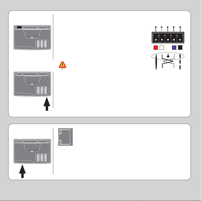
5-WAY
CONNECTOR
MC 403
This is a 5 way 3.5mm pitch connector. The
connector is used both to provide the 24
Volt power to the MC403(-Z) and provide
connections for I/O expansion via Trio’s CAN
I/O expanders. A 24V dc, Class 2 transformer or
power source must be provided as this powers
the unit.
This 24 Volt input is internally isolated from the
I/O 24 Volts and the +/-10V voltage outputs.
L
H
-
CAN
CAN
V+
SHIELD
V-
MC 403
RJ45
CONNECTOR
MC 403
The 24V (V+) and 0V (V-) MUST be connected
as they power the MC403(-Z). The MC403(-Z)
is grounded via the metal chassis. A screw is
provided on the chassis at the rear to allow
an earth strap connection if needed. It MUST
be installed on an unpainted metal plate or
DIN rail which is connected to earth. The CAN
connections are optional.
A standard Ethernet connector is provided for use as
the primary programming interface.
The Trio programming software, Motion Perfect, must
be installed on a Windows based PC that is fi tted with
an Ethernet connection.
Ethernet cable must be CAT 5 or better.
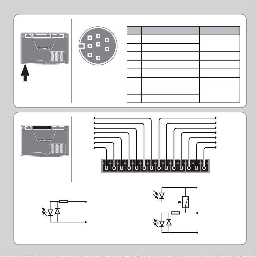
SERIAL
CONNECTIONS
MC 403
Serial Connector
3
6
1
4
7
2
8
5
Pin Function Note
1 RS485 Data In A Rx+
2 RS485 Data In B Rx-
Serial Port #2
3 RS232 Transmit Serial Port #1
40V Serial
5 RS232 Receive Serial Port #1
65V
7 RS485 Data Out Z Tx8 RS485 Data Out Y Tx+
Serial Port #2
I/O CONNE CTOR 1
MC 403
Input 4
Input 3
Input 2
Input 1
Input 0
I/O 24V
I/O 0V
24V Power / Inputs / I/O
Optical
Output
Control
Optical
Input
Signal
6k8
Input Pin
0V Pin
Any input, 0 - 5, may be mapped to any axis as a registration input.
Signal
Optical
Input
Signal
6k8
24V Pin
Protected
Switch
Input / Output Pin
0V Pin
Input 5
Input 6
Input 7
I/O 8
I/O 9
I/O 10
I/O 11
 Loading...