

Trio Motion Technology MC302x User Manual
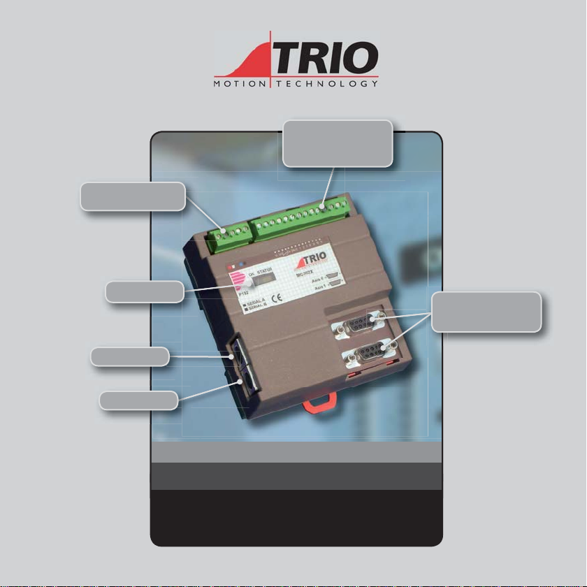
5 Way Connector
Power / CANbus
Analogue Output,
WDOG and
I/0 Connector
Signal LEDS
Serial A
Serial B
Axes 0-1
Encoder Inputs /
StepperOutputs
MOTION COORDINAT OR
MC302X
Quick Connection Guide
(Please refer to the Motion Coordinator Technical Reference Manual for Full Details)
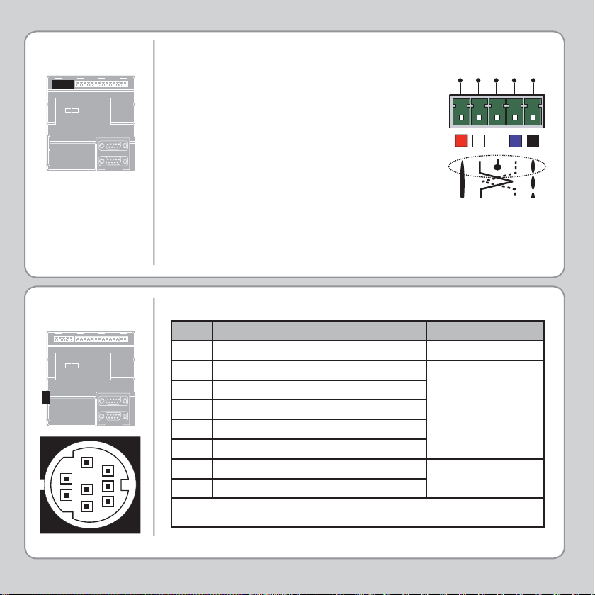
5-WAY
CONNECTOR
This is a 5 way 3.81mm pitch connector. The
connector is used both to provide the 24 Volt
power to the MC302X and provide connections
for I/O expansion via Trio’s P316 and P325 CAN
I/O expanders. A 24V dc, Class 2 transformer or
power source must be provided as this powers
the unit.
This 24 Volt input is internally isolated from the
I/O 24 Volts and the +/-10V voltage outputs.
The 24V (V+) and 0V (V-) MUST be connected
as they power the MC302X. The Shield MUST
also be connected to ground as it provides
the EMC screen for the Motion Coordinator.
The CAN connections are optional.
L
H
-
CAN
CAN
V+
SHIELD
V-
SERIAL
CONNECTIONS
5
2
4
1
3
Serial Connector A
Pin Function Note
1No Connection
2No Connection
3RS232 Transmit
4RS232 0V Serial Port #0
5RS232 Receive
6No Connection
8
7
6
7No Connection
8No Connection
Note: Port 0 is the default programming port for connection to the PC running Motion
Perfect.
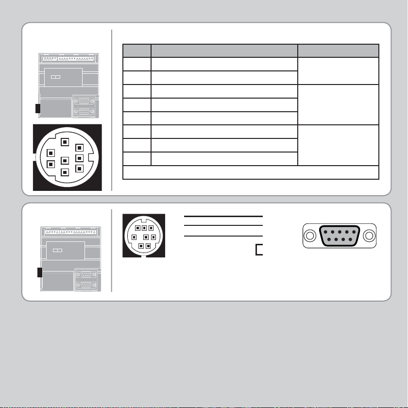
SERIAL
CONNECTIONS
5
2
4
1
3
Serial Connector B
Pin Function Note
1 RS485 Data In A Rx+
2 RS485 Data In B Rx-
Serial Port #1
3RS232 Transmit
4RS232 0V Serial Port #1
5RS232 Receive
6No Connection
8
7
6
7 RS485 Data Out Z Tx- Serial Port #1
8 RS485 Data Out Y Tx+
Note: Option for port #1 to be either RS232 or RS485
SERIAL CABLE
8
1
2
3
5
34675
4
2 - Rx
3 - Tx
5 - Gnd
7 - RTS
8 - CTS
5 4 3 2 1
9 8 7 6
Motion Coordinator to “AT” style PC with 9 pin serial connector
 Loading...