

Trio Motion Technology CAN 8 User Manual
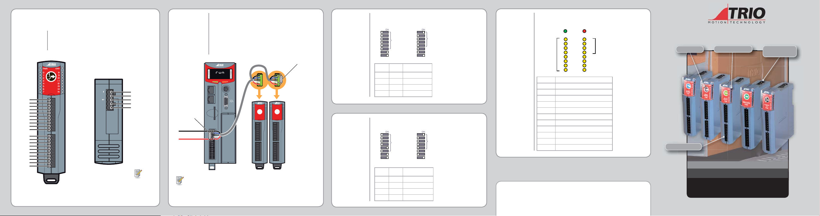
CAN 8-Relay Out Module (P327)
CONNECTIONS
Com0
NO0
NC0
Com1
NO1
NC1
Com2
NO2
Com3
NO3
Com4
NO4
NC4
Com5
NO5
NC5
Com6
NO6
Com7
NO7
Power supply: 24V dc Class 2 transfor mer or power supply. +/-20%
Max switching voltage: 30V dc, 49V ac
Absolute Max current: 1Amp
Max switching power: 62.5 VA, 24W (dc)
Isolation outputs / CA N: 1,500V dc
8-RELAY
OUT
P327
0
1
2
3
4
5
6
7
24V
0V
8
9
10
11
12
13
14
15
24V
0V
- L H +
24V DC Class 2
V- (black)
CAN_L (blue)
Shield
CAN_H (white)
V+ (red)
V+ = 24V
V- = 0V
BUS WIRING DIP SWITCH
The CAN I/O module s and the Motion Coordinator are connected
together on a C AN network. Terminate both ends of th e network
with 120Ω, 1/4W, 1% metal fi lm resistors between CA N_H and
CAN_L.
The CAN I/O module s are powered from the network. T he 24V
supply for the net work must be externally conne cted. The
Motion Coordinator does NOT prov ide the network power.
SETTINGS
P317, P318,
P319 , P327
Use recomme nded CAN bus specifi cation cables.
7HUPLQDWLQJ
Resistor
DIP SWITCH
SETTINGS
P326
MC 464
A
B
ENABLE
8
9
10
11
12
13
14
15
101011
0
1
2
3
4
5
6
7
7erPiQDtiQJ
Resistor
93oZer6XSSO\
to1etZorN
P317 / P319 - It is recommended that you use a separate p ower supply from that
used to powe r the digital out puts to power t he network a s switching noise from
the I/O devices may be car ried into the network.
Trio mode module addresses must be set in se quence wit h no
gaps starting at address 0.
Trio Mode CANopen Mode
1
2
4
Address
8
16
32
PR
(Trio Mode)
DR
N/A
1
2
4
Address
8
16
32
DR B0
PR
(CANopen Mode)
DR
DR B1
DR B1 DR B0 Data Rate Bi t/s
00125K
01250K
10500K
111M
Trio mode module addresses must be set to 16...19.
Trio Mode CANopen Mode
1
2
4
8
Address
16
32
PR
(Trio Mode)
DR
N/A
1
2
4
Address
8
16
32
DR B0
PR
(CANopen Mode)
DR
DR B1
DR B1 DR B0 Data Rate Bi t/s
00125K
01250K
10500K
111M
LED ERROR
CODES
When an erro r occurs on a C AN I/O module, the ERR LED w ill be
lit and the fault code is represented by a binar y number dis played
on the leds.
Whole Bank
Flashing
Code Error Description
1Invalid Protocol
2Invalid Module Address
3Invalid Data Rate
4 Uninitialised
5Duplicate Address
6Start Pending
7System Shutdown
8Unknown Poll
9 Poll Not Implemented
10 CAN Error
11 Receive Data Timeo ut
Trio Motion Technology Ltd.
uksales@triomotion.com
Trio Motion Technology LLC
ussales@triomotion.com
All trade mark s acknowle dged.
PWR
0
1
2
3
4
5
6
7
ERR
8
9
10
11
12
13
14
15
Tri o Sha ngh ai
chinasales@triomotion.com
Webs i te : www.t rio m ot io n . c om
Error Code
displayed on
IO 8 .. 11
Tri o Ind ia
indiasales@triomotion.com
Quick Start v 5.0 March 2011
DIP Switch
LED Indicators
Bus
Connections
I/O Connections
CAN I/O MODULES
Quick Connection Guide
(Please refer to the Motion Coordinator Technical Referen ce Manual 7 for Full Detail s)
DESCRIPTION
IMPORTANT
Trio CAN Input an d CAN Outp ut modules allow I/O expansion
for the MC46 4 and for most of the range of MC2 xx and MC3xx
Motion Coordinators. The number of CA N Input and CA N
Output modules that can be connected to a sin gle network
depends o n which master is u sed.
MC464 MASTER
Up to 16 CAN 16-Outp ut modules an d up to 16 CAN 16-Input
modules may be connected allowing 512 channels in addition to
the internal chann els built-in to the Motion Coordinator.
P319 Input / Output Mod ule counts as 1 Input Module + 1
Output Module.
P327 8 Relay Module co unts as 1 Output Module
Requires system software V 2.0098 or above.
MC2XX / MC3XX MASTER OR MC464 WITH P3 15/
P316 ON THE CANBUS
CAN 16-Output modules and CAN 16-Input modules may be mi xed
with CAN 16-I/O module s up to a total of 16 modules allowing up
to 256 input/output channels in addition to the internal channels
built-in to the Motion Coordinator.
Up to 4 CAN Analogue I/O modules may be connected, allowing
up to 32 analogue inp ut channels an d up to 16 analogue output
channels.
Analogue out put channels can be used v ia the AOUT(n) command
or CAN comm and depending on the Motion Coordinator and
system software version.
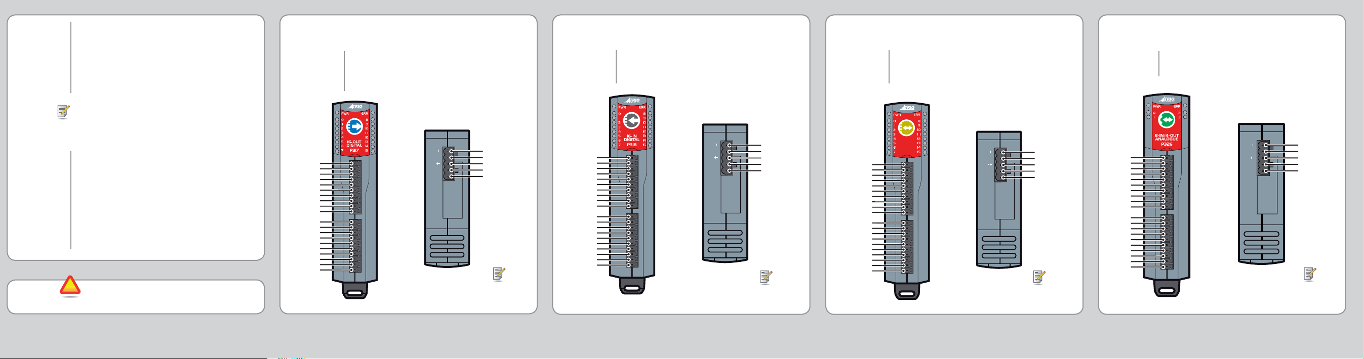
!
Upon deliver y, all CAN Module s are set in Trio mode. To
switch to CANopen m ode see the DIP switch settings sec tion.
CAN 16-Output Module (P317)
CONNECTIONS
0 Out
1 Out
2 Out
3 Out
4 Out
5 Out
6 Out
7 Out
24V
0V
8 Out
9 Out
10 Out
11 Out
12 Out
13 Out
14 Out
15 Out
24V
0V
Power supply: 24V dc Class 2 transfor mer or power supply. +/-20%
Output bank 1: 8 x 24V dc 250 mA outputs. 24V supply
Output bank 2: 8 x 24V dc 250 mA outp uts. 24V supply
Max curre nt per output b ank: 1A
Isolation b etween output banks: 1,500 V dc
Isolation b etween out puts/CAN: 1,500V dc
- L H +
24V DC Class 2
0
1
2
3
4
5
6
7
24V
0V
8
9
10
11
12
13
14
15
24V
0V
V- (black)
CAN_L (blue)
Shield
CAN_H (white)
V+ (red)
V+ = 24V
V- = 0V
CAN 16-Input Module (P318)
CONNECTIONS
0 In
1 In
2 In
3 In
4 In
5 In
6 In
7 In
N/C
0V
8 In
9 In
10 In
11 In
12 In
13 In
14 In
15 In
N/C
0V
Power supply: 24V dc Class 2 transfor mer or power supply. +/-20%
Input bank 1: 8 x 24V dc input s. 0V common
Input bank 2: 8 x 24V dc i nputs. 0V common
Isolation b etween input banks: 1,500V dc
Isolation between inputs/CAN: 1,500V dc
24V DC Class 2
0
1
2
3
4
5
6
7
24V
0V
8
9
10
11
12
13
14
15
24V
0V
- L H +
V- (black)
CAN_L (blue)
Shield
CAN_H (white)
V+ (red)
V+ = 24V
V- = 0V
CAN 16-Input / Output Module (P319 )
CONNECTIONS
0 I/O
1 I/O
2 I/O
3 I/O
4 I/O
5 I/O
6 I/O
7 I/O
24V
8 I/O
9 I/O
10 I/O
11 I/O
12 I/O
13 I/O
14 I/O
15 I/O
24V
Power supply: 24V dc Class 2 transfor mer or power supply. +/-20%
Bank 1: 8 x 24V dc inputs / 25 0mA outp uts
Bank 2: 8 x 24V dc inputs / 250mA o utputs
Max curre nt per output b ank: 1 Amp
Isolation b etween I/O banks: 1,500V dc
Isolation between inputs/CAN: 1,500V dc
16-I/O
DIGITAL
P319
0
1
2
3
4
5
6
7
24V
0V
0V
0V
8
9
10
11
12
13
14
15
24V
0V
- L H +
24V DC Class 2
V- (black)
CAN_L (blue)
Shield
CAN_H (white)
V+ (red)
V+ = 24V
V- = 0V
CAN Analogue I/O Module (P326)
CONNECTIONS
0 Ain
1 Ain
2 Ain
3 Ain
4 Ain
5 Ain
6 Ain
7 Ain
N/C
0V
0 Vout
0V
1 Vout
0V
2 Vout
0V
3 Vout
0V
N/C
0V
Power supply: 24V dc Class 2 transfor mer or power supply. +/-20%
Analogue inp uts: 8 x 12 bit, +/-10V, single ende d, 0V common
Analogue outputs: 4 x 12 bit, +/-10V, single ended, 0V common
I/O is isolated from CAN bus.
- L H +
24V DC Class 2
0
1
2
3
4
5
6
7
24V
0V
8
9
10
11
12
13
14
15
24V
0V
V- (black)
CAN_L (blue)
Shield
CAN_H (white)
V+ (red)
V+ = 24V
V- = 0V
 Loading...