


GL700 Series
Laser Transmitter
User Guide
F
Version 3.75
Revision C
Part Number 1445-0100
September 2007

Corporate Office
Trimble Construction Division
5475 Kellenburger Road
Dayton, Ohio 45424-1099
U.S.A.
Copyright and Trademarks
Copyright © 2002–2007, Trimble Navigation Limited. All
rights reserved.
Trimble, and the Globe & Triangle logo are trademarks of
Trimble Navigation Limited, registered in the United
States Patent and Trademark Office. Spectra Precision is a
trademark of Trimble Navigation Limited. All other
trademarks are the property of their respective owners.
Release Notice
This is the September 2007 release (Revision C) of the
GL700 Series Laser Transmitter User Guide, part number
1445-0100. It applies to version 3.75 of the GL700 Series
Laser Transmitter.
The following limited warranties give you specific legal
rights. You may have others, which vary from
state/jurisdiction to state/jurisdiction.
Hardware Limited Warranty
Trimble Navigation Limited warrants that this hardware
product (the “Product”) will perform substantially in
accordance with published specifications and be
substantially free of defects in material and workmanship
for a period of two (2) years starting from the date of
delivery. The warranty set forth in this paragraph shall not
apply to software products.
Software License, Limited Warranty
This Trimble software product, whether provided as a
stand-alone computer software product, built into
hardware circuitry as firmware, embedded in flash
memory, or stored on magnetic or other media, (the
“Software”) is licensed and not sold, and its use is
governed by the terms of the relevant End User License
Agreement (“EULA”) included with the Software. In the
absence of a separate EULA included with the Software
providing different limited warranty terms, exclusions and
limitations, the following terms and conditions shall apply.
Trimble warrants that this Trimble Software product will
substantially conform to Trimble’s applicable published
specifications for the Software for a period of ninety (90)
days, starting from the date of delivery.
Warranty Remedies
Trimble's sole liability and your exclusive remedy under
the warranties set forth above shall be, at Trimble’s option,
to repair or replace any Product or Software that fails to
conform to such warranty ("Nonconforming Product") or
refund the purchase price paid by you for any such
Nonconforming Product, upon your return of any
Nonconforming Product to Trimble in accordance with
Trimble’s standard return material authorization
procedures.
Warranty Exclusions and Disclaimer
These warranties shall be applied only in the event and to
the extent that (i) the Products and Software are properly
and correctly installed, configured, interfaced, maintained,
stored, and operated in accordance with Trimble's relevant
operator's manual and specifications, and; (ii) the Products
and Software are not modified or misused. The preceding
warranties shall not apply to, and Trimble shall not be
responsible for defects or performance problems resulting
from (i) the combination or utilization of the Product or
Software with hardware or software products, information,
data, systems, interfaces or devices not made, supplied or
specified by Trimble; (ii) the operation of the Product or
Software under any specification other than, or in addition
to, Trimble's standard specifications for its products; (iii)
the unauthorized modification or use of the Product or
Software; (iv) damage caused by accident, lightning or
other electrical discharge, fresh or salt water immersion or
spray; or (v) normal wear and tear on consumable parts
(e.g., batteries). Trimble does not warrant or guarantee the
results obtained through the use of the Product.
THE WARRANTIES ABOVE STATE TRIMBLE'S ENTIRE
LIABILITY, AND YOUR EXCLUSIVE REMEDIES,
RELATING TO PERFORMANCE OF THE PRODUCTS AND
SOFTWARE. EXCEPT AS OTHERWISE EXPRESSLY
PROVIDED HEREIN, THE PRODUCTS, SOFTWARE, AND
ACCOMPANYING DOCUMENTATION AND MATERIALS
ARE PROVIDED “AS-IS” AND WITHOUT EXPRESS OR
IMPLIED WARRANTY OF ANY KIND BY EITHER
TRIMBLE NAVIGATION LIMITED OR ANYONE WHO
HAS BEEN INVOLVED IN ITS CREATION, PRODUCTION,
INSTALLATION, OR DISTRIBUTION INCLUDING, BUT
NOT LIMITED TO, THE IMPLIED WARRANTIES OF
MERCHANTABILITY AND FITNESS FOR A PARTICULAR
PURPOSE, TITLE, AND NONINFRINGEMENT. THE
STATED EXPRESS WARRANTIES ARE IN LIEU OF ALL
OBLIGATIONS OR LIABILITIES ON THE PART OF
TRIMBLE ARISING OUT OF, OR IN CONNECTION WITH,
ANY PRODUCTS OR SOFTWARE. SOME STATES AND
JURISDICTIONS DO NOT ALLOW LIMITATIONS ON
DURATION OR THE EXCLUSION OF AN IMPLIED
WARRANTY, SO THE ABOVE LIMITATION MAY NOT
APPLY TO YOU.
TRIMBLE NAVIGATION LIMITED IS NOT
RESPONSIBLE FOR THE OPERATION OR FAILURE
OF OPERATION OF GPS SATELLITES OR THE
AVAILABILITY OF GPS SATELLITE SIGNALS.
Limitation of Liability
TRIMBLE’S ENTIRE LIABILITY UNDER ANY PROVISION
HEREIN SHALL BE LIMITED TO THE AMOUNT PAID BY
YOU FOR THE PRODUCT OR SOFTWARE LICENSE. TO
THE MAXIMUM EXTENT PERMITTED BY APPLICABLE
LAW, IN NO EVENT SHALL TRIMBLE OR ITS SUPPLIERS
BE LIABLE FOR ANY INDIRECT, SPECIAL, INCIDENTAL
OR CONSEQUENTIAL DAMAGES WHATSOEVER UNDER
ANY CIRCUMSTANCE OR LEGAL THEORY RELATING
IN ANY WAY TO THE PRODUCTS, SOFTWARE AND
ACCOMPANYING DOCUMENTATION AND MATERIALS,
(INCLUDING, WITHOUT LIMITATION, DAMAGES FOR
LOSS OF BUSINESS PROFITS, BUSINESS
INTERRUPTION, LOSS OF BUSINESS INFORMATION, OR
ANY OTHER PECUNIARY LOSS), REGARDLESS
WHETHER TRIMBLE HAS BEEN ADVISED OF THE
POSSIBILITY OF ANY SUCH LOSS AND REGARDLESS OF
THE COURSE OF DEALING WHICH DEVELOPS OR HAS
DEVELOPED BETWEEN YOU AND TRIMBLE. BECAUSE
SOME STATES AND JURISDICTIONS DO NOT ALLOW
THE EXCLUSION OR LIMITATION OF LIABILITY FOR
CONSEQUENTIAL OR INCIDENTAL DAMAGES, THE
ABOVE LIMITATION MAY NOT APPLY TO YOU.

NOT WITHSTANDING THE ABOVE, IF YOU PURCHASED
THIS PRODUCT OR SOFTWARE IN THE EUROPEAN
UNION, THE ABOVE WARRANTY PROVISIONS MAY
NOT APPLY. PLEASE CONTACT YOUR DEALER FOR
APPLICABLE WARRANTY INFORMATION.
Notices
Class B Statement – Notice to Users. This equipment has
been tested and found to comply with the limits for a Class
B digital device, pursuant to Part 15 of the FCC rules.
These limits are designed to provide reasonable protection
against harmful interference in a residential installation.
This equipment generates, uses, and can radiate radio
frequency energy and, if not installed and used in
accordance with the instructions, may cause harmful
interference to radio communication. However, there is no
guarantee that interference will not occur in a particular
installation. If this equipment does cause harmful
interference to radio or television reception, which can be
determined by turning the equipment off and on, the user is
encouraged to try to correct the interference by one or more
of the following measures:
– Reorient or relocate the receiving antenna.
– Increase the separation between the equipment and the
receiver.
– Connect the equipment into an outlet on a circuit
different from that to which the receiver is connected.
– Consult the dealer or an experienced radio/TV
technician for help.
Changes and modifications not expressly approved by the
manufacturer or registrant of this equipment can void your
authority to operate this equipment under Federal
Communications Commission rules.
Special precautions have been taken to ensure the
calibration of the laser; however, calibration is not covered
by this warranty. Maintenance of the calibration is the
responsibility of the user.
The foregoing states the entire liability of Trimble
regarding the purchase and use of its equipment. Trimble
will not be held responsible for any consequential loss or
damage of any kind.
This warranty is in lieu of all other warranties, except as set
forth above, including an implied warranty mechantability
of fitness for a particular purpose, are hereby disclaimed.
Notice to Our European Union Customers
For product recycling instructions and more information,
please go to:
To recycle Trimble WEEE,
call: +31 497 53 2430, and
ask for the "WEEE associate," or
mail a request for recycling instructions to:
Trimble Europe BV
c/o Menlo Worldwide Logistics
Meerheide 45
5521 DZ Eersel, NL
www.trimble.com/environment/summary.html
Recycling in Europe
Warranty
Trimble warrants the GL700 series lasers, radio remote
control, and receiver to be free of defects in material and
workmanship for a period of two years. This warranty
period is in effect from the date the system is delivered by
Trimble or its authorized Dealer to the purchaser, or is put
into service by a Dealer as a demonstrator or rental
components.
Additionally, items covered by the standard Trimble oneyear warranty are the accessories. All other components
not manufactured by Trimble but sold as a part of the
system such as tripods and grade rods, will carry a 90-day
warranty or the manufacturer’s warranty, whichever is
greater.
Trimble or its Authorized Service Center will repair or
replace, at its option, any defective part of components of
which notice has been given during the warranty period. A
Warranty Registration Card must be filled out properly and
on file with Trimble Service Department before warranty
repair or replacement can be approved. Travel and per diem
expenses, if required, to and from the place where repairs
are made will be charged to the purchaser at the prevailing
rates.
Customers should send products to the nearest Authorized
Factory Service Center for warranty repairs, freight
prepaid. In countries with Trimble Subsidiary Service
Centers, the repaired products will be returned to the
customer, freight prepaid.
Any evidence of negligent, abnormal use, accident, or any
attempt to repair equipment by other than factoryauthorized personnel using Trimble certified or
recommended parts, automatically voids the warranty.

EMC Declaration of Conformity 10.1
This laser has been tested and found to comply with the limits for a Class B digital device for
radio noise for digital apparatus set out in the Radio Interference Regulations of the
Canadian Department of Communication, and is pursuant to part 15 of the Federal
Communication Commission (FCC) rules. These limits are designed to provide reasonable
protection against harmful interference in a residential installation. This laser generates
radio frequency. If it is not used in accordance with the instructions, it may cause harmful
interference to radio or television reception. Such interference can be determined by turning
the laser off and on. You are encouraged to try eliminating the interference by one or more of
the following measures:
• Reorient or relocate the receiving antenna.
• Increase the separation between the laser and the receiver.
For more information, consult your dealer or an experienced radio/television technician.
Caution – Changes or modifications to the laser that are not expressly approved by
C
Application of Council Directive(s): 1995/5/EC and 1973/23/EEC
Manufacturer's Name: Trimble
Manufacturer's Address: 5475 Kellenburger Road
European Representative Address: Trimble GmbH
Model Number(s): GL710, 720, 722, and 742
Conformance to Directive(s): 1999/5/EC using EN300386:1994,
Equipment Type/Environment: ITE/residential, commercial and light
Product Standards: EN300386:1994, EN300328:1996,
Trimble could void authority to use the equipment.
Dayton, Ohio 45424-1099
U.S.A.
Am Prime Parc 11
65479 Raunheim, Germany
EN300328:1996, EN61000-6-2:1999, and
EN61010-1:2001;
1973/23/EEC using EN60825-1-A2:2001 and
EN60825-1-A11:1996.
industrial
EN61000-6-2:1999, EN61010-1:2001,
EN60825-1-A2:2001, EN60825-1-A11:1996.

Safety Information
The IEC and the United States Government Center of Devices for Radiology Health (CDRH)
has classified these laser as Class 2 (658 nm, visible beam on standard models), and Class 1
(785 nm, infrared beam on IR models) laser products.
Operation 1.1
For detailed installation and operating instructions, follow the instructions given in this
manual for this laser. The maximum radiant power output of this laser is less than 5 mW.
Controls 1.2
Controls are listed in the operation section of this manual.
Caution – Use of controls or adjustments performance of procedures other
C
than those specified herein may result in higher dosage of laser exposure.
This laser complies with all applicable portions of CDRH 21 CFR 1040.10 and 1040.11 of the
code of Federal Regulations, Department of Health and Human Services, Food and Drug
Administration (Federal Register, Volume 50, Number 161, August 20, 1985).
Protective eyewear 1.3
This laser complies with OSHA Standards Act Section 1518.54 for use without eye protection
devices. Consequently, protective eyewear is neither required nor recommended. As with any
visible laser device, the following safety rules should be observed:
• Never look directly into a laser beam or point the beam into the eyes of others. Set the
laser at a height that prevents the beam from shining directly into people's eyes.
• Do not remove any warning signs from the laser.
• Use of this product by people other than those trained on this product may result in
exposure to hazardous laser light.
• If initial service is required, which results in the removal of the outer protective cover,
removal must only be performed by factory-trained personnel.
GL700 Series Laser Transmitter User Guide v
Safety Information
Cautions and Notes 13.1
Included in this manual are CAUTIONS and Notes. Each of these words represents a level of
danger or concern.
A CAUTION indicates a hazard or an unsafe practice that could result in minor injury or
property damage.
A Note indicates important information unrelated to safety.
Questions about laser safety should be addressed to:
Trimble Construction Division
5475 Kellenburger Road
Dayton, Ohio 45424-1099 U.S.A.
Attention: Quality Assurance Group, Laser Safety Officer
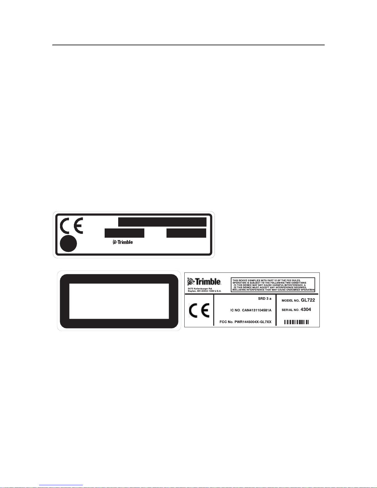
Labels required for this product
MFG.
MODEL:
COMPLIES WITH
21 CFR 1040 AS
APPLICABLE
✔
S/N
N324
DO NOT STARE INTO BEAM
CLASS 2 LASER PRODUCT
TRIMBLE ENGINEERING AND
CONTRUCTION DIVISION
LASER RADIATION
This ISM device complies with Canadian ICES-001.
Cet appareil ISM est conforme a_ la norme NMB-001 du Canada.
This device is intended to be used in the following Member States: Belgium, Germany,
France, Italy, Luxembourg, the Netherlands, Denmark, Ireland, the United Kingdom, Greece,
Spain, Portugal, Austria, Finland and Sweden. The alert symbol on the CE label indicates that
while this device is declared compliant with relevant EU requirements, some geographical
restrictions apply in France. Regulations are in a state of flux and the user is urged to contact
local French authorities for details.
This device is a “Class 2” radio device in all member States.
vi GL700 Series Laser Transmitter User Guide

Contents
Safety Information
Operation . . . . . . . . . . . . . . . . . . . . . . . . . . . . . v
Controls. . . . . . . . . . . . . . . . . . . . . . . . . . . . . . v
Protective eyewear . . . . . . . . . . . . . . . . . . . . . . . . . v
Cautions and Notes . . . . . . . . . . . . . . . . . vi
1 Introduction
Claim for Damage in Shipment . . . . . . . . . . . . . . . . . . . 2
Owner’s Record . . . . . . . . . . . . . . . . . . . . . . . . . . 2
2 Features and Functions
Laser . . . . . . . . . . . . . . . . . . . . . . . . . . . . . . . 3
Two-Way Radio Remote Control
(Radio equipped lasers only) . . . . . . . . . . . . . . . . . . . . 6
Accessories . . . . . . . . . . . . . . . . . . . . . . . . . . . . 8
Connector cable . . . . . . . . . . . . . . . . . . .8
Remote holster . . . . . . . . . . . . . . . . . . . .9
Battery recharger . . . . . . . . . . . . . . . . . . .9
M100 3½
M102 Quick-disconnect adapter . . . . . . . . . . . . 10
M103 Steep-grade adapter . . . . . . . . . . . . . . 10
1243 Sighting scope (GL710 and GL720 only) . . . . . . 10
External power cable. . . . . . . . . . . . . . . . . 10
-8 Adapter . . . . . . . . . . . . . . . . . 10
3 How to Use the Laser System
Powering the Laser – Batteries . . . . . . . . . . . . . . . . . . .11
Recharging the batteries. . . . . . . . . . . . . . . . 12
Installing/removing the batteries . . . . . . . . . . . . 13
Powering the Laser – External Cable. . . . . . . . . . . . . . . . .14
Connecting/disconnecting the external power cable. . . . . 14
Learning the Basic Laser Functions . . . . . . . . . . . . . . . . .15
Turning on/off the laser . . . . . . . . . . . . . . . . 15
Selecting the rotation speed . . . . . . . . . . . . . . 16
GL700 Series Laser Transmitter User Guide vii

Contents
Changing the grade value . . . . . . . . . . . . . . . 16
Activating/deactivating manual mode . . . . . . . . . . 17
Rotating the axis alignment manually . . . . . . . . . . 17
Two-Way Radio Remote Control
(Radio equipped lasers only) . . . . . . . . . . . . . . . . . . . 18
Installing/removing the radio remote control batteries . . . . 18
Learning basic radio remote control functions . . . . . . . 20
4 System Setup
General Setup Information . . . . . . . . . . . . . . . . . . . . 27
Getting Connected . . . . . . . . . . . . . . . . . . . . . . . . 28
Laser . . . . . . . . . . . . . . . . . . . . . . . 28
Radio remote control . . . . . . . . . . . . . . . . . 30
Setting Up the Laser System . . . . . . . . . . . . . . . . . . . 31
Setting up the laser in manual mode . . . . . . . . . . . 31
Aligning the axis manually . . . . . . . . . . . . . . 32
Setting up the laser in vertical mode . . . . . . . . . . . 33
Establishing Control . . . . . . . . . . . . . . . . . . . . . . . 33
Determining height of instrument (HI) . . . . . . . . . . 33
Establishing elevation-control hubs . . . . . . . . . . . 34
Establishing grade-control hubs . . . . . . . . . . . . 34
Reversing the Grade
(Two-way radio remote control) . . . . . . . . . . . . . . . . . . 35
5 Automatic Alignment Modes
Summary . . . . . . . . . . . . . . . . . . . . . . . . . . . . 37
Automatic axis alignment mode . . . . . . . . . . . . 37
Grade-matching mode . . . . . . . . . . . . . . . . 38
PlaneLok mode . . . . . . . . . . . . . . . . . . . 38
Using Axis-Alignment and Grade-Reverse Modes . . . . . . . . . . 39
How axis-alignment mode works . . . . . . . . . . . . 39
Important things to know . . . . . . . . . . . . . . . 39
Applications . . . . . . . . . . . . . . . . . . . . 40
Using Grade-Matching Mode . . . . . . . . . . . . . . . . . . . 45
How grade-matching mode works . . . . . . . . . . . . 45
Important things to know . . . . . . . . . . . . . . . 45
Application . . . . . . . . . . . . . . . . . . . . 46
viii GL700 Series Laser Transmitter User Guide

Using PlaneLok Mode . . . . . . . . . . . . . . . . . . . . . . 49
How PlaneLok mode works . . . . . . . . . . . . . . 49
Important things to know . . . . . . . . . . . . . . . 49
Applications . . . . . . . . . . . . . . . . . . . . 50
Using the Radio Remote Control to Correct Grade/Height Differences
After Setup . . . . . . . . . . . . . . . . . . . . . . . . . . . 52
Two-way radio remote control . . . . . . . . . . . . . 52
6 Specifications
Laser . . . . . . . . . . . . . . . . . . . . . . . . . . . . . . 53
Two-way Radio Remote Control. . . . . . . . . . . . . . . . . . 55
7 Maintenance and Care
Introduction . . . . . . . . . . . . . . . . . . . . . . . . . . . 57
Storage . . . . . . . . . . . . . . . . . . . . . . . . . . . . . 57
Battery Disposal . . . . . . . . . . . . . . . . . . . . . . . . . 57
System Cleaning . . . . . . . . . . . . . . . . . . . . . . . . . 57
Contents
8 Troubleshooting
Introduction . . . . . . . . . . . . . . . . . . . . . . . . . . . 59
Laser . . . . . . . . . . . . . . . . . . . . . . . . . . . . . . 60
Receiver. . . . . . . . . . . . . . . . . . . . . . . . . . . . . 61
Radio Remote Control . . . . . . . . . . . . . . . . . . . . . . 62
Messages . . . . . . . . . . . . . . . . . . . . . . . . . . . . 63
Radio remote control messages. . . . . . . . . . . . . 63
Laser error messages . . . . . . . . . . . . . . . . . 67
9 Calibration
Introduction . . . . . . . . . . . . . . . . . . . . . . . . . . . 69
Checking Calibration . . . . . . . . . . . . . . . . . . . . . . . 70
Adjusting the Calibration at the Laser . . . . . . . . . . . . . . . 72
Adjusting the Calibration Using the Radio Remote Control. . . . . . 74
10 Request for Service and Parts
Trimble Service Centers . . . . . . . . . . . . . . . . . . . . . 77
Checklist . . . . . . . . . . . . . . . . . . . . . . . . . . . . 78
GL700 Series Laser Transmitter User Guide ix

Contents
x GL700 Series Laser Transmitter User Guide

CHAPTER
Introduction 1
1
Thank you for choosing one of the Spectra Precision™ Lasers from the Trimble®
family of precision grade lasers. You’ve just made a wise investment in field-proven
products made by Trimble, the world’s largest manufacturer of laser-based leveling,
alignment, and grade-control systems.
The grade laser is an easy-to-use tool that allows you to take accurate horizontal
measurements with grade up to 750 m (2500 ft) away using a receiver. The
exclusive automatic alignment features allow for quick and easy setup. The
exclusive temperature and grade compensation systems are designed for superior
accuracy so that your grade laser can be used for machine-control, general
construction, and surveying applications requiring tight tolerances under all
environmental conditions.
Included in this manual is information about setting up, using, maintaining, and
troubleshooting the laser system. Use the manual now to learn basic skills, and use
it later for reference. For the best performance of your laser system, follow the
maintenance and care recommendations in this manual. Be sure to keep this manual
in a convenient place for easy referencing.
Your comments and suggestions are welcome; please call the Trimble Construction
Division listed below for your local, authorized Trimble office.
Trimble Construction Division
5475 Kellenburger Road
Dayton, Ohio 45424-1099 U.S.A.
(800) 538-7800 (Toll free in U.S.A.)
+1-937-245-5600 Phone
+1-937-233-9004 Fax
www.trimble.com
GL700 Series Laser Transmitter User Guide 1

1 Introduction
Claim for Damage in Shipment 1.1
The grade laser system generally includes a laser, remote control, receiver, generalpurpose clamp, operator’s manual, laser safety kit, carrying case, rechargeable
batteries, and battery recharger. The components vary depending on the system that
you purchase.
You should inspect your laser system as soon as you receive it. It has been packaged
for safe delivery. If it is damaged in any way, immediately file a claim with the
carrier or, if insured separately, with the insurance company.
Owner’s Record 1.2
Be sure to record the serial number of each component in the space provided below.
Refer to these numbers if you need to contact your Trimble dealer regarding any of
these products.
Model #_____________________________________
Serial #_____________________________________
2 GL700 Series Laser Transmitter User Guide
CHAPTER
Features and
Functions 2
2
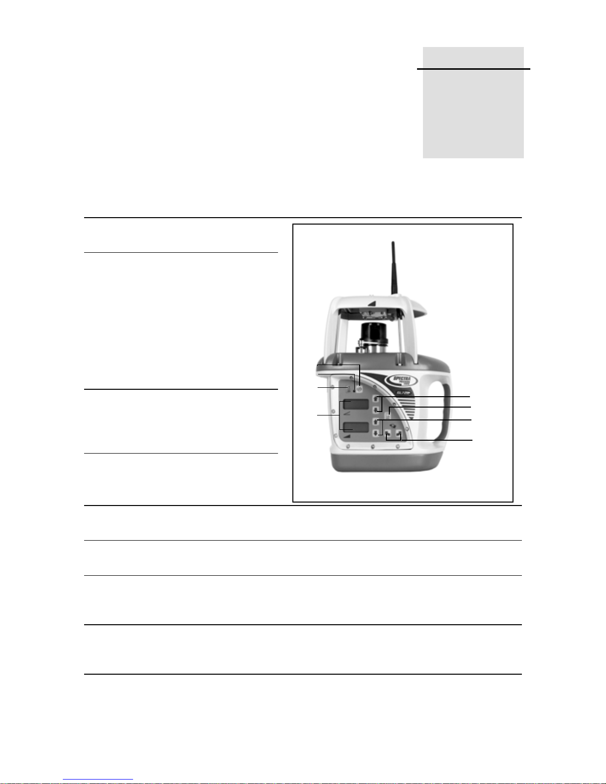
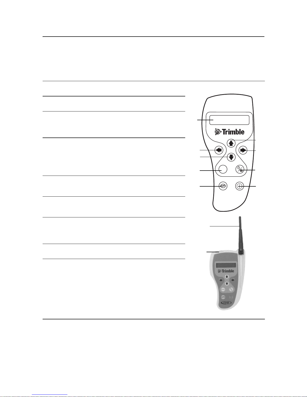
Laser 2.1
1 Power button (π) – turns the
laser on/off.
2 Status LED – shows the
status of various conditions
including an internal,
electronic, or a mechanical
error (solid red), low-battery
(flashing yellow), manual
mode (flashing red), HI alert
(fast flashing red), and out-oflevel (flashing green).
3 Manual button (
the laser from automatic selfleveling
to manual mode.
μ) – changes
3
2
1
4
8
5
6
7
4
1 Axis Up (υ) and Down
(
δ) buttons – change the
grade for the
5 Rotation-Control button (
600, and 900 rpm).
6
2 Axis Up (υ) and Down (δ) buttons (dual-grade laser only) – change the
grade for the
7 Axis-Alignment buttons – rotates the grade axis clockwise (
counterclockwise (
its tripod, with fine adjustment capability.
8 Liquid Crystal Displays (LCDs) – show the percentage of grade, approximate
charge of the batteries, beam’s rotation speed, and axis alignment (if other
than zero). The single-grade laser has one LCD.
1 axis.
ρ) – changes the laser beam’s rotation speed (300,
2 axis.
Λ) or
Ρ). Rotating the grade axis simulates turning the laser on
GL700 Series Laser Transmitter User Guide 3
2 Features and Functions
9
10
11
12
13
14
15
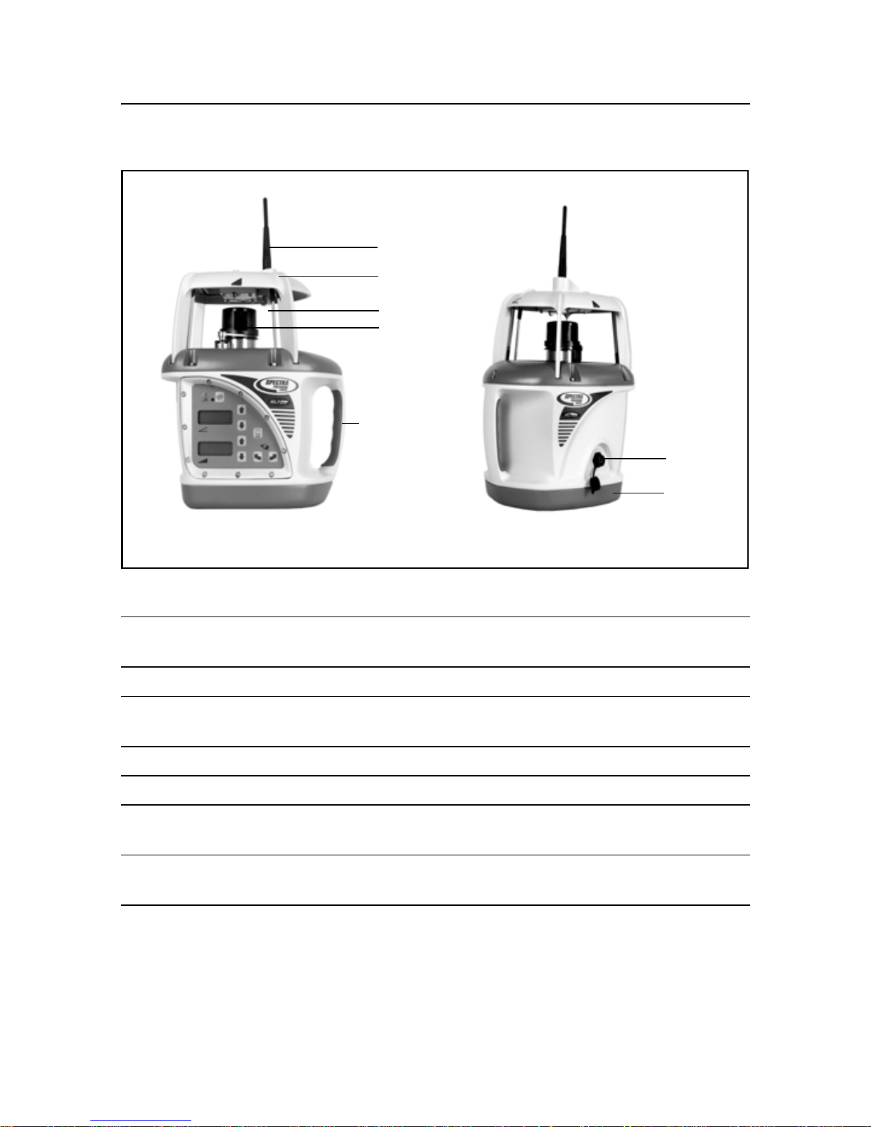
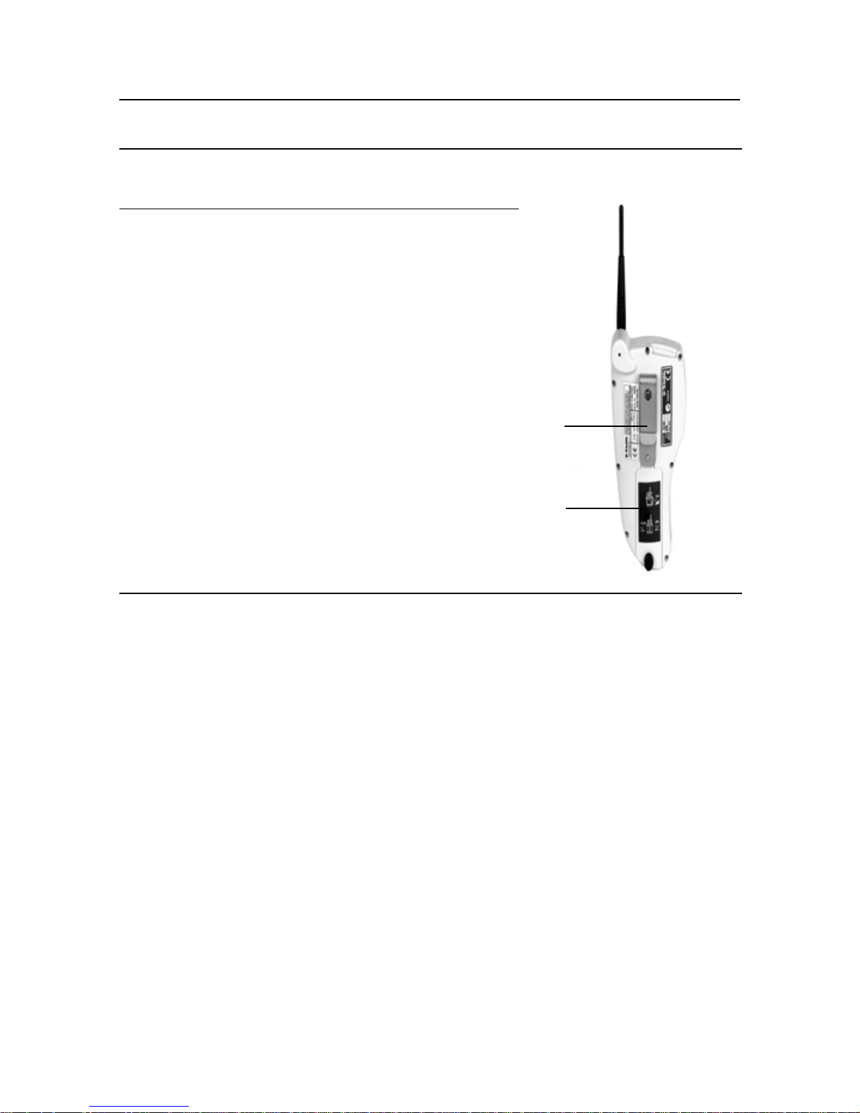
Figure 2.1 Laser transmitter – front and back
9 Antenna (for radio remote-control lasers only) – sends and receives signals
to and from the remote control.
10 Sunshade – protects the lighthouse from the environment.
11 Lighthouse – is the 360° exit window for the laser beam. The lighthouse is
sealed and protects the internal components from the environment.
12 Rotor – contains the rotating laser beam.
13 Handle – allows you to carry the laser easily.
14 Battery Recharging Receptacle – is the 4-pin receptacle that the battery
recharger plugs into. It is also used for external power.
15 Battery Housing – holds six D-cell Ni-Cd, Ni-MH, or backup alkaline
batteries.
4 GL700 Series Laser Transmitter User Guide
17
16
18
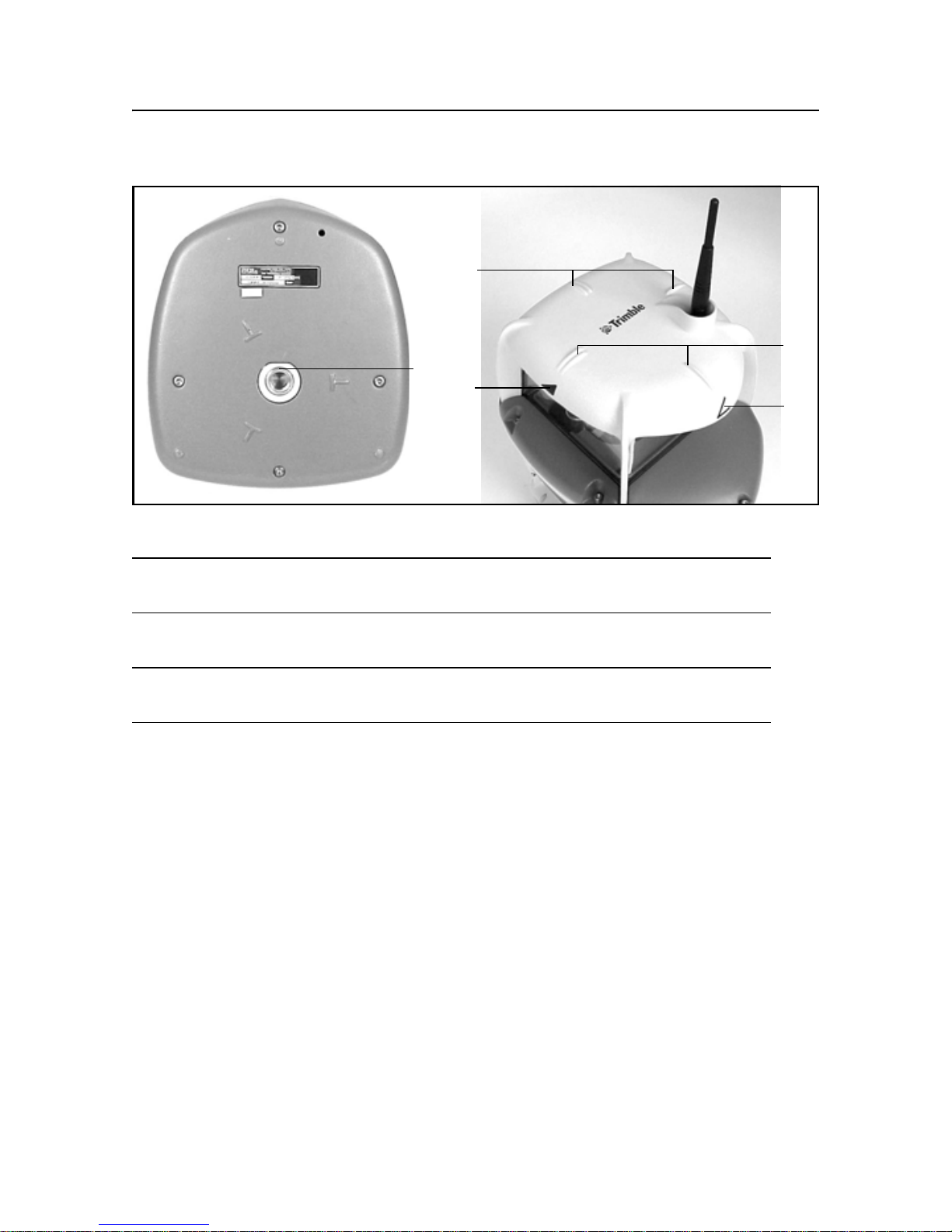
Figure 2.2 Laser transmitter – base and top
Features and Functions 2
17
18
16 5/8-11 Tripod Mount – allows the laser to be connected to a standard
5/8-11 tripod or column mount.
17 Sighting Guides – are used to visually align the laser with a directional
hub or grade stake.
18 Axis-Alignment Marks – correspond with both laser axes and are used
to align the laser in the correct grade direction.
GL700 Series Laser Transmitter User Guide
5
2 Features and Functions
Two-Way Radio Remote Control
(Radio equipped lasers only) 2.2
1
2
3
4
5
6
7
Power/Standby button (π) – turns the remote control
on/off and activates/deactivates standby mode.
Manual button (μ) – changes the laser from
automatic self-leveling to manual mode.
Mode button (Μ) – allows you to choose the laser’s
operational mode, which includes grade change,
automatic axis alignment, grade matching, PlaneLok,
grade reverse, and beam rotation speed.
Up (υ) and Down (δ) buttons – increase/decrease
the grade for the
increase/decrease the laser beam’s rotation speed.
When the laser is in manual mode, these buttons can
also be used to increase/decrease the slope of the
laser beam.
Left (ν) and Right (σ) buttons – increase/decrease
the slope of the
mode.
Liquid Crystal Display (LCD) – shows the mode
messages, beam’s rotation speed, and percentage of
grade.
Enter/Backlight button (ε) – is a multifunctional
button that confirms the selection made from the
laser’s operational mode and activates the
backlighting function.
1 and 2 axes and
2 axis when the laser is in manual
6
4
5
4
3
2
8
MODE
5
7
1
8
9
Antenna – transfers signals between the radio remote
control and laser.
Remote port contacts – transfer operation and
elevation information between the remote control and
the receiver.
6 GL700 Series Laser Transmitter User Guide
9
10 Mounting clip – allows the remote control to be
connected to a grade-rod holster, belt, or a screw on
a wall.
Features and Functions 2
11 Battery Housing
– holds two AA alkaline batteries.
10
11
GL700 Series Laser Transmitter User Guide
7
2 Features and Functions
Accessories 2.3
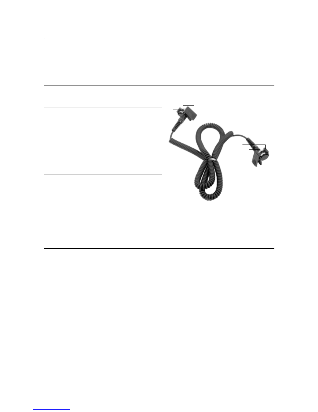
Connector cable 23.1
1 Mounting guides – fit into the mounting
channels on the receiver or the radio
remote control.
2 Contacts – transfer grade-display
signals between the hand-held receiver
and radio remote control.
3 Clamp – connects to the receiver so
signals can be transferred between the
receiver and the radio remote control.
4 4 m (12-ft) cable – transfers signals
between the radio remote control and a
hand-held receiver.
5 Clamp – connects to the radio remote
control so signals can be transferred
between the receiver and the radio
remote control.
To install:
1. Put the small key of the clamp into
the guide on the back of the radio
remote control.
2. Clip the top part of the clamp into the
guide on the front of the radio remote
control.
1
2
3
4
1
2
5
8 GL700 Series Laser Transmitter User Guide
Features and Functions 2
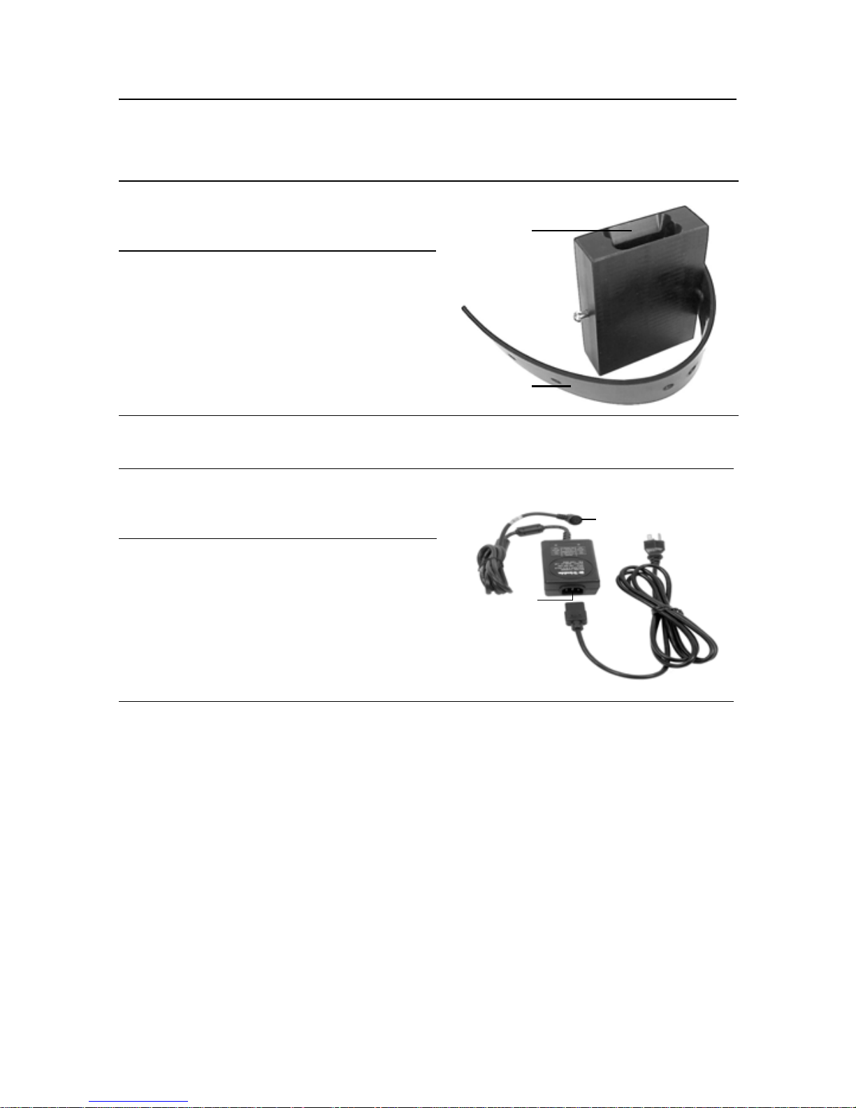
Remote holster 20.1
1 Mounting slot – provides an
opening for the radio remote
control clip to be slipped into.
1
2 Mounting strap – allows the radio
remote control to be connected to
the grade rod for automatic
alignment functions. The holes in
the strap accommodate grade
rods of varying sizes.
2
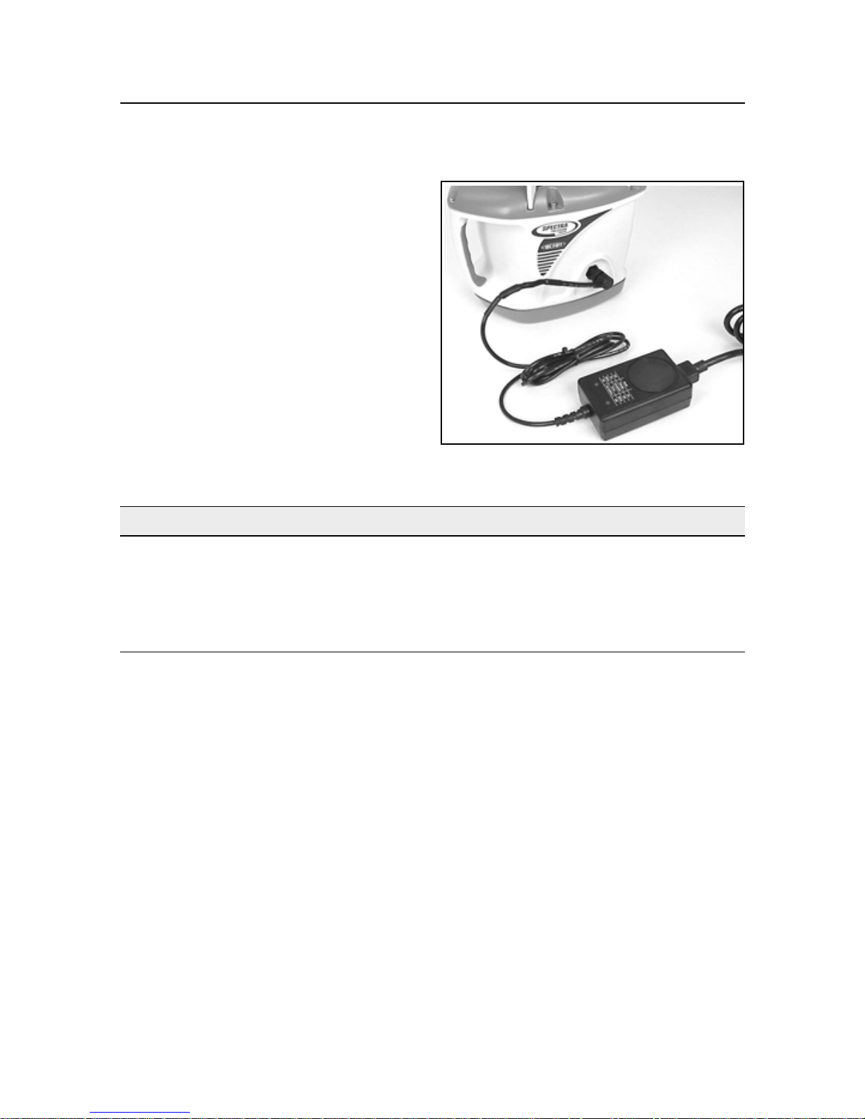
Battery recharger 20.2
1 4-socket plug with retaining collar
– connects to the 4-pin receptacle
on the laser.
1
2 Grounded receptacle connects to
the supplied grounded electrical
power cord.
2
GL700 Series Laser Transmitter User Guide
9

2 Features and Functions
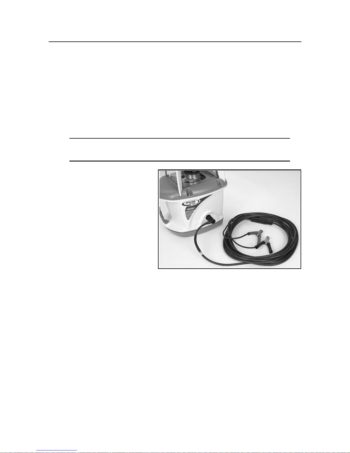
External power cable 20.3
1 Alligator clips (+ and –) – connect
to the positive (+) and negative (–)
terminals on a 12-V DC battery.
2 4-socket plug – connects to the
4-pin receptacle on the laser.
1
2
M100 3½-8 Adapter 20.4
The 3½-8 adapter allows you to connect the laser which has a 5/8-11 threaded
mount to a tripod or other mounting device that has a 3½-8 threaded mount.
M102 Quick-disconnect adapter 20.5
The quick-disconnect adapter allows you to quickly disconnect the laser from the
tripod.
M103 Steep-grade adapter 20.6
The steep-grade adapter allows the internal leveling mechanism of the steep-grade
laser to level the laser at grades greater than 25%.
1243 Sighting scope (GL710 and GL720 only) 20.7
The sighting scope allows manual alignment of the grade axis to a known reference
point. This scope is not required for a radio remote-control laser.
10 GL700 Series Laser Transmitter User Guide

CHAPTER
How to Use the
Laser System 3
3
Powering the Laser – Batteries 3.1
Depending on the laser system configuration that you purchase, the laser is shipped
with either rechargeable nickel-cadmium (Ni-Cd) or nickel/metal-hydride (Ni-MH)
batteries.
Temperature affects battery-charging time. For the best results, charge the batteries
when the ambient temperature is in the range from 10 °C to 40 °C (50 °F to 104 °F).
Charging at a higher temperature may damage the batteries. Charging at a lower
temperature may increase the charge time and decrease the charge capacity,
resulting in loss of performance and shortened battery-life expectancy.
Even if you buy a laser that uses Ni-Cd batteries, you can upgrade to Ni-MH
batteries. The upgrade installation, however, must be performed by an authorized
service center.
Alkaline batteries can also be used as a backup; however, rechargeable batteries
should be reinstalled in the laser as soon as possible.
To let you know when the batteries are getting low, the status LED flashes. When
the status LED flashes yellow, the laser has less than one hour of running time.
When the status LED remains on solid yellow, the batteries have less than five
minutes running time.
After shipment, the batteries may not have enough power to operate the system. Be
sure to recharge the batteries before use. The intelligent recharger maximizes
battery life and reduces the time before battery replacement by precisely controlling
the recharging/discharging cycle and by not overcharging the batteries. The
maximum time to achieve a full charge is six hours.
GL700 Series Laser Transmitter User Guide 11
3 How to Use the Laser System
Recharging the batteries 31.1
Note – Do not recharge alkaline
batteries. Trying to recharge them does
not damage the laser but the batteries do
not recharge.
1. Plug the 4-socket plug into the laser
and tighten the retaining collar.
2. Plug the supplied grounded electrical
power cord into the batteryrecharger.
3. Plug the grounded electrical power
cord into an appropriate outlet.
Note – The recharging status is
indicated on the recharger.
Left LED Right LED Recharging Status
Off Off No connection or no batteries
Off On Recharging is in progress
Flashing Off Recharging is complete
Flashing Flashing Recharging error
Note – The laser will not operate while the batteries are recharging.
Note – Some countries or local areas have regulations regarding the disposal of
rechargeable batteries. Please be sure to follow the regulation in your area.
12 GL700 Series Laser Transmitter User Guide
3 How to Use the Laser System
Installing/removing the batteries 30.1
Warning – The Ni-CD and Ni-MH batteries may contain small amounts of
C
harmful substances.
– Be sure to charge the battery before using it for the first time, and after not
using it for an extended length of time.
– Charge only with specified chargers, according to device manufacturer's
instructions.
– Do not open the battery, dispose of it in a fire, or short circuit it. These
actions may cause the battery to ignite, explode, leak, or get hot, causing
personal injury.
– Dispose in accordance with all applicable federal, state, and local
regulations.
– Keep the battery away from children. If swallowed, do not induce vomiting.
Seek medical attention immediately.
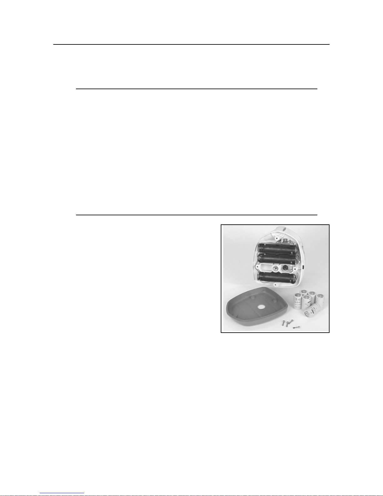
1. Remove the four screws from the battery
housing. Remove the battery-housing
compartment.
2. Install/remove the batteries.
Note – When installing the batteries, be sure
to note the positive (+) and negative (-)
diagram inside of the housing.
Note – The laser has reverse polarity
protection. If the batteries are put in wrong,
no damage occurs to the laser but it does not
work. Allow it one minute to recover after the
batteries have been installed correctly.
3. Put the battery-housing compartment in place and reinstall the four screws.
GL700 Series Laser Transmitter User Guide
13
3 How to Use the Laser System
Powering the Laser – External Cable 3.1
The laser system also includes an external power cable so you can operate the laser
in case the internal batteries become discharged. The internal batteries will not
recharge, however, while you’re using the external power cable.
Connecting/disconnecting the external power cable31.1
Caution – To avoid damaging the laser, make sure the laser is off before
C
1. Connect the alligator clips to a
connecting or disconnecting the external power cable to/from the laser.
12-V DC automotive or
motorcycle battery noting the
correct polarity (red =
positive, black = negative).
2. Plug the 4-socket plug into the
laser and tighten the retaining
collar.
3. To disconnect the external
power cable from the laser,
loosen the retaining collar,
unplug the 4-socket plug from the laser, and remove the alligator clips from the
battery.
14 GL700 Series Laser Transmitter User Guide
3 How to Use the Laser System
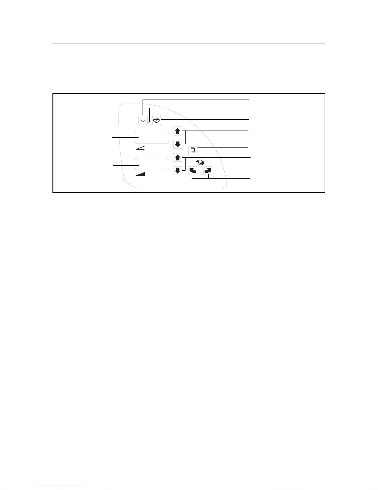
Learning the Basic Laser Functions 3.1
Power
LED
ON
OFF
Manual
1 Up/Down
1 axis LED
Rotation control
RPM
2 axis LED
Figure 3.3 Laser control buttons
2 Up/Down
Axis alignment
Turning on/off the laser 31.1
1. Press the power button (λ) to turn on the laser.
Note – The laser always powers up in the automatic self-leveling mode. If the
laser is out of its self-leveling range and remains out of it for more than 10
minutes, the laser shuts down completely.
Note – When the laser is initially turned on, the LCD shows the approximate
charge of the batteries, the laser beam’s rotation speed, and manual axisalignment position if it’s other than zero. After the LCD shows this information,
the last-entered grade immediately appears in the LCD. The status LED flashes
green to indicate that the laser is self-leveling. After the laser has self-leveled at
the indicated grade, the laser beam rotates and the status LED stops flashing.
Note – After the laser has been level for more than 15 minutes, the HI alert
activates. If the laser is disturbed (tripod bumped, etc.) so that when it re-levels
the laser beam elevation changes by more than 1/8 in. (3.0 mm), the HI alert
shuts down the laser and rotor, and the status LED flashes red two times per
second (twice the manual-mode rate).
2. To turn off the laser, press and hold the power button for three seconds.
GL700 Series Laser Transmitter User Guide
15

3 How to Use the Laser System
Selecting the rotation speed 30.1
The laser has three laser beam rotation speeds—300, 600, and 900 rpm. The
rotation speed can be changed at any time to meet your job-site conditions. Use 600
rpm for held-held receivers and most machine-control systems.
• Repeatedly press and release the rotation-control button (ρ) until the desired
rotation speed appears in the LCD.
Note – The selected rotation speed briefly appears in the LCD. After a few
seconds, the selected percentage of grade appears in the LCD.
Changing the grade value 30.2
The grade value for both axes can be changed using two methods—standard and
quick-change. The standard method is used for entering small changes in the grade
value. The quick-change method is used for setting grade to zero and entering large
changes in the grade value.
Standard method
• Press and hold the up or down button for the axis you want to change until the
correct grade value appears in the laser’s LCD.
Note – The speed of the grade value change increases with the amount of time
the button is held down.
Note – Grade values from -0.500 to 9.999% are displayed in thousandths of a
percent. Grade values greater than 10% are displayed in hundredths of a
percent.
Note – On all models, all changes to the axis-alignment rotation made before
you change the grade value using the standard method are retained.
Quick-change method
Note – The grade value can be quickly set to 0.000% by simultaneously pressing
and holding the up and down buttons for the axis you want to change.
1. Simultaneously press and hold the up and down buttons for the axis you want to
change to set the grade value to 0.000%.
Note – The grade value for the
grade value for the 1 axis increases in 5.00% increments.
2 axis increases in 1.00% increments. The
16 GL700 Series Laser Transmitter User Guide

3 How to Use the Laser System
2. Continue pressing and holding the up and down buttons until the correct grade
value appears in the laser’s LCD.
Note – When the grade value for either axis reaches its highest amount, the grade
value switches to the lowest value for that axis. In the
value switches from +10.00% to –10.00%. In the 1 axis, the value switches from
25.00% to -0.500%. For steep-grade lasers, the value switches from 110.00% to
–0.500%.
Note – On models 722 and 742 only, all changes to the axis-alignment rotation
made before you change the grade value using the quick-change method are
cancelled.
2 axis, for example, the
Activating/deactivating manual mode 30.1
Manual mode bypasses the laser’s automatic self-leveling mode so you can use the
laser in vertical mode. Manual mode also allows you to tilt the laser beyond its
built-in sloping capability so you can perform steep-sloping horizontal applications.
1. Make sure the laser is on and in the orientation appropriate for your application
needs (horizontal or vertical).
2. Press the manual mode button (μ).
Note – When manual mode is activated, the status LED flashes red once per
second and scrolling horizontal segments appear in the LCD.
3. To resume automatic self-leveling mode, press the manual mode button again.
Rotating the axis alignment manually 30.1
The axes-alignment buttons (Λ Ρ) allow you to electronically rotate the laser so that
the grade of the laser beam properly aligns to the job-site grade.
1. To make coarse adjustments, look through the sighting guides on top of the
laser and turn the laser on the tripod until it is properly aligned.
2. To make fine adjustments, press and hold the axis-alignment button that
corresponds to the direction you want to rotate the laser’s axis until the desired
rotation has been reached.
Note – A vertical line in the LCD moves to the left or right to give you a rough
indication of the rotation position.
GL700 Series Laser Transmitter User Guide
17

3 How to Use the Laser System
Two-Way Radio Remote Control
(Radio equipped lasers only) 3.1
Installing/removing the radio remote control
batteries 31.1
Warning – The Ni-CD and Ni-MH batteries may contain small amounts of
C
harmful substances.
– Be sure to charge the battery before using it for the first time, and after not
using it for an extended length of time.
– Charge only with specified chargers, according to device manufacturer's
instructions.
– Do not open the battery, dispose of it in a fire, or short circuit it. These
actions may cause the battery to ignite, explode, leak, or get hot, causing
personal injury.
– Dispose in accordance with all applicable federal, state, and local
regulations.
– Keep the battery away from children. If swallowed, do not induce vomiting.
Seek medical attention immediately.
18 GL700 Series Laser Transmitter User Guide

1. Turn the battery-housing knob
counterclockwise to release the batteryhousing door.
2. Install/remove the batteries.
Note – When installing the batteries, be
sure to note the positive (+) and negative
(-) diagram inside of the housing.
Note – The radio remote control has
reverse-polarity protection. If the
batteries are put in wrong, no damage
occurs to the radio remote control but it
does not work. Allow it one minute to
recover after the batteries have been
installed correctly.
3 How to Use the Laser System
3. Put the battery-housing door in place and
turn the battery-housing knob clockwise.
GL700 Series Laser Transmitter User Guide
19

3 How to Use the Laser System
Learning basic radio remote control functions 30.1
The radio remote control is a hand-held
device that allows you to send operational
commands to the laser from a remote
location. While using the radio remote
control, make sure its antenna is pointing
skyward. For example, if you’re holding the
radio remote control in your hand and using
it in the horizontal orientation, the antenna
should be at a 90° angle to the radio remote
control.
If you connect the radio remote control to a
grade rod, and the radio remote control is
oriented vertically, the antenna should point
upward from the top of the radio remote
control.
20 GL700 Series Laser Transmitter User Guide

3 How to Use the Laser System
Turning on/off the radio remote control
1. Press the power button (π)to turn on
the radio remote control.
Note – When the radio remote control
is initially turned on, the axes symbols
Up
and last-entered grade for each axis
appear in the LCD.
Down
Mode
MODE
Enter
2. To turn off the radio remote control,
press and hold the power button for
Manual
Power
3 seconds.
Selecting the operational mode
The mode button allows you to choose the laser’s operational mode, which includes
automatic axis alignment, grade matching, PlaneLok, grade reverse, and beam
rotation speed. A “hidden” button sequence also allows you to calibrate the laser
from the radio remote control (see the “Calibration” section of this manual for more
information).
1. Repeatedly press and release the mode button to cycle through the operational
mode menu. The menu selections appear in the radio remote control’s LCD.
Confirming the operational mode
1. Press the mode button (μ) to select the operational mode appropriate for your
application needs.
2. Press the enter button (
ε) to confirm your selection.
Activating/deactivating the backlighting feature
• Press and hold the enter button to activate backlighting. Backlighting turns off
automatically to save battery life.
Selecting the rotation speed
The laser has three laser beam rotation speeds—300, 600, and 900 rpm. The
rotation speed can be changed at any time to meet your job-site conditions. Use 600
rpm for held-held receivers and most machine-control systems.
GL700 Series Laser Transmitter User Guide
21

3 How to Use the Laser System
1. Select “Rotation Speed” from the operational mode menu using the mode
button (μ).
2. Repeatedly press and release the radio remote control’s up (
υ) or down (δ)
button until the desired rotation speed has been selected.
Note – The rotation speed appears in the two-way radio remote control’s LCD.
Changing the grade value
The grade value for both axes can be changed using two methods—standard and
quick-change. The standard method is used for entering small changes in the grade
value. The quick-change method is used for setting grade to zero and entering large
changes in the grade value. The grade value flashes 1 time per second while the
laser is leveling to the new grade value. Once level, the grade display stops flashing.
Standard method
Note – The last-entered grade value for each axis appears in the radio remote
control’s LCD.
1. Select the desired grade axis (1 or 2) from the operational mode menu
using the mode button (Μ).
2. Press and hold the up (
until the desired grade value appears in the laser’s LCD.
υ) and down (δ) button for the axis you want to change
Note – The speed of the grade value change increases with the amount of time the
button is held down.
Note – Grade values on the radio remote control are displayed in thousandths of a
percent.
Note – On all models, all changes to the axis-alignment rotation made before you
change the grade value using the standard method are retained.
22 GL700 Series Laser Transmitter User Guide

Quick-change method
3 How to Use the Laser System
1. Select the desired grade axis (
using the mode button (Μ).
2. Simultaneously press and hold the up (υ) and down (δ) buttons for the axis you
want to change to set the grade value to 0.000%.
Note – The grade value for the
grade value for the
3. Continue pressing and holding the up and down buttons until the desired grade
value appears in the laser’s LCD.
Note – When the grade value for either axis reaches its highest amount, the grade
values switches to the lowest value for that axis. In the
value switches from +10.00% to –10.00%. In the 1 axis, the value switches from
25.00% to –0.500%. For steep-grade lasers the value switches from 110.0% to
–0.500%.
Note – On models 722 and 742 only, all changes to the axis-alignment rotation
made before you change the grade value using the quick-change method are
cancelled.
1 axis increases in 5.00% increments.
1 or 2) from the operational mode menu
2 axis increases in 1.00% increments. The
2 axis, for example, the
GL700 Series Laser Transmitter User Guide
23

3 How to Use the Laser System
Activating/deactivating manual mode
Manual mode bypasses the laser’s automatic self-leveling mode so you can use the
laser in vertical mode. Manual mode also allows you to tilt the laser beyond its
built-in sloping capability so you can perform steep-sloping horizontal applications.
1. Press the manual mode button (Μ).
Note – When manual mode is activated, the laser’s status LED flashes red once
per second and scrolling horizontal segments appear in the laser’s LCDs.
2. Use the up (
change the slope or line of the laser beam. As you press the up and down or left
and right buttons, the symbol for the grade axis you are changing appears in the
LCD (
3. To resume automatic self-leveling mode, press the manual mode button again.
υ) and down (δ) or left (ν) and right (σ) buttons to electronically
1 or 2).
Activating automatic-axis-alignment, grade-matching, and
PlaneLok modes
Note – For more detailed information about these modes, please see the System
Setup section of this manual.
1. Select the desired mode from the operational mode menu using the mode
button (
2. Select the axis (
control’s up (
3. Press the enter button (
4. While the system is aligning, “Start” followed by “Wait” appears in the radio
remote control’s LCD.
Μ).
1 or 2) that you are aligning using the radio remote
υ) or down (δ) buttons.
ε) to confirm the selection.
5. When the alignment has been completed, “Complete” appears in the radio
remote control’s LCD.
Note – Alignment can take one to five minutes to complete.
24 GL700 Series Laser Transmitter User Guide

3 How to Use the Laser System
Activating/deactivating standby mode
Standby mode, which can only be activated by using a two-way radio remote
control, is a power-saving feature that conserves laser battery life.
1. Quickly press and release the radio remote control’s power button (
ε) to
activate standby mode.
Note – When standby mode is activated, the laser beam, rotor, self-leveling
system, and LEDs shut down while the HI-alert function still checks the laser
setup. So that you know that the laser is in standby mode rather than being
turned off, dashed lines appear in the laser’s LCD. In the radio remote control’s
LCD, the word “standby” appears.
2. To deactivate standby mode and restore full operation of the laser, quickly press
and release the radio remote control’s power button again. The laser and all
other functions turn on again.
GL700 Series Laser Transmitter User Guide
25

3 How to Use the Laser System
26 GL700 Series Laser Transmitter User Guide

CHAPTER
System Setup 4
4
General Setup Information 4.1
• Prior to beginning work, decide where to place the laser for optimum coverage
of the job site.
• Place the laser on the job site where it will be out of the way of traffic and will
not be obstructed by equipment with respect to the machine-mounted receiver.
• Set the height of the tripod and laser so that the laser beam will strike the
receiver when it’s positioned correctly on a machine or grade rod.
• Adjust the laser’s alignment to the job site as needed.
• When using the radio remote control, make sure the radio remote control’s
antenna is pointing skyward and the laser’s antenna is flipped up. An “R”
appears in the right corner of the remote’s first display line indicating a
connection to the receiver has been made and the power is on.
• When the radio remote control and laser are “linked,” a flashing bar above the
“T” (antenna icon) appears in the right corner of the radio remote control’s
LCD.
• The laser-beam operating radius for the standard laser models is 460 m
(1,500 ft).
• The radio-remote-control operating radius for the standard operating modes is
230 m (750 ft). The operating radius for the radio remote control in automatic
alignment modes is 150 m (500 ft).
GL700 Series Laser Transmitter User Guide 27

4 System Setup
Getting Connected 4.2
Laser 42.1
Connecting the laser to a tripod
All lasers have a 5/8-11 tripod mount on the bottom of the laser so you can connect
the laser to a standard tripod, column clamp, or other mounting device. The laser
can also be used without a tripod, but the laser must be set on a stable surface.
In addition to using the laser in horizontal mode, you can use it in vertical mode. To
do so, however, an after-market vertical mounting bracket is needed. For instruction
on how to use the vertical mounting bracket, consult the specific manufacturer’s
instructions.
1. Insert the tripod’s 5/8-11 screw into the
laser’s threaded 5/8-11 tripod mount.
2. Turn the screw counterclockwise to hold the
laser securely in place.
3. To detach the laser from the tripod, turn the
screw clockwise.
28 GL700 Series Laser Transmitter User Guide

System Setup 4
Connecting the laser to the adapters
Depending on the laser system you purchase, additional mounting accessories may
be shipped with your laser. The steep-grade laser system includes a steep-grade
adapter.
M100 3 1/2-8 and M102 Quick-disconnect adapters
• Thread the appropriate adapter into the 5/8-11 threaded mount on the bottom of
the laser.
Note – The carrying case is designed so the adapter can remain on the laser.
M103 Steep-grade adapter
1. Set up a tripod so that its mounting surface is as close to true level as possible.
Make sure that one of the tripod legs is aligned to the down-grade side of the
1 axis of the laser.
2. Make sure that the steep-grade adapter is connected to the laser at the mark that
indicates the required grade range.
3. Connect the steep-grade adapter to the tripod.
GL700 Series Laser Transmitter User Guide
29

4 System Setup
Radio remote control 40.1
Connecting the remote holster to a grade rod
• Wrap the mounting strap around the grade rod and
fasten it securely in place.
Connecting the radio remote control to the remote holster
• Slip the radio remote control mounting clip into the
mounting slot of the remote holster.
30 GL700 Series Laser Transmitter User Guide

System Setup 4
Setting Up the Laser System 4.1
Setting up the laser in manual mode 41.1
1. Press the manual mode button (μ) on
the laser or radio remote control.
Note – When manual mode is
activated, the laser’s status LED
flashes red at a 1-Hz rate and
scrolling horizontal segments appear
in the laser’s LCDs. If you are using
a two-way radio remote control,
“Manual Mode” also appears in the
radio remote control’s LCD.
2. To adjust the laser in the 1 axis so
that the laser beam matches the
desired grade, use the up (
υ) and
down (δ) buttons on the laser or
radio remote control.
ON
OFF
Manual mode
1 Up/Down
RPM
2 Up/Down
Axis
alignment
3. To adjust the laser in the 2 axis so
that the laser beam matches the
desired grade, use the up and down
buttons on the laser or the left (
and right (
σ) buttons on the radio
ν)
remote control.
4. To resume automatic self-leveling
mode, press the manual button on
the laser or radio remote control
again.
Mode
Manual
MODE
Up
Down
Enter
Power
GL700 Series Laser Transmitter User Guide
31

4 System Setup
Aligning the axis manually 40.1
The manual axis alignment buttons (Λ Ρ) are primarily used on lasers that don’t
have radio remote control capability. These buttons rotate the grade axis
electronically (simulates turning the laser on its tripod, with fine adjustment
capability up to a maximum of ±40 degrees).
1. Set up the laser over a reference point. Make sure the laser is positioned so that
the 1 axis and 2 axis are pointing in the right direction.
2. Using the sighting guides as a guide, rotate the laser on its tripod to align the
laser to the direction hub.
3. Turn on the laser and allow it to self-level. Set the grade value on both axes to
zero.
4. Connect a receiver to a grade rod and turn on the receiver.
5. Set the grade rod on the direction hub and adjust the receiver until you get an
on-grade reading.
Note – If only one person is manually aligning the laser, use a bipod (commonly
used with prism poles) to keep the grade rod plumb when placing it on the
direction hub.
6. Change the grade value on the cross axis, for example, to 4%. Press the
appropriate manual axis alignment button to align the laser plane to the receiver.
The clockwise axis alignment button (
Λ) rotates the laser clockwise; the
counterclockwise axis alignment button (Ρ) rotates the laser counterclockwise.
7. Press and hold the axis alignment button until you get an on-grade reading on
the receiver again. Then dial the grade value appropriate to your application on
one or both axes.
32 GL700 Series Laser Transmitter User Guide

System Setup 4
Setting up the laser in vertical mode 40.1
1. Set up the laser on its side.
Note – If you’re using the laser with a tripod, an after-market vertical mounting
bracket is needed. For instruction on how to use the vertical mounting bracket,
consult the specific manufacturer’s instructions.
2. Press the manual button (μ) on the laser or radio remote control.
3. To adjust the laser beam for line direction, use the 1 axis up (υ) and down (δ)
buttons on the laser or radio remote control until the laser beam matches the line
point.
4. To adjust the plumb position of the laser beam, use the up and down buttons on
the laser or the left (
ν) and right (σ) buttons on the radio remote control.
Establishing Control 4.1
Determining height of instrument (HI) 41.1
1. Set up the laser and turn it on.
2. Connect a receiver to a grade rod.
Turn on the receiver.
3. Place the grade rod on a job-site
benchmark (BM). Adjust the height
of the receiver until the receiver’s
LCD shows an on-grade reading.
4. Add the grade-rod reading to the
benchmark to determine the height
of instrument. Use the HI as a
reference for all other elevation
measurements.
Height of instrument (HI)
4.34 Rod
reading
100.23
Benchmark
HI = Rod reading + Benchmark
HI = 4.34 + 100.23 = 104.57
GL700 Series Laser Transmitter User Guide
33

4 System Setup
Establishing elevation-control hubs 40.1
The elevation-control hub can be used to
re-establish the elevation of the laser plane
in case the laser setup gets disturbed.
• Establish an elevation-control hub
close to the laser and determine the HI.
Note – If you’re also going to establish
grade-control hubs, make sure the
Elevation
control hub
elevation-control hub and one of the
grade-control hubs are on the same axis.
Establishing grade-control hubs 40.2
The grade-control hub can be used to check the alignment of the laser on the job site
and to confirm the grade entered into the laser.
• Check the grade on a minimum of
three hubs on the job site. The hubs
should be in lines that are 90° from
one another with one line
containing two hubs.
Note – Because the accuracy of this
procedure is based on the known
elevation of the hubs, the exact
elevation of the hubs is critical.
Grade
control hubs
Note – If there isn’t enough space for
the laser to be setup on the desired
centerline, the laser can be set up on a
line parallel to the centerline (D1=D2).
34 GL700 Series Laser Transmitter User Guide
Parallel
Line
D2
D1

System Setup 4
Reversing the Grade
(Two-way radio remote control) 4.1
The sign of the 2 axis can be changed using the two-way radio remote control.
1. Set up the laser. Turn on the laser and flip its antenna up.
2. Turn on the radio remote control and make sure its antenna is pointing skyward.
3. Select “2 Reverse” from the menu using the mode button (Μ).
4. Press the enter button (ε) to confirm the selection.
Note – On a two-way radio remote
control, the sign of the 2 grade
value reverses to indicate that
C
L
2 reversing has been completed.
1.000
2.000
C
L
0
+2.0
GL700 Series Laser Transmitter User Guide
-2.00
1.000
-2.000
35

4 System Setup
36 GL700 Series Laser Transmitter User Guide

CHAPTER
Automatic
Alignment Modes 5
5
Summary 5.1
The laser system has three automatic alignment modes:
• Axis Alignment
• Grade Matching
• PlaneLok
To use these modes, a radio remote control and hand-held receiver are required. The
radio remote control and receiver are typically mounted to a grade rod, which must
be placed somewhere between 20 m (60 ft) and 150 m (500 ft) from the laser.
Automatic axis alignment can take from 1 – 5 minutes to complete.
Automatic axis alignment mode 51.1
This automatic axis alignment function replaces the manual alignment scope and
vernier base traditionally used to align the desired grade axis to a hub.
When this mode is being used, the receiver and radio remote control are mounted to
a grade rod, the desired grade is dialed into the laser, and the grade rod is placed on
the hub that the grade axis is being aligned to. When activated, automatic axis
alignment mode adjusts the direction the desired grade axis is pointing to by
electronically simulating “rotating” the laser on its mounting base. This mode is
typically used for agriculture, road construction, and steep-grade applications where
precision alignment of the grade axis is required.
GL700 Series Laser Transmitter User Guide 37

5 Automatic Alignment Modes
Grade-matching mode 51.2
This automatic alignment function changes the grade of the desired axis to
automatically match an unknown grade.
When this mode is being used, the receiver and radio remote control are mounted to
a grade rod, the approximate grade (within 1.5° of the actual grade) is dialed into
the laser, and the grade rod is benchmarked to the laser-beam elevation at a point
within 1 m (3 ft) of the laser. Without changing the receiver’s elevation on the rod,
the grade rod is then placed anywhere a grade reading is needed.
When activated, grade-matching mode automatically adjusts the grade up or down
to “search” for the receiver. When the center of the receiver is found, the resultant
grade is calculated and dialed into the laser, and displayed on the two-way radio
remote control.
When grade matching is complete, the receiver can be removed from the alignment
point and the calculated grade will remain in the laser. Both axes of the laser can be
grade matched in sequence. Grade-matching mode is used for applications where
the existing grade is not known, but will remain relatively unchanged (such as
installation of a sidewalk or driveway).
PlaneLok mode 51.3
PlaneLok mode works like grade-matching mode, except the receiver is
permanently mounted to the desired elevation so that the laser can use the receiver
to continually monitor beam elevation. The laser ignores the internal level vial for
that axis, using the absolute elevation from the receiver for level control.
PlaneLok Mode is used for applications where extreme precision of the laser-beam
elevation is required, such as runway applications.
38 GL700 Series Laser Transmitter User Guide

Automatic Alignment Modes 5
Using Axis-Alignment and Grade-Reverse
Modes
5.2
How axis-alignment mode works 52.1
Axis-alignment mode works by changing grade in the aligned-axis direction and
cross-axis directions then monitoring the elevation changes of the laser beam at the
receiver via the radio remote control. The desired axis-alignment angle can then be
calculated and the internal grade system “rotated” electronically to align the
simulated grade axis to the desired point.
Important things to know 52.2
Automatic Axis Alignment:
• Replaces the alignment scope and vernier base traditionally used
• Can be done from any side of any axis of the laser, even if grade is dialed into
the opposite axis that’s being aligned
• Automatically adjusts the direction the grade axis is pointing to the
receiver/remote location
• Electronically simulates rotating the laser on its base to match the hub
For Proper Operation:
• The desired grades must be entered into the laser
• The receiver must be at the correct alignment point
• The receiver must be between 20 m (60 ft) and 150 m (500 ft) from the laser
For Best Accuracy:
• The laser beam must strike the receiver's photocell. You do not need to adjust
the receiver to an on-grade reading.
• Set up the laser to align to the elevation reference the farthest away (such as the
centerline of the road)
• If the hubs are equally distant, align to the hub with the smallest amount of
grade
GL700 Series Laser Transmitter User Guide
39

5 Automatic Alignment Modes
Applications 52.3
Road construction
The main uses for the laser in road construction are for planar sections where the
road design calls for no vertical or super-elevated curves.
Automatic axis alignment mode
1. Set up the laser over a point on the centerline of the road.
2. Using the sighting guide as a guide, rough align the laser with the direction hub
on the centerline.
Note – Because the laser can
provide positive and negative
grades in the 2 axis, make
sure the laser’s handle is at a
90° angle to the centerline of
the road.
Direction hub
C
L
Grade control
hub
Note – If there isn’t enough
space for the laser setup on the
centerline, the laser can be set
Parallel
line
up on a line parallel to the
centerline of the road (D1 and
D2 are the same distance).
3. Enter the grade value for the axis that
aligns with the centerline of the road (
Reference point
1).
Same
distance
1.00
Direction hub
centerline
Grade control hub
1.000
0.000
C
L
40 GL700 Series Laser Transmitter User Guide

4. Enter the grade value for the side of the
road to be graded first into the axis that
is perpendicular to the centerline of the
road (
2).
Automatic Alignment Modes 5
1.000
C
L
2.000
5. Connect a receiver and radio remote
control to a grade rod.
6. 0Set the grade rod on the centerline
direction hub.
7. Slide the receiver up/down the grade
rod until the laser beam strikes the
receiver's photocell.
8. Select “Axis Align” from the
operational menu using the radio
remote control’s mode button (
9. Select the axis (1 or 2) that you are aligning using the up (υ) or down (δ)
buttons.
10. Press the enter button (ε) to confirm the selection. “Start” then “Wait” appears
on the LCD.
11. Hold the grade rod plumb and steady during automatic axis alignment.
Note – Alignment can take from 1 to 5 minutes to complete.
Μ).
2.00
Note – When axis alignment has been completed, “Axis Align Complete”
appears in the LCD. If axis alignment fails, a failure message appears in the
LCD.
12. Check the laser’s alignment and grade values using previously established
elevation-control hubs and grade-control hubs as references.
Note – If the alignment and grade values need small adjustments, they can be
changed using the radio remote control. See the “Correcting Grade/Height
Differences” section of this manual for more information.
13. Grade that side of the road.
GL700 Series Laser Transmitter User Guide
41

5 Automatic Alignment Modes
Grade reverse mode
Note – After you’ve finished grading
one side of the road, you can reverse
the sign of the
2 axis from the cab
using the radio remote control.
1. Set the blade on a known elevation
hub on the centerline of the road.
2. Select “2 Reverse” from the
operational menu using the radio
remote’s mode button (Μ).
C
L
1.000
2.000
1.000
-2.000
3. Press the enter button (ε) to
confirm the selection.
+2.0
C
L
0
-2.00
42 GL700 Series Laser Transmitter User Guide

Automatic Alignment Modes 5
Steep grade (embankments, waste dumps, and sea walls)
1. Set up a tripod on an established
offset from the baseline of the
bank to make sure that the laser
beam will be at the required
height above the bank surface.
Direction hub
90°
Make sure that one of the tripod
legs is aligned with the downgrade side of the
2. Connect the steep-grade adapter
to the tripod.
3. Make sure that the steep-grade adapter points to the laser with the mark that
1 axis.
Baseline
Steep grade axis
90°
90°
Baseline hub 1
indicates the required grade range.
4. Align the adapter with the direction hub on the top of the bank.
Baseline hub 2
Offset
5. Connect the laser to the steep-
grade adapter making sure that
the laser’s handle is parallel
with the baseline of the bank.
6. Make sure the desired grade and
rotation speed are entered into
the laser.
7. Using the sighting guides as a
guide, rough align the laser with
the direction hub.
8. Connect a receiver and radio
remote control to a grade rod.
9. Set the grade rod on the direction hub.
10. Slide the receiver up/down the grade rod until the laser beam strikes the
receiver's photocell.
Note – The grade rod must be plumb.
11. Select “Axis Align” from the operational menu using the radio remote control’s
mode button (Μ).
GL700 Series Laser Transmitter User Guide
43

5 Automatic Alignment Modes
12. Select the axis (1 or 2) that you are aligning using the up (υ) or down (δ)
buttons.
13. Press the enter button (ε) to confirm the selection. “Start” then “Wait” appears
on the LCD.
14. Hold the grade rod plumb and steady on the direction hub.
Note – Alignment can take 1 to 5 minutes to complete.
Note – When axis alignment has been completed, “Axis Align Complete”
appears in the LCD. If axis alignment fails, a failure message appears in the
LCD. (See the “Troubleshooting” section of this manual for more information.)
15. Check the laser’s alignment using previously established direction hub and
baseline hubs as references.
Note – If the alignment and grade values need small adjustments, they can be
changed using the radio remote control. See the “Correcting Grade/Height
Differences” section of this manual for more information.
Note – If the axis alignment should be done
to the baseline hub #2 (perpendicular to the
steep grade axis), make sure that the tripod
mount is aligned with the reference point at
the baseline. Follow the steps as described
above with the only change that the axis
alignment using the grade rod has to be done
at baseline hub #2 (steps 7, 9, and 14)
instead of the direction hub.
44 GL700 Series Laser Transmitter User Guide

Automatic Alignment Modes 5
Using Grade-Matching Mode 5.1
How grade-matching mode works 51.1
Grade-matching mode works by changing grade in the selected axis direction then
monitoring the elevation changes of the laser beam at the receiver via the radio
remote control. Once the laser “finds” the center of the receiver, the resultant grade
is calculated and stored in the laser and two-way remote control.
Important things to know 51.2
Grade-Matching Mode:
• Automatically adjusts the grade of the selected axis to match an unknown grade
• Searches for and finds “on-grade” of the mounted receiver within a 1.5° grade
range of the final grade (starting with the beam centered on the receiver isn’t
necessary)
• Stores and displays the resultant grade on the remote and laser
For Proper Operation:
• The receiver can be removed after alignment, and the resultant grade remains in
the laser
• One or both axes can be grade matched in sequence
• The initial grade must be within 1.5° of the final grade before starting
GL700 Series Laser Transmitter User Guide
45

5 Automatic Alignment Modes
Application 51.3
General construction
One axis
If the2 axis is not at 0% grade, the laser has to be aligned in automatic axis
alignment mode with grade-control hub #2 before the grade-matching mode can be
activated.
1. Set up the laser over the reference
point.
2. Using the sighting guide as a guide,
rough align the laser with gradecontrol hub #2.
Note – The laser and control hub #1
must be on one axis, which is at 0%
grade.
2
22.00
0.00
3. Enter the approximate grade value for
the 1 axis and 0% for the 2 axis.
1
Reference point
Note – The automatic grade-searching range is ±1.5°. The approximated grade
should be within 1.5° of the final matched grade.
4. Connect a hand-held receiver and radio remote control to a grade rod.
5. Set the grade rod on control hub #1.
6. Slide the receiver up/down the grade rod until the receiver’s LCD shows an on-
grade reading.
Note – The grade rod must be plumb.
7. Go to grade-control hub #2 and set the grade rod on the hub. Make sure you
do not change the height of the receiver on the grade rod.
8. Select “Grade Match” from the operational menu using the mode button (Μ).
9. Select the axis (1 or 2) that you are aligning using the up (υ) or down (δ)
buttons.
10. Press the enter button (ε) to confirm the selection. “Start” then “Wait” appears
in the radio remote control LCD.
46 GL700 Series Laser Transmitter User Guide

Automatic Alignment Modes 5
11. Hold the grade rod plumb and steady on grade-control hub #2 during grade
matching.
Note – “Grade Match Complete” appears in the radio remote control’s LCD when
grade matching has been completed. If grade matching fails, a failure message
appears in the radio remote control LCD. (See the “Troubleshooting” section of
this manual for more information.)
Note – The resultant grade appears in the laser’s LCD display and on the two-way
remote control’s LCD display.
Note – Alignment can take 1 to 5 minutes to complete.
Two axes
This function can only be done on one axis at a time. The laser needs to be aligned
with one of the grade-control hubs in automatic axis alignment mode before dual
axes grade-matching mode can be activated.
1. Set up the laser over a reference point.
2. Using the sighting guide as a guide, rough align the laser with the grade-control
hub #1.
Note – The two grade-control hubs must be
in lines that are at a 90° angle from one
Grade control
hub 1
another.
Note – The laser, elevation-control hub, and
grade-control hub #2 must be on one axis.
3. Enter the approximate grade value for the
1 axis and the 2 axis.
Note – The automatic grade searching range
is ±1.5°. The approximated grade should be
Elevation
control hub
within 1.5° of the final matched grade.
4. Connect a hand-held receiver and radio remote control to a grade rod.
5. Set the grade rod on the elevation-control hub.
6. Slide the receiver up/down the grade rod until the receiver’s LCD shows an
on-grade reading.
Note – The grade rod must be plumb.
Grade
control hub 2
GL700 Series Laser Transmitter User Guide
47

5 Automatic Alignment Modes
7. Go to grade-control hub #1 and set the grade rod on the hub. Make sure you
do not change the height of the receiver on the grade rod.
8. Select “Grade Match” from the operational menu using the mode button (Μ).
9. Select the axis (1 or 2) that you are aligning using the up (υ) or down (δ)
buttons.
10. Press the enter button (ε) to confirm the selection. “Start” then “Wait” appear in
the LCD.
11. Hold the grade rod plumb and steady on grade-control hub #1 during grade
matching.
Note – “Grade Match Complete” appears in the radio remote control’s LCD
when grade matching has been completed. If grade matching fails, a failure
message appears in the radio remote control’s LCD. For more information, see
Troubleshooting, page 59.
Note – The matched grade value for the aligned axis appears in the laser’s and
two-way radio remote control’s LCDs.
Note – Alignment can take 1 to 5 minutes to complete.
12. Go to grade-control hub #2 and set the grade rod on the hub. Make sure you
do not change the height of the receiver on the grade rod.
13. Select “Grade Match” from the operational menu using the mode button (Μ).
14. Select the axis (1 or 2) that you are aligning using the up (υ) or down (δ)
buttons.
15. Press the enter button (ε) to confirm the selection.
16. Hold the grade rod plumb and steady on grade-control hub #2 during grade
matching.
Note – “Grade Match Complete” appears in the radio remote control’s LCD when
grade matching has been completed. If grade matching fails, a failure message
appears in the radio remote control’s LCD. For more information, see
Troubleshooting, page 59.
Note – The matched grade value for the aligned axis appears in the laser’s and
two-way radio remote control’s LCDs.
Note – Alignment can take 1 to 5 minutes to complete.
48 GL700 Series Laser Transmitter User Guide

Automatic Alignment Modes 5
Using PlaneLok Mode 5.1
How PlaneLok mode works 51.1
PlaneLok mode works by changing grade in the selected axis direction then
monitoring the elevation changes of the laser beam at the receiver via the radio
remote control. Once the laser “finds” the center of the receiver, it continues to
monitor its position and makes small corrections to hold the beam on-grade.
Important things to know 51.2
• Loss of receiver signal results in laser “out-of-level” mode (no laser beam and
rotation)
• The internal laser level vial for that axis is ignored (the receiver is used for level
control)
• The opposite axis levels to its internal level vial and grade
PlaneLok
• Works like grade match mode, except the receiver is permanently mounted at
the desired elevation to continually monitor beam elevation
• Is used for applications requiring extreme accuracy, such as in runway
applications
For proper operation:
• The initial grade must be within 1.5° of the final grade before starting
GL700 Series Laser Transmitter User Guide
49

5 Automatic Alignment Modes
Applications 51.3
Agricultural and runways
Agriculture and runway applications can generally be handled using any of the
previously described processes. For extremely accurate agriculture or runway
applications whose work-time extends over several days or even weeks, PlaneLok
mode is recommended.
PlaneLok mode
1. Set up the laser over a reference point.
2. Using the sighting guide as a guide, rough align the laser with one of the
grade-control hubs.
Note – The two grade-control hubs must be in
lines that are at a 90° angle from one another.
3. Enter the approximate grade into the axis that
Grade control
hub 1
needs to be aligned and an exact grade value
into the other axis.
Note – The automatic grade searching range
is ±1.5°. The approximated grade should be
within 1.5° of the final matched grade.
4. Connect a receiver and radio remote control
Elevation
control hub
Grade
control hub 2
to a grade rod.
5. Set the grade rod on the elevation-control hub.
6. Slide the receiver up/down the grade rod until the receiver’s LCD shows an
on-grade reading.
Note – The grade rod must be plumb.
7. Go to the grade-control hub on the axis to be aligned and set the grade rod on
the hub. Make sure you do not change the height of the receiver on the grade
rod.
8. Select “PlaneLok” from the operational menu using the mode button (Μ).
9. Select the axis (1 or 2) that you are aligning using the up (υ) or down (δ)
buttons.
50 GL700 Series Laser Transmitter User Guide

Automatic Alignment Modes 5
10. Press the enter button (ε) to confirm the selection. “Start” then “Wait” appears
in the LCD.
Note – When the PlaneLok function has been completed, “PlaneLok Complete”
and a “Lock” icon (padlock symbol) appear in the radio remote control’s LCD.
Note – Alignment can take 1 to 5 minutes to complete.
Note – If the PlaneLok function fails, the remote indicates the cause of failure. See
the ‘Troubleshooting” section of this manual for more information.
Note – The receiver should be
permanently mounted at this location
and at the desired elevation. Use a
bipod (commonly used with prism
Rod/prism pole
with receiver/remote
attached
poles) to hold the grade rod steady for
the entire workday.
Note – The resultant grade on the
locked axis is displayed in the remote
control’s LCD.
Note – The laser continues to servo to
the receiver’s elevation signals. Any
loss of signal over an extended period
of time (1 minute) causes the laser
beam to turn off and rotor to stop. The
PlaneLok mode must be reactivated
when the laser experiences loss of
signal over an extended period.
11. To exit the PlaneLok function, select “PlaneLok” again using the mode button.
Then press the enter button.
Note – As a confirmation, “Exiting” appears in the radio remote control's LCD.
GL700 Series Laser Transmitter User Guide
51

5 Automatic Alignment Modes
Using the Radio Remote Control to Correct
Grade/Height Differences After Setup
5.1
Sometimes, after performing any of the advanced alignment functions, the
alignment and grade values need small adjustments. These adjustments can be made
using a two-way radio remote control.
Two-way radio remote control 51.1
Checking grade/height differences for the 1 and 2 axes
1. Determine the height of the laser (HI)
by setting the grade rod on elevationcontrol hub #1.
2. Check the HI by setting the grade rod
on elevation-control hub #2. Make sure
Elevation
control
hub 1
you do not change the height of the
receiver on the grade rod.
Reference point
Adjusting grade/height differences on the 1 axis
Elevation control hub 2
Elevation
control hub
cross axis
1. Select “1 Grade” from the operational mode menu using the radio remote
control’s mode button (Μ).
2. Press the up (υ) or down (δ) button on the radio remote control until you get an
on-grade reading on the receiver.
Note – The new grade value appears on the radio remote control’s LCD.
Adjusting grade/height differences on the 2 axis
1. Go to the elevation-control hub for the 2 axis and set the grade rod on the hub.
Make sure you do not change the height of the receiver on the grade rod.
2. Select “2 Grade” from the operational mode menu using the radio remote
control’s mode button (
3. Press the up (υ) or down (δ) button on the radio remote control until you get an
on-grade reading on the receiver.
Note – The new grade value appears on the two-way radio remote control’s LCD.
52 GL700 Series Laser Transmitter User Guide
Μ).

CHAPTER
Specifications 6
6
Laser 6.1
Accuracy Single, Dual, and Steep-Grade Models:
Servo Deadband Accuracy: 4.6 arc seconds
Grade Resolution: 0.001%
Diameter: accurate for machine-control and
agricultural applications to 900 m (3,000 ft)
Laser
Type/Classification
Laser Power Output Single-, Dual-, and Steep-Grade Models: 3.5 mW
Operating Temperature –20 °C to 50 °C (–4 °F to 122 °F)
Storage Temperature –40 °C to 60 °C (–40 °F to 140 °F)
Operating Range
(Radius)
Grade Range
(Single-Grade Models)
Grade Range
(Dual-Grade Models)
Grade Range
(Steep-Grade Model)
Rotation Speeds 300, 600, 900 rpm
658 nm IEC Class 2 (Standard models)
785 nm IEC Class 1 (IR Models)
IR Models: Less than 1 mW
Standard and Steep-Grade Models: 460 m (1,500 ft)
2 axis N/A
1 axis –0.500% to 25%
2 axis –10% to 10%
1 axis –0.500% to 25%
2-axis –10% to 10%
1 axis –0.500% to 110%
Self-Leveling Range The laser will self level up to 25% grade
Power Source 6.0 Ah Ni-Cd
8.5 Ah Ni-MH
GL700 Series Laser Transmitter User Guide 53

6 Specifications
Battery Life (Radio
Models)
20 Hours (Ni-Cd)
30 Hours (Ni-MH)
20 Hours (Alkaline, emergency use only)
Recharging Time 6 hours, maximum
Low Battery Operations 1 hour with Ni-Cd batteries
Automatic Shutoff 30 minutes if unable to level
Tripod Screw 5/8-11 standard
3½-8 and quick-disconnect (optional)
Water Resistance Completely sealed and waterproof
Weight 8.4 Kg (18.5 lb)
Size 30 x 25 x 20 cm (H x W x D)
11.75 x 10.0 x 7.75 in.(H x W x D)
54 GL700 Series Laser Transmitter User Guide

Specifications 6
Two-way Radio Remote Control 6.2
Size 13 x 8 x 4 cm (H x W x D)
5 x 3 x 1.5 in. (H x W x D)
Weight 0.5 Kg (1 lb)
Operating Temperature –20 °C to 50 °C (–4 °F to 122 °F)
Storage Temperature –40 °C to 60 °C (–40 °F to 140 °F)
Frequency 2.4 gHz digital
Operating Range
(Standard Functions)
Operating Range
(Automatic Alignment
Functions)
Angular Coverage 360°
User Interface 8 buttons and an LCD
Power Source 2 x AA alkaline
Battery Life 100 hours of typical system (laser with remote)
Line of sight up to 230 m (750 ft)
Line of sight up to 150 m (500 ft)
operation at room temperature.
Battery life can be greatly reduced in cold
temperature or if an unusual amount of
automatic alignment functions are performed.
GL700 Series Laser Transmitter User Guide
55

6 Specifications
56 GL700 Series Laser Transmitter User Guide

CHAPTER
Maintenance and
Care 7
7
Introduction 7.1
You will get years of service from the leveling system by following the maintenance
and care recommendations in this manual. Carry the laser in its moisture-resistant,
field-tested carrying case to safely move the laser from one job to another.
However well the product is designed, mishaps do occur. The most common
problems associated with these are covered in the following areas.
Storage 7.2
Caution – Do not store the laser in a wet carrying case. If the case gets wet,
C
open it and let it dry before storing the laser.
Battery Disposal 7.3
Some countries, states, and local areas have regulations regarding the disposal of
rechargeable batteries. Be sure that replaced batteries are disposed of properly.
System Cleaning 7.4
Use only a good-quality glass cleaner and a soft cloth to clean all external optical
components. A dry cloth used on the laser’s/radio remote control’s optical
components or displays could scratch or damage these surfaces.
Blow off any loose debris before cleaning any surfaces to prevent scratching of
optical surfaces. Monthly, wipe off with a moist, clean cloth any dust or dirt from
the laser’s outer surface and inside the battery housing. Clean all corroded battery
contacts with a pencil eraser or baking soda solution.
GL700 Series Laser Transmitter User Guide 57

7 Maintenance and Care
58 GL700 Series Laser Transmitter User Guide

CHAPTER
Troubleshooting 8
8
Introduction 8.1
If none of the following techniques corrects the problem, take your system to a local
Trimble dealer or authorized service center for evaluation or repair.
GL700 Series Laser Transmitter User Guide 59

8 Troubleshooting
Laser 8.2
Problem Solution
Laser will not turn on • Make sure the batteries have sufficient power and are
installed correctly.
• Make sure the batteries contacts are in proper
working condition.
No signal is received at
the receiver
No laser beam • Make sure the laser is on.
The battery life is short • Make sure high-quality batteries are being used.
Radio remote control is
not working with the laser
• Make sure the receiver is turned on.
• Make sure the batteries have sufficient power and are
installed correctly.
• Make sure the laser is sending out a beam.
• Check for a laser signal with another receiver.
• Make sure the batteries have sufficient power and are
installed correctly.
• Make sure that the laser (standard model) is within its
self-leveling range (up to 25%).
• Switch the laser into manual mode; the laser should
come on.
• When recharging the batteries, make sure the charger
is plugged into an appropriate ac outlet. The batteries
require a minimum charge time of six hours.
• Make sure the antenna is upright.
• If the remote does not work with the laser, the remote
needs to be “matched” to the laser for proper
operation. Return the laser to an authorized service
center for the matching procedure to be performed.
Laser beam not accurate • Check and adjust calibration as needed.
60 GL700 Series Laser Transmitter User Guide
• Return the laser to an authorized service center for
inspection.

Troubleshooting 8
Receiver 8.3
Problem Solution
Receiver does not receive
a laser signal
Receiver occasionally
beeps when it is not in the
laser beam
• Make sure the laser receiver is on.
• Make sure the batteries have sufficient power and are
installed correctly.
• Make sure the batteries contacts are in proper working
condition.
• Make sure the receiver is within the operating range of
the laser.
• Try receiving the laser beam with another receiver.
• Make sure the receiver is not near radar or
high-frequency radio stations.
• Make sure the laser beam is not bouncing off a highly
reflective surface.
GL700 Series Laser Transmitter User Guide
61

8 Troubleshooting
Radio Remote Control 8.4
Problem Solution
Radio remote control not
receiving
Radio remote control is
damaged (may include
loose or broken LCD)
• Clear the failure message by quickly pressing and
releasing the power button (
standby mode. When the laser is in standby mode,
quickly press and release the power button again to
return to normal operating mode with the failure
message cleared.
• Make sure the radio remote control is on.
• Make sure the batteries contacts are in proper
working condition.
• Make sure you have a good connection between the
receiver and radio remote control.
• Make sure the radio remote control antenna is
mounted solidly on the radio remote control.
• Return the damaged radio remote control as
described in the “Request for Service and Parts”
section.
π) to place the laser in
62 GL700 Series Laser Transmitter User Guide

Troubleshooting 8
Messages 8.5
Radio remote control messages 85.1
Operating Messages Meaning
Start/Wait Automatic alignment is started and in process
Standby The laser is on and in standby mode
1 Grade Grade value for 1 axis can be changed
2 Grade Grade value for 2 axis can be changed
Axis Align Automatic axis alignment can be selected
PlaneLok PlaneLok mode can be selected
Grade Match Grade match mode can be selected
2 Reverse Grade reverse for the 2 axis can be selected
RPM Rotor speed can be changed
Operating Messages Meaning
Axis Align Complete Completion of automatic axis alignment
Grade Match Complete Completion of automatic grade matching
PlaneLok Complete Completion of automatic PlaneLok
300, 600, 900 Shows the selected rotation speed
GL700 Series Laser Transmitter User Guide
63

8 Troubleshooting
Failure
Messages
No Receiver Searched for receiver
Lost Receiver Searched and found a
Meaning Possible Solution
but couldn’t find it
receiver but lost it while
processing the function
• Move the grade to within 1.5° of the
range needed for the receiver to pick
up the beam
• Make sure the receiver is not
blocked from the laser beam
• Make sure your laser setup is stable
• Receiver disconnected from the
remote control.
• Make sure the beam path to the
receiver is not blocked after any
functions on the remote
are activated
• Make sure your laser setup is stable
• Check the remote for low battery
power
• Poor electrical contact between
receiver and remote control
Angle Limit Axis alignment
computes a rake angle
greater than 40°
Mechanical Limit The beam could not
scan across the entire
receiver
Wind Disturbance Windy conditions have
made detection of the
beam impossible
64 GL700 Series Laser Transmitter User Guide
• Repeat the laser setup and make
sure the alignment is correctly set
• Position the receiver so that it is
within the grade limits of ±10% on
the
the
• Make sure the beam path to the
receiver is not blocked after any
functions on the remote are
activated
• Make sure your laser setup is stable
2 axis and +25% to –0.5% on
1 axis

Troubleshooting 8
Failure
Meaning Possible Solution
Messages
Time Out A step or stage could
not complete its
alignment function
within the allotted time
Too Close The receiver is too
close to the laser
Too Far The receiver is too far
from the laser
• Setup the laser so that it is within
leveling range
• Make sure your laser setup is stable
by stabilizing the tripod
• Make sure the beam path to the
receiver is not blocked after any
functions on the remote are
activated
• Move the receiver more than 20 m
(60 ft) from the laser
• Remove any reflective objects from
the path of the beam
• Operate the receiver within 150 m
(500 ft) from the laser
• Position the receiver to be within the
beam operating range
Failure Unidentified error
Fail Auto FN Automatic alignment
feature was not able to
complete
Remote Battery Remote batteries are
discharged
Laser Battery Laser batteries are
discharged
Error at Laser Internal laser
malfunction
• Replace low batteries in the remote
or laser
• Move the receiver within the
automatic alignment range of 20 m
to 150 m (60 ft to 500 ft)
• Replace the batteries
• Charge the batteries, install backup
Alkaline batteries, operate off
external power
• Contact the closest service center
GL700 Series Laser Transmitter User Guide
65

8 Troubleshooting
Failure
Messages
HI Alert The laser setup has
Grade Limit During an automatic
Bad Receiver
Cable
Lost Radio Link Radio is out of range or
Meaning Possible Solution
moved and the beam
may be at the wrong
elevation
alignment function, the
laser was unable to
complete the alignment
due to insufficient
grade range
Poor electrical
connection
there is interference
• Check the setup
• Clear the HI warning by turning
Off/On the laser transmitter, or by
putting the remote control in
“Standby” then out of “Standby”
• Align the laser closer to the direction
hub
• Tilt the tripod to allow more grade
range
• Reduce the grade
• Check/clean/reattach the cable
between the remote control and the
receiver
• Move the radio remote control closer
to the laser
• Move to an area with less radio
interference, such as away from
power lines or radio transmitting
towers
Calibration Mode
Not Ready
Calibration Mode
Non-Zero Rake
66 GL700 Series Laser Transmitter User Guide
When calibrating with
the Remote Control,
you pressed the enter
button (
radio established
contact with the laser
A rake angle is
currently stored in the
laser
ε) before the
• On remote control power up once
the calibration grades have been
entered, wait a few seconds for the
radio link to be established before
pressing the enter button
• Press both axis rotation buttons
(
ΛΡ)to zero the rake angle

Troubleshooting 8
Note – Clear the failure message by quickly pressing and releasing the remote
control’s button (π) to place the laser in standby mode. When the laser is in standby
mode, quickly press and release the power button again to return to normal
operating mode with the failure message cleared.
Note – An axis symbol and the grade appear in the top of the LCD. If the axis has
been locked in PlaneLok mode, a lock symbol appears after the grade value.
Laser error messages 85.2
The laser has error codes that indicate either a hardware or software problem. If one
of the following codes appears in the laser’s LCD, please return the laser to an
authorized Trimble service center:
• 0004 • 0008 • 0010 • 0020 • 0040 • 0080 • 0100
• 0200 • 0400 • 0800 • 1000 • 2000 • 4000 • 8000
For more information about returning the laser to a service center, please see the
“Request for Service and Parts” section of this manual.
GL700 Series Laser Transmitter User Guide
67

8 Troubleshooting
68 GL700 Series Laser Transmitter User Guide

CHAPTER
Calibration 9
9
Introduction 9.1
As with any precision instrument, the calibration needs checking on a regular basis
(such as the beginning of each job, or if the laser has been handled roughly). If the
laser is to be used below freezing, be sure to check calibration under those
conditions.
The laser has a calibration error when the laser plane coming out one side of the
laser is above true level, and the laser plane coming out the opposite side is below
true level. Adjusting the position of the laser plane requires making minor
adjustments the leveling mechanism using the up (
control panel.
υ) and down (δ) buttons on the
When the laser is properly calibrated, it emits a 360° horizontal level plane so that if
the laser is turned 180° or 90° from its original position, the reading is within
±8 mm per 90 m (±5/16 in per 300 ft) of the original position.
Tr u e l evel
± 4 mm
Calibration error
90 m (300 ft)
To check the horizontal calibration, you’ll need a tripod with a 5/8-11 threaded
mount and a hand-held receiver. If you need to adjust the calibration, having another
person to help saves time.
(± 3/16 inch)
GL700 Series Laser Transmitter User Guide 69

9 Calibration
Checking Calibration 9.2
1. Set up the laser 90 m (300 ft) from a wall.
+
300 ft (90 m)
90 m (300 ft)
2. Set the grade to 0.000% in both axes.
3. Raise/lower the receiver until you get an on-grade reading for the +
2 axis.
Using the on-grade marking notch as a reference, make a mark on the wall.
+
+
300 ft (90 m)
90 m (300 ft)
Note – For increased precision, use the fine-sensitivity setting (1/16 in / 1.5 mm)
on the receiver.
4. Rotate the laser 180° (–
70 GL700 Series Laser Transmitter User Guide
3 axis toward the wall) and allow the laser to re-level.

Calibration 9
90 m (300 ft)
300 ft (90 m)
5. Raise/lower the receiver until you get an on-grade reading for the – 3 axis.
Using the on-grade marking notch as a reference, make a mark on the wall.
6. Measure the difference between the two marks. If they differ more than 5/16 in.
(8 mm), the laser needs calibrating.
90 m (300 ft)
300 ft (90 m)
GL700 Series Laser Transmitter User Guide
71

9 Calibration
Adjusting the Calibration at the Laser 9.1
Before you calibrate the laser, press both axes rotation buttons to clear any stored
rake angle.
1. Position the receiver at the midpoint of the two marks on the wall.
2. Add/subtract grade in the appropriate axis using the up(
The grade appears in the LCD.
Note – The up/down buttons needed to calibrate the
lasers are “hidden” behind the control panel.
3. When the beam is centered in the receiver, use the following “hidden” button
sequence to store the new calibration value and to zero out the grade display:
a. Press and hold the manual button (μ).
b. Quickly press and release the power button (λ) (do not press the power button
long enough to turn off the laser)
c. Press and release the up button for the
d. Release the manual button
e. The grade display will zero out to indicate calibration is complete
4. Rotate the laser 180° back to the original face. Make sure this axis is less than
5/16 in. (8 mm) from the midpoint line.
Note – If additional adjustment is required, repeat steps 1–3 above.
1 axis
υ)/down(δ) buttons.
2 axis on single grade
72 GL700 Series Laser Transmitter User Guide

Calibration 9
5. After adjusting the 2 axis, rotate the laser 90°. Repeat the above starting with
the + 1 axis facing the wall.
+
90 m (300 ft)
300 ft (90 m)
GL700 Series Laser Transmitter User Guide
73

9 Calibration
Adjusting the Calibration Using the Radio
Remote Control
Before you calibrate the laser, press both axes rotation buttons to clear any stored
rake angle.
1. Position the receiver at the midpoint of the two
marks on the wall.
2. Add/subtract grade in the appropriate axis using
the grade increase/decrease modes on the radio
remote control (Grade Change).
3. When the beam is centered on the receiver’s LCD,
use the following “hidden” button sequence to
store the new calibration point and to zero out the
grade display:
a. Turn off the radio remote control
b. Press and hold the manual button (μ)
c. Turn on the radio remote control. “Calibration” appears in the LCD
d. Press the enter button (
e. The grade display on the laser and two-way radio remote control will zero out to
indicate calibration is complete
ε) to confirm the selection
+ 2
Midpoint
- 2
9.1
4. Rotate the laser 180° back to the original face. Make sure this axis is less than
8 mm (5/16 in) from the midpoint line.
Note – If additional adjustment is required, repeat Step 1 through Step 3 above.
74 GL700 Series Laser Transmitter User Guide

Calibration 9
5. After adjusting the 2 axis, rotate the laser 90°. Repeat Step 1 through Step 4
above, starting with the +1 axis facing the wall.
+
90 m (300 ft)
300 ft (90 m)
GL700 Series Laser Transmitter User Guide
75

9 Calibration
76 GL700 Series Laser Transmitter User Guide

CHAPTER
Request for Service
and Parts 10
10
Our goal is to provide prompt and efficient service through competent service
dealers. To locate your local dealer or authorized Trimble Service Center for
service, accessories, or spare parts, contact one of our offices listed below.
Trimble Service Centers 10.1
North America
Trimble Construction Division
5475 Kellenburger Road
Dayton, Ohio 45424-1099
U.S.A.
Europe
Trimble GmbH
Am Prime Parc 11
65479 Raunheim
GERMANY
Asia-Pacific
Trimble Navigation
Australia PTY Limited
Level 1/120 Wickham Street
Fortitude Valley, QLD 4006
AUSTRALIA
Latin America
Trimble Navigation Limited
6505 Blue Lagoon Drive
Suite 120
Miami, FL 33126
U.S.A.
(800) 538-7800 (Toll Free in U.S.A.)
+1-937-245-5600 Phone
+1-937-233-9004 Fax
www.trimble.com
+49-6142-2100-0 Phone
+49-6142-2100-550 Fax
+61-7-3216-0044 Phone
+61-7-3216-0088 Fax
+1-305-263-9033 Phone
+1-305-263-8975 Fax
GL700 Series Laser Transmitter User Guide 77

10 Request for Service and Parts
Africa & Middle East
Trimble Export Middle-East
P.O. Box 17760
Jebel Ali Free Zone, Dubai
U.A.E.
China
Trimble Beijing
Room 2602-05, Tengda Plaza,
No.168 Xiwai Street
Haidian District
Beijing, CHINA 100044
+971-4-881-3005 Phone
+971-4-881-3007 Fax
+86-10-8857-7575 Phone
+86-10-8857-7161 Fax
www.trimble.com.cn
Checklist 10.2
Before returning your system for repair, be sure to do the following:
1. Put a note into the package identifying yourself as the owner.
2. Explain the operating difficulty.
3. Include a return address and telephone number.
4. If the equipment is under warranty, provide verification of the date of purchase.
5. Pack the equipment securely for shipment in its original carrying case.
6. Return the equipment prepaid and insured to your local dealer or authorized
Trimble Service Center.
7. Request estimate of charges for non-warranty or other service work before
repair begins. If estimates are not requested, repair work will begin
immediately.
All certified outlets have factory-trained personnel and use authorized replacement
parts to ensure proper and quick return. For long-distance shipments, UPS, 2nd-Day
Air, or airfreight is recommended.
Except for one-way transportation charges, there will be no charge for repairs
caused by problems due to defective materials and/or workmanship under warranty.
78 GL700 Series Laser Transmitter User Guide

 Loading...