

Trimble GL700 Series, GL742, GL722, GL720, GL710 User Manual


GL700 Series
Laser Transmitter
User Guide
F
Version 3.75
Revision C
Part Number 1445-0100
September 2007

Corporate Office
Trimble Construction Division
5475 Kellenburger Road
Dayton, Ohio 45424-1099
U.S.A.
Copyright and Trademarks
Copyright © 2002–2007, Trimble Navigation Limited. All
rights reserved.
Trimble, and the Globe & Triangle logo are trademarks of
Trimble Navigation Limited, registered in the United
States Patent and Trademark Office. Spectra Precision is a
trademark of Trimble Navigation Limited. All other
trademarks are the property of their respective owners.
Release Notice
This is the September 2007 release (Revision C) of the
GL700 Series Laser Transmitter User Guide, part number
1445-0100. It applies to version 3.75 of the GL700 Series
Laser Transmitter.
The following limited warranties give you specific legal
rights. You may have others, which vary from
state/jurisdiction to state/jurisdiction.
Hardware Limited Warranty
Trimble Navigation Limited warrants that this hardware
product (the “Product”) will perform substantially in
accordance with published specifications and be
substantially free of defects in material and workmanship
for a period of two (2) years starting from the date of
delivery. The warranty set forth in this paragraph shall not
apply to software products.
Software License, Limited Warranty
This Trimble software product, whether provided as a
stand-alone computer software product, built into
hardware circuitry as firmware, embedded in flash
memory, or stored on magnetic or other media, (the
“Software”) is licensed and not sold, and its use is
governed by the terms of the relevant End User License
Agreement (“EULA”) included with the Software. In the
absence of a separate EULA included with the Software
providing different limited warranty terms, exclusions and
limitations, the following terms and conditions shall apply.
Trimble warrants that this Trimble Software product will
substantially conform to Trimble’s applicable published
specifications for the Software for a period of ninety (90)
days, starting from the date of delivery.
Warranty Remedies
Trimble's sole liability and your exclusive remedy under
the warranties set forth above shall be, at Trimble’s option,
to repair or replace any Product or Software that fails to
conform to such warranty ("Nonconforming Product") or
refund the purchase price paid by you for any such
Nonconforming Product, upon your return of any
Nonconforming Product to Trimble in accordance with
Trimble’s standard return material authorization
procedures.
Warranty Exclusions and Disclaimer
These warranties shall be applied only in the event and to
the extent that (i) the Products and Software are properly
and correctly installed, configured, interfaced, maintained,
stored, and operated in accordance with Trimble's relevant
operator's manual and specifications, and; (ii) the Products
and Software are not modified or misused. The preceding
warranties shall not apply to, and Trimble shall not be
responsible for defects or performance problems resulting
from (i) the combination or utilization of the Product or
Software with hardware or software products, information,
data, systems, interfaces or devices not made, supplied or
specified by Trimble; (ii) the operation of the Product or
Software under any specification other than, or in addition
to, Trimble's standard specifications for its products; (iii)
the unauthorized modification or use of the Product or
Software; (iv) damage caused by accident, lightning or
other electrical discharge, fresh or salt water immersion or
spray; or (v) normal wear and tear on consumable parts
(e.g., batteries). Trimble does not warrant or guarantee the
results obtained through the use of the Product.
THE WARRANTIES ABOVE STATE TRIMBLE'S ENTIRE
LIABILITY, AND YOUR EXCLUSIVE REMEDIES,
RELATING TO PERFORMANCE OF THE PRODUCTS AND
SOFTWARE. EXCEPT AS OTHERWISE EXPRESSLY
PROVIDED HEREIN, THE PRODUCTS, SOFTWARE, AND
ACCOMPANYING DOCUMENTATION AND MATERIALS
ARE PROVIDED “AS-IS” AND WITHOUT EXPRESS OR
IMPLIED WARRANTY OF ANY KIND BY EITHER
TRIMBLE NAVIGATION LIMITED OR ANYONE WHO
HAS BEEN INVOLVED IN ITS CREATION, PRODUCTION,
INSTALLATION, OR DISTRIBUTION INCLUDING, BUT
NOT LIMITED TO, THE IMPLIED WARRANTIES OF
MERCHANTABILITY AND FITNESS FOR A PARTICULAR
PURPOSE, TITLE, AND NONINFRINGEMENT. THE
STATED EXPRESS WARRANTIES ARE IN LIEU OF ALL
OBLIGATIONS OR LIABILITIES ON THE PART OF
TRIMBLE ARISING OUT OF, OR IN CONNECTION WITH,
ANY PRODUCTS OR SOFTWARE. SOME STATES AND
JURISDICTIONS DO NOT ALLOW LIMITATIONS ON
DURATION OR THE EXCLUSION OF AN IMPLIED
WARRANTY, SO THE ABOVE LIMITATION MAY NOT
APPLY TO YOU.
TRIMBLE NAVIGATION LIMITED IS NOT
RESPONSIBLE FOR THE OPERATION OR FAILURE
OF OPERATION OF GPS SATELLITES OR THE
AVAILABILITY OF GPS SATELLITE SIGNALS.
Limitation of Liability
TRIMBLE’S ENTIRE LIABILITY UNDER ANY PROVISION
HEREIN SHALL BE LIMITED TO THE AMOUNT PAID BY
YOU FOR THE PRODUCT OR SOFTWARE LICENSE. TO
THE MAXIMUM EXTENT PERMITTED BY APPLICABLE
LAW, IN NO EVENT SHALL TRIMBLE OR ITS SUPPLIERS
BE LIABLE FOR ANY INDIRECT, SPECIAL, INCIDENTAL
OR CONSEQUENTIAL DAMAGES WHATSOEVER UNDER
ANY CIRCUMSTANCE OR LEGAL THEORY RELATING
IN ANY WAY TO THE PRODUCTS, SOFTWARE AND
ACCOMPANYING DOCUMENTATION AND MATERIALS,
(INCLUDING, WITHOUT LIMITATION, DAMAGES FOR
LOSS OF BUSINESS PROFITS, BUSINESS
INTERRUPTION, LOSS OF BUSINESS INFORMATION, OR
ANY OTHER PECUNIARY LOSS), REGARDLESS
WHETHER TRIMBLE HAS BEEN ADVISED OF THE
POSSIBILITY OF ANY SUCH LOSS AND REGARDLESS OF
THE COURSE OF DEALING WHICH DEVELOPS OR HAS
DEVELOPED BETWEEN YOU AND TRIMBLE. BECAUSE
SOME STATES AND JURISDICTIONS DO NOT ALLOW
THE EXCLUSION OR LIMITATION OF LIABILITY FOR
CONSEQUENTIAL OR INCIDENTAL DAMAGES, THE
ABOVE LIMITATION MAY NOT APPLY TO YOU.

NOT WITHSTANDING THE ABOVE, IF YOU PURCHASED
THIS PRODUCT OR SOFTWARE IN THE EUROPEAN
UNION, THE ABOVE WARRANTY PROVISIONS MAY
NOT APPLY. PLEASE CONTACT YOUR DEALER FOR
APPLICABLE WARRANTY INFORMATION.
Notices
Class B Statement – Notice to Users. This equipment has
been tested and found to comply with the limits for a Class
B digital device, pursuant to Part 15 of the FCC rules.
These limits are designed to provide reasonable protection
against harmful interference in a residential installation.
This equipment generates, uses, and can radiate radio
frequency energy and, if not installed and used in
accordance with the instructions, may cause harmful
interference to radio communication. However, there is no
guarantee that interference will not occur in a particular
installation. If this equipment does cause harmful
interference to radio or television reception, which can be
determined by turning the equipment off and on, the user is
encouraged to try to correct the interference by one or more
of the following measures:
– Reorient or relocate the receiving antenna.
– Increase the separation between the equipment and the
receiver.
– Connect the equipment into an outlet on a circuit
different from that to which the receiver is connected.
– Consult the dealer or an experienced radio/TV
technician for help.
Changes and modifications not expressly approved by the
manufacturer or registrant of this equipment can void your
authority to operate this equipment under Federal
Communications Commission rules.
Special precautions have been taken to ensure the
calibration of the laser; however, calibration is not covered
by this warranty. Maintenance of the calibration is the
responsibility of the user.
The foregoing states the entire liability of Trimble
regarding the purchase and use of its equipment. Trimble
will not be held responsible for any consequential loss or
damage of any kind.
This warranty is in lieu of all other warranties, except as set
forth above, including an implied warranty mechantability
of fitness for a particular purpose, are hereby disclaimed.
Notice to Our European Union Customers
For product recycling instructions and more information,
please go to:
To recycle Trimble WEEE,
call: +31 497 53 2430, and
ask for the "WEEE associate," or
mail a request for recycling instructions to:
Trimble Europe BV
c/o Menlo Worldwide Logistics
Meerheide 45
5521 DZ Eersel, NL
www.trimble.com/environment/summary.html
Recycling in Europe
Warranty
Trimble warrants the GL700 series lasers, radio remote
control, and receiver to be free of defects in material and
workmanship for a period of two years. This warranty
period is in effect from the date the system is delivered by
Trimble or its authorized Dealer to the purchaser, or is put
into service by a Dealer as a demonstrator or rental
components.
Additionally, items covered by the standard Trimble oneyear warranty are the accessories. All other components
not manufactured by Trimble but sold as a part of the
system such as tripods and grade rods, will carry a 90-day
warranty or the manufacturer’s warranty, whichever is
greater.
Trimble or its Authorized Service Center will repair or
replace, at its option, any defective part of components of
which notice has been given during the warranty period. A
Warranty Registration Card must be filled out properly and
on file with Trimble Service Department before warranty
repair or replacement can be approved. Travel and per diem
expenses, if required, to and from the place where repairs
are made will be charged to the purchaser at the prevailing
rates.
Customers should send products to the nearest Authorized
Factory Service Center for warranty repairs, freight
prepaid. In countries with Trimble Subsidiary Service
Centers, the repaired products will be returned to the
customer, freight prepaid.
Any evidence of negligent, abnormal use, accident, or any
attempt to repair equipment by other than factoryauthorized personnel using Trimble certified or
recommended parts, automatically voids the warranty.

EMC Declaration of Conformity 10.1
This laser has been tested and found to comply with the limits for a Class B digital device for
radio noise for digital apparatus set out in the Radio Interference Regulations of the
Canadian Department of Communication, and is pursuant to part 15 of the Federal
Communication Commission (FCC) rules. These limits are designed to provide reasonable
protection against harmful interference in a residential installation. This laser generates
radio frequency. If it is not used in accordance with the instructions, it may cause harmful
interference to radio or television reception. Such interference can be determined by turning
the laser off and on. You are encouraged to try eliminating the interference by one or more of
the following measures:
• Reorient or relocate the receiving antenna.
• Increase the separation between the laser and the receiver.
For more information, consult your dealer or an experienced radio/television technician.
Caution – Changes or modifications to the laser that are not expressly approved by
C
Application of Council Directive(s): 1995/5/EC and 1973/23/EEC
Manufacturer's Name: Trimble
Manufacturer's Address: 5475 Kellenburger Road
European Representative Address: Trimble GmbH
Model Number(s): GL710, 720, 722, and 742
Conformance to Directive(s): 1999/5/EC using EN300386:1994,
Equipment Type/Environment: ITE/residential, commercial and light
Product Standards: EN300386:1994, EN300328:1996,
Trimble could void authority to use the equipment.
Dayton, Ohio 45424-1099
U.S.A.
Am Prime Parc 11
65479 Raunheim, Germany
EN300328:1996, EN61000-6-2:1999, and
EN61010-1:2001;
1973/23/EEC using EN60825-1-A2:2001 and
EN60825-1-A11:1996.
industrial
EN61000-6-2:1999, EN61010-1:2001,
EN60825-1-A2:2001, EN60825-1-A11:1996.

Safety Information
The IEC and the United States Government Center of Devices for Radiology Health (CDRH)
has classified these laser as Class 2 (658 nm, visible beam on standard models), and Class 1
(785 nm, infrared beam on IR models) laser products.
Operation 1.1
For detailed installation and operating instructions, follow the instructions given in this
manual for this laser. The maximum radiant power output of this laser is less than 5 mW.
Controls 1.2
Controls are listed in the operation section of this manual.
Caution – Use of controls or adjustments performance of procedures other
C
than those specified herein may result in higher dosage of laser exposure.
This laser complies with all applicable portions of CDRH 21 CFR 1040.10 and 1040.11 of the
code of Federal Regulations, Department of Health and Human Services, Food and Drug
Administration (Federal Register, Volume 50, Number 161, August 20, 1985).
Protective eyewear 1.3
This laser complies with OSHA Standards Act Section 1518.54 for use without eye protection
devices. Consequently, protective eyewear is neither required nor recommended. As with any
visible laser device, the following safety rules should be observed:
• Never look directly into a laser beam or point the beam into the eyes of others. Set the
laser at a height that prevents the beam from shining directly into people's eyes.
• Do not remove any warning signs from the laser.
• Use of this product by people other than those trained on this product may result in
exposure to hazardous laser light.
• If initial service is required, which results in the removal of the outer protective cover,
removal must only be performed by factory-trained personnel.
GL700 Series Laser Transmitter User Guide v
Safety Information
Cautions and Notes 13.1
Included in this manual are CAUTIONS and Notes. Each of these words represents a level of
danger or concern.
A CAUTION indicates a hazard or an unsafe practice that could result in minor injury or
property damage.
A Note indicates important information unrelated to safety.
Questions about laser safety should be addressed to:
Trimble Construction Division
5475 Kellenburger Road
Dayton, Ohio 45424-1099 U.S.A.
Attention: Quality Assurance Group, Laser Safety Officer
Labels required for this product
MFG.
MODEL:
COMPLIES WITH
21 CFR 1040 AS
APPLICABLE
✔
S/N
N324
DO NOT STARE INTO BEAM
CLASS 2 LASER PRODUCT
TRIMBLE ENGINEERING AND
CONTRUCTION DIVISION
LASER RADIATION
This ISM device complies with Canadian ICES-001.
Cet appareil ISM est conforme a_ la norme NMB-001 du Canada.
This device is intended to be used in the following Member States: Belgium, Germany,
France, Italy, Luxembourg, the Netherlands, Denmark, Ireland, the United Kingdom, Greece,
Spain, Portugal, Austria, Finland and Sweden. The alert symbol on the CE label indicates that
while this device is declared compliant with relevant EU requirements, some geographical
restrictions apply in France. Regulations are in a state of flux and the user is urged to contact
local French authorities for details.
This device is a “Class 2” radio device in all member States.
vi GL700 Series Laser Transmitter User Guide

Contents
Safety Information
Operation . . . . . . . . . . . . . . . . . . . . . . . . . . . . . v
Controls. . . . . . . . . . . . . . . . . . . . . . . . . . . . . . v
Protective eyewear . . . . . . . . . . . . . . . . . . . . . . . . . v
Cautions and Notes . . . . . . . . . . . . . . . . . vi
1 Introduction
Claim for Damage in Shipment . . . . . . . . . . . . . . . . . . . 2
Owner’s Record . . . . . . . . . . . . . . . . . . . . . . . . . . 2
2 Features and Functions
Laser . . . . . . . . . . . . . . . . . . . . . . . . . . . . . . . 3
Two-Way Radio Remote Control
(Radio equipped lasers only) . . . . . . . . . . . . . . . . . . . . 6
Accessories . . . . . . . . . . . . . . . . . . . . . . . . . . . . 8
Connector cable . . . . . . . . . . . . . . . . . . .8
Remote holster . . . . . . . . . . . . . . . . . . . .9
Battery recharger . . . . . . . . . . . . . . . . . . .9
M100 3½
M102 Quick-disconnect adapter . . . . . . . . . . . . 10
M103 Steep-grade adapter . . . . . . . . . . . . . . 10
1243 Sighting scope (GL710 and GL720 only) . . . . . . 10
External power cable. . . . . . . . . . . . . . . . . 10
-8 Adapter . . . . . . . . . . . . . . . . . 10
3 How to Use the Laser System
Powering the Laser – Batteries . . . . . . . . . . . . . . . . . . .11
Recharging the batteries. . . . . . . . . . . . . . . . 12
Installing/removing the batteries . . . . . . . . . . . . 13
Powering the Laser – External Cable. . . . . . . . . . . . . . . . .14
Connecting/disconnecting the external power cable. . . . . 14
Learning the Basic Laser Functions . . . . . . . . . . . . . . . . .15
Turning on/off the laser . . . . . . . . . . . . . . . . 15
Selecting the rotation speed . . . . . . . . . . . . . . 16
GL700 Series Laser Transmitter User Guide vii

Contents
Changing the grade value . . . . . . . . . . . . . . . 16
Activating/deactivating manual mode . . . . . . . . . . 17
Rotating the axis alignment manually . . . . . . . . . . 17
Two-Way Radio Remote Control
(Radio equipped lasers only) . . . . . . . . . . . . . . . . . . . 18
Installing/removing the radio remote control batteries . . . . 18
Learning basic radio remote control functions . . . . . . . 20
4 System Setup
General Setup Information . . . . . . . . . . . . . . . . . . . . 27
Getting Connected . . . . . . . . . . . . . . . . . . . . . . . . 28
Laser . . . . . . . . . . . . . . . . . . . . . . . 28
Radio remote control . . . . . . . . . . . . . . . . . 30
Setting Up the Laser System . . . . . . . . . . . . . . . . . . . 31
Setting up the laser in manual mode . . . . . . . . . . . 31
Aligning the axis manually . . . . . . . . . . . . . . 32
Setting up the laser in vertical mode . . . . . . . . . . . 33
Establishing Control . . . . . . . . . . . . . . . . . . . . . . . 33
Determining height of instrument (HI) . . . . . . . . . . 33
Establishing elevation-control hubs . . . . . . . . . . . 34
Establishing grade-control hubs . . . . . . . . . . . . 34
Reversing the Grade
(Two-way radio remote control) . . . . . . . . . . . . . . . . . . 35
5 Automatic Alignment Modes
Summary . . . . . . . . . . . . . . . . . . . . . . . . . . . . 37
Automatic axis alignment mode . . . . . . . . . . . . 37
Grade-matching mode . . . . . . . . . . . . . . . . 38
PlaneLok mode . . . . . . . . . . . . . . . . . . . 38
Using Axis-Alignment and Grade-Reverse Modes . . . . . . . . . . 39
How axis-alignment mode works . . . . . . . . . . . . 39
Important things to know . . . . . . . . . . . . . . . 39
Applications . . . . . . . . . . . . . . . . . . . . 40
Using Grade-Matching Mode . . . . . . . . . . . . . . . . . . . 45
How grade-matching mode works . . . . . . . . . . . . 45
Important things to know . . . . . . . . . . . . . . . 45
Application . . . . . . . . . . . . . . . . . . . . 46
viii GL700 Series Laser Transmitter User Guide

Using PlaneLok Mode . . . . . . . . . . . . . . . . . . . . . . 49
How PlaneLok mode works . . . . . . . . . . . . . . 49
Important things to know . . . . . . . . . . . . . . . 49
Applications . . . . . . . . . . . . . . . . . . . . 50
Using the Radio Remote Control to Correct Grade/Height Differences
After Setup . . . . . . . . . . . . . . . . . . . . . . . . . . . 52
Two-way radio remote control . . . . . . . . . . . . . 52
6 Specifications
Laser . . . . . . . . . . . . . . . . . . . . . . . . . . . . . . 53
Two-way Radio Remote Control. . . . . . . . . . . . . . . . . . 55
7 Maintenance and Care
Introduction . . . . . . . . . . . . . . . . . . . . . . . . . . . 57
Storage . . . . . . . . . . . . . . . . . . . . . . . . . . . . . 57
Battery Disposal . . . . . . . . . . . . . . . . . . . . . . . . . 57
System Cleaning . . . . . . . . . . . . . . . . . . . . . . . . . 57
Contents
8 Troubleshooting
Introduction . . . . . . . . . . . . . . . . . . . . . . . . . . . 59
Laser . . . . . . . . . . . . . . . . . . . . . . . . . . . . . . 60
Receiver. . . . . . . . . . . . . . . . . . . . . . . . . . . . . 61
Radio Remote Control . . . . . . . . . . . . . . . . . . . . . . 62
Messages . . . . . . . . . . . . . . . . . . . . . . . . . . . . 63
Radio remote control messages. . . . . . . . . . . . . 63
Laser error messages . . . . . . . . . . . . . . . . . 67
9 Calibration
Introduction . . . . . . . . . . . . . . . . . . . . . . . . . . . 69
Checking Calibration . . . . . . . . . . . . . . . . . . . . . . . 70
Adjusting the Calibration at the Laser . . . . . . . . . . . . . . . 72
Adjusting the Calibration Using the Radio Remote Control. . . . . . 74
10 Request for Service and Parts
Trimble Service Centers . . . . . . . . . . . . . . . . . . . . . 77
Checklist . . . . . . . . . . . . . . . . . . . . . . . . . . . . 78
GL700 Series Laser Transmitter User Guide ix

Contents
x GL700 Series Laser Transmitter User Guide

CHAPTER
Introduction 1
1
Thank you for choosing one of the Spectra Precision™ Lasers from the Trimble®
family of precision grade lasers. You’ve just made a wise investment in field-proven
products made by Trimble, the world’s largest manufacturer of laser-based leveling,
alignment, and grade-control systems.
The grade laser is an easy-to-use tool that allows you to take accurate horizontal
measurements with grade up to 750 m (2500 ft) away using a receiver. The
exclusive automatic alignment features allow for quick and easy setup. The
exclusive temperature and grade compensation systems are designed for superior
accuracy so that your grade laser can be used for machine-control, general
construction, and surveying applications requiring tight tolerances under all
environmental conditions.
Included in this manual is information about setting up, using, maintaining, and
troubleshooting the laser system. Use the manual now to learn basic skills, and use
it later for reference. For the best performance of your laser system, follow the
maintenance and care recommendations in this manual. Be sure to keep this manual
in a convenient place for easy referencing.
Your comments and suggestions are welcome; please call the Trimble Construction
Division listed below for your local, authorized Trimble office.
Trimble Construction Division
5475 Kellenburger Road
Dayton, Ohio 45424-1099 U.S.A.
(800) 538-7800 (Toll free in U.S.A.)
+1-937-245-5600 Phone
+1-937-233-9004 Fax
www.trimble.com
GL700 Series Laser Transmitter User Guide 1

1 Introduction
Claim for Damage in Shipment 1.1
The grade laser system generally includes a laser, remote control, receiver, generalpurpose clamp, operator’s manual, laser safety kit, carrying case, rechargeable
batteries, and battery recharger. The components vary depending on the system that
you purchase.
You should inspect your laser system as soon as you receive it. It has been packaged
for safe delivery. If it is damaged in any way, immediately file a claim with the
carrier or, if insured separately, with the insurance company.
Owner’s Record 1.2
Be sure to record the serial number of each component in the space provided below.
Refer to these numbers if you need to contact your Trimble dealer regarding any of
these products.
Model #_____________________________________
Serial #_____________________________________
2 GL700 Series Laser Transmitter User Guide
CHAPTER
Features and
Functions 2
2
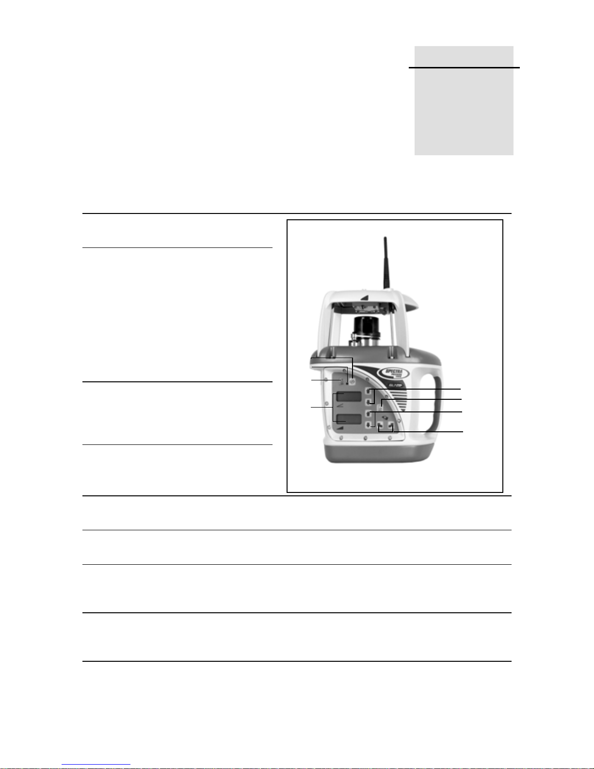
Laser 2.1
1 Power button (π) – turns the
laser on/off.
2 Status LED – shows the
status of various conditions
including an internal,
electronic, or a mechanical
error (solid red), low-battery
(flashing yellow), manual
mode (flashing red), HI alert
(fast flashing red), and out-oflevel (flashing green).
3 Manual button (
the laser from automatic selfleveling
to manual mode.
μ) – changes
3
2
1
4
8
5
6
7
4
1 Axis Up (υ) and Down
(
δ) buttons – change the
grade for the
5 Rotation-Control button (
600, and 900 rpm).
6
2 Axis Up (υ) and Down (δ) buttons (dual-grade laser only) – change the
grade for the
7 Axis-Alignment buttons – rotates the grade axis clockwise (
counterclockwise (
its tripod, with fine adjustment capability.
8 Liquid Crystal Displays (LCDs) – show the percentage of grade, approximate
charge of the batteries, beam’s rotation speed, and axis alignment (if other
than zero). The single-grade laser has one LCD.
1 axis.
ρ) – changes the laser beam’s rotation speed (300,
2 axis.
Λ) or
Ρ). Rotating the grade axis simulates turning the laser on
GL700 Series Laser Transmitter User Guide 3
2 Features and Functions
9
10
11
12
13
14
15
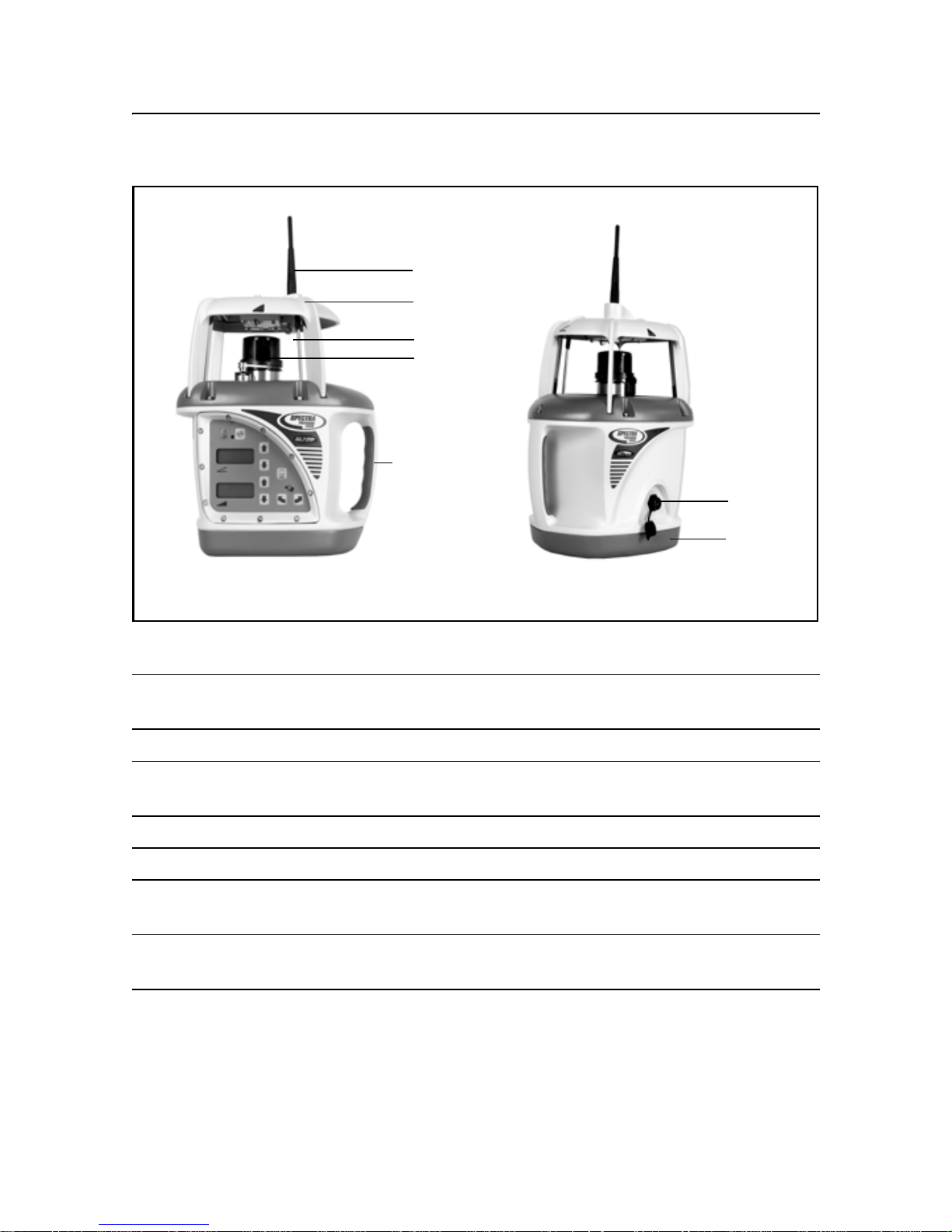
Figure 2.1 Laser transmitter – front and back
9 Antenna (for radio remote-control lasers only) – sends and receives signals
to and from the remote control.
10 Sunshade – protects the lighthouse from the environment.
11 Lighthouse – is the 360° exit window for the laser beam. The lighthouse is
sealed and protects the internal components from the environment.
12 Rotor – contains the rotating laser beam.
13 Handle – allows you to carry the laser easily.
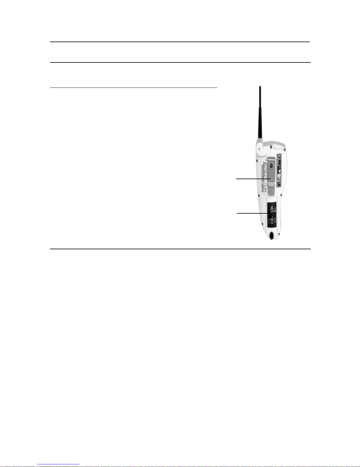
14 Battery Recharging Receptacle – is the 4-pin receptacle that the battery
recharger plugs into. It is also used for external power.
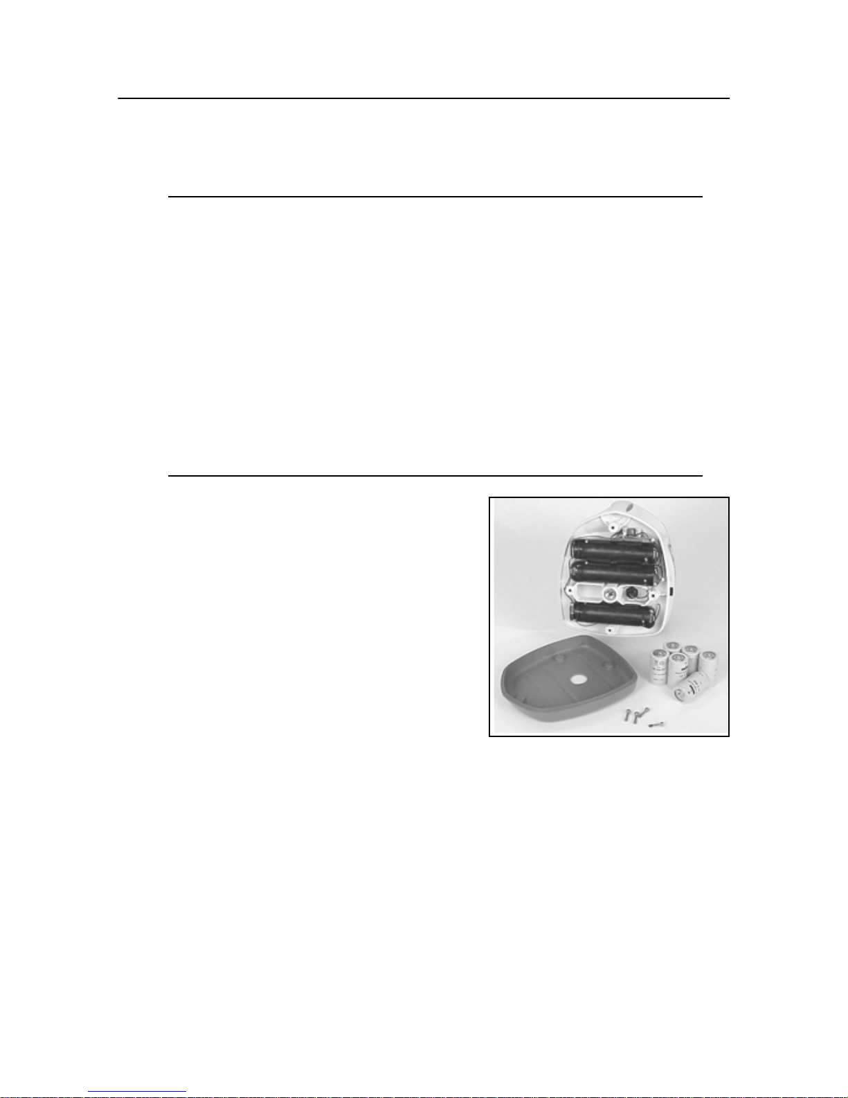
15 Battery Housing – holds six D-cell Ni-Cd, Ni-MH, or backup alkaline
batteries.
4 GL700 Series Laser Transmitter User Guide
17
16
18
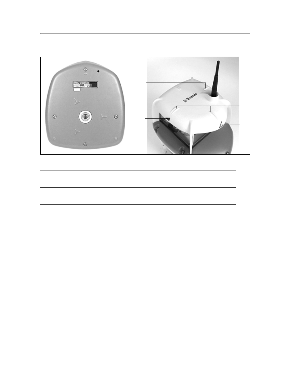
Figure 2.2 Laser transmitter – base and top
Features and Functions 2
17
18
16 5/8-11 Tripod Mount – allows the laser to be connected to a standard
5/8-11 tripod or column mount.
17 Sighting Guides – are used to visually align the laser with a directional
hub or grade stake.
18 Axis-Alignment Marks – correspond with both laser axes and are used
to align the laser in the correct grade direction.
GL700 Series Laser Transmitter User Guide
5
2 Features and Functions
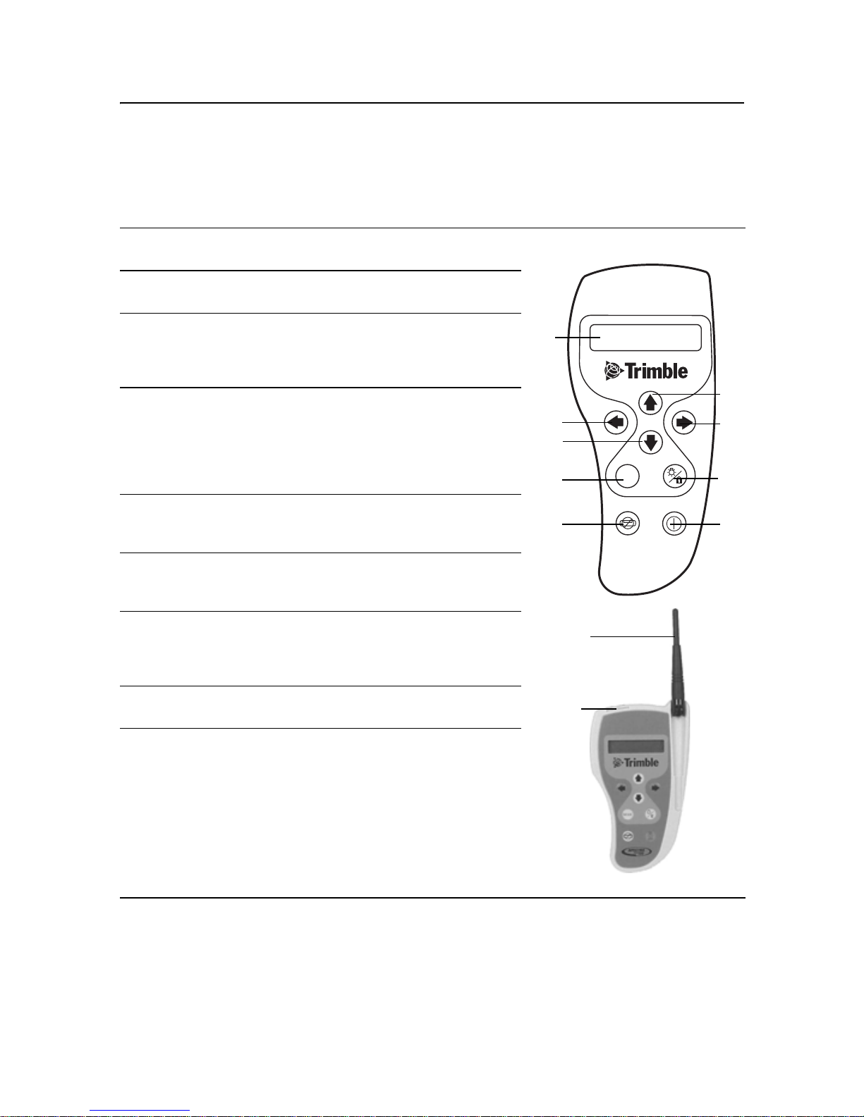
Two-Way Radio Remote Control
(Radio equipped lasers only) 2.2
1
2
3
4
5
6
7
Power/Standby button (π) – turns the remote control
on/off and activates/deactivates standby mode.
Manual button (μ) – changes the laser from
automatic self-leveling to manual mode.
Mode button (Μ) – allows you to choose the laser’s
operational mode, which includes grade change,
automatic axis alignment, grade matching, PlaneLok,
grade reverse, and beam rotation speed.
Up (υ) and Down (δ) buttons – increase/decrease
the grade for the
increase/decrease the laser beam’s rotation speed.
When the laser is in manual mode, these buttons can
also be used to increase/decrease the slope of the
laser beam.
Left (ν) and Right (σ) buttons – increase/decrease
the slope of the
mode.
Liquid Crystal Display (LCD) – shows the mode
messages, beam’s rotation speed, and percentage of
grade.
Enter/Backlight button (ε) – is a multifunctional
button that confirms the selection made from the
laser’s operational mode and activates the
backlighting function.
1 and 2 axes and
2 axis when the laser is in manual
6
4
5
4
3
2
8
MODE
5
7
1
8
9
Antenna – transfers signals between the radio remote
control and laser.
Remote port contacts – transfer operation and
elevation information between the remote control and
the receiver.
6 GL700 Series Laser Transmitter User Guide
9
10 Mounting clip – allows the remote control to be
connected to a grade-rod holster, belt, or a screw on
a wall.
Features and Functions 2
11 Battery Housing
– holds two AA alkaline batteries.
10
11
GL700 Series Laser Transmitter User Guide
7
2 Features and Functions
Accessories 2.3
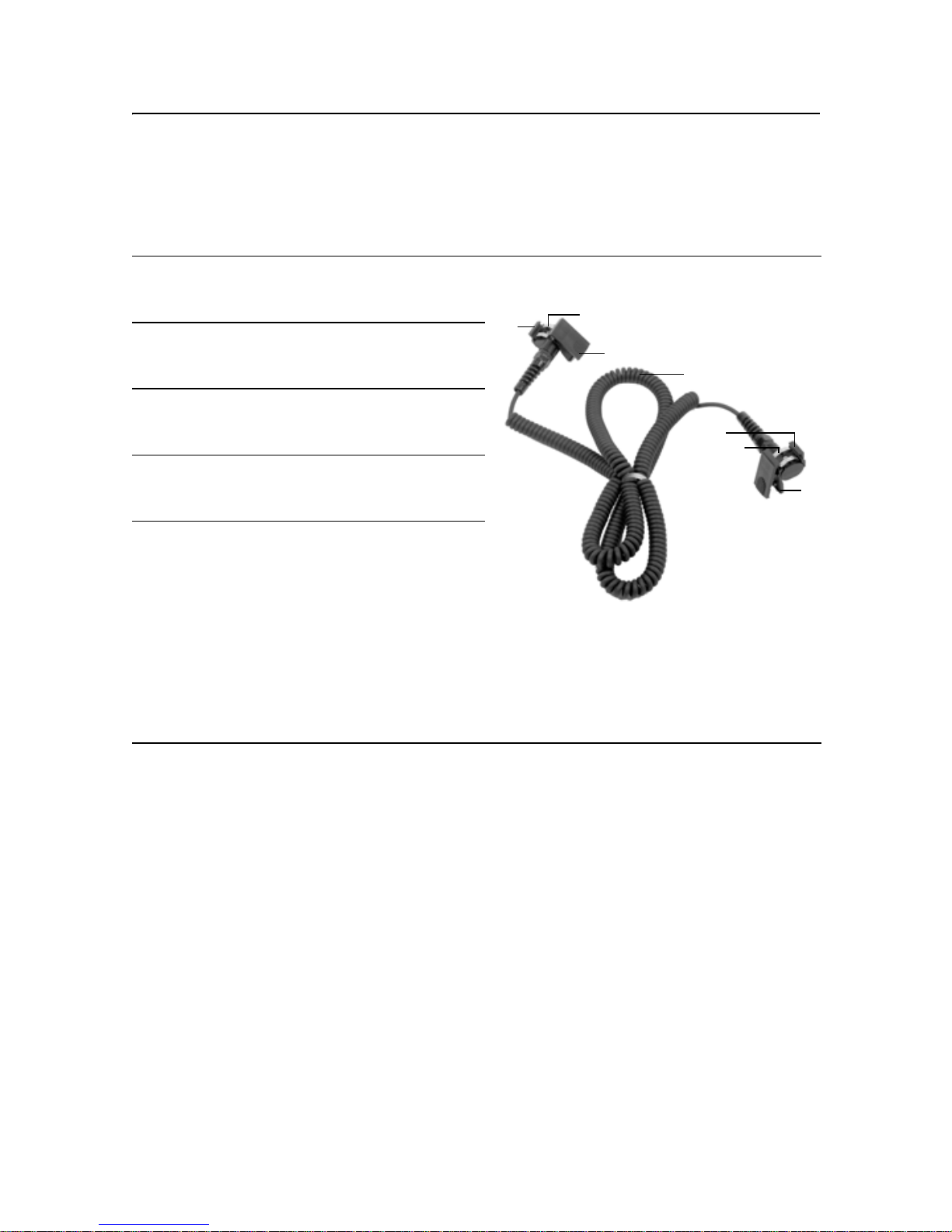
Connector cable 23.1
1 Mounting guides – fit into the mounting
channels on the receiver or the radio
remote control.
2 Contacts – transfer grade-display
signals between the hand-held receiver
and radio remote control.
3 Clamp – connects to the receiver so
signals can be transferred between the
receiver and the radio remote control.
4 4 m (12-ft) cable – transfers signals
between the radio remote control and a
hand-held receiver.
5 Clamp – connects to the radio remote
control so signals can be transferred
between the receiver and the radio
remote control.
To install:
1. Put the small key of the clamp into
the guide on the back of the radio
remote control.
2. Clip the top part of the clamp into the
guide on the front of the radio remote
control.
1
2
3
4
1
2
5
8 GL700 Series Laser Transmitter User Guide
Features and Functions 2
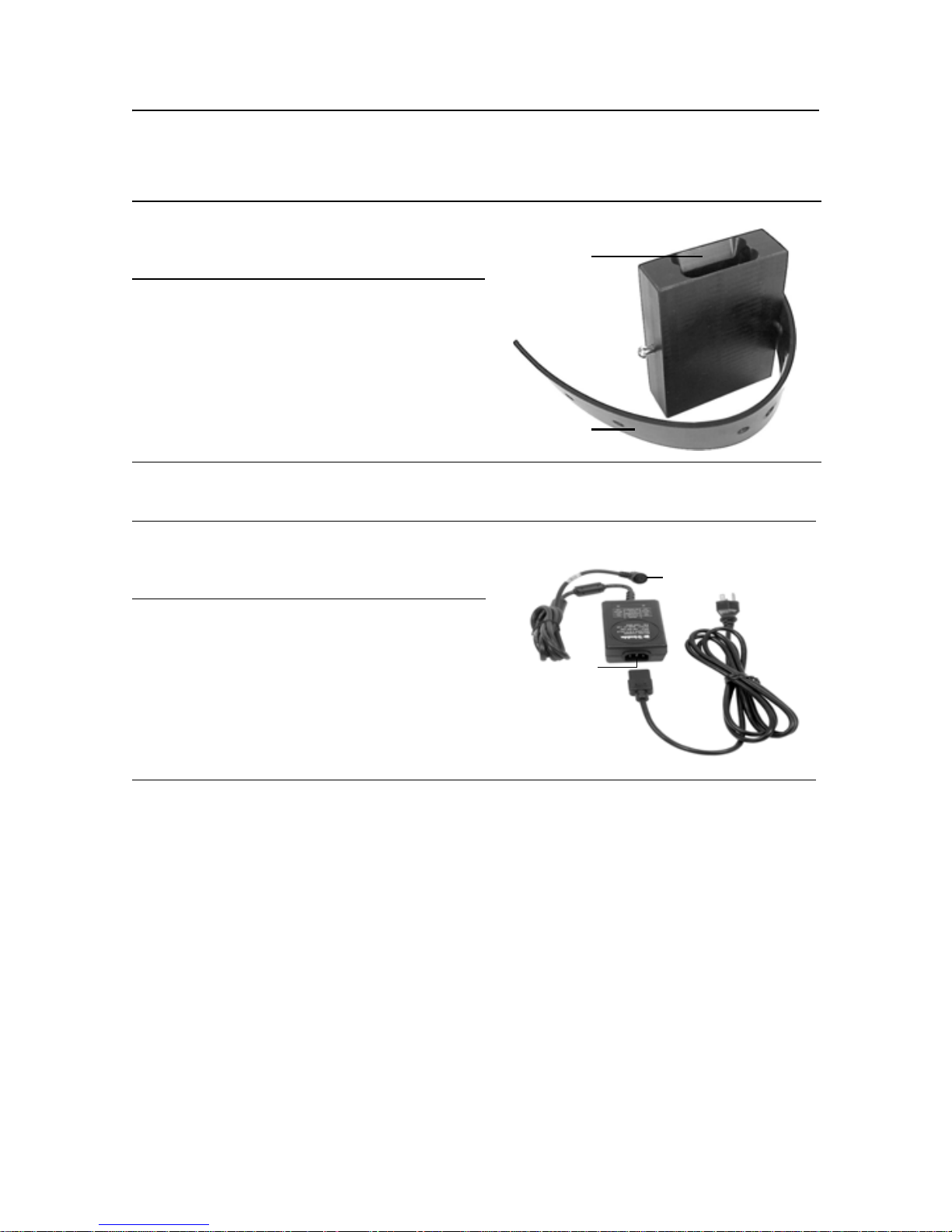
Remote holster 20.1
1 Mounting slot – provides an
opening for the radio remote
control clip to be slipped into.
1
2 Mounting strap – allows the radio
remote control to be connected to
the grade rod for automatic
alignment functions. The holes in
the strap accommodate grade
rods of varying sizes.
2
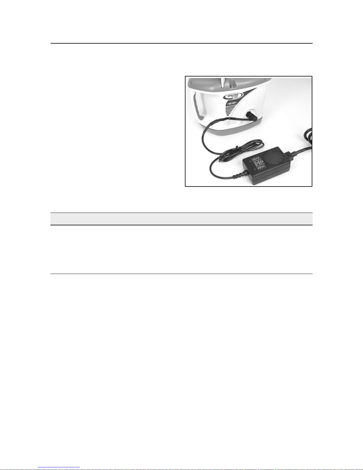
Battery recharger 20.2
1 4-socket plug with retaining collar
– connects to the 4-pin receptacle
on the laser.
1
2 Grounded receptacle connects to
the supplied grounded electrical
power cord.
2
GL700 Series Laser Transmitter User Guide
9

2 Features and Functions
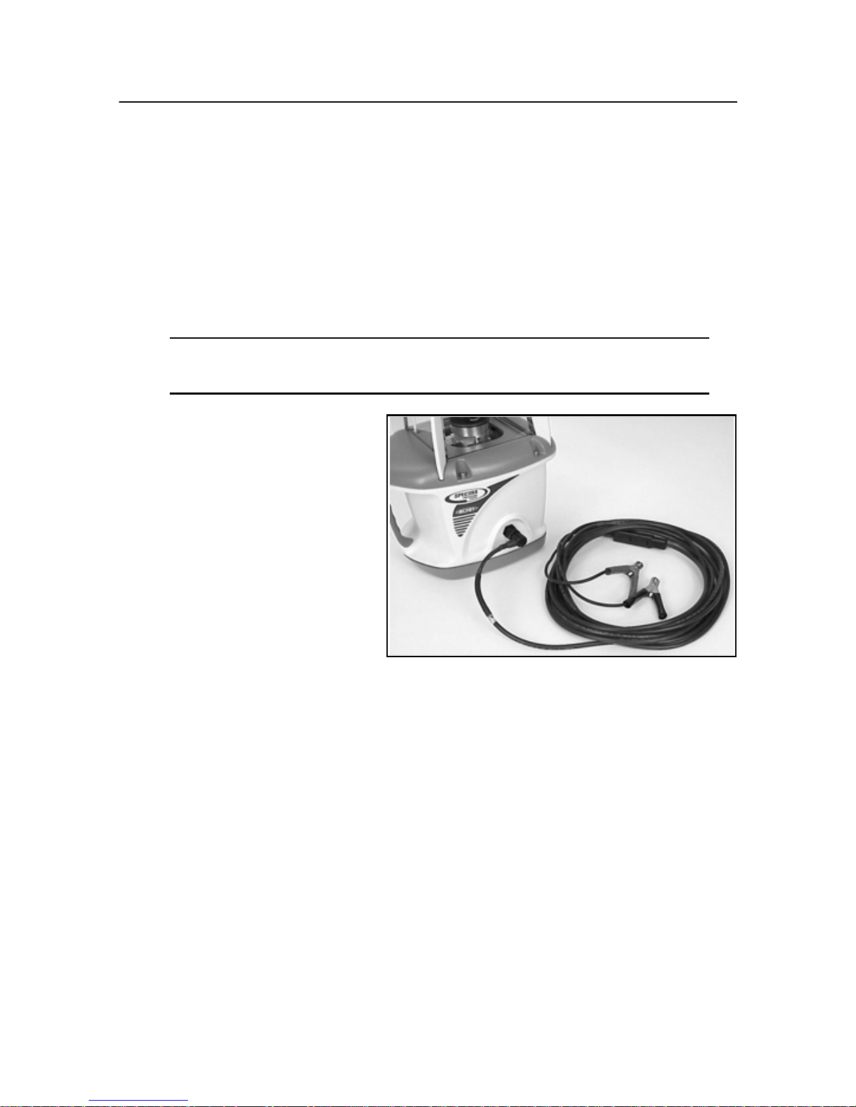
External power cable 20.3
1 Alligator clips (+ and –) – connect
to the positive (+) and negative (–)
terminals on a 12-V DC battery.
2 4-socket plug – connects to the
4-pin receptacle on the laser.
1
2
M100 3½-8 Adapter 20.4
The 3½-8 adapter allows you to connect the laser which has a 5/8-11 threaded
mount to a tripod or other mounting device that has a 3½-8 threaded mount.
M102 Quick-disconnect adapter 20.5
The quick-disconnect adapter allows you to quickly disconnect the laser from the
tripod.
M103 Steep-grade adapter 20.6
The steep-grade adapter allows the internal leveling mechanism of the steep-grade
laser to level the laser at grades greater than 25%.
1243 Sighting scope (GL710 and GL720 only) 20.7
The sighting scope allows manual alignment of the grade axis to a known reference
point. This scope is not required for a radio remote-control laser.
10 GL700 Series Laser Transmitter User Guide

CHAPTER
How to Use the
Laser System 3
3
Powering the Laser – Batteries 3.1
Depending on the laser system configuration that you purchase, the laser is shipped
with either rechargeable nickel-cadmium (Ni-Cd) or nickel/metal-hydride (Ni-MH)
batteries.
Temperature affects battery-charging time. For the best results, charge the batteries
when the ambient temperature is in the range from 10 °C to 40 °C (50 °F to 104 °F).
Charging at a higher temperature may damage the batteries. Charging at a lower
temperature may increase the charge time and decrease the charge capacity,
resulting in loss of performance and shortened battery-life expectancy.
Even if you buy a laser that uses Ni-Cd batteries, you can upgrade to Ni-MH
batteries. The upgrade installation, however, must be performed by an authorized
service center.
Alkaline batteries can also be used as a backup; however, rechargeable batteries
should be reinstalled in the laser as soon as possible.
To let you know when the batteries are getting low, the status LED flashes. When
the status LED flashes yellow, the laser has less than one hour of running time.
When the status LED remains on solid yellow, the batteries have less than five
minutes running time.
After shipment, the batteries may not have enough power to operate the system. Be
sure to recharge the batteries before use. The intelligent recharger maximizes
battery life and reduces the time before battery replacement by precisely controlling
the recharging/discharging cycle and by not overcharging the batteries. The
maximum time to achieve a full charge is six hours.
GL700 Series Laser Transmitter User Guide 11
3 How to Use the Laser System
Recharging the batteries 31.1
Note – Do not recharge alkaline
batteries. Trying to recharge them does
not damage the laser but the batteries do
not recharge.
1. Plug the 4-socket plug into the laser
and tighten the retaining collar.
2. Plug the supplied grounded electrical
power cord into the batteryrecharger.
3. Plug the grounded electrical power
cord into an appropriate outlet.
Note – The recharging status is
indicated on the recharger.
Left LED Right LED Recharging Status
Off Off No connection or no batteries
Off On Recharging is in progress
Flashing Off Recharging is complete
Flashing Flashing Recharging error
Note – The laser will not operate while the batteries are recharging.
Note – Some countries or local areas have regulations regarding the disposal of
rechargeable batteries. Please be sure to follow the regulation in your area.
12 GL700 Series Laser Transmitter User Guide
3 How to Use the Laser System
Installing/removing the batteries 30.1
Warning – The Ni-CD and Ni-MH batteries may contain small amounts of
C
harmful substances.
– Be sure to charge the battery before using it for the first time, and after not
using it for an extended length of time.
– Charge only with specified chargers, according to device manufacturer's
instructions.
– Do not open the battery, dispose of it in a fire, or short circuit it. These
actions may cause the battery to ignite, explode, leak, or get hot, causing
personal injury.
– Dispose in accordance with all applicable federal, state, and local
regulations.
– Keep the battery away from children. If swallowed, do not induce vomiting.
Seek medical attention immediately.
1. Remove the four screws from the battery
housing. Remove the battery-housing
compartment.
2. Install/remove the batteries.
Note – When installing the batteries, be sure
to note the positive (+) and negative (-)
diagram inside of the housing.
Note – The laser has reverse polarity
protection. If the batteries are put in wrong,
no damage occurs to the laser but it does not
work. Allow it one minute to recover after the
batteries have been installed correctly.
3. Put the battery-housing compartment in place and reinstall the four screws.
GL700 Series Laser Transmitter User Guide
13
3 How to Use the Laser System
Powering the Laser – External Cable 3.1
The laser system also includes an external power cable so you can operate the laser
in case the internal batteries become discharged. The internal batteries will not
recharge, however, while you’re using the external power cable.
Connecting/disconnecting the external power cable31.1
Caution – To avoid damaging the laser, make sure the laser is off before
C
1. Connect the alligator clips to a
connecting or disconnecting the external power cable to/from the laser.
12-V DC automotive or
motorcycle battery noting the
correct polarity (red =
positive, black = negative).
2. Plug the 4-socket plug into the
laser and tighten the retaining
collar.
3. To disconnect the external
power cable from the laser,
loosen the retaining collar,
unplug the 4-socket plug from the laser, and remove the alligator clips from the
battery.
14 GL700 Series Laser Transmitter User Guide
3 How to Use the Laser System
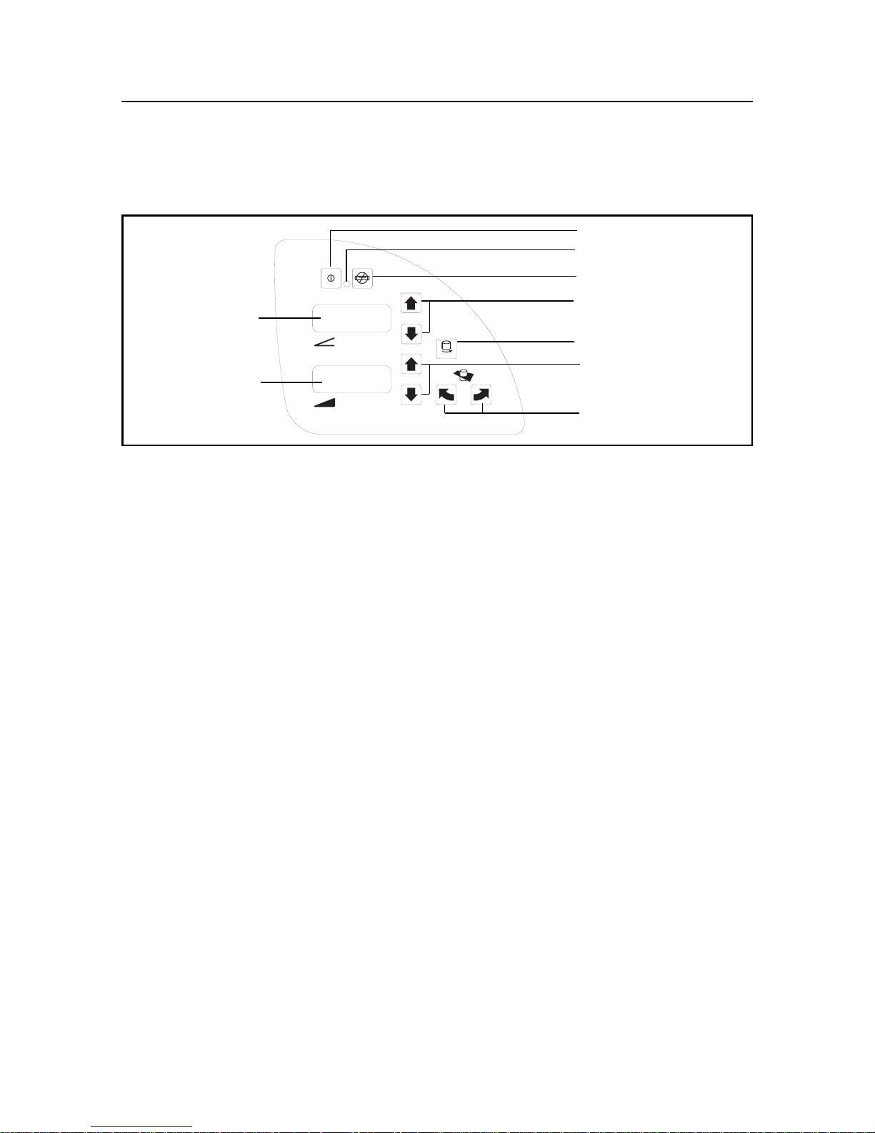
Learning the Basic Laser Functions 3.1
Power
LED
ON
OFF
Manual
1 Up/Down
1 axis LED
Rotation control
RPM
2 axis LED
Figure 3.3 Laser control buttons
2 Up/Down
Axis alignment
Turning on/off the laser 31.1
1. Press the power button (λ) to turn on the laser.
Note – The laser always powers up in the automatic self-leveling mode. If the
laser is out of its self-leveling range and remains out of it for more than 10
minutes, the laser shuts down completely.
Note – When the laser is initially turned on, the LCD shows the approximate
charge of the batteries, the laser beam’s rotation speed, and manual axisalignment position if it’s other than zero. After the LCD shows this information,
the last-entered grade immediately appears in the LCD. The status LED flashes
green to indicate that the laser is self-leveling. After the laser has self-leveled at
the indicated grade, the laser beam rotates and the status LED stops flashing.
Note – After the laser has been level for more than 15 minutes, the HI alert
activates. If the laser is disturbed (tripod bumped, etc.) so that when it re-levels
the laser beam elevation changes by more than 1/8 in. (3.0 mm), the HI alert
shuts down the laser and rotor, and the status LED flashes red two times per
second (twice the manual-mode rate).
2. To turn off the laser, press and hold the power button for three seconds.
GL700 Series Laser Transmitter User Guide
15

3 How to Use the Laser System
Selecting the rotation speed 30.1
The laser has three laser beam rotation speeds—300, 600, and 900 rpm. The
rotation speed can be changed at any time to meet your job-site conditions. Use 600
rpm for held-held receivers and most machine-control systems.
• Repeatedly press and release the rotation-control button (ρ) until the desired
rotation speed appears in the LCD.
Note – The selected rotation speed briefly appears in the LCD. After a few
seconds, the selected percentage of grade appears in the LCD.
Changing the grade value 30.2
The grade value for both axes can be changed using two methods—standard and
quick-change. The standard method is used for entering small changes in the grade
value. The quick-change method is used for setting grade to zero and entering large
changes in the grade value.
Standard method
• Press and hold the up or down button for the axis you want to change until the
correct grade value appears in the laser’s LCD.
Note – The speed of the grade value change increases with the amount of time
the button is held down.
Note – Grade values from -0.500 to 9.999% are displayed in thousandths of a
percent. Grade values greater than 10% are displayed in hundredths of a
percent.
Note – On all models, all changes to the axis-alignment rotation made before
you change the grade value using the standard method are retained.
Quick-change method
Note – The grade value can be quickly set to 0.000% by simultaneously pressing
and holding the up and down buttons for the axis you want to change.
1. Simultaneously press and hold the up and down buttons for the axis you want to
change to set the grade value to 0.000%.
Note – The grade value for the
grade value for the 1 axis increases in 5.00% increments.
2 axis increases in 1.00% increments. The
16 GL700 Series Laser Transmitter User Guide
 Loading...