

Page 1

User Manual
GEOTrac ECM Engine
Module Installation Manual
Version: 1.0
Date: 14-Mar-2016
Page 2
1
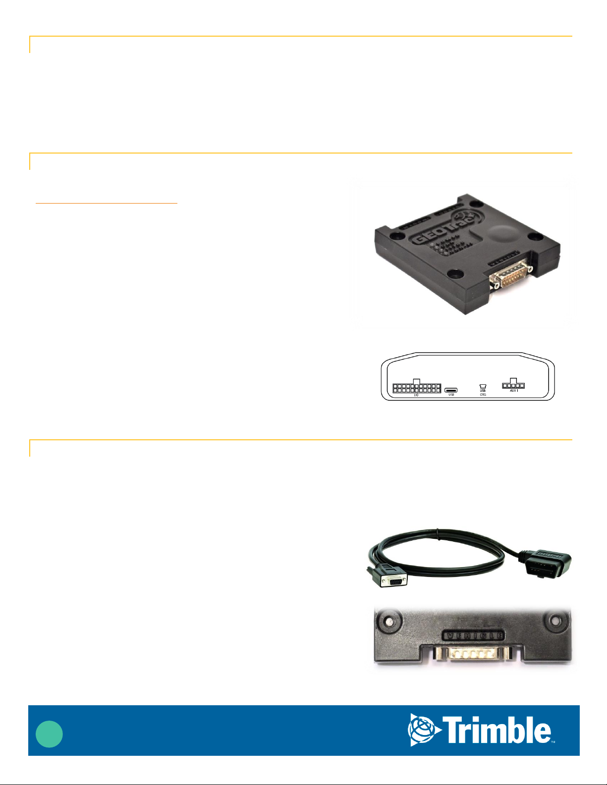
ECM Module
Dual Mode connects to the engine computer and will transmit the data it receives to the client’s database. There is also a
3 axis accelerometer that is used to detect vibration and is also use for collision detection and accident reconstruction.
As with all engine diagnostic devices, there is a need to be programmed for the exact year make and model of vehicle it is
going to be installed into. If not correctly programmed, the device can negatively affect the operation of the vehicle.
Hardware Included
The Dual Mode module can be installed on the GEOTrac 5800
(discontinued but still supported) and the GEOTrac 5530. Contact
sales@geotracinternational.com for more information.
Included with ECM module.
ECM Module
Engine bus splitter cable for J1708 (heavy) vehicles or an
OBDII (light) connector
USB to serial adapter
Null Modem adapter
Serial cable
Included with the GEOTrac 5530 Modem.
GEOTrac 5530
Power cable
Peripheral connection harness
Ethernet cable
Covert Antenna
Installation Procedure
Follow the installation guide and training for the GEOTrac 5800 or GEOTrac 5530 including the Peripheral Harness.
Because of the vibration and collision detection features the ECM must be mounted firmly to either the frame or firewall of
the vehicle it’s being installed into. Each ECM is mounted to a metal plate that will allow you to screw or bolt the ECM
solidly to any flat surface inside the vehicle.
Light duty vehicle connection
The ECM is shipped preprogrammed for the specific year, make
and model of light duty vehicle you are installing. Please be sure
to double check the unit number and programming prior to
install.
The ECM is shipped with a right angle OBDII connector that will
be plugged into engine diagnostics port on the vehicle. This is
usually on the drivers’ side, below the steering wheel and to the
left side.
Once connected to the vehicle port, run the cable to the
mounting location of the ECM module and connect to the port
marked “VEHICLE”. This will the side that has only one port. Be
sure to tighten down the screws to avoid accidental disconnections.
Page 3

2
Heavy duty vehicle connection
Verify that the ECM you have is programmed for the vehicle you’re
installing. There will be a label or a note on the packing slip.
The ECM is shipped with the appropriate 6 pin or 9 pin Deutsch
connector splitter cable. One side is a panel mount configuration
and will replace the connector currently visible underneath and to
the left of the lower dash on the driver’s side.
Unscrew the nut on the stock connector and remove it from its
current location and replace with the panel mount side of the Ycable. Reattach the nut to hold the new connector in place.
Connect the stock connector to the available end and twist the
connector’s collar to lock it into place.
Take the 15 pin DIN connector to the ECM’s mounted location and
connect to the connector on the ECM marked “VEHICLE”. Be sure to
tighten down the screws to avoid accidental disconnection.
ECM Connections
Connect the supplied serial cable to the port on the ECM labeled
“MODEM” and run this cable to the 5530 or 5800.
If a Dual Mode Module is present, you will connect the ECM to the USB port on the front of
the 5530 or the 5800. Connect the USB to Serial adapter to the 5530 or 5800 USB port
The serial cable and the USB to serial adapter will be connected by a Null Modem adapter.
(see diagram on next page for complete install diagram)
Once the ignition is turned ON, check the following LEDs:
a. PICKUPS & NEW HEAVY TRUCKS – make sure the CAN LED is ON
b. OLD HEAVY TRUCKS – make sure the J1708 LED is ON
Note: it might take 30 seconds for CAN/J1708 LEDs to turn ON once the ignition is turned on
Page 4
3
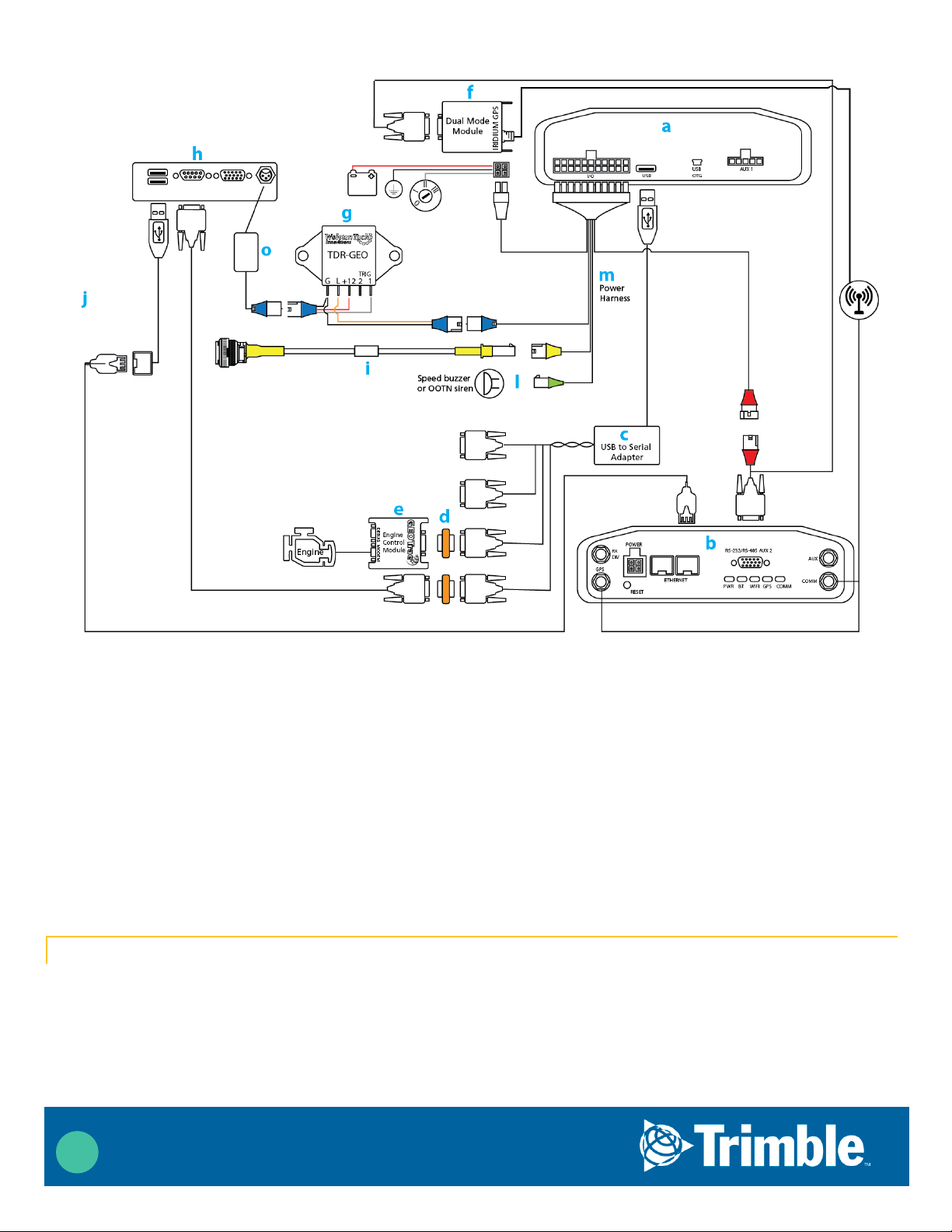
Connections for Wiring Diragram 1:
(a) Rear of modem
(b) Front of modem
(c) USB to Serial quad adapter
(d) Null Modem adapter
(e) ECM module
(f) Dual Mode Module
(g) Timer relay
(h) Tablet Dock connectors
(i) Perf Button
(j) USB connections for Ethernet, speaker and printer
(k) Dual Mode cable
(l) Speed Buzzer or OOTN Siren
(m) Peripheral power harness
(o) DC to DC adatper
Installer Portal
Always use the installer portal to attach the hardware to the unit in the database. Navigate to the Install / Service section
and select Service. Now select the unit number you’re currently working on. If you’re doing a complete new install and the
unit number is not listed, you may have to create a New Unit. For more information on the installer portal, please see the
installer portal guide or online tutorial.
Page 5

4
Once attached, you can now test the hardware. The 5530 and the 5800 will both send a “MIM Restarted” message when
the ECM is detected upon boot up.
Once you see this message, you have successfully installed the GEOTrac ECM. Please follow the instructions and
tutorials for all other devices that are to be installed.
Help
Support: 877.261.2962
Fax: 403.261.2813
Email: info@GEOTracInternational.com
Detailed Supporting Documentation: www.assetcontrolcenter.com (Asset Control Center requires login privileges)
 Loading...