

Page 1

Operator's Manual
Trimble®GCS900 Grade Control System for
Excavators
Version 12.10
Revision A
Part Number 65129-03-ENG
July 2011
11
Page 2

Contact Information
Trimble Engineering and Construction Division
5475 Kellenburger Road
Dayton, Ohio 45424-1099
USA
800-538-7800 (toll free in USA)
+1-937-245-5600 Phone
+1-937-233-9004 Fax
www.trimble.com
Copyright and Trademark s
© 2000–2011, Caterpillar Trimble Control Technologies LLC. All
rights reserved.
Trimble, the Globe & Triangle logo, GCSFlex, CC SFlex, and
SiteVision are trademarks of Trimble Navigation Limited, registered in
the United States and other countries. PROTECTED UNDER U.S.
PATENTS: 5,107,932; 5,375,663; 6,691,437; 7,307,710; 7,246,456;
7,139,662; 5,987,379; 6,324,455; 6,253,160; 4,888,890; 5,235,511;
4,924,374.
SiteNet, CMR and CMR+ are trademarks of Trimble Navigation
Limited.
For STL support, the software uses the STLPort adaptation of the
Moscow Center for SPARC Technology S tandard Template Library.
Copyright © 1994 Hewlett-Packard Company, C opyright © 1996, 97
Silicon Graphics Computer Systems, Inc., Copyright © 1997 Moscow
Center for SPARC Technology, Copyright © 1999, 2000 Boris
Fomitchev.
Microsoft, Windows, and Windows NT are trademarks or registered
trademarks of Microsoft Corporation in the United States and/or other
countries. Wi-Fi is a trademark of the Wi-Fi Alliance, registered in the
United States and other countries. WPA and WPA2 are trademarks of
the Wi-Fi Alliance. Developed under a License of the European Union
and the European Space Agency. Portions of the software are copyright
© 2003 Open Design Alliance. All rights reserved.
All other trademarks are the property of their respective owners.
Release Notice
This is the July2011 release (Revision A) of the GCS900 Grade
Control System for ExcavatorsOperator's Manual, part number 6512903-ENG. It applies to version 12.10 of the GCS900 Grade Control
System software.
The following limited warranties give you specific legal rights. You
may have others, which vary from state/jurisdiction to
state/jurisdiction.
Trimble Navigation Limited
END-USER LICENSE AGREE MENT
IMPORTANT, READ CAREFULLY. THIS END USER LICENSE
AGREEMENT ("AGREEMENT") IS A LEGAL AGREEMENT
BETWEEN YOU AND CATERPILLAR TRIMBLE CONTROL
TECHNOLOGIES LLC ("CTCT") and applies to the computer
software provided by CTCT with the GCS900 or AccuGrade system
(the "Product") purchased by you (whether built into hardware circuitry
as firmware, embedded in flash memory or a PCMCIA card, or stored
on magnetic or other media), or provided as a stand-alone computer
software product, and includes any accompanying printed materials and
any "online" or electronic documentation ("Software"). The Software
also includes any CTCT software (including, without limitation,
upgrades and updates) relating to the Product that is furnished by
Trimble Navigation Limited (“Trimble”) or its dealers (including,
without limitation, CTCT software downloaded from Trimble's or its
dealers' website(s)) unless accompanied by different license terms and
conditions that will govern its use.
BY CLICKING ''YES" OR "I ACCEPT" IN THE ACCEP TANCE
BOX, OR BY INSTALLING, COPYING OR OTHERWISE USING
THE S OFTWARE, YOU AGREE TO BE BOUND BY THE TERMS
OF THIS AGREEMENT. IF YOU DO NOT AGREE TO THE
TERMS OF THIS AGREEMENT, DO NOT USE THE PRODUCT
OR COPY THE SOFTWARE.INSTEAD PROMPTLY RETURN
THE UNUSED SOFTWARE AND ACCOMPANYING P RODUCT
TO THE PLACE FROM WHICH YOU OBTAINED THEM FOR A
FULL REFUND.
1 SOFTWAREP RODUCT LICENSE
1.1 License Grant. Subject to this Agreement, CTCT grants you a
limited, non-exclusive, non-sublicensable right to use one (1) copy of
the Software in a machine-readable form on the Product. Such use is
limited to use with the Product for which it was intended and into
which it was embedded. You may use the installation S oftware from a
computer solely to download the S oftware to one Product. In no event
shall the installation Software be used to download the S oftware onto
more than one Product without securing a separate license. A license
for the Software may not be shared or used concurrently on different
computers or Products.
1.2 Other Rights and Limitations.
(1) You may not copy, modify, make derivative works of, rent, lease,
sell, distribute or transfer the S oftware, in whole or in part, except as
otherwise expressly authorized under this Agreement, and you agree to
use all commercially reasonable efforts to prevent its unauthorized use
and disclosure.
(2) The Software contains valuable trade secrets proprietary to CTCT
and its licensors. You shall not, nor allow any third party to copy,
decompile, disassemble or otherwise reverse engineer the Software, or
attempt to do so, provided, however, that to the extent any applicable
mandatory laws (such as, for example, national laws implementing EC
Directive 91/250 on the Legal Protection of Computer Programs) give
you the right to perform any of the aforementioned activities without
CTCT's consent in order to gain certain information about the
Software for purposes specified in the respective statutes (i.e.,
interoperability), you hereby agree that, before exercising any such
rights, you shall first request such information from C TCT in writing
detailing the purpose for which you need the information. Only if and
after CTCT, at its sole discretion, partly or completely denies your
request, may you exercise such statutory rights.
(3) This S oftware is licensed as a single product. You may not separate
its component parts for use on more than one Product.
(4) You may not rent, lease, or lend, the Software separate from the
Product for which it was intended.
(5) No service bureau work, multiple-user license or time-sharing
arrangement is permitted. For purposes of this Agreement "service
bureau work” shall be deemed to include, without limitation, use of
the Software to process or to generate output data for the benefit of, or
for purposes of rendering services to any third party over the Internet
or other communications network.
(6) You may permanently transfer all of your rights under this
Agreement only as part of a permanent sale or transfer of the Product
for which it was intended, provided you retain no copies, you transfer
all of the Software (including all component parts, the media and
printed materials, any upgrades, and this Agreement) and the recipient
agrees to the terms of this Agreement. If the Software portion is an
upgrade, any transfer must include all prior versions of the Software.
(7) You acknowledge that the Software and underlying technology
may be subject to the export administration regulations of the United
States Government relating to the export of technical data and
products. This Agreement is subject to, and you agree to comply with,
any laws, regulations, orders or other restrictions on the export of the
Software from the United S tates which may be imposed by the United
States Government or agencies thereof.
(8) At the request of CTCT, you agree to cooperate with CTCT to
track the number of Products using Software at your site(s) to ensure
compliance with the license grant and installation restrictions in this
Agreement.
1.3 Termination. You may terminate this Agreement by ceasing all use
of the Software. Without prejudice as to any other rights, CTCT may
terminate this Agreement without notice if you fail to comply with the
2 GCS900GradeControlSystem for Excavators Operator's Manual
Page 3

terms and conditions of this Agreement. In either event, you must
destroy all copies of the Software and all of its component parts, and
provide an affidavit to C TCT stating that you have done the same.
1.4 Copyright. All title and copyrights in and to the Software
(including but not limited to any images, photographs, animations,
video, audio, music, and text incorporated into the Software), the
accompanying printed materials, and any copies of the S oftware are
owned by CTCT and its licensors. You shall not remove, cover or alter
any of CTCTs patent, copyright or trademark notices placed upon,
embedded in or displayed by the Software or on its packaging and
related materials.
1.5 U.S. Government Restricted Rights. The Software is provided with
“RESTRICTED RIGHTS”. Use, duplication, or disclosure by the
United States Government is subject to restrictions as set forth in this
Agreement, and as provided in DFARS 227.7202-1(a) and 227.72023(a)(1995), DFARS 252.227-7013(c)(1)(ii) (OCT 1988), FAR
12.212(a) (1995), FAR 52.227-19, or FAR 52.227-14(ALT III), as
applicable.
2 LIMITED WARRANTY
2.1 Limited Warranty. CTCT warrants that the Software will perform
substantially in accordance with the accompanying written materials
for a period of one (1) year from the date of receipt. This limited
warranty gives you specific legal rights, you may have others, which
vary from state/jurisdiction to state/jurisdiction.
2.2 Customer Remedies. CTCT's and its licensors' entire liability, and
your sole remedy, with respect to the Software shall be either, at
CTCT's option, (a) repair or replacement of the S oftware, or (b) return
of the license fee paid for any Software that does not meet CTCT's
limited warranty. This limited warranty is void if failure of the
Software has resulted from (1) accident, abuse, or misapplication; (2)
alteration or modification of the Software without CTCT’s prior
written authorization; (3) interaction with software or hardware not
supplied by CTCT or Trimble; (4) improper, inadequate or
unauthorized installation, maintenance, or storage of the Software or
Product; or (5) if you violate the terms of this Agreement. Any
replacement Software will be warranted for the remainder of the
original warranty period or thirty (30) days, whichever is longer.
2.3 NO OTHER WARRANTIES. TO THE MAXIMUM EXTENT
PERMITTED BY APPLICABLE LAW, C TCT AND ITS
LICENSORS DISCLAIM ALL OTHER WARRANTIES AND
CONDITIONS, EITHER EXPRESS OR IMPLIED, INCLUDING
BUT NOT LIMITED TO, IMPLIED WARRANTIES AND
CONDITIONS OF MERCHANTABILITY AND FITNESS FOR A
PARTICULAR PURPOSE, TITLE, AND NON INFRINGEMENT
WITH REGARD TO THE SOFTWARE AND THE PROVISION OF
OR FAILURE TO PROVIDE S UPPORT SERVICES. THE ABOVE
LIMITED WARRANTY DOES NOT APPLY TO ERROR
CORRECTIONS, UPDATES OR UPGRADES OF THE
SOFTWARE AFTER EXPIRATION OF THE LIMITED
WARRANTY PERIOD, WHICH ARE PROVIDED "AS IS" AND
WITHOUT WARRANTY. BECAUSE THE S OFTWARE IS
INHERENTLY C OMPLEX AND MAY NOT BE COMPLETELY
FREE OF NONCONFORMITIES, DEFECTS OR ERRORS , YOU
ARE ADVISED TO VERIFY YOUR WORK. CTCT DOES NOT
WARRANT THE RESULTS OBTAINED THROUGH USE OF THE
SOFTWARE, OR THAT THE SOFTWARE WILL OPERATE
ERROR F REE OR UNINTERRUPTED, WILL MEET YOUR
NEEDS OR EXPECTATIONS, OR THAT ALL
NONCONFORMITIES CAN OR WILL BE CORRECTED. TO THE
EXTENT ALLOWED BY APPLICABLE LAW, IMPLIED
WARRANTIES AND CONDITIONS ON THE SOFTWARE ARE
LIMITED TO ONE (1) YEAR. YOU MAY HAVE OTHER LEGAL
RIGHTS WHICH VARY FROM S TATE/JURISDICTION TO
STATE/JURISDICTION.
2.4 LIMITATION OF LIABILITY. CTCT'S ENTIRE LIABILITY
UNDER ANY PROVISION OF THIS AGREEMENT SHALL B E
LIMITED TO THE GREATER OF THE AMOUNT PAID B Y YOU
FOR THE SOFTWARE LICENSE OR U.S. $25.00. TO THE
MAXIMUM EXTENT P ERMITTED BY APPLICABLE LAW, IN
NO EVENT SHALL CTCT OR ITS LICENSORS BE LIABLE F OR
ANY SPECIAL, INCIDENTAL, INDIRECT OR CONSEQUENTIAL
DAMAGES WHATSOEVER (INCLUDING, WITHOUT
LIMITATION, DAMAGES FOR LOSS OF BUSINESS PROFITS,
BUSINESS INTERRUPTION, LOSS OF BUSINESS
INFORMATION, OR ANY OTHER PECUNIARY LOSS) ARISING
OUT OF THE USE OR INABILITY TO USE THE S OFTWARE, OR
THE P ROVISION OF OR FAILURE TO PROVIDE S UPPORT
SERVICES, EVEN IF CTCT HAS BEEN ADVISED OF THE
POSSIBILITY OF SUCH DAMAGES. BECAUSE SOME STATES
AND JURISDICTIONS DO NOT ALLOW THE EXCLUSION OR
LIMITATION OF LIABILITY FOR CONSEQUENTIAL OR
INCIDENTAL DAMAGES, THE ABOVE LIMITATION MAY NOT
APPLY TO YOU.
3 GENERAL
3.1 This Agreement shall be governed by the laws of the State of Ohio
and applicable United S tates Federal law without reference to “conflict
of laws" principles or provisions. The United Nations Convention on
Contracts for the International Sale of Goods will not apply to this
Agreement. Jurisdiction and venue of any dispute or court action
arising from or related to this Agreement or the Software shall lie
exclusively in or be transferred to the courts of the Montgomery
County, Ohio, and/or the United States District Court for Ohio. You
hereby consent and agree not to contest, such jurisdiction, venue and
governing law.
3.2 Notwithstanding Section 3.1, if you acquired the Product in
Canada, this Agreement is governed by the laws of the Province of
Ontario, Canada. In such case each of the parties to this Agreement
irrevocably attorns to the jurisdiction of the courts of the P rovince of
Ontario and further agrees to commence any litigation that may arise
under this Agreement in the courts located in the Judicial District of
York, Province of Ontario.
3.3 Official Language. The official language of this Agreement and of
any documents relating thereto is English. For purposes of
interpretation, or in the event of a conflict between English and
versions of this Agreement or related documents in any other language,
the English language version shall be controlling.
3.4 CTCT reserves all rights not expressly granted by this Agreement.
2011©, Caterpillar Trimble Control Technologies LLC. All Rights
Reserved.
Product Warranty Information
For applicable product warranty information, please refer to the
Warranty Card included with this product, or consult your dealer.
Notices
Class B Statement – Notice to Users. This equipment has been tested
and found to comply with the limits for a Class B digital device,
pursuant to Part 15 of the FCC rules. These limits are designed to
provide reasonable protection against harmful interference in a
residential installation. This equipment generates, uses, and can radiate
radio frequency energy and, if not installed and used in accordance
with the instructions, may cause harmful interference to radio
communication. However, there is no guarantee that interference will
not occur in a particular installation. If this equipment does cause
harmful interference to radio or television reception, which can be
determined by turning the equipment off and on, the user is
encouraged to try to correct the interference by one or more of the
following measures:
- Reorient or relocate the receiving antenna.
- Increase the separation between the equipment and the receiver.
- Connect the equipment into an outlet on a circuit different from
that to which the receiver is connected.
- Consult the dealer or an experienced radio/TV technician for help.
GCS900GradeControlSystem for Excavators Operator's Manual 3
Page 4

Changes and modifications not expressly approved by the
manufacturer or registrant of this equipment can void your authority to
operate this equipment under F ederal Communications Commission
rules.
Canada
This digital apparatus does not exceed the Class B limits for radio
noise emissions from digital apparatus as set out in the radio
interference regulations of the C anadian Department of
Communications.
Le présent appareil numérique n’émet pas de bruits radioélectriques
dépassant les limites applicables aux appareils numériques de Classe B
prescrites dans le règlement sur le brouillage radioélectrique édicté par
le Ministère des Communications du Canada.
Europe
This product has been tested and found to comply with the
requirements for a Class B device pursuant to European
Council Directive 89/336/EEC on EMC, thereby satisfying
the requirements for CE Marking and sale within the European
Economic Area (EEA). Contains Infineon radio module ROK 104001.
These requirements are designed to provide reasonable protection
against harmful interference when the equipment is operated in a
residential or commercial environment.
Australia and New Zealand
This product conforms with the regulatory requirements of
the Australian Communications Authority (ACA) EMC
framework, thus satisfying the requirements for C-Tick
Marking and sale within Australia and New Zealand.
Taiwa n – Battery Rec yc ling Requirements
The product contains a removable Lithium-ion battery.
Taiwanese regulations require that waste batteries are recycled.
Notice to Our European Union Customers
For product recycling instructions and more information, please go to
www.trimble.com/environment/summary.html.
Recycling in Europe: To recycle Trimble WEEE (Waste
Electrical and Electronic Equipment, products that run on
electrical power.), Call + 31 497 53 24 30, and ask for the
"WEEE Associate". Or, mail a request for recycling instructions
to:
Trimble Europe BV
c/o Menlo Worldwide Logistics
Meerheide 45
5521 DZ Eersel, NL
4 GCS900GradeControlSystem for Excavators Operator's Manual
Page 5
Safety Information
Most accidents that involve product operation, maintenance and repair are caused
by failure to observe basic safety rules or precautions. An accident can often be
avoided by recognizing potentially hazardous situations before an accident occurs.
A person must be alert to potential hazards. This person should also have the
necessary training, skills and tools to perform these functions properly.
Improper operation, lubrication, maintenance or repair of this product can be
dangerous and could result in injury or death.
Do not operate or perform any lubrication, maintenance or repair on this product,
until you have read and understood the operation, lubrication, maintenance and
repair information.
Safety precautions and warnings are provided in this manual and on the product. If
these hazard warnings are not heeded, bodily injury or death could occur to you or
to other persons.
The hazards are identified by the “Safety Alert Symbol” and followed by a “Signal
Word” such as “DANGER”, “WARNING” or “CAUTION”. The Safety Alert
“WARNING” label is shown below.
WARNING — This alert warns of a potential hazard which, if not avoided, can cause severe
injury.
The meaning of this safety alert symbol is as follows:
Attention! Become Alert! Your Safety is Involved.
The message that appears under the warning explains the hazard and can be either
written or pictorially presented.
Operations that may cause product damage are identified by “NOTICE” labels on
the product and in this publication.
Trimble® cannot anticipate every possible circumstance that might involve a
potential hazard. The warnings in this publication and on the product are, therefore,
not all inclusive. If a tool, procedure, work method or operating technique that is not
specifically recommended by Trimble is used, you must satisfy yourself that it is
safe for you and for others. You should also ensure that the product will not be
damaged or be made unsafe by the operation, lubrication, maintenance or repair
procedures that you choose.
The information, specifications, and illustrations in this publication are on the basis
of information that was available at the time that the publication was written. The
specifications, torques, pressures, measurements, adjustments, illustrations, and
other items can change at any time. These changes can affect the service that is
GCS900GradeControlSystem for Excavators Operator's Manual 5
Page 6

Safety Information
Safety (Laser)
given to the product. Obtain the complete and most current information before you
start any job. Dealers have the most current information available.
The IEC and the United States Government Center of Devices for Radiology Health
(CDRH) has classified this laser as a Class II laser product. The maximum radiant
power output of this laser is less than 5 milliwatts.
Refer to the operator's manual of the laser transmitter for installation and operating
instructions.
The laser that is supplied with the GCS900 - Laser System complies with all
applicable portions of “Title 21” of the “Code of Federal Regulations, Department
of Health and Human Services, Food and Drug Administration, Federal Register,
Volume 50, Number 161, 20 August 1985”.
This laser complies with “OSHA Standards Act, Section 1518.54” for use without
eye protection. Eye protection is not required or recommended. The following
safetyrules should be observed:
l Never look into a laser beam or point the beam into the eyes of other people.
Set the laser at a height that prevents the beam from flashing directly into
people's eyes.
l Do not remove any warning signs from the laser.
l Use of this product by personnel that are not trained on this product may result
in exposure to hazardous laser light.
l If initial service requires the removal of the outer protective cover, removal of
the cover must be performed by trained personnel.
Crushing Prevention and Cutting Prevention
Support the equipment properly when you work beneath the equipment. Do not
depend on the hydraulic cylinders to hold up the equipment. An attachment can fall
if a control is moved, or if a hydraulic line breaks.
Unless you are instructed otherwise, never attempt adjustments while the machine
is moving. Also, never attempt adjustments while the engine is running.
Whenever there are attachment control linkages, the clearance in the linkage area
will increase or the clearance in the linkage area will decrease with movement of
the attachment. Stay clear of all rotating and moving parts.
Keep objects away from moving fan blades. The fan blade will throw objects or cut
objects. Do not use a kinked wire cable or a frayed wire cable.
Wear gloves when you handle wire cable. When you strike a retainer pin with
force, the retainer pin can fly out. The loose retainer pin can injure personnel. Make
sure that the area is clear of people when you strike a retainer pin.
6 GCS900GradeControlSystem for Excavators Operator's Manual
Page 7

In order to avoid injury to your eyes, wear protective glasses when you strike a
retainer pin.
Chips or other debris can fly off objects when you strike the objects. Make sure that
no one can be injured by flying debris before striking any object.
Operation
Clear all personnel from the machine and from the area.
Clear all obstacles from the machine's path. Beware of hazards (wires, ditches,
etc).
Be sure that all windows are clean.
Secure the doors and the windows in the open position or in the shut position.
Adjust the rear mirrors (if equipped) for the best visibility close to the machine.
Make sure that the horn, the travel alarm (if equipped), and all other warning
devices are working properly.
Fasten the seat belt securely.
Safety Information
Warm up the engine and the hydraulic oil before operating the machine.
Only operate the machine while you are in a seat.
The seat belt must be fastened while you operate the machine. Only operate the
controls while the engine is running.
While you operate the machine slowly in an open area, check for proper operation
of all controls and all protective devices. Before you move the machine, you must
make sure that no one will be endangered.
Do not allow riders on the machine unless the machine has the following equipment:
l Additional seat
l Additional seat belt
l Rollover Protective Structure (ROPS)
Note any needed repairs during machine operation. Report any needed repairs.
Avoid any conditions that can lead to tipping the machine. The machine can tip
when you work on hills, on banks and on slopes. Also, the machine can tip when
you cross ditches, ridges or other unexpected obstructions.
Avoid operating the machine across the slope. When possible, operate the machine
up the slopes and down the slopes.
Maintain control of the machine.
Do not overload the machine beyond the machine capacity.
Be sure that the hitches and the towing devices are adequate.
Never straddle a wire cable. Never allow other personnel to straddle a wire cable.
GCS900GradeControlSystem for Excavators Operator's Manual 7
Page 8

Safety Information
Warnings
Before you maneuver the machine, make sure that no personnel are between the
machine and the trailing equipment.
Always keep the Rollover Protective Structure (ROPS) installed during machine
operation.
Monitor the location of components that are mounted to the blade. Ensure that the
components do not come into contact with other parts of the machine during
operation.
WARNING — When replacement parts are required for this product Trimble recommends
using Trimble replacement parts or parts with equivalent specifications including, but not
limited to, physical dimensions, type, strength and material. Failure to heed this warning can
lead to premature failures, product damage, personal injury or death.
WARNING — If you create a ramp or other work platform that is too steep, machines and
vehicles using the ramp or platform could become difficult to control. This could result in
harm to the operator, to others, or damage to the machine. To ensure your safety and the
safety of others, find out what the maximum slope for your site is and make sure you do not
exceed it.
WARNING — Do not operate or work on this machine unless you have read and understand
the instructions and warnings in the system manual. Failure to follow the instructions or heed
warnings could result in injury or death. Contact your dealer for replacement manuals.
Proper care is your responsibility.
WARNING — If the machine’s direction is locked, for example if it is locked in the forward
direction, the distance to avoidance zones will be calculated incorrectly when you are driving
in the opposite direction, resulting in unreliable avoidance zone warnings. Entering an
avoidance zone could cause personal injury or damage to the machine. Always be aware of
nearby avoidance zones when operating a machine with direction lock on.
WARNING — In order to prevent personal injury during installation and removal of a GPS
receiver or a UTS target, use an approved access system in order to reach the mounting
locations of the GPS receiver or UTS target at the top of the mast.
WARNING — Do not stare into the laser beam when the laser transmitter is operating. For
more information, refer to the documentation that came with your laser.
WARNING — Falling Hazard. Do not climb onto the machine in order to access the GPS
receiver or UTS target. Climbing on the machine could result in a fall which could cause
serious injury or death. Use the raise and lower mechanism to access the GPS receiver or
UTS target for all required maintenance and service.
8 GCS900GradeControlSystem for Excavators Operator's Manual
Page 9

Contents
Safety Information 5
1 About This Manual 13
1.1 Scope and audience 14
1.2 Trimble training classes and technical assistance 14
1.3 To learn more about Trimble 14
1.4 Your comments 14
2 Using the Control Box and Lightbars 15
2.1 Introduction 16
2.2 Control box basics 16
2.2.1 Power key 17
2.2.2 System memory and the USB flash drive 17
2.2.3 Transferring data to and from the control box 18
2.3 Working with control box information 21
2.3.1 Working with menus and dialogs 22
2.3.2 Working with guidance screens 27
2.3.3 Guidance views 32
2.4 Understanding lightbar information 34
2.4.1 External lightbars 34
2.4.2 Internal lightbars 35
2.4.3 3D excavator lightbar behaviour 35
2.4.4 2D excavator lightbar behavior 38
2.5 3D remote switch 39
2.6 System beeper 39
3 Preparing to Work 41
3.1 Introduction 42
3.2 Power up checks 42
3.2.1 Lightbar power up 42
3.2.2 Control box power up 43
3.3 Software option keys 44
3.3.1 Option key structure 44
3.3.2 Software support 44
3.3.3 Troubleshooting option keys 44
3.4 Work preparation checks 45
3.4.1 Machine settings 46
3.4.2 Switching guidance modes 47
3.4.3 Main screen views 47
3.4.4 Display brightness 49
GCS900GradeControlSystem for Excavators Operator's Manual 9
Page 10

Contents
3.4.5 Keypad backlight brightness 49
3.4.6 Lightbar brightness 50
3.4.7 Display settings 50
3.4.8 Lightbar tolerances 51
3.4.9 Set depth and slope increment values 53
3.4.10 Checking bucket wear 53
3.5 Configuring the machine radio 54
3.6 Wi-Fi networking 57
3.6.1 About cellular modems 57
3.6.2 About Wi-Fi networking 57
3.6.3 SNRx20 radio modem status indicators 57
3.6.4 Managing Wi-Fi networks 58
3.6.5 Connecting to a Wi-Fi network 58
3.7 Exchanging files with a Connected Community filespace 59
3.7.1 Initiating Connected Community file exchange from the machine 59
3.7.2 Connected Community file synchronization 60
3.7.3 Troubleshooting Connected Community file exchange 60
3.8 Selecting an excavator bucket 61
3.9 Selecting a 3D vertical guidance method 62
3.10 Selecting a Depth and Slope vertical guidance method 63
4 Using 2D Depth And Slope Guidance in the Field 65
4.1 Introduction 66
4.2 Setting the focus point 66
4.3 Selecting or creating a guidance model 66
4.3.1 Selecting a vertical guidance method 67
4.3.2 Depth and Slope system softkeys 68
4.3.3 Depth and slope models 68
4.3.4 Depth dual slope models 71
4.3.5 Profile models 75
4.4 Establishing an elevation reference 77
4.4.1 Using the bucket focus as the reference elevation 78
4.4.2 Using a laser plane as the reference elevation 78
4.5 Working with Depth and Slope guidance 79
4.5.1 Transferring a benchmark reference elevation 80
4.5.2 Using the bucket position to measure site features 82
5 Using 3D Guidance in the Field 85
5.1 Introduction 86
5.2 Preparing 3D sensors 86
5.2.1 Starting the UTS system 87
5.2.2 Benching a UTS target 89
5.2.3 Setting the UTS accuracy level 90
5.2.4 Initializing single-3D excavator orientation 91
5.2.5 Setting GPS accuracy mode 92
10 GCS900GradeControlSystem for Excavators Operator's Manual
Page 11

Conttents
5.2.6 GPS geoid grid support 92
5.3 Checking 3D cutting edge guidance 93
5.4 Loading or creating a design 94
5.4.1 Loading a design 94
5.4.2 Creating a design 97
5.5 Working with 3D guidance 103
5.5.1 Setting the working surface lift and/or vertical offset 104
5.5.2 Selecting horizontal alignment 105
5.5.3 Selecting focus for horizontal guidance 107
5.5.4 Setting horizontal offset 108
5.5.5 3D remote switch support 108
5.5.6 Reacquiring UTS lock 109
5.5.7 Re-initializing orientation after moving the machine 109
5.5.8 Clearing the UTS benched elevation 109
5.5.9 Turning off UTS guidance 110
6 Using Mapping/Recording in the Field 111
6.1 Introduction 112
6.2 Automatic mapping 112
6.2.1 Fixed mapping rules 112
6.2.2 Machine mapping rules 112
6.3 Loading or creating a map 113
6.3.1 Creating a map file 113
6.3.2 Loading a map file 114
6.4 Configuring Mapping/Recording 114
6.5 Using Mapping/Recording 115
6.5.1 Mapping/Recording states 115
6.5.2 Plan view mapping types 116
6.6 Minimum height mapping 117
6.7 Point recording 117
7 Troubleshooting in the Field 119
7.1 Introduction 120
7.2 General troubleshooting 120
7.3 Running system diagnostics 120
7.3.1 UTS diagnostics 122
7.3.2 GPS diagnostics and satellite monitoring 126
7.4 Troubleshooting flashing warning messages 130
7.4.1 General warning messages 131
7.4.2 UTS warning messages 132
7.4.3 GPS warning messages 134
7.4.4 Excavator warning messages 137
7.5 Troubleshooting error messages 138
7.5.1 Software support option errors 138
7.5.2 Avoidance zone warnings 139
GCS900GradeControlSystem for Excavators Operator's Manual 11
Page 12

Contents
7.5.3 Other selected error messages 139
7.6 Troubleshooting system components 145
7.6.1 External lightbar system status indicators 145
7.6.2 GPS receiver status indicators 146
7.6.3 SNRx10 data radio status indicators 147
7.6.4 SNR900, SNR450, and SiteNet 450 data radio indicators 148
7.6.5 MT900 machine target status indicators 148
7.6.6 Excavator arm sensor error indication 149
7.7 Troubleshooting UTS systems 149
7.8 Troubleshooting GPS systems 151
7.9 Before you contact your dealer 152
Index 155
12 GCS900GradeControlSystem for Excavators Operator's Manual
Page 13

C H A P T E R
1
1About This Manual
In this chapter:
n Scope and audience
n Trimble training classes and
technical assistance
n To learn more about Trimble
n Your comments
Welcome to the GCS900 Grade Control System
for Excavators Operator's Manual. This manual
provides procedural information for the day to
day operation of the system. The system is
designed specifically for earthmoving
equipment in the construction industry.
GCS900GradeControlSystem for Excavators Operator's Manual 13
Page 14

1 About This Manual
1.1 Scope and audience
This manual is intended for personnel who operate the system, including:
l Machine operators
l Dealers
l Installation technicians
l Site supervisors
This manual describes how to use the standard features of the system. To learn
about the underlying concepts of the system, refer to the Trimble GCS900 Grade
Control System Reference Manual.
For information on how to use features not described in this manual, refer to the
Trimble GCS900 Grade Control System Site Supervisor’s Manual.
Even if you have used other machine guidance systems before, Trimble
recommends that you spend some time reading this manual to learn about the
special features of this product.
Trimble manuals that are related to this product are available in PDF format on the
GCS900 Grade Control System release media. To view or print the manuals, use
Adobe Reader (provided on the media). Utilities that do not have an accompanying
manual have integrated Help.
1.2 Trimble training classes and technical assistance
Contact your dealer for:
l Technical support, information notes, and other technical notes
l Information about:
the support agreement contracts for software and firmware
extended warranty programs for hardware
training classes
1.3 To learn more about Trimble
For an interactive look at Trimble, go to www.trimble.com.
1.4 Your comments
Your feedback about the supporting documentation helps us to improve it with each
revision. Email your comments to ReaderFeedback@trimble.com.
14 GCS900GradeControlSystem for Excavators Operator's Manual
Page 15

C H A P T E R
2
2Using the Control Box and Lightbars
In this chapter:
n Control box basics
n Working with control box
information
n Understanding lightbar
information
n 3D remote switch
n System beeper
As you work with the GCS900 Grade Control
System, you need to set up and control the
guidance system and understand the guidance
information the system provides.
GCS900GradeControlSystem for Excavators Operator's Manual 15
Page 16

2 Usingthe ControlBox andLightbars
2.1 Introduction
The control box is a computer that runs the system software. You control the
guidance system with, and are given guidance information by, the following system
components:
l the control box and lightbars
l the remote switches, if installed
l the audible alarm, or beeper
This chapter describes, in general terms, how these components are used.
For more information on these components, refer to the GCS900 Grade Control
System Reference Manual.
2.2 Control box basics
The control box has a color LCD screen to display guidance and other information,
and push button controls to operate the system. In addition, the control box has
internal lightbars, and a USB flash drive port for loading and saving machine and
display configuration data, and for loading and saving data. See Figure 2.1 and the
following table that describes the items in the figure.
Power button
1
Next key
4
Zoom-out key
7
OK key
a
Figure 2.1 The control box
16 GCS900GradeControlSystem for Excavators Operator's Manual
2
5
8
b
Softkey label area
Zoom-in key
Escape key
USB flash drive port
Softkeys
3
Beeper
6
Arrow keys
9
Menu key
c
Page 17

Description Function
LCD screen Displays guidance information
UsingtheControl Box andLightbars 2
Softkey labels See
Softkeys See
Zoom-in key
Zoom-out key
Next key
Menu key
USB flash drive port See
Arrow keys
+
-
N
M
( )
Zoom in on the machine
Zoom out from the machine
View the next guidance screen or select the next field in a dialog
View the
Pan a guidance view, select an item in a list, or enter data in a field
[ ]
OK key
Escape key
Power key
Beeper
\
=
P
Save changes made in a dialog, and exit the dialog
Exit from a dialog without saving changes, or exit from a menu
See
See 2.6 System beeper
2.3.1 Working with menus and dialogs
2.3.1 Working with menus and dialogs
Setup Menu – Configuration
2.2.2 System memory and the USB flash drive
2.2.1 Power key
dialog
2.2.1 Power key
The P key turns the control box on and off.
To turn on the control box and the system, press P. After a brief pause, an
opening screen appears.
Note – If the system reports that there are upgrade files or other system files on the
control box, or that the operating system is out of date, contact your site supervisor
immediately.
To turn off the control box and the system, press and hold P for two to three
seconds until the control box shuts down. (This delay reduces the risk of you turning
off the power accidentally.) You can turn off the system from any screen or dialog.
2.2.2 System memory and the USB flash drive
Files and data are stored on the control box in an area known as system memory.
The files and data in system memory are used by the system and there is only
limited Site Supervisor access via the control box.
GCS900GradeControlSystem for Excavators Operator's Manual 17
Page 18
2 Usingthe ControlBox andLightbars
To access the files and data in system memory, they need to be transferred from the
control box onto a USB flash drive. The files and data on the USB flash drive can
then be directly accessed from a laptop, an office computer, or SiteVision Office
software.
Note – When you insert a USB flash drive into the control box, system operation is
temporarily disabled. System operation resumes when the USB flash drive is
removed.
The USB flash drive folder structure is:
l At the root directory level is a “Machine Control Data” folder.
l Within the “Machine Control Data” folder are machine specific folders based
on machine names, which contain machine specific data. For example, a
“HEX” folder for Hydraulic Excavator.
Note – If folders do not exist when files are transferred to the USB flash drive, the
system will create them.
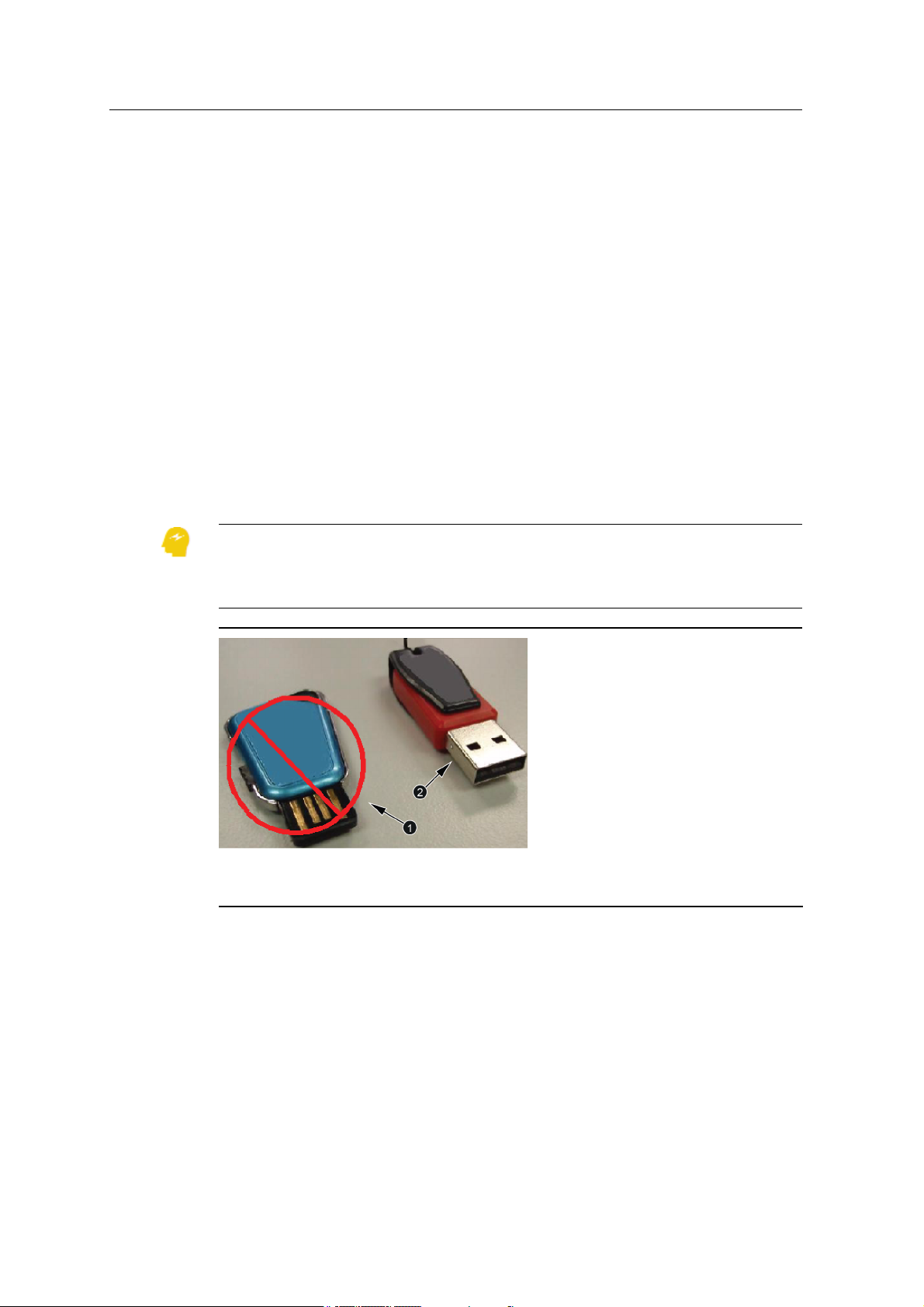
ATTENTION — It is recommended to always use a USB flash drive with a metal surround on
the connector. When using a USB flash drive with no metal surround on the connector, the
drive can be inserted upside down, and due to the lack of the metal part of the connector,
contact can be broken and the file transfer process can be interrupted. See Figure 2.2.
No metal surround on the connector (NOT
1
recommended)
Figure 2.2 USB flash drive connector examples
2.2.3 Transferring data to and from the control box
1. Start the control box.
2. Insert the USB flash drive into to the control box USB port. The File Transfer
18 GCS900GradeControlSystem for Excavators Operator's Manual
Metal surround on the connector
2
(recommended)
Page 19
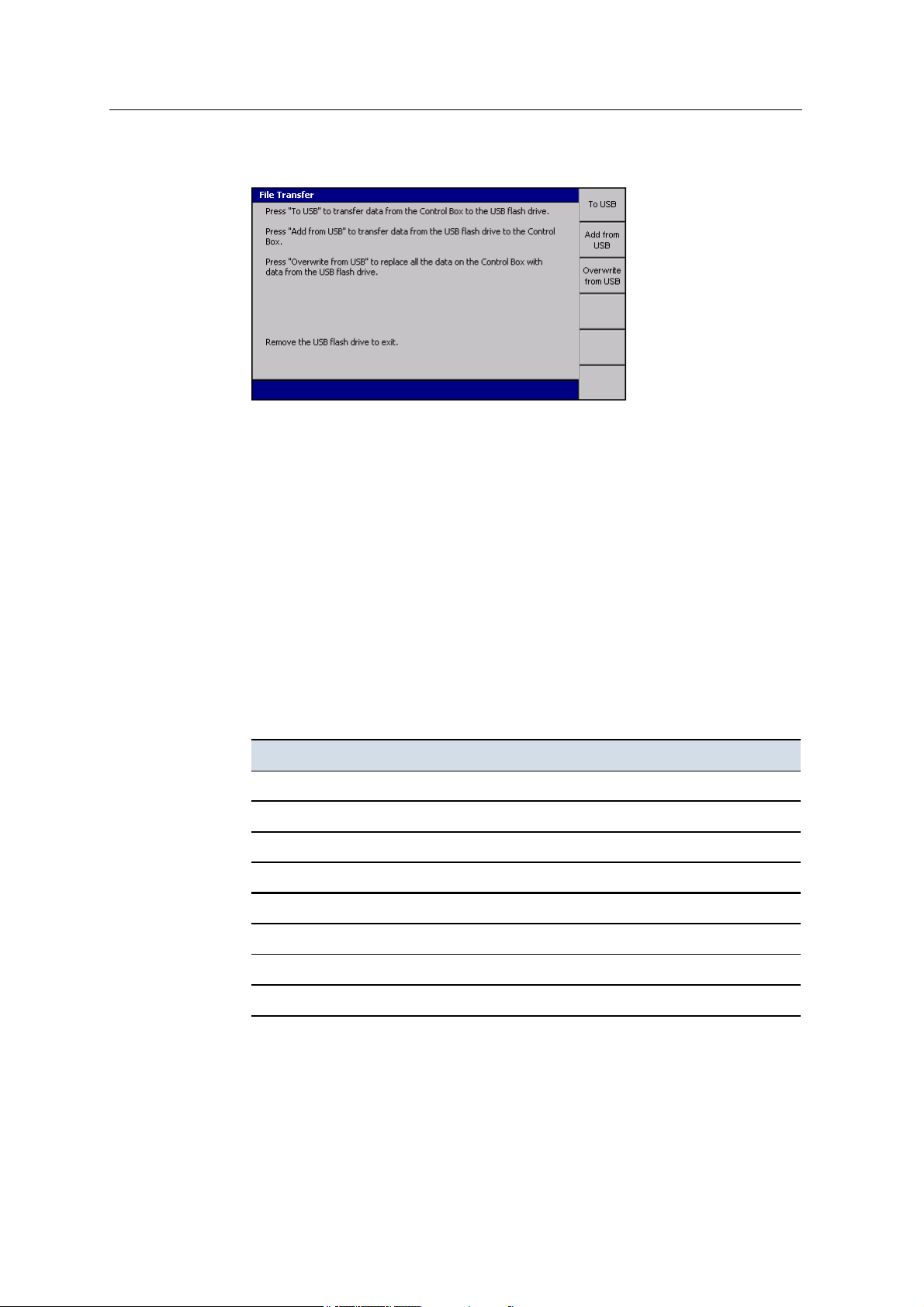
UsingtheControl Box andLightbars 2
dialog appears.
Transferring files to the USB flash drive
Note – If a file or folder to be transferred already has an item with a matching file
name, but different contents on the USB flash drive, the destination item will be
renamed to a backup name generated by appending the item’s last-modified date to
its file name.
1. Press To USB.
Only files that have been generated or modified on the control box transfer to
the “Machine Control Data” folder on the USB flash drive and are written to
the machine’s sub-folder. The machine’s sub-folder name is the same as the
machine name set on the control box.
The following table describes the action that is applied to each file type during
a file transfer to the USB flash drive.
File type Copy Move
Design files
Map design files
Program log files
ZSnap and .gif files
Production .tag files (when 2-way data communication IS NOT enabled)
Production .tag files (when 2-way data communication IS enabled)
Points .csv files
RemoteBase.txt file
P
P
P
P
P
P
P
P
GCS900GradeControlSystem for Excavators Operator's Manual 19
Page 20

2 Usingthe ControlBox andLightbars
Note – A copy action copies the file and leaves the original file on the control
box. A move action copies the file and deletes the original file from the control
box.
A progress bar appears, showing the progress of the data transfer.
2.
To exit, press \ or remove the USB flash drive.
Transferring files from the USB flash drive
Two types of file transfer from the USBflash drive are available:
l Add from USB
l Overwrite from USB
Add from USB
Note – If a file or folder to be transferred already has an item with a matching file
name, but different contents on the display, the destination item will be renamed to a
backup name generated by appending the item’s last-modified date to its file name.
Files and folders matching this backup naming convention, generated by a previous
“to USB” operation, will NOT be transferred from the USB flash drive to the
display.
1. Press Add from USB.
Data in the “\Machine Control Data\MachineName” folder and sub-folders,
and the “\Machine Control Data\All” folder of the USB flash drive transfers to
the control box.
A progress bar appears, showing the progress of the data transfer.
2.
To exit, press \ or remove the USB flash drive.
Overwrite from USB
Note – Use with caution, as this transfer deletes all existing files from the control
box.
1. Press Overwrite from USB. The following actions occur:
a. A warning is displayed. Read the warning message carefully and only
press \ if you are sure you want to continue.
b. The control box is backed up. All current files on the control box are saved
to a backup folder on the USB flash drive. Your site supervisor can restore
from backup.
c. The entire data content is deleted from the control box.
20 GCS900GradeControlSystem for Excavators Operator's Manual
Page 21

UsingtheControl Box andLightbars 2
d. Data in the “\Machine Control Data\MachineName” folder and sub-
folders, and the “\Machine Control Data\All” folder is transferred from
the USB flash drive to the control box.
A progress bar appears, showing the progress of the data transfer.
2.
To exit, press \ or remove the USB flash drive.
Data transfer error messages
When transferring data, a warning message appears when there is insufficient
space on either the control box or the USB flash drive.
Control box storage capacities
Available control box file storage capacities are:
l CB450 - 450 MB
l CB460 - 3.5 GB
Data transfer suspend and resume
If the USB flash drive is removed from the control box, or if the = key is pressed
during a file transfer operation, the file transfer is suspended and will resume when:
l the USB flash drive is re-inserted into the control box, and/or
l the relevant softkey is pressed to resume the last file transfer operation
2.3 Working with control box information
When you work with the control box, you use a mix of keys, softkeys, menus,
dialogs, and guidance screens. The availability of many of these items is determined
by the following factors:
l The sensors installed on the machine. For example, some configuration screens
are only available when particular sensors are installed.
l The guidance configuration of the system. Your selection of guidance method
affects the guidance information available on the display and the guidance
configuration options you get.
l The operator configuration of the system. The menus and screens selected for
you by your site supervisor affect the setup information you can view and
modify.
Note – This manual only covers the menu options that are available to
operators by default.
GCS900GradeControlSystem for Excavators Operator's Manual 21
Page 22
2 Usingthe ControlBox andLightbars
Any configuration and guidance options not covered in this manual are described in
the GCS900 Grade Control System Site Supervisor’s Manual.
2.3.1 Working with menus and dialogs
Before you can begin work, you must enter configuration and set-up information into
the system, and view the current system state, by using screens called menus and
dialogs. Menus let you select a dialog. Dialogs let you specify set-up and
configuration information, or view information about the state of system
components.
Softkeys and softkey labels
Softkeys are the six physical keys immediately to the right of the screen. The
function of these physical keys depends on the information displayed and is
identified by the softkey label beside the key. See Figure 2.3 for an example.
Softkey labels are graphical “keys” that appear down the side of the screen.
The following tables list the softkey labels that display on the guidance screens of
the control box with a brief description of each softkey's functionality.
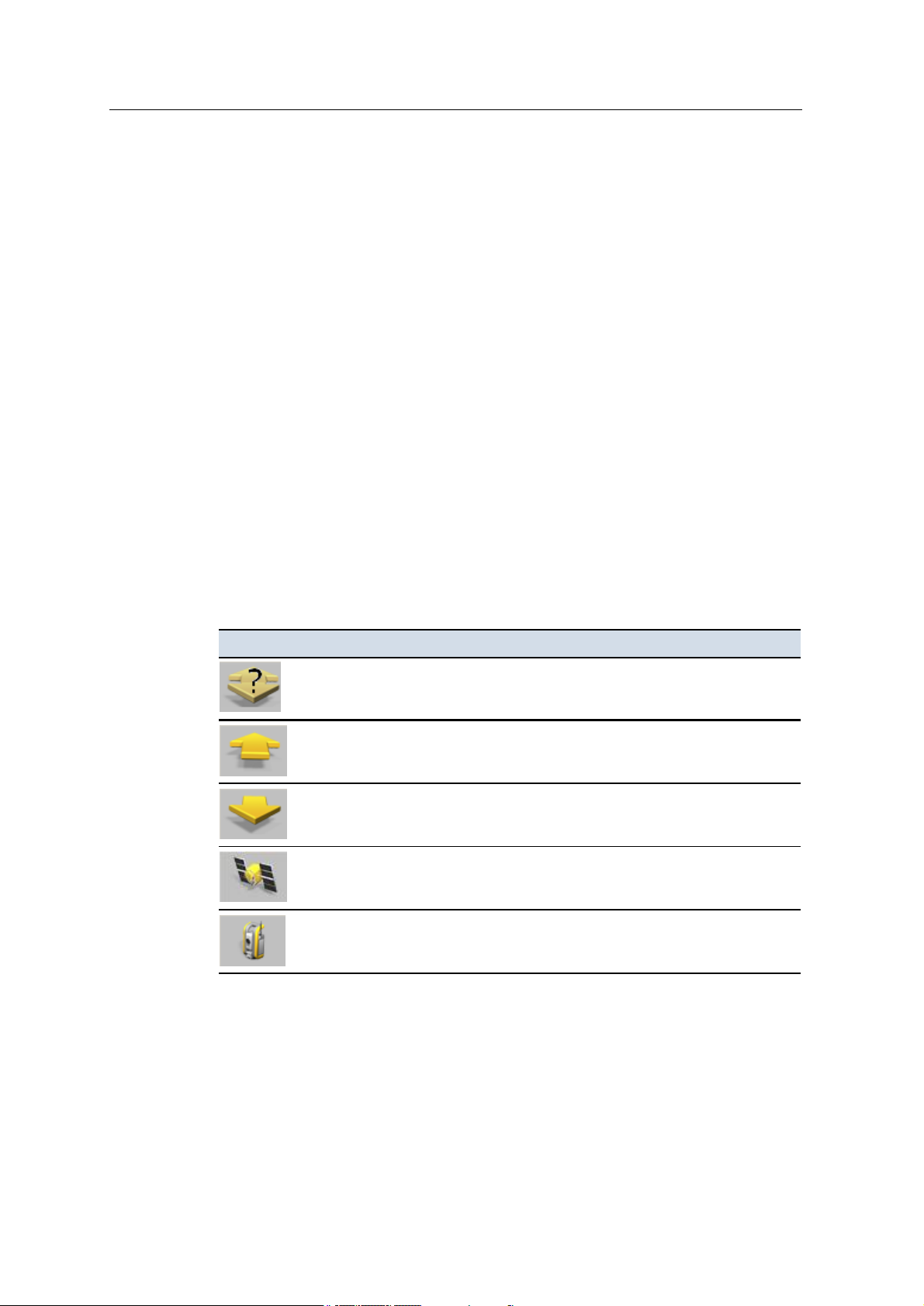
Generic softkey icons
CB4x0 icon Functionality
Direction: Unknown
Direction
Direction: Forward
open the
Direction: Reverse
open the
GPS
UTS
dialog.
Direction
Direction
- Press to open the
- Press to open the
dialog.
dialog.
- Direction of motion is unknown. Press to open the
- Direction of motion is calculated to be forwards. Press to
- Direction of motion is calculated to be in reverse. Press to
dialog.
GPS
dialog.
UTS
22 GCS900GradeControlSystem for Excavators Operator's Manual
Page 23
Excavator softkey icons
CB4x0 icon Functionality
UsingtheControl Box andLightbars 2
Bucket Tip: Center
focus to the right side of the bucket.
Bucket Tip: Left
focus to the center of the bucket.
Bucket Tip: Right
focus to the left side of the bucket.
H. Offset
V. Offset
Map recording softkey icons
CB4x0 icon Functionality
Reset Map
displayed in Manager Mode.
- Focus is on the center of the bucket. Press to change the
- Focus is on the left side of the bucket. Press to change the
- Focus is on the right side of the bucket. Press to change the
- Press to open the
- Press to open the
- Press to open the
Horizontal Offset
Vertical Offset
Reset Map
dialog. (3D only)
dialog. By default, this softkey is only
dialog. (3D only)
Mapping: Auto
working. Press to change map recording to theOnmode.
Mapping: On
data.
Mapping: Off
mode.
Auto
- Map data is recorded when the machine is considered to be
- Map data is recording continuously. Press to stop recording map
- Map data is not recording. Press to change map recording to the
Record Point - Record a point, when point recording is active.
GCS900GradeControlSystem for Excavators Operator's Manual 23
Page 24

2 Usingthe ControlBox andLightbars
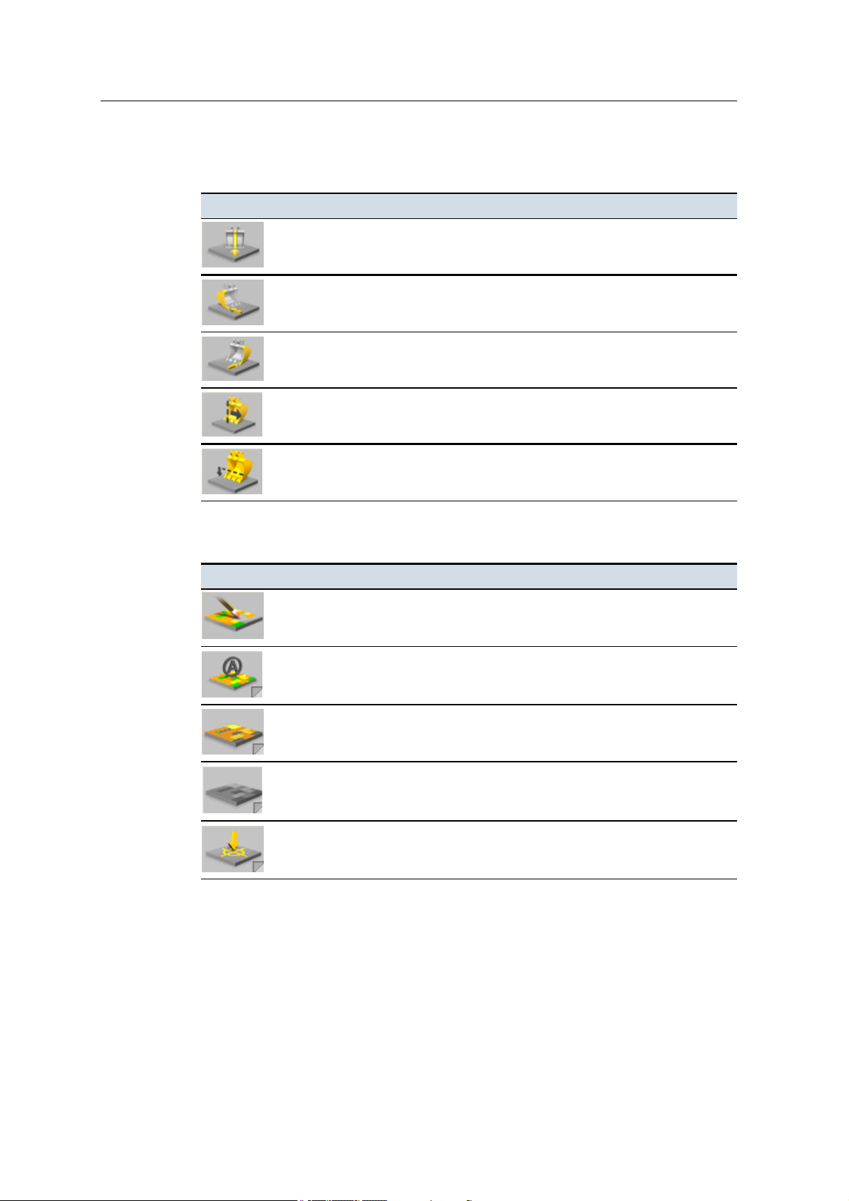
2D Depth and Slope excavator softkey icons
Table 2.1 — Softkey icons
Icon Description
Touch point
Accept laser strike
Depth memory
Slope memory
Depth dual slope memory
Select profile
Flip profile
Select profile origin
Bench
Bench rotation
The text on a softkey label can show the following details:
l A description of the operation that is performed when you press the softkey
once.
l The setting that is currently selected. The text on the softkey label changes
when you press the softkey to switch between options. The top line of the
softkey label ends with a colon (:) and the bottom line shows the current option
or setting.
The icon on a softkey label can show the following details:
24 GCS900GradeControlSystem for Excavators Operator's Manual
Page 25
UsingtheControl Box andLightbars 2
l A graphical representation of the operation that is performed when you press
the softkey once.
l The setting that is currently selected. The icon on the softkey label changes
when you press the softkey to switch between options.
l Softkeys that have a fold on the bottom right corner support press and hold
functionality to directly access the associated operation.
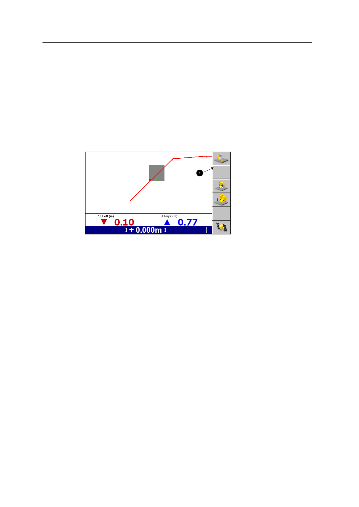
For example, the softkey labels Bucket Tip: Center, Bucket Tip: Left and Bucket Tip:
Right (1) show the side of the bucket that is selected for horizontal guidance on 3D
systems.
Softkey labels
1
Figure 2.3 Example softkey labels on a guidance
screen
Some softkey labels appear in more than one screen, in which case the function of
the softkey they identify is always the same.
As a softkey’s function relates to particular screens or dialogs, that functionality is
only available when the appropriate screen or dialog appears. For example the New
Level function is available only when the Select Design File screen appears, as that
function relates only to that screen.
If a softkey has no function in a screen or dialog, the softkey label is blank.
By convention, this manual refers to a softkey/function combination by softkey
label.
Menus
Menus let you choose another menu or dialog from a list. To move up or down the
list of menu items use the ] or [ keys. Once you highlight the item you want
to view, press \ to select it. See Figure 2.4 for an example.
To leave a menu without making a selection, press =.
GCS900GradeControlSystem for Excavators Operator's Manual 25
Page 26
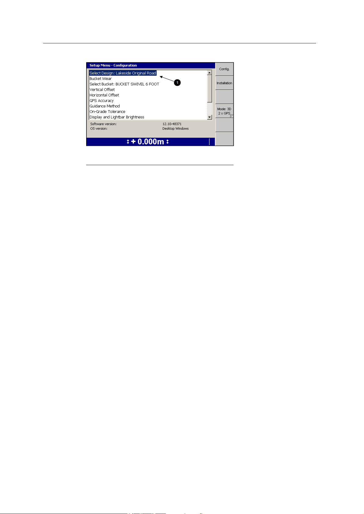
2 Usingthe ControlBox andLightbars
Highlighted menu item
1
Figure 2.4 Example menu
Dialogs
Dialogs let you enter data into the system. Dialogs can contain any of the following
items:
l Text fields. Text fields let you enter text information, such as the name of a
machine. Once you select a field, you can enter data into it. A selected field
appears as white text on a blue background.
l Number fields. Number fields let you enter numerical values, such as the
height of a benchmark. Once you select a field, you can enter data into it. A
selected field appears as white text on a blue background.
l Lists. Lists let you select a single item from a list of items, such as a list of
machine settings files.
l Check lists. Check lists let you select one or more items, or no items, from a
list of items, such as a list of sensors.
l Yes/No fields. Yes/No fields let you enable and disable particular features.
l Information to help you make your selection.
To move between fields in a dialog, press N.
To enter data into a text or number field, use the arrow keys as follows:
l
Press ] or [ to scroll through the upper case alphabet (A through Z),
numbers (0 through 9), the decimal point (.), the negative sign (–), the positive
sign (+), a space ( ), and back to A.
Note – Available values depend on the type of field that is selected. For
example, the only values available for number fields are 0 through 9, the
decimal point (.), –, and +.
26 GCS900GradeControlSystem for Excavators Operator's Manual
Page 27
UsingtheControl Box andLightbars 2
When you change a character in a field, the keys start stepping from the
existing character.
l
) steps to the next character to the right.
In fields that allow spaces, press) twice to insert a space.
l
( steps back one character to the left. This deletes the character in the space
to the left.
To select an item from a list, press ] or [ to highlight the item you want to
select, and press \.
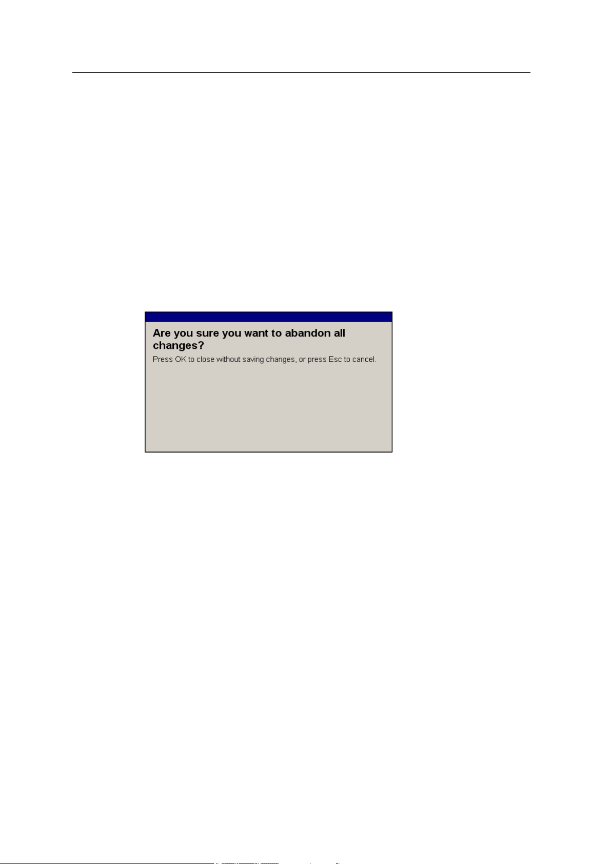
To leave the dialog without saving the new data or selection, press =. If you have
made changes to a dialog setting, and you choose to exit without saving those
changes, the following warning appears:
To confirm that you want to abandon the changes you have made to the dialog, press
\.
2.3.2 Working with guidance screens
While you work, you read guidance information from the system using guidance
screens.
Guidance screens display a mix of text and graphics that give you information such
as the slope or elevation of the cutting edge or the position of the machine.
Depending on the configuration of the system, as setup by your site supervisor, you
can view varying numbers of guidance screens:
l Plan view
l Terrain
l Pass count
l Cut/Fill pass count
l Radio coverage
GCS900GradeControlSystem for Excavators Operator's Manual 27
Page 28
2 Usingthe ControlBox andLightbars
l Cross-section view
l Profile view
l Split screen (profile and cross-section) view
l Level (bubble) view
l Text view 1
l Text view 2
To move between guidance screens, press N.
The availability of each screen, and the information the screen contains, changes
with the following configuration items:
l The sensors installed on the machine
l The guidance configuration of the system
l The operator configuration of the system
l The type of design currently loaded
Guidance screen components
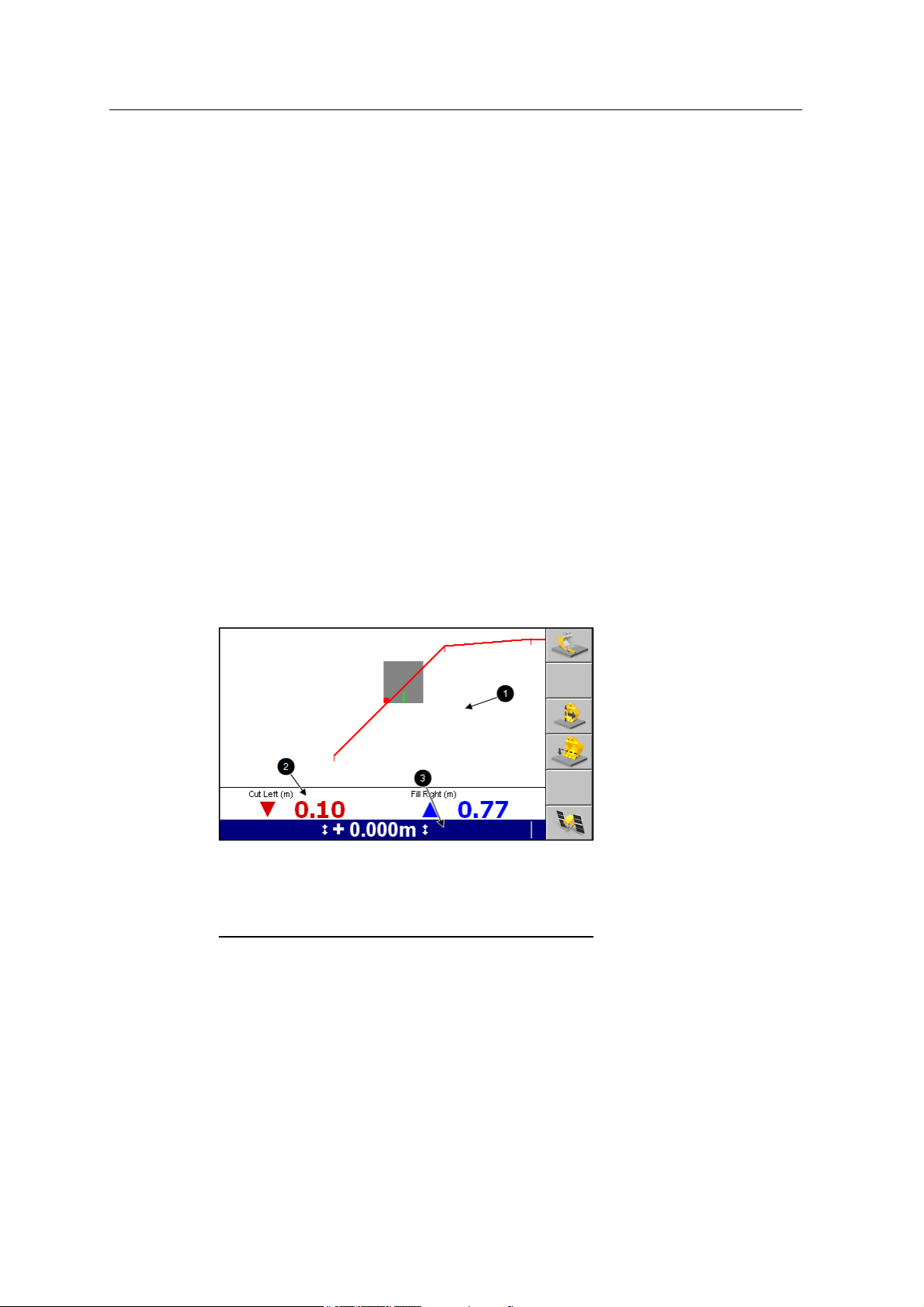
Figure 2.5 shows the main components of the guidance screens:
Guidance view area
1
Guidance settings status
3
bar
Figure 2.5 Guidance screen components
Optional text i nformation
2
area
The three main areas of a guidance screen are:
l The guidance view area. The guidance view area displays the machine
relative to the surface being worked. There is no guidance view area in the text
screens.
28 GCS900GradeControlSystem for Excavators Operator's Manual
Page 29
UsingtheControl Box andLightbars 2
l The optional text information area. The text information area lets you view
user-selectable information. In the text screen guidance views, the text
information area uses the guidance view area.
If there are more than three text items selected for display, then the text
information area appears down the right side of the screen.
If there is no text information configured for that view, the text information
area does not appear.
l The guidance settings status bar. The guidance settings status bar displays
the current sensors and guidance settings being used to generate guidance
information. For more information, see Guidance settings, page 30.
Machine icons
The system uses a variety of icons to identify the machine in the guidance views:
l The bucket icon provides information on the bucket slope in cross-section view.
l The cutting edge tip in an icon corresponds exactly to the cutting edge tip of the
machine.
l The bucket edge in an icon corresponds exactly to the bucket cutting edge of
the machine.
l As you move the machine and bucket, the icon mimics the movements on the
screen.
l The red square on the bucket indicates the horizontal guidance point (the
bucket focus), if applicable. The green line on the bucket indicates the vertical
guidance point(s).
Note – The position of symbols for other parts, in particular the tracks/wheels or
rear corners, are approximate and for indication only.
Table 2.2 — 3D guidance machine type and icon
Machine type Plan View icon Profile View Icon
Excavator
GCS900GradeControlSystem for Excavators Operator's Manual 29
Page 30
2 Usingthe ControlBox andLightbars
Machine type Plan View icon Profile View Icon
Excavator with variable angle boom
Table 2.3 — 2D Depth and Slope guidance machine type and icon
Machine type Profile View Icon
Excavator
Excavator with variable angle boom
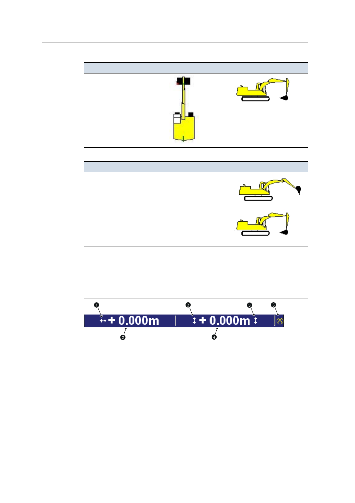
Guidance settings
To display guidance settings, the system uses a variety of icons to identify the
sensors being used to generate guidance information, and text to display numerical
values.
3D horizontal guidance
1
icon
Vertical offset
4
Figure 2.6 Example guidance setting area for a 3D excavator system
Horizontal offset
2
Mapping/Recording icon -
5
set to Auto
Elevation guidance icons
3
30 GCS900GradeControlSystem for Excavators Operator's Manual
Page 31

UsingtheControl Box andLightbars 2
Slope memory icon
1
Elevation offset
4
Figure 2.7 Example guidance setting area for a 2D Depth and Slope excavator
system
Table 2.4 — Guidance setting icons used by the system
Guidance setting icon Meaning
Elevation guidance is available.
For Depth and Slope systems, the system has been benched, but the
benchmark elevation has not been referenced to a laser plane.
3D horizontal guidance information is being generated.
Use of a laser catcher is enabled i n the installation menu.
Elevation guidance is available. The system has been benched and
the benchmark elevation has been referenced to a laser plane.
The system has no bench. The bench data has been cleared. The
Bench Required
Elevation guidance is available. The system is using a laser plane
as the elevation reference.
Current slope memory
2
Laser catcher enabled
4
3D vertical guidance information is being generated.
flashing message is displayed.
2D elevation guidance
3
icon
Auto
On
Off
Slope guidance is available.
Note – The icon illustrated indicates positive slope.
Reliable bucket tilt data i s temporarily unavailable, typically due to
radial movement of the arm or curling of the bucket.
No avoidance zone guidance is available. (3D only)
Mapping/Recording status.
GCS900GradeControlSystem for Excavators Operator's Manual 31
Page 32

2 Usingthe ControlBox andLightbars
Zooming the view
There are four possible ways of zooming a view:
l
Press + to zoom in on the current view.
l
Press - to zoom out of the current view.
l
Press and hold + to zoom the machine.
l
Press and hold - to zoom out as much as possible.
Tip – The system saves the sizes of the views when you turn off the control box. The views
automatically load at their previous size when you next use the system.
2.3.3 Guidance views
Guidance views enable the operator to view the machine guidance in a variety of
ways.
Split screen view
The split screen view displays both the profile view and cross-section view in a
single screen. Split screen view is useful for monitoring the position of the bucket
cutting edge, relative to the guidance surface.
Note – The split screen view replaces both the cross-section and profile views;
when the split screen view is available, you cannot view the cross-section and
profile views as full screen views.
Level (bubble) view
Level view displays the current pitch and roll of an excavator, and is useful for
helping you to level the machine.
Level view displays a level bubble, horizontal and vertical level bars, and an angle
measurement. The level bubble provides a visual representation of the current pitch
32 GCS900GradeControlSystem for Excavators Operator's Manual
Page 33

UsingtheControl Box andLightbars 2
and roll information coming from the pitch and roll sensor(s). The Pitch and Roll
text items appear in level view by default, and are the only text items available.
The outer ring represents 45°; the inner ring represents 22.5°.
The bubble, the horizontal and vertical level bars, and the text items all update as
the machine moves and the pitch and roll readings change.
Figure 2.8 shows the level view for the Depth and Slope excavator system.
Inner ring
1
Outer ring
3
Machine roll
5
Figure 2.8 An example of a level view
Level bubble
2
Machine pitch
4
The level bubble units are the same as the cross slope units set in the Units dialog.
When the pitch and/or roll sensor(s) are not connected, or when a value is not
available, N/A appears for that value and the bubble does not appear.
Text view 1 and text view 2
The site supervisor configures the text items that display in text view 1 and text
view2. The following figure shows an example text view guidance screen.
GCS900GradeControlSystem for Excavators Operator's Manual 33
Page 34

2 Usingthe ControlBox andLightbars
Note – Up to 10 text view items can be displayed in full screen view and the text
size scales automatically to fit the available screen space.
2.4 Understanding lightbar information
The system uses LED arrays, called lightbars, to provide the operator with guidance
information.
Lightbars let you simultaneously view guidance information, the cutting edge, and
the surface being worked.
The CB460 control box supports either internal or external lightbars. The
characteristics of internal and external lightbars differ as follows.
2.4.1 External lightbars
External lightbars can be installed in the cab, as required to replace the internal
lightbars.
Note – External lightbars are only supported on CB430 and CB460 control boxes.
In each external lightbar there are seven sets of LEDs in two colors, as shown
below.
Amber LEDs
1
Figure 2.9 LB400 external lightbar LEDs
Green LEDs
2
When the cutting edge is within half of the on-grade or on-line tolerance, only the
central green LED is lit. When the cutting edge is within the on-grade or on-line
tolerance, the central green LED and one other green LED are lit. If any LED,
other than a green LED is lit, then the cutting edge is off grade or off line.
When the drum is within half of the on-grade or on-line tolerance, only the central
green LED is lit. When the drum is within the on-grade or on-line tolerance, the
central green LED and one other green LED are lit. If any LED, other than a green
LED is lit, then the drum is off grade or off line.
34 GCS900GradeControlSystem for Excavators Operator's Manual
Page 35

2.4.2 Internal lightbars
Internal lightbars are built into the control box and can be disabled if not required.
In each internal lightbar there are seven LEDs in two colors, as shown below.
UsingtheControl Box andLightbars 2
Amber LEDs
1
Figure 2.10 Control box internal lightbar LEDs
When the cutting edge is within the on-grade or on-line tolerance, only the central
green LED is lit. If any LED, other than a green LED is lit, then the cutting edge is
off grade or off line.
Excavator lightbar behavior depends on the system installed. The following sections
describe how Depth and Slope and 3D guidance information is displayed using
lightbars.
2.4.3 3D excavator lightbar behaviour
Up to three lightbars can be used with a 3D excavator system. Each lightbar shows
different information about the bucket position:
l The left vertical cut/fill lightbar provides corrections for cut and for fill. This
lightbar displays information for the lowest bucket tip relative to the design.
l The horizontal left/right lightbar indicates left and right corrections to the arm
position relative to the horizontal alignment, for the bucket tip that has focus.
l The right vertical reach lightbar indicates extension and retraction corrections
to the arm position relative to the horizontal alignment line, for the bucket tip
that has focus.
2
Green LED
Only one of either the horizontal lightbar or the right vertical lightbar is active at
any one time. The system automatically selects which lightbar is activated, based
on the excavator’s orientation relative to the selected horizontal alignment.
The left vertical cut/fill lightbar gives guidance to only one bucket tip at a time and
indicates guidance to the following points:
l The bucket tip with the smallest Cut value, when both bucket tips are above the
temporary working surface.
GCS900GradeControlSystem for Excavators Operator's Manual 35
Page 36

2 Usingthe ControlBox andLightbars
l The bucket tip with the largest Fill value, when both bucket tips are below the
temporary working surface.
l The Fill bucket tip, when one bucket tip is below and one bucket tip is above
the temporary working surface.
Note – For machines fitted with a tilting bucket, the lightbar gives guidance to one
bucket tip at a time in the same way as described above.
Tip – Use text items to see the cut/fill values for both bucket tips at the same time.
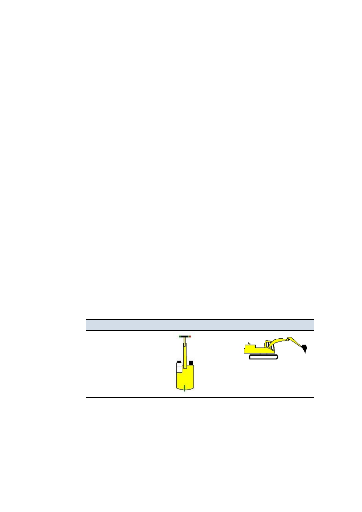
Left vertical cut/fill lightbar guidance
The cut/fill lightbar on an excavator gives on-grade guidance to the working
surface, as shown in Figure 2.11.
Cut/fill lightbar
1
Figure 2.11 Excavator vertical cut / fill 3D guidance
Horizontal left/right lightbar guidance
Excavators can operate parallel to a horizontal alignment. Horizontal guidance is
given by the left/right lightbar once the excavator has turned so that it is parallel to
the selected alignment. See Figure 2.12
36 GCS900GradeControlSystem for Excavators Operator's Manual
Lowest tip guidance. One amber LED lit. Cut
2
down.
Page 37

UsingtheControl Box andLightbars 2
Left/right lightbar
1
Figure 2.12 Excavator horizontal left/right 3D guidance
Left/right guidance. One amber LED lit. Steer
2
left.
Right vertical extend/retract lightbar guidance
An excavator can also work square to (toward) an alignment. The right vertical
extend/retract lightbar guidance gives extension guidance to the selected alignment.
This is shown in Figure 2.13.
GCS900GradeControlSystem for Excavators Operator's Manual 37
Page 38

2 Usingthe ControlBox andLightbars
Extend/retract lightbar
1
Figure 2.13 Excavator reach 3D guidance
2.4.4 2D excavator lightbar behavior
Note – The horizontal lightbar is not currently used in 2D excavator systems.
Extension guidance. Three amber LEDs lit and
2
flashing. Retract arm to move bucket in.
Bucket guidance. Green and three amber
1
LED lit. Lower bucket.
Figure 2.14 Using a 2D excavator’s lightbars
38 GCS900GradeControlSystem for Excavators Operator's Manual
Laser strike guidance. No LEDs lit. No
2
laser strike.
Page 39

The left lightbar displays cut/fill information. The cut/fill information is relative to
the guidance surface under the bucket.
The right lightbar behaves in the following way when the laser catcher receives
laser strikes:
l Green LED lit – laser strike detected in the center of the laser catcher window.
l Green and two amber LEDs lit – laser strike detected close to the center of the
laser catcher window.
l Green and three amber LEDs lit – laser strike detected far from the center of
the laser catcher window.
l No LEDs lit. No laser strike detected.
To set lightbar brightness, see 3.4.6 Lightbar brightness.
2.5 3D remote switch
The 3D excavator system supports the use of a remote switch for:
UsingtheControl Box andLightbars 2
l turning map recording events on and off:
Pass count coverage – On/Off/Auto.
Radio Map – On/Off/Auto.
Terrain – On/Off/Auto.
Cut/Fill Map – On/Off/Auto.
l recording a point.
Configuration of which of these events (if any) is available is managed by your Site
Supervisor.
Note – 3D remote switch support is not available when using a 2D Depth and Slope
system.
2.6 System beeper
In addition to the display and lightbars, the system also uses an audible alarm, or
beeper, to alert you to status changes and other events.
The following table lists the pattern of sounds generated by the beeper, and the
events that cause them. By default, the beeper will sound for all the events listed in
the table, but alerts for some events may be turned off by your site supervisor.
GCS900GradeControlSystem for Excavators Operator's Manual 39
Page 40

2 Usingthe ControlBox andLightbars
Table 2.5 — Beeper patterns
Event Sounds when... Pattern
Inside Avoidance Zone the machine is inside an avoidance zone. Repeated:
150 msec on,
175 msec off,
300 msec on,
175 msec off
Above Grade the bucket is more than the vertical tolerance and less
than four times the vertical tolerance above grade.
On-Grade the bucket is within the vertical tolerance of grade. Continuous:
Below Grade the bucket is more than the vertical tolerance and less
than four times the vertical tolerance below grade.
Approach Avoidance Zone the machine is within the warning distance of an
avoidance zone.
No Avoid the No Avoid message appears. Once only:
Warning Message Appears a warning message appears. Once only:
Warning Message Disappears a warning message automatically disappears. Once only:
GPS Accuracy the GPS accuracy level changes. Once only:
Continuous:
50 msec on,
50 msec off
On
Continuous:
100 msec on,
100 msec off
Once only:
200 msec on,
200 msec off,
400 msec on
200 msec on
200 msec on,
200 msec off,
200 msec on
200 msec on
200 msec on
UTS Tracking the UTS loses lock on the machine target. Once only:
200 msec on
Laser Alerts a l aser strike is detected in the laser catcher window. Once only:
200 msec on
Key/Switch Beeps a key or a switch is pressed. Once only:
200 msec on
40 GCS900GradeControlSystem for Excavators Operator's Manual
Page 41

C H A P T E R
3
3Preparing to Work
In this chapter:
n Power up checks
n Software option keys
n Work preparation checks
n Configuring the machine radio
n Wi-Fi networking
n Exchanging files with a
Connected Community filespace
n Selecting an excavator bucket
n Selecting a 3D vertical guidance
method
n Selecting a Depth and Slope
vertical guidance method
Before you begin work with the GCS900 Grade
Control System, you need to check the state of
the machine and its system components to
ensure the system provides accurate guidance.
GCS900GradeControlSystem for Excavators Operator's Manual 41
Page 42

3 Preparingto Work
3.1 Introduction
This chapter describes how to check the machine before you turn on the system,
what to look for as the system powers up, and how to check the general system
setup once the system is running.
3.2 Power up checks
ATTENTION — In cold environments, when you start the machine to warm it up turn on the
control box as well.
When you power up the system to begin work, observe the system’s start-up
sequence to make sure that all components function correctly. See the following list
of basic checks.
Check For more information, see ...
Lightbar power up
Control box power up
3.2.1 Lightbar power up
Observe the lightbars during start-up and make sure that the lightbars work
correctly.
To perform the lightbar start-up check:
1.
To turn on the system power, press P on the control box.
2. Immediately observe the pattern of the lightbar LEDs.
The LEDs flash in the following sequence:
LEDs on this lightbar Flash
Cut / fil l Bottom to top
Left / right Left to right
In / out (extend / retract) Top to bottom
All Twice, simultaneously
3.2.1 Lightbar power up
3.2.2 Control box power up
The following problems may occur with internal lightbars:
Problem Action
Lightbars do not
illuminate
42 GCS900GradeControlSystem for Excavators Operator's Manual
Use the methods described in 3.2.2 Control box power up to check that
the control box has started successfully.
Page 43

Preparingto Work 3
Problem Action
Use the procedure descri bed in 3.4.6 Lightbar brightness to check that
the lightbar brightness is not set too low.
The following problems may occur when you power up the external lightbars:
Problem Action
Lightbars do not
illuminate
Lightbars flash in the
wrong sequence
3.2.2 Control box power up
Observe the control box after the system has powered up.
You should see a guidance screen, softkeys, and optional text items (if configured).
If the machine has one or more 3D sensors installed and configured, the following
items appear:
l A plan view guidance screen.
l The correct machine icon for your machine type.
l A site plan, if the system has a site plan file.
l A design or map, if one was loaded when the system was last powered down.
Use the methods described in 3.2.2 Control box power up to check that
the control box has started successfully.
Use the procedure descri bed in 3.4.6 Lightbar brightness to check that
the lightbar brightness is not set too low.
Check the system harness between the control box and the lightbars.
The lightbars have probably been install ed incorrectly. Consult your site
supervisor.
The following problems may occur when you power up the control box and the
system:
Problem Action
Control box does not start Check that the master disconnect switch and machine power switch
are on.
Check the ignition switched power cable section of the system
harness.
Start-up is interrupted by the “Error loading
avoidance zone” error message
Start-up completes but the error message
“Some of the required devices are not
responding” appears
Start-up completes but the error message The system has detected a discrepancy between a configured
The avoidance zone file is corrupt. Consult your site supervisor.
A device specified during system configuration is missing or not
connected. Follow the procedure described in
diagnostics
.
7.3 Running system
GCS900GradeControlSystem for Excavators Operator's Manual 43
Page 44

3 Preparingto Work
Problem Action
“Check Machine Dimensions” appears machine dimension, and an observed one, possibly because an
incorrect machine configuration file has been loaded. Consult your site
supervisor.
Start-up completes but the wrong machine
icon appears on the guidance screen
3.3 Software option keys
The system supports an enhanced option key model based on specific machine types
and functionality. For more information contact your dealer.
3.3.1 Option key structure
The machine/functionality option keys control which machines have which levels of
functionality. The functionality levels are hierarchical in ascending capability:
l 3D Automatics
l 3D Indicate
l 2D Automatics
Each higher level contains all levels of functionality below it.
3.3.2 Software support
An incorrect machine configuration file has been loaded. Consult your
site supervisor.
For new CB450 and CB460 control boxes the software will self-generate the initial
12 months of software support. If no software support date is set then an initial
dialog screen will be presented to the operator. The operator can either press
softkey 3 to activate 12 months of software support or decide not to do this at that
time.
If software support is not activated, the software will function normally for 60
minutes after which time it will cease to calculate machine positions, making the
software unusable for machine control. On the next power cycle, if software
support is still not set then the same initial screen is presented to the user.
To extend this software support date, 12-month software support extension option
keys are available via the Trimble Store.
3.3.3 Troubleshooting option keys
In the absence of a valid option key for at least one machine type, the system
displays a persistent Option not Installed flashing message and does not resolve any
machine position information.
44 GCS900GradeControlSystem for Excavators Operator's Manual
Page 45

When a machine settings file is restored that specifies a machine type not supported
by the current option key set, the following full screen error message is displayed:
The system lacks the Option Keys necessary to support the configured machine type.
When a machine settings file specifies a supported machine type but includes
settings relating to a level of functionality not currently supported, the settings will
be loaded but will not be enabled. After the load has completed, the following full
screen warning message is displayed:
Not all the settings in the selected machine settings file could be loaded, the system
lacks the Option Keys necessary to fully support the specified machine configuration.
After the correct option key is loaded the settings, as described by the loaded
machine settings file, should be usable.
3.4 Work preparation checks
As you get ready to begin work, you need to prepare the system for the job. Perform
the following work preparation tasks as and when described below.
Preparingto Work 3
Check and set ... When To learn how, see ...
Machine settings As instructed by your site supervisor, or if an error in
machine dimensions is reported
l
Mode selection
Main screen views As required for the current job and environment
Display brightness Every power-up
Keypad backlight
brightness
Lightbar brightness Every power-up
Display settings As instructed by your site supervisor
Lightbar tolerances As instructed by your site supervisor, or when there is a
Bucket wear As instructed by your site supervisor
When you restore machine settings
l
When devices have been added or removed
l
When you need to switch between guidance systems
Every power-up
significant change in material or accuracy requirements
3.4.1 Machine settings
3.4.2 Switching guidance
modes
3.4.3 Main screen views
3.4.4 Display brightness
3.4.5 Keypad backlight
brightness
3.4.6 Lightbar brightness
3.4.7 Display settings
3.4.8 Lightbar tolerances
3.4.10 Checking bucket
wear
Note – When excavating underwater, do not submerge the sensors deeper than
20meters (66feet).
Note – Underwater excavation is only supported when using a dedicated
underwater solution.
GCS900GradeControlSystem for Excavators Operator's Manual 45
Page 46

3 Preparingto Work
3.4.1 Machine settings
To ensure accurate guidance, you must use the correct machine settings. Machine
settings are typically saved in a machine settings file.
To view your current machine settings:
1.
Press M from any guidance screen.
2. Press Installation.
3. Select Machine Settings.
4.
Press = to exit.
Saved settings include calibration settings for AS300/AS45x sensors.
All saved machine settings are restored, with the following exceptions:
l Calibration settings for AS21 sensors are not saved in a machine settings file,
and are not restored when you restore the settings file.
l To learn more about sensor calibration, refer to the Site Supervisor's manual.
To view your current machine settings, select Machine Settings from the Setup
Menu - Installation menu.
To restore a machine settings file:
1.
From any guidance screen, press M.
2. Select Restore Settings. The Restore Settings dialog appears.
3. Select Machine Settings.
4. Select the correct setting file for your machine.
5.
To confirm the settings, press \; to exit without saving the changes, press
=.
Changes take effect immediately.
46 GCS900GradeControlSystem for Excavators Operator's Manual
Page 47

The following problems may occur when you try to restore machine settings:
Problem Action
Invalid machine settings file The machine settings file is corrupt.
No settings suitable for your machine The machine settings data is incorrect.
3.4.2 Switching guidance modes
You can use a variety of guidance modes even if the sensors required for a
particular configuration are not detected.
Use the Mode softkey to switch between systems, as an alternative to using multiple
machine settings files:
1.
From any guidance screen, press M. The Mode:<value> softkey indicates the
current guidance mode.
Preparingto Work 3
The machine settings are for the wrong machine type.
Consult your site supervisor.
Consult your site supervisor.
2. If required, press Mode: <value> to switch to a different mode. When a new
sensor or device is added to or removed from the machine, the system
automatically updates the mode values.
Note – To choose from a list of available systems or to enable / disable specific
systems, press and hold Mode: <value>.
3.4.3 Main screen views
The system features a new Configuration Menu item called Main Screen Views.
Main Screen Views allows the user to configure some views on the main screen to
suit the specifics of the current job and environment.
GCS900GradeControlSystem for Excavators Operator's Manual 47
Page 48

3 Preparingto Work
The following tables describe the functions that can be adjusted using Main Screen
Views.
Note – Some of the items listed in the following table may not apply to your system.
Table 3.1 — Main screen views - Plan views
Item Options Description
Rotation Yes / No Yes - Keeps the machine facing up the display.
No - The plan view is drawn north-up.
Auto pan Yes / No Yes - Pans the display to keep the machine
displayed.
No - The plan view will not pan if the machine
drives off the display.
l
Display recorded
points
Points only
l
Points and Names
l
None
Table 3.2 — Main screen views - Active views
Item Options Description
l
Only displays the points
l
Displays the points and point names
l
Does not display points
Plan (no mapping) Yes / No Yes - A plan view with no mapping content is avail able.
Terrain Yes / No Yes - A plan view with terrain mapping is available.
Cut/Fill Yes / No Yes - A plan view with cut/fill mapping is available.
Pass count Yes / No Yes - A plan view with pass count is available.
Radio coverage Yes / No Yes - A plan view with radio coverage mapping is
available.
Profile Yes / No Yes - A profile view is available.
Cross section Yes / No Yes - A cross section view is available.
Text view 1 Yes / No Yes - A text vi ew is available.
Text view 2 Yes / No Yes - A second text view is available.
Split view Yes / No Yes - A profile and cross section split view is available.
Level view Yes / No Yes - A level bubble view is available.
Table 3.3 — Main screen views - Main Screen Softkeys
Item Options Description
l
Mapping Softkey
None
l
Mapping: On/Off/Auto
l
Reset Maps
l
Record Point
Configure the function of the main screen
view mapping softkey.
l
Mapping Softkey 2
None
48 GCS900GradeControlSystem for Excavators Operator's Manual
Configure the function of the main screen
view mapping 2 softkey.
Note – Compactor systems only.
Page 49

Item Options Description
Press and Hold
3.4.4 Display brightness
Use the following key combinations to adjust the brightness of the control box
display for your working conditions:
l
To increase the display brightness, hold down M and press +.
l
To increase the display brightness, hold down M and press -.
l
Mapping: On/Off/Auto
l
Reset Maps
l
Record Point
l
In-Field Report
l
None
l
Record Point
Preparingto Work 3
When Record Point is selected, press and
hold
Record Point
Mapping/Recording
Record Point dialog.
or
to display the
Note – You can also set the display brightness using the Display and Lightbar
Brightness dialog from the Setup Menu – Configuration menu.
3.4.5 Keypad backlight brightness
The control box keypad backlight brightness can be adjusted by the operator to suit
operating conditions.
To check and adjust the keypad backlight brightness:
1.
From any guidance screen, press M.
2. Select Display and Lightbar Brightness.
3. Press Keypad.
GCS900GradeControlSystem for Excavators Operator's Manual 49
Page 50

3 Preparingto Work
4. Use one of the following tools to set the lightbar brightness:
Use the arrow keys to increase or decrease the value of the Keypad
Backlight Brightness field.
Press Set Maximum to set the value to the maximum of 15.
5.
To confirm the settings, press \; to exit without saving the changes, press
=.
3.4.6 Lightbar brightness
To check and adjust the lightbar brightness for your working conditions:
1.
From any guidance screen, press M.
2. Select Display and Lightbar Brightness. The control box screen of the Display
and Lightbar Brightness dialog appears.
3. Press Lightbar.
4. Use one of the following tools to set the lightbar brightness:
Use the arrow keys to increase or decrease the value of the Lightbar
brightness field.
Press Set Maximum to set the value to the maximum of 15.
5.
To confirm the settings, press \; to exit without saving the changes, press
=.
3.4.7 Display settings
Note – You do not need to restore machine and/or display settings files every time
you start the control box, as the system automatically saves and reloads the settings
that were being used before the last shut down.
Use the display configuration that has been created for you. To restore a display
settings file:
50 GCS900GradeControlSystem for Excavators Operator's Manual
Page 51

Preparingto Work 3
1.
From any guidance screen, press M.
2. Select Restore Settings. The Restore Settings dialog appears.
3. Select Display Settings.
4. Select the correct setting file for your use.
5.
To confirm the settings, press \; to exit without saving the changes, press
=.
3.4.8 Lightbar tolerances
Note – In systems that do not have lightbars configured, you should still check the
on-grade tolerances for the Cut/Fill text items using the On-Grade Tolerance dialog
in the Setup Menu – Configuration menu. The interface is similar to the interface
described in this section.
The lightbar tolerances control not only the way the lightbar LEDs are lit, but also
how far the cutting edge can be from design before the Off Grade message is
displayed.
To check and/or set the tolerance thresholds (scales) for the lightbars:
1.
From any guidance screen, press M.
2. Select Lightbar Scales.
GCS900GradeControlSystem for Excavators Operator's Manual 51
Page 52

3 Preparingto Work
Figure 3.1 External lightbar scale dialog
Figure 3.2 Internal lightbar scale dialog
3. Press either Vertical or Horizontal to view the current vertical or horizontal
tolerance settings respectively.
Note – The tolerances for both horizontal lightbars are set to the same value.
When a Depth and Slope guidance method is selected, only the left (cut/fill)
lightbar is affected by the settings in the Lightbar Scales dialog.
4. If required, use the following tools to set the off grade distance at which the
green LED(s) are lit. The value must be between 0m and 12.5m (41ft):
Edit the Vertical Tolerance or Horizontal Tolerance field directly.
Press Default Set <value> to set the tolerance to the default value.
Press Half Set <value> to set the tolerance to half of the current value.
Press Double Set <value> to set the tolerance to twice the current value.
Note – The remaining threshold values are calculated automatically, and
appear in the dialog. The values shown on these softkeys will change,
depending on the current tolerance value.
5.
To confirm the settings, press\; to exit without saving the changes, press
=.
52 GCS900GradeControlSystem for Excavators Operator's Manual
Page 53

Any changes take effect immediately.
3.4.9 Set depth and slope increment values
Depth and Slope excavator systems provide an interface that enables you to set the
amount by which depth and slope values are incremented and decremented. These
values appear on the increment and decrement softkeys in the Depth Memories and
Slope Memories dialogs.
Note – The Depth Memories and Slope Memories dialogs are described in 4.3
Selecting or creating a guidance model.
To set increment/decrement values:
1.
From any guidance screen, press M.
2. Select Increment Adjustment.
Preparingto Work 3
3. To set the vertical offset increment and/or the slope increment:
Edit the Vertical offset increment: or Slope increment: fields directly.
Press Default <value> to set the increment/decrement amount to its default
value.
4.
To confirm the settings, press \; to exit without saving the changes, press
=
3.4.10 Checking bucket wear
You must regularly check the changes in the cutting edge measurements caused by
bucket wear, or as instructed by your site supervisor. To check and/or set the bucket
wear compensation:
1. Measure the cutting edge height to the bucket wear control point. The bucket
wear control point was defined when the bucket was first measured up.
GCS900GradeControlSystem for Excavators Operator's Manual 53
Page 54

3 Preparingto Work
If the bucket wears unevenly, use an average value. However, guidance will
never be better than the range of the differences in cutting edge height.
2.
From any guidance screen, press M.
3. Select Bucket Wear.
4. If required, edit the Length J-J1 field.
Note – If the bucket teeth are longer now than when the bucket was first
measured up, enter a negative value.
5.
To confirm the settings, press \; to exit without saving changes, press =.
The changes take effect immediately.
3.5 Configuring the machine radio
The machine radio communicates with the GPS base station radio.
The machine radio communicates with the UTS instrument radio.
The Machine Radio Configuration dialog is available when your system uses one of
the following radio modems:
Use this radio ... With ...
SNR2400 A UTS system.
SNR2410 or SNR2420 A UTS or GPS system.
SNR900 or SNR910 A GPS system.
SNR450 or SNRx10 A GPS system.
To open the Machine Radio Configuration dialog:
1.
From any guidance screen, press M. The Setup Menu–Configuration dialog
appears.
2. Press Installation. The Setup Menu–Installation dialog appears.
54 GCS900GradeControlSystem for Excavators Operator's Manual
Page 55

Preparingto Work 3
3. Select Machine Radio Configuration. The Machine Radio Configuration dialog
appears, and the system searches for a radio.
Note – For the SNR450 radio-modem it may take some time before a
connection is made.
4. Use the arrow keys to enter information into the Machine Radio Configuration
dialog. To save the changes, press \; to exit without saving changes,
press=.
The Machine Radio Configuration dialog displays different fields, depending on your
radio type. Two examples are shown below:
l For a 900MHz radio on a GPS system:
Note – This release of the system requires the use of SiteVision Office 7.4 or
later for wireless communications over 900 MHz radios. For more
information, refer to the site supervisor's manual.
l For a 2400MHz radio on a UTS system:
The Radio Status field can provide the following messages:
GCS900GradeControlSystem for Excavators Operator's Manual 55
Page 56

3 Preparingto Work
This message ... Displays when the ...
To configure
this radio ...
Not Found
Configuring
Configuration failed
Connected
App <version num.>
System cannot communicate with the radio.
Radio is currently being configured.
Radio configuration failed.
Radio connects to the system.
Radio firmware must be upgraded to the specified versi on.
required
Loader <version num.>
Radio firmware must be upgraded to the specified versi on.
required
System Error
This radio type cannot be
Firmware is not installed correctly.
System connects to an unsupported radio.
configured.
UTS incompatible
GPS incompatible
System connects to a 900MHz radio for use with an SPSx30 UTS.
System connects to an SNR2400 radio for use with a GPS system.
The Machine Radio Configuration dialog enables you to set either the network or
channel that both the system and UTS or GPS communicate over. The following
table outlines how to configure your machine radio:
Confirm that you have
turned on the ...
Enter this into the
Configuration
dialog ...
Machine Radio
Also configure the same ...
SNR900 SNR900 machine radio A network number between 1-40 Network number on the radio-
modem (through the base station
radio display)
SNR910 SNR910 machine radio A network number between 1-40 Network number on the radio-
modem (using the base station
radio display)
l
SNR2400,
SNR2410 or
SNR2420
SiteNet 450,
SNRx10 or
SNR2420
SNR2400, SNR2410 or
SNR2420 machine radio
SiteNet 450, SNRx10 or
SNRx20
A channel number between 3160
l
A network ID between 0 and
255. Default is 1.
A frequency between 0-255.
The system configures the same
frequency in the machine radio and
also programs the radio as a mobile
radio
Channel number on the internal
UTS radio (using the UTS face
plate)
Note – If your site uses both GPS and UTS positioning systems with 900MHz
radios, then the GPS radios and each UTS radio must be on a different network.
Note – If you have a dual band SNRx10 radio, make sure that both radio modules
are assigned a radio network ID so that you can switch between radio bands if
necessary. For more information, see your site supervisor.
56 GCS900GradeControlSystem for Excavators Operator's Manual
Page 57

The changes take effect immediately. The network number is uploaded to the
machine radio, and the machine radio is programmed as a rover radio.
For 900MHz and 2400MHz radios, the network number is stored in the control
box. Whenever you start the control box, the control box automatically sets the same
network number in the machine radio. For example, if a radio is moved from one
machine to another, the control box automatically sets the same radio network that
was configured for the previous radio.
3.6 Wi-Fi networking
This release of the system supports the use of two types of Wi-Fi enabled wireless
devices:
l the SNRx20 range of modular radio modems
l the SNM940 digital communications module
Wi-Fi networking allows the exchange of data over short distances within a site
without the installation of base radios or other major infrastructure.
Preparingto Work 3
3.6.1 About cellular modems
Cellular modems are only available on CB430 control box systems.
A cellular modem is a wireless device that enables the on-machine system to
connect to a computer network, such as the Internet, over a cell phone network.
The GCS900 Grade Control System uses the cellular modem to:
l receive VRS and Network RTK corrections
l connect to the Connected Community website
Note – Wireless file exchange does not replicate all the features of the wireless
communications feature. For example, you cannot use the file exchange feature to
request a snapshot of the display.
3.6.2 About Wi-Fi networking
Wi-Fi networking manages two-way wireless IP data transfer between two or more
wireless devices and, optionally, a wired networking infrastructure. Wi-Fi is
intended for medium to high speed data transfer over short distances.
3.6.3 SNRx20 radio modem status indicators
These are the same as the SNRx10 indicators. See 7.6.3 SNRx10 data radio status
indicators.
GCS900GradeControlSystem for Excavators Operator's Manual 57
Page 58

3 Preparingto Work
3.6.4 Managing Wi-Fi networks
To connect to a Wi-Fi network, open the Wi-Fi Network dialog, from the Setup
Menu – Installation menu, and select Wi-Fi Network. The known networks are
downloaded from the Wi-Fi device and listed on the control box.
3.6.5 Connecting to a Wi-Fi network
Note – Before you can connect to a Wi-Fi network, the network details and
authorization pass phrase must be entered into the list of known networks. For more
information, see your site supervisor.
1. From the list of known networks, select the Wi-Fi network you want to join and
press \.
2. The system attempts to connect to the selected Wi-Fi network. When the
connection process completes, successfully or otherwise, the Setup Menu –
Installation menu displays.
3. If the system has connected to the requested network the received Wi-Fi signal
strength displays in the status bar (1).
58 GCS900GradeControlSystem for Excavators Operator's Manual
Page 59

Otherwise, the "disconnected" icon is displayed (2).
3.7 Exchanging files with a Connected Community filespace
This version of the software supports the use of the Trimble®SNM930 cellular
modems (CB430 control box systems only) and Trimble®SNM940 cellular modems
to exchange files with a customer's file space on the Connected Community
website.
Preparingto Work 3
3.7.1 Initiating Connected Community file exchange from the machine
To synchronize the system to the Connected Community:
1. From the Setup Menu - Configuration menu select TCC Synchronization.
2. Press Start to begin the synchronization.
The system logs into the Connected Community server, establishes a
connection, and begins file exchange. The status of the file exchange is
displayed in the dialog. The progress of the file exchange is displayed on the
progress bar.
3. When the exchange is complete the status changes to Synchronization
complete. To return to the Setup Menu - Configuration menu, press \ or =.
GCS900GradeControlSystem for Excavators Operator's Manual 59
Page 60

3 Preparingto Work
3.7.2 Connected Community file synchronization
The system supports both automatic and background synchronization when
transferring files between the Connected Community and the system. Background
synchronization allows the operator to use the system with file synchronization
running in the background.
The system also supports resuming a background file synchronization from the point
at which the synchronization may have been interrupted.
Using auto synchronization
Auto synchronization allows you to keep the office and machine files up to date,
without manually initiating a TCC Synchronization. To enable auto synchronization,
see your site supervisor.
Using background synchronization
1. Start a TCC synchronization.
2.
Press = at any time to return to the system and continue working while the
synchronization continues to run in the background. Full system control and
guidance is supported, including use of autos.
3. To return to the synchronization dialog, select TCC Synchronization from the
Setup Menu - Configuration menu. The current status of the file exchange is
displayed.
Stopping and resuming synchronization
From the TCC Synchronization dialog:
l Press Stop to interrupt the file exchange.
l Press Start to resume the file exchange.
3.7.3 Troubleshooting Connected Community file exchange
Use the following table to resolve Connected Community file exchange problems in
the field:
Problem Resolution
Is the wireless communications device
installed correctly?
Check cables and connectors. See your site
supervisor.
60 GCS900GradeControlSystem for Excavators Operator's Manual
Page 61

Problem Resolution
Preparingto Work 3
Is the wireless communications device
configured to connect to your Internet
service provider?
Is the system configured to use a wireless
communications device?
Is the wireless communications device
connected to the Connected Community?
Does the
in to the Connected Community server?
TCC Synchronization
dialog log
3.8 Selecting an excavator bucket
For excavators, the bucket model that the system uses to calculate guidance
information must match the bucket you use on the job.
To check and/or select an excavator bucket model:
1.
From any guidance screen, press M. The Setup Menu – Configuration menu
appears.
2. Select Select Bucket.
See your site supervisor.
See your site supervisor.
See your site supervisor.
See
3.7.1 Initiating Connected Community file
exchange from the machine
3. Select the bucket model you are going to use for the job.
4.
To confirm the settings, press \; to exit without saving the changes, press
=.
Some possible problems that can occur when you try to select an excavator bucket
are:
GCS900GradeControlSystem for Excavators Operator's Manual 61
Page 62

3 Preparingto Work
Problem Action
No bucket models are available The installation of the system has not been completed.
Notify your site supervisor.
There is no bucket model available for
the bucket you want to use
Choose another bucket, or ask your site supervisor to
define a bucket model for you to use.
3.9 Selecting a 3D vertical guidance method
To check and/or select a vertical guidance method:
1.
From any guidance screen, press M.
2. Select Guidance Method.
3. Press Change Method. A dialog similar to Figure 3.3 appears:
List of available vertical
1
guidance methods
Figure 3.3 Example of a 3D Vertical Guidance Method
dialog
4. Highlight the vertical guidance method you want to use.
To use in the field, see Chapter 5, Using 3D Guidance in the Field.
Method Description
3D, 1 Point Center One vertical guidance point in the center of the bucket.
3D, 1 Point Focus One vertical guidance point inset 200 mm (8 inches) from the
bucket focus.
3D, 2 Points Tips Two vertical guidance points, inset 200 mm (8 inches) from the
bucket tips.
62 GCS900GradeControlSystem for Excavators Operator's Manual
Brief description of
2
highlighted vertical
guidance method
Page 63

Tip – Trimble suggests that you use the default 3D, 1 Point Center method, unless you
have a good reason to use another Vertical Guidance Method.
5.
To confirm the settings, press \; to exit without saving the changes, press
=.
3.10 Selecting a Depth and Slope vertical guidance method
This is covered in Chapter 4, Using 2D Depth And Slope Guidance in the Field.
To select a Depth andSlope vertical guidance method, see 4.3.1 Selecting a vertical
guidance method.
Preparingto Work 3
GCS900GradeControlSystem for Excavators Operator's Manual 63
Page 64

3 Preparingto Work
64 GCS900GradeControlSystem for Excavators Operator's Manual
Page 65

the Field
C H A P T E R
4
4Using 2D Depth And Slope Guidance in
In this chapter:
n Setting the focus point
n Selecting or creating a guidance
model
n Establishing an elevation
reference
n Working with Depth and Slope
guidance
To generate guidance information, the GCS900
Grade Control System measures the cutting
edge of the bucket position relative to a
physical reference surface or laser plane.
These systems are called Depth and Slope, or
2D, guidance methods.
Unlike 3D guidance methods, Depth and Slope
guidance methods do not rely on knowing the
machine’s three dimensional location. This can
make the site infrastructure much easier to set
up.
GCS900GradeControlSystem for Excavators Operator's Manual 65
Page 66

4 Using2D Depth And Slope Guidance in theField
4.1 Introduction
This chapter describes how to set up Depth and Slope guidance systems, and use
them in the field.
For more information about Depth and Slope guidance systems and their sensors,
refer to the GCS900 Grade Control System Reference Manual.
4.2 Setting the focus point
The focus point is the point on the bucket used as the reference point when
benching. By default, the focus is located at the center of the cutting edge of the
bucket.
If you need to change the focus point:
1.
From any guidance screen, press M.
2. Select Bucket Focus: <position>.
3. Select one of the following positions for the focus point:
Left – the focus point is at the left end of the cutting edge of the bucket
Center – the focus point is at the center of the cutting edge of the bucket
Right – the focus point is at the right end of the cutting edge of the bucket
4.
To confirm the settings, press \; to exit without saving the changes, press
=.
4.3 Selecting or creating a guidance model
A guidance method consists of guidance models stored in system memory. Once
you have selected a guidance method and created guidance models, you can then
use a guidance screen softkey to switch between stored guidance models.
66 GCS900GradeControlSystem for Excavators Operator's Manual
Page 67

Using2D DepthAnd SlopeGuidancein the Field 4
Guidance models are stored as Depth Memories and Slope Memories and are
accessed from the Vertical Guidance Setup dialog. Cab rotation is supported when
using a cab rotation sensor.
The system supports the use of the HS410 heading sensor as a cab rotation sensor
for 2D excavation. The heading sensor is designed to measure the excavator body
sensor relative to the Earth's magnetic field, and incorporates a heading sensing
unit.
A guidance method needs to be selected before you can receive cutting edge
guidance. You can select a saved guidance method already stored in the system, or
you can create a guidance method while you are working in the field.
Available guidance methods are listed in the following table:
Guidance
Method
Depth Depth specifies the elevation of the design surface. Positive values of depth
Depth Slope Slope specifies the grade of a design surface. Positive values of slope
Depth Dual
Slope
Profile Profiles specify a linked sequence of line segments. The segments must be
Description For more
place the design surface above the benched elevation. If depth is combined
with slope, then the depth specifies the elevation of the design surface
directly above or below the benching point.
cause the design surface to slope upwards away from the front of the
machine. Slope is always used in combination with depth.
Reach and elevation guidance to a dual slope.
Note – Depth Dual Slope is only available when the HS410 cab rotation
sensor is installed and configured.
vertical or less than vertical.
4.3.1 Selecting a vertical guidance method
To check and/or select a vertical guidance method:
1.
From any guidance screen, press M.
2. Select Guidance Method. The Vertical Guidance Method dialog appears.
information, see ...
4.3.3 Depth and
slope models
4.3.3 Depth and
slope models
4.3.4 Depth dual
slope models
4.3.5 Profile models
3. Press Change Method. A dialog similar to Figure 4.1 appears:
GCS900GradeControlSystem for Excavators Operator's Manual 67
Page 68

4 Using2D Depth And Slope Guidance in theField
Brief description of
1
highlighted guidance
method
Figure 4.1 Example of a Vertical Guidance Method
dialog
4. Highlight the vertical guidance method you want to use.
5.
To confirm the settings, press \; to exit without saving the changes, press
= .
4.3.2 Depth and Slope system softkeys
See Table 2.1 on page 24 for a list of the Depth and Slope system softkeys.
4.3.3 Depth and slope models
Depths and slopes are stored on the control box in depth and slope memories
respectively. These memories are only accessible when a vertical guidance method
has been selected that requires the use of a model from the memory. For example,
you can only access slope memory when the Depth Slope vertical guidance method
has been selected.
List of available
2
guidance methods
Selecting a depth or slope model from memory
Depth and slope models are selected from any guidance screen by pressing the
Depth or Slope softkeys respectively. The softkey labels identify the model number
that is selected, and that model’s depth or slope.
There is always at least one depth and one slope model stored in each memory. If
there is more than one model of a particular type in memory, then pressing the
softkey will select the next model.
68 GCS900GradeControlSystem for Excavators Operator's Manual
Page 69

Creating a new depth model
1. From any guidance screen, press and hold Depth.
Note – You can also access Depth Memories by pressing Depth Memories from
the Guidance Method dialog.
2.
Press J until the highlight bar moves past the last item in the current list. A
new depth model is created, with a depth of zero.
Using2D DepthAnd SlopeGuidancein the Field 4
3. Use any of the following tools to set the depth:
Edit the Depth field directly
Press +0.015 or –0.015 to add or subtract 0.015 m (0.6 inches) to or from
the current depth
Note – The actual softkey labels displayed depend on the
increment/decrement values that have been set and the units selected for
distance. For more information on setting the increment/decrement
values, see 3.4.9 Set depth and slope increment values.
Press Set 0.00 to set the depth to zero
4.
To confirm the changes, press \; to exit without saving the changes, press
=.
GCS900GradeControlSystem for Excavators Operator's Manual 69
Page 70

4 Using2D Depth And Slope Guidance in theField
Creating a new slope model
1. From any guidance screen, press and hold Slope.
Note – You can also access Slope Memories by pressing Slope Memories from
the Guidance Method dialog.
2.
Press J until the highlight bar moves past the last item in the current list. A
new slope model is created, with a slope of zero.
3. Use any of the following tools to set the slope:
Edit the Slope field directly
Press +1:100.00 or –1:100.00 to add or subtract the value from the current
slope
The actual softkey labels displayed depend on the increment/decrement
values that have been set and the units selected for grade. For more
information on setting the increment/decrement values, see 3.4.9 Set depth
and slope increment values.
Press Set Level to set the slope to zero
4.
To confirm the changes, press \; to exit without saving the changes, press
=.
Editing a depth or slope model
1. Select a depth or slope model from the Depth Memories or Slope Memories
dialog.
2. Edit the model, and save changes, using the tools described in Creating a new
slope model, page 70.
Tip – You can also save changes by pressing I or J. This enables you to edit a
number of designs in succession without leaving the dialog.
70 GCS900GradeControlSystem for Excavators Operator's Manual
Page 71

Deleting a depth or slope model
1. Select a depth or slope model from the Depth Memories or Slope Memories
dialog.
2. Press Delete.
3.
To confirm the changes, press \; to exit without saving the changes, press
=.
4.3.4 Depth dual slope models
Depth dual slope provides reach and elevation guidance to a dual slope. Cab
rotation is supported.
A depth dual slope model is stored on the control box in the depth dual slope
memory. You can only access depth dual slope memory when:
l the Depth Dual Slope guidance method has been selected, and
Using2D DepthAnd SlopeGuidancein the Field 4
l the system is configured to use the HS410 cab rotation sensor
Using the HS410 cab rotation sensor
The HS410 cab rotation sensor is designed to measure the excavator body sensor
relative to the Earth's magnetic field, and incorporates a heading sensing unit. The
system uses the heading sensor to measure the excavator body rotation.
The following photo shows the HS410 cab rotation sensor.
When using the depth dual slope guidance method:
GCS900GradeControlSystem for Excavators Operator's Manual 71
Page 72

4 Using2D Depth And Slope Guidance in theField
l the grade icon shows that:
the grade of the slope is in the direction in front of the machine
a positive grade is up and away from the cab
a negative grade is down and away from the cab
l the cross slope icon shows that:
a positive slope is up to the right
a negative slope is down to the right
Selecting a depth dual slope model from memory
A depth dual slope model is selected from any guidance screen by pressing the
Depth Dual Slope softkey.
There is always at least one depth dual slope model stored in each memory. If there
is more than one model in memory, press Depth Dual Slope again to select the next
model.
Creating a new depth dual slope model
1. From any guidance screen, press and hold Depth Dual Slope.
Note – You can also access Depth Dual Slope Memories from the Guidance
Method dialog.
2.
Press J until the highlight bar moves past the last item in the current list. A
new depth dual slope model is created.
3. Use any of the following tools to set the grade and cross slope:
Edit the Grade and Cross slope fields directly.
Press +1:100.00 or –1:100.00 to increment or decrement the grade and
cross slope values.
72 GCS900GradeControlSystem for Excavators Operator's Manual
Page 73

Using2D DepthAnd SlopeGuidancein the Field 4
Note – The actual softkey labels displayed depend on the
increment/decrement values that have been set and the units selected for
distance.
Press Level to level the grade or cross slope values.
4.
To confirm the changes, press \; to exit without saving the changes, press
=.
Bench rotation
Bench rotation benches the machine rotation so the system knows the direction of
the main grade slope.
To bench the cab rotation sensor:
1. Press Bench Rotation to initiate the bench rotation.
2. Rotate the machine to face the direction of the grade to be worked and press
\ to accept the bench.
Cab rotation text item
A "Cab Rotation" text item (1) is available when using a cab rotation sensor.
The cab rotation text item:
GCS900GradeControlSystem for Excavators Operator's Manual 73
Page 74

4 Using2D Depth And Slope Guidance in theField
l displays the current rotation of the cab up to ±180° around the benched rotation
direction (16° in this example)
l shows a small top-down excavator icon that indicates which side of the rotation
bench direction the excavator is currently on (in this example, clockwise from
the benched rotation)
Additional rotation features
When an HS410 is installed and configured, you can:
l rotate the machine to catch a laser strike
l rotate the machine to use the touch point feature when working on slopes.
(single and dual)
Enabling and disabling cab rotation support
To disable the rotation sensor support:
1. From the Setup Menu – Installation dialog, select the Cab Rotation Support.
2. In the Cab Rotation dialog, select:
Yes to use the output from the cab rotation sensor in guidance calculations
No to ignore the output from the cab rotation sensor
Cab rotation sensor troubleshooting
The cab rotation sensor has an LED that indicates power:
l when lit the unit has power at the connector
l when not lit, the unit does not have power at the connector or there is an
internal harness failure in the unit.
74 GCS900GradeControlSystem for Excavators Operator's Manual
Page 75

4.3.5 Profile models
Profiles are stored in profile memory. This memory is only accessible when the
Profile vertical guidance method has been selected.
Selecting a profile from memory
1. From any guidance screen, press Profile.
Note – You can also access Profile Memories by pressing Select Profile from
the Guidance Method dialog.
2. Select the profile you require. The guidance screen re-appears, and the Bench
Required flashing warning message is displayed. For information on benching,
see 4.4 Establishing an elevation reference.
Creating a new profile
1. From any guidance screen, press Profile. The Select Profile dialog appears.
Using2D DepthAnd SlopeGuidancein the Field 4
2. Press Create New. The Profile Definition dialog appears, with the point of
origin of the profile displayed as a green point:
3. Use the following tools to create the new profile:
Press Use Bucket to align the current position of the bucket focus to the
origin of the profile. Move the bucket so that the bucket focus is at the
origin of the profile you are creating, and press \.
Cross hairs appear in the Profile Definition dialog’s design pane,
indicating the current position of the bucket relative to the origin, and the
Use Bucket softkey is replaced with the Point Here softkey.
Once you have aligned the bucket focus with the origin (see previous tool),
to add a line segment to the profile press Point Here at any time. A new
GCS900GradeControlSystem for Excavators Operator's Manual 75
Page 76

4 Using2D Depth And Slope Guidance in theField
point appears in the Profile Definition dialog’s design pane at the current
position of the bucket focus:
The new point defines a new line segment. Both the new point and the
new line segment are displayed in red, indicating that the point has edit
focus.
To add a line segment to the profile, press New Point. A new point appears
in the Profile Definition dialog’s design pane:
Both the new point and the new line segment are displayed in red,
indicating that the point has edit focus.
Press the arrow keys on the control box to modify the position of the
selected point.
Press ] to move the edit focus forwards or [ to move the edit focus
backwards along the profile.
Press Delete Point to delete the point with edit focus.
4.
When you have finished adding segments to the profile, press \, to save the
profile. The Profile Name dialog appears:
76 GCS900GradeControlSystem for Excavators Operator's Manual
Page 77

Using2D DepthAnd SlopeGuidancein the Field 4
5. Do one of the following:
Press \ to accept the supplied name.
Edit the Profile Name field directly, and press \. Profiles must have a
unique name, and names cannot contain spaces.
The Select Profile dialog re-appears with the name of the new profile
highlighted in the profile list.
6.
Press \ to select the profile. The guidance screen re-appears and the Profile
softkey identifies the origin point you are going to bench on, or have already
benched on.
Editing a profile
1. From the Select Profile dialog, select the profile to be edited.
2. Press Edit. The Profile Definition dialog appears, with the profile to be edited
displayed.
3. Edit the profile, and save changes, using the tools described in Creating a new
profile, page 75.
Deleting a profile
1. From the Select Profile dialog, select the profile to be deleted.
2. Press Delete.
3.
To confirm the changes, press \; to exit without saving the changes, press
=.
4.4 Establishing an elevation reference
Before you begin working, or whenever you move the machine to a new working
position, you must establish, or re-establish, your elevation reference. All depths are
GCS900GradeControlSystem for Excavators Operator's Manual 77
Page 78

4 Using2D Depth And Slope Guidance in theField
relative to this reference, and all slopes and profiles have their origins at this point.
Until you establish a reference elevation, no guidance information is available, and
the Bench Required flashing warning message is displayed.
The system provides two methods for establishing an elevation reference:
l By benching using the elevation of the bucket focus as the reference.
l By using the elevation of a laser plane as the reference.
If using a cab rotation sensor, you must bench the rotation before you bench the
elevation. To bench the cab rotation sensor, see Bench rotation, page 73.
Note – The availability of a particular elevation reference will depend on the site
infrastructure and the vertical guidance method chosen.
4.4.1 Using the bucket focus as the reference elevation
To bench the system using the elevation of the bucket focus as the reference
elevation:
1. Place the machine in a convenient location to work the surface. If using a
profile or a slope, orient the machine with the arm parallel to the long section
of the profile, or parallel to the mainfall of the slope.
ATTENTION — Benching with the tilt bucket warning indicator displayed may give
poor results.
2. If the using a profile, check the orientation and origin of the profile. If required:
Press Flip Profile to reflect the profile about its vertical axis.
Press Profile Origin as often as required to select a different point on the
profile as the origin. This point will be at the bucket tip after benching.
These tools are useful if, for example, you want to work the surface from
the opposite side.
3. Place the bucket focus on the benchmark, or at the location you want to make
the origin of the profile, and press Bench. The bench elevation is accepted as
the reference elevation, and all depths will be relative to the bench point.
4.4.2 Using a laser plane as the reference elevation
If you have a depth model selected, check with your site supervisor to make sure
the laser plane is level.
If you have a depth and slope model selected, check with your site supervisor to
make sure the laser plane has been set up so that the:
78 GCS900GradeControlSystem for Excavators Operator's Manual
Page 79

Using2D DepthAnd SlopeGuidancein the Field 4
l slope of the laser plane is parallel to the mainfall of the surface
l slope is the same as the slope used on the machine (for example, if the
machine slope is 15% the laser grade must also be 15%)
Note – This feature is not available with profiles.
WARNING — Do not stare into the laser beam when the laser transmitter is operating. For
more information, refer to the documentation that came with your laser.
To use a laser plane as the reference elevation:
1. Place the machine in a convenient location to work the surface. If using a slope
model, orient the machine with the arm parallel to the mainfall of the slope.
2. If you have previously benched the system, press and hold Bench to clear the
benching information.
Note – If you do not clear the benching information, then the system will
continue to use the bench elevation as the reference elevation, rather than the
elevation of the laser plane.
3. Raise the boom so that the laser lightbar indicates that the laser catcher is
receiving laser strikes. The laser catcher must be reasonably steady in the laser
plane. Once the system has detected valid strikes, the Laser softkey appears.
Note – The Laser softkey is displayed while the laser catcher is receiving laser
strikes. The system stores the position of the arm at the time valid strikes were
detected, and if strikes are lost, the arm position is retained for three seconds
(3s.). During this period the Laser softkey continues to be displayed, and can
be pressed to accept the valid strike elevation.
4. Press Laser. The laser strike elevation is accepted as the reference elevation,
and all depths will be relative to the laser plane. The depth from laser icon
is shown on the status bar.
4.5 Working with Depth and Slope guidance
Common tasks that you must perform when working with Depth and Slope guidance
are shown below.
Task When To learn how, see ...
Carry bench data as you
move around the site
Whenever you need to change the position of the
machine after benching.
4.5.1 Transferring a
benchmark reference elevation
Measure site features Whenever you need to measure site features or
store the slope of a site feature in a Slope Memory.
GCS900GradeControlSystem for Excavators Operator's Manual 79
4.5.2 Using the bucket position
to measure site features
Page 80

4 Using2D Depth And Slope Guidance in theField
4.5.1 Transferring a benchmark reference elevation
As you work you will typically move the machine, so you must re-bench the system
after moving. If your original reference elevation was a benchmark, a move to a
new working position may mean you are unable to reach the benchmark and still
have the cab in the correct orientation for benching. In this case, you need to
transfer the bench elevation with you as you move.
The system provides two methods for transferring a benchmark reference elevation
around the site:
l Using a laser plane.
l Using Touch Point.
The choice of method will depend on:
l the type of surface model you are working
l how you are working with the surface model
l the sensors and site infrastructure you have available
Using a laser plane
If you have a depth model selected, check with your site supervisor to make sure
the laser plane is level.
If you have a depth and slope or profile model selected, check with your site
supervisor to make sure the laser plane has been set up so that the:
l slope of the laser plane is parallel to the mainfall of the surface
l slope is the same as the slope used on the machine (for example, if the
machine slope is 15% the laser grade must also be 15%)
Using a laser plane is the most flexible method for transferring the benchmark
elevation. You can use a laser elevation reference for all surface model types.
However you do need a laser catcher installed and enabled on your machine, and a
laser transmitter set up correctly to provide the laser plane.
WARNING — Do not stare into the laser beam when the laser transmitter is operating. For
more information, refer to the documentation that came with your laser.
To use a laser plane to transfer a benchmark elevation:
1. Before you move the machine from the location in which it was benched, and
with the cab in the “as benched” orientation, raise the boom and curl the stick
80 GCS900GradeControlSystem for Excavators Operator's Manual
Page 81

Using2D DepthAnd SlopeGuidancein the Field 4
so that the laser catcher is vertical and receiving laser strikes. The laser light
bar indicates that strikes are being received. The laser catcher must be
reasonably steady in the laser plane. Once the system has detected valid
strikes, the Laser softkey appears.
Note – The Laser softkey is only displayed while the laser catcher is receiving
laser strikes. The system stores the position of the arm at the time valid strikes
were detected, and if strikes are lost, the arm position is retained for three
seconds (3s.). During this period the Laser softkey continues to be displayed
and can be pressed to accept the valid strike elevation.
2. Press Laser. The laser strike elevation is accepted as a reference.
3. Move the machine to the new working location, and rotate the cab into the
correct orientation for benching.
4. Again, raise the boom and accept the laser strike elevation, as described in
step 1 and step 2. The system is now benched against the original benchmark
elevation.
5. Repeat step 4 every time you move the machine.
Using Touch Point
The Touch Point feature allows you to transfer the bench elevation simply by
touching the bucket on a point easily accessible from both your original position and
your new position. Using the Touch Point feature to transfer a bench elevation
requires no additional site infrastructure, and is an easy way to transfer the bench
elevation when working with depth models.
ATTENTION — The Touch Point feature can be used with depth and slope models, however
the common point must be chosen so that the machine will be in its “as benched” orientation
when the Touch Point feature is used.
To use the Touch Point feature to transfer a benchmark elevation:
ATTENTION — Initiating Touch Point with the tilt bucket warning indicator displayed
may give poor results.
1. Before you move the machine from the location in which it was benched, touch
the bucket focus to any easily identifiable point that can be reached from both
your current, and your new, working positions. Press Touch Point. The Touch
Point dialog appears:
GCS900GradeControlSystem for Excavators Operator's Manual 81
Page 82

4 Using2D Depth And Slope Guidance in theField
2. Move the machine to the new working position, touch the focus of the bucket to
the point you touched previously (the common point), and press \. The
system is now benched against the original benchmark elevation. The guidance
screen re-appears.
3. Repeat step 1 and step 2 every time you move the machine.
4.5.2 Using the bucket position to measure site features
The system lets you determine differences in reach and elevation, and calculate
slope distances and slopes between points, by moving the arm and bucket. The
calculated slope between two points can be saved into the slope memories.
Note – The measurement is taken to the tip of the bucket that has focus.
To measure between two points:
1.
From any guidance screen, press M.
2. Select Measure Mode.
3. Check that the correct position for the bucket focus point has been selected. If
required, press Bucket Tip: <Focus> to cycle through the focus point positions.
Note – If you change the bucket focus during the measurement procedure you
will clear the stored origin position.
82 GCS900GradeControlSystem for Excavators Operator's Manual
Page 83

Using2D DepthAnd SlopeGuidancein the Field 4
4. Move the focused bucket tip to the starting point of the measurement, and press
Origin.
5. Without rotating or moving the machine, move the bucket focus to the end point
of the measurement.
As shown below, once the bucket has moved enough to give a measurable
change in position, the display changes to show the start point as a green mark
and the current position of the bucket focus as a red mark on the bucket icon. In
addition, a straight red line is drawn between the start and end points, and the
Save Slope softkey appears.
6. With the focused bucket tip at the end point, record the measured values
displayed. If required, press Save Slope to save the measured value of the slope
into a slope memory. The slope is automatically assigned the next available
name.
7.
To exit, press \ or =.
Note – If you saved the slope value to a slope memory, and exit from the
Measure Mode dialog by pressing =, the slope value will still be held in
memory.
8. If you had a slope selected for your model, and you saved the measured slope
to memory, the new slope will be automatically selected for use in the model.
GCS900GradeControlSystem for Excavators Operator's Manual 83
Page 84

4 Using2D DepthAndSlopeGuidancein the Field
84 GCS900GradeControlSystem for Excavators Operator's Manual
Page 85

C H A P T E R
5
5Using 3D Guidance in the Field
In this chapter:
n Preparing 3D sensors
n Checking 3D cutting edge
guidance
n Loading or creating a design
n Working with 3D guidance
This chapter describes how to set up 3D
guidance systems and use them in the field.
For more information about 3D guidance
systems and their sensors, refer to the GCS900
Grade Control System Reference Manual.
GCS900GradeControlSystem for Excavators Operator's Manual 85
Page 86

5 Using3D Guidancein the Field
5.1 Introduction
Some systems store a three dimensional (3D) digital map of the design surface in
the control box. Using 3D sensors, the system fixes the location and elevation of the
machine and its bucket focus on this surface. The system then calculates the
difference between the bucket focus elevation and the design elevation.
Systems that have this capability are called 3D guidance systems and use GPS and
GLONASS receivers and/or a UTS (Universal Total Station) instrument, a type of
robotic total station.
The system now supports the MS972 and MS992 GPS/GLONASS receivers. These
receivers provide GPS and RTK or GPS+GLONASS and RTK functionality.
5.2 Preparing 3D sensors
Common tasks that you must perform before you can use a UTS system are:
Task When To learn how, see ...
Set up the UTS instrument Every time the instrument is moved or
when a new job is started
Start UTS positioning When you need to use UTS position
information for guidance
Bench a UTS machine Every time you set up a UTS
instrument and do not know the
instrument elevation, or if you want to
use a benched elevation in preference
to a measured elevation
Set UTS accuracy
requirements
Initialize machine
orientation
When you are having problems
establishing a UTS system’s
orientation
Every time you change the location of
the machine
5.2.1 Starting the UTS
system
5.2.1 Starting the UTS
system
5.2.2 Benching a UTS
target
5.2.3 Setting the UTS
accuracy level
5.2.4 Initializing single-3D
excavator orientation
Note – In this manual the generic term GPS is used to refer to both the GPS and
GLONASS positioning systems.
Common tasks that you may need to perform before you can use a GPS receiver
system are:
Task When To learn how, see ...
Set GPS accuracy
requirements
Every time you begin a new job
5.2.5 Setting GPS
accuracy mode
Load a GPS Geoid grid When the GPS position is out of the
range of the loaded geoid grid
Initialize machine
orientation
86 GCS900GradeControlSystem for Excavators Operator's Manual
Every time you change the location of
the machine
5.2.6 GPS geoid grid
support
5.2.4 Initializing single-3D
excavator orientation
Page 87

5.2.1 Starting the UTS system
To learn how to set up your UTS instrument for machine control, talk to your site
supervisor or refer to the Trimble SCS900 Getting Started Guide.
To start the UTS instrument, and connect the UTS instrument to the system:
1. From any guidance screen, press UTS.
Using3D Guidancein theField 5
2. To set the target ID:
a. Press Target ID.
Note – The Target ID softkey is only available when the UTS is stopped.
b. Enter the selected target ID into the Target ID field. By convention, target
IDs of 9 through 16 are used for machine control applications, with IDs of
1 through 8 reserved for surveying applications. Ask your site supervisor
which target ID you should use. To set the default value of 9, press the
Default softkey.
c.
To confirm the settings, press \; to exit without saving changes, press
=. The UTS start-up dialog appears.
3. Set the Auto search status as required.
GCS900GradeControlSystem for Excavators Operator's Manual 87
Page 88

5 Using3D Guidancein the Field
If Auto search is turned on (Yes) and the UTS loses lock on the target, it will
automatically attempt to locate and lock onto the target again by searching the
area bounded by the search window defined during UTS set-up.
If Auto search is turned off and the UTS loses lock, follow the steps in 5.5.6
Reacquiring UTS lock, to reacquire lock.
4. Press Start. The UTS system starts and the UTS instrument automatically
searches for the target in the area bounded by the search window defined
during UTS set-up.
When the target is acquired, the UTS dialog changes to its “Tracking” layout,
shown below:
UTS instrument status
1
Machine target ID
3
Figure 5.1 SPSx30 instrument start up dialog
Tip – If the UTS takes too long to find the target, press = to stop the search and the
UTS start-up.
5.
To confirm the settings, press \; to exit without saving changes, press=. A
Battery charge
2
Elevation exists on UTS instrument
4
guidance screen appears.
Tip – The UTS instrument’s power supply is automatically measured and displayed in the
UTS Battery: field. If an external battery is used to power the UTS instrument, the UTS battery
status is not available.
Some common UTS set up problems are as follows:
Problem Action
No
Start
dialog.
softkey in
UTS
The machine data radio has not synchronized with the UTS
instrument data radio. Follow the procedure described in 7.3
Running system diagnostics, to check that the UTS components
are connected and running.
Check that the UTS instrument data radio is turned on.
88 GCS900GradeControlSystem for Excavators Operator's Manual
Page 89

Problem Action
UTS fails to start Ask your site manager to check that the radio channel, and network if
See Table 7.1 on page 122 for a description of the UTS dialog field values.
5.2.2 Benching a UTS target
You must bench the target if the UTS instrument was set up with northing and
easting values, but no elevation was specified.
You may bench the target even if the UTS instrument’s location was specified with
an elevation value, in which case the benched elevation is used to calculate the
target location, not the entered elevation of the UTS.
The Height from field in the UTS dialog displays the origin of the UTS height. The
contents of the Height from field are shown below. If the Height from field displays
“No heights”, you must bench the UTS target before you can use the UTS system.
Using3D Guidancein theField 5
Check the instrument battery.
applicable, are compatible with the instrument radio. Follow the
procedure described in
that the UTS components are connected and running.
7.3 Running system diagnostics
, to check
Height from
Benching The machine has been benched. Heights are in terms of the benchmark
UTS The machine has not been benched. Heights are in terms of UTS height.
No heights The machine has not been benched. No height information entered during
field Description
the machine was benched over.
UTS setup has station elevation and instrument height entered.
UTS set up.
To bench the target:
1.
From any guidance screen, press and hold down \.
Note – Alternatively, to begin benching, select Bench from the Setup Menu –
Configuration menu.
GCS900GradeControlSystem for Excavators Operator's Manual 89
Page 90

5 Using3D Guidancein the Field
2. Enter the elevation of the benchmark into the Bucket elevation field.
3. Position the bucket on or beside the benchmark.
4. Depending on the part of the bucket you are using to reference the bench mark,
press either Bench Center, Bench Left, or Bench Right to begin benching.
When benching finishes, the Setup Menu – Configuration menu appears.
5.2.3 Setting the UTS accuracy level
The system provides an interface that enables you to change the accuracy of the
UTS data it uses to estimate the machine’s orientation. Occasionally it may be
difficult to get an orientation estimate, if, for example, the UTS instrument is
operating at the limit of its range, or if the machine is rocking a lot. In these cases,
if the system does not require high accuracy guidance information, you can relax the
accuracy of the UTS data used to estimate orientation.
To adjust the accuracy of the UTS data required for an orientation estimate:
1.
From any guidance screen, press M.
2. Select UTS Accuracy.
90 GCS900GradeControlSystem for Excavators Operator's Manual
Page 91

Note – The UTS data generated when the machine’s body swings is used to
determine the machine’s center of rotation. This information is used to estimate
the machine’s orientation.
3. Highlight the appropriate accuracy level for your job.
4.
To confirm the settings, press \; to exit without saving the changes, press
=.
5.2.4 Initializing single-3D excavator orientation
You must initialize the orientation of a single-3D machine when a single-3D system
is first started, or when a single-3D machine is moved more than a very short
distance. Until the machine orientation is initialized, guidance is not available and
the following flashing warning message will be displayed:
Using3D Guidancein theField 5
To initialize the machine’s orientation, without moving the tracks swing the
machine’s upper body in one direction. As the body begins to swing, a progress bar
displays, as shown in Figure 5.2.
Progress bar
1
Figure 5.2 Initializing single-3D machine orientation
As the initialization progresses, the bar’s fill extends, and the fill color shades to
green. The amount of rotation required to initialize the machine’s orientation
depends on the GPS or UTS accuracy settings. The more GPS or UTS accuracy
required, the further you have to swing the cab.
GCS900GradeControlSystem for Excavators Operator's Manual 91
Page 92

5 Using3D Guidancein the Field
Note – The estimated orientation of the machine is continually re-calculated, and as
you swing the body while working, the orientation estimate improves.
If the progress bar disappears and the Rotate Machine message flashes, then the
initialization has failed. If the initialization fails, repeat the initialization procedure.
5.2.5 Setting GPS accuracy mode
If you are using one or more GPS receivers as position sensors, make sure that the
selected GPS accuracy mode is appropriate for the work you are about to do.
To check and/or set the GPS accuracy mode:
1. From any guidance screen, press GPS. A dialog similar to Figure 5.3 appears.
Note – GPS accuracy mode can also be set from the GPS Accuracy dialog in
the Setup Menu – Configuration menu.
Current accuracy setting
1
Figure 5.3 GPS accuracy mode dialog
2.
To swap between fine, medium, and coarse accuracy modes, press B.
Note – When coarse mode is selected, your site supervisor can enable the use
of low accuracy corrections broadcast from satellites (SBAS). If you use SBAS
GPS, check with your site supervisor that you have a suitable GPS
configuration file loaded into the GPS receiver(s).
3.
To confirm the settings, press \; to exit without saving changes, press =.
5.2.6 GPS geoid grid support
A small embedded geoid grid can be placed in a GPS receiver configuration file.
The geoid grid is used to determine the GPS receiver elevation.
92 GCS900GradeControlSystem for Excavators Operator's Manual
Error limit
2
Page 93

Using3D Guidancein theField 5
This gives the user more accurate elevations, especially in highly mountainous
areas where the geoid cannot be easily approximated with an inclined plane
adjustment.
To load a geoid grid into the GPS receiver configuration file, see your site
supervisor.
When the GPS position is out of the range of the loaded geoid grid, the following
flashing message appears on the guidance screen.
Out of Geoid Range
When this flashing message appears:
l The positions that the GPS receiver generates are flagged as:
not having a valid GPS coordinate system
out of range from the geoid
l The design and the current machine position are still drawn on the plan view.
l All height information and values generated from that height information (such
as cut/fill values) are marked invalid, and appear as N/A if they are text items.
l The machine does not appear on the profile or cross section view or any other
view that would show the relative height of the machine to the design.
Move the machine until the flashing message disappears, or contact your site
supervisor.
5.3 Checking 3D cutting edge guidance
Before you start work, always check the accuracy of the system. Compare the
coordinates of the cutting edge focus shown on the control box with the known 3D
coordinates of a survey control point.
To check accuracy:
1. Check that the current coordinates (easting, northing, and elevation) of the
cutting edge focus point are displayed on one of the guidance screens, typically
in one of the text view guidance screens. If the focus point coordinates are not
available in one of the guidance screens, ask your site supervisor to configure a
screen for you.
2. If you are using GPS for guidance, select Fine accuracy mode. See 5.2.5
Setting GPS accuracy mode.
3. Use one of these possible techniques to get a focus position:
With the arm within its normal working range of movement, place the
bucket focus on the ground and then mark its position with paint. Remove
GCS900GradeControlSystem for Excavators Operator's Manual 93
Page 94

5 Using3D Guidancein the Field
4. Compare the position on the display with the known position of the cutting edge
focus point.
Tip – Trimble recommends that you regularly check the accuracy of the system. This helps
determine the wear on the cutting edge. Always check the system accuracy after you restore
a display or machine configuration.
A possible problem that can occur with excavator guidance is:
Problem Action
Poor guidance Possible causes are:
the bucket. Use a total station or GPS rover to measure the marked
position of the bucket focus.
Position the body of the excavator so that when the bucket focus is placed
on the control point, the arm is within its normal working range of
movement. Position the bucket focus on the control point.
l
The orientation of one or more arm position sensors is not
configured correctly. Ask your site supervisor to check the
AS300/AS45x orientations.
l
The wrong bucket model has been selected for the bucket
you are using.
l
incorrect machine dimensions
l
incorrect calibrations
l
incorrect coordinate system loaded in the GPS receiver(s)
5.4 Loading or creating a design
Before you can receive guidance, you must have a design loaded into the system.
You can load a design supplied by an engineer in the office, or you can create a
design while you are working in the field.
5.4.1 Loading a design
Most design types are loaded using a few simple key presses. However, if you are
loading a 3D lines design file, once the file is loaded, you must select the 3D line
you want to work with.
Loading the design file
To select and load a design:
94 GCS900GradeControlSystem for Excavators Operator's Manual
Page 95

Using3D Guidancein theField 5
1. From the Setup Menu – Configuration menu, select Select Design.
2. Highlight the design you want to load.
3. If the design you highlighted is a road design with sideslopes defined, make
sure that the Side Slope: <value> displays either Cut or Fill:
Cut, if you are cutting down to the design surface.
Fill, if you are filling up to the design surface.
4.
To confirm the settings, press \; to exit without saving changes, press =.
If the loaded design specifies only a single design surface, the plan view
guidance screen appears.
Selecting a 3D line
If the loaded design is a 3D lines design, which may specify multiple design
surfaces, the Select 3D Guidance Line dialog appears:
To select a 3D line for guidance:
1. From the Select 3D Guidance Line dialog, move the cross-hairs to the 3D line
that you require. Use any of the following tools to move the cross-hairs:
GCS900GradeControlSystem for Excavators Operator's Manual 95
Page 96

5 Using3D Guidancein the Field
All linework for the design, including the site map and any avoidance zones, is
shown in this dialog. You can only select a line that is a 3D line.
Tip – If several lines are grouped closely, press Zoom Target to zoom in for easier
selection. Alternatively, move the cross-hairs to an area where the lines are more easily
seen. To move the cross-hairs large distances across the screen, zoom out and then
hold down an arrow key. This lets you move rapidly across the design.
2. To select the 3D line for horizontal and vertical guidance, press Select. The
line closest to the center of the crosshairs is selected. The selected 3D line
appears as a thick red line. See Figure 5.4.
To move the cross-hairs around the screen, use the arrow keys.
To zoom the current view in and out, press + or -.
To resize the current view to the immediate area around the cross-hairs,
press Zoom Target.
To view all of the linework, press Zoom All.
To view the extents of the selected 3D line, press Zoom Selection
A (start)
1
Figure 5.4 Selected 3D line
3. Press Set Width.
96 GCS900GradeControlSystem for Excavators Operator's Manual
2
B (finish)
Page 97

Using3D Guidancein theField 5
4. If required, use one or more of the following tools to specify the width of the
design:
Edit the Design Width field directly.
To add or subtract 10mm (0.4inches) to or from the current width, press
+0.010 or -0.010.
To set the width to 2.0m (6.5ft), press Default 2.000.
To confirm the settings, press \; to exit without saving changes, press =.
5. Press Extend Length.
6. If required, to extend the line at one or both of the A and B ends, use one of the
following tools:
Edit the Extend A and/or Extend B fields directly.
To add or subtract 500mm (20inches) to or from the current extension,
press +0.500 or -0.500.
To reset the extension to zero, press Set 0.000.
To confirm the Extend 3D Line settings, press \; to exit without saving
changes, press =. The Select 3D Guidance Line dialog appears.
7.
To confirm the Guidance Line settings, press \; to exit without saving
changes, press = .
5.4.2 Creating a design
There are two simple design surfaces you can create in the field:
l Level designs
l Sloping designs
Creating a level design surface
To create a level surface design file:
GCS900GradeControlSystem for Excavators Operator's Manual 97
Page 98

5 Using3D Guidancein the Field
1. From the Select Design File dialog, press New Level, New Slope, or New Map.
2. Select one of the following options:
1: To use the same coordinate system as the last loaded design, select
Use last (<name>). This option maintains your Northing, Easting and
Elevation reference.
2: To automatically create a new coordinate system based on your current
position, select Auto create on load. (MS9x2-based systems only, with
firmware version 4.40 or later).
3: To use an existing coordinate system stored in the root directory of the
control box file system, select the coordinate system name.
3.
Press \. The New Map dialog, the New Design: Level Surface dialog, or the
New Design: Sloping Surface dialog appears.
2. Use any of the following tools to specify the design elevation:
Edit the Design Elevation field directly.
To use the current elevation of the focus point, press Here.
To change the focus point, press either Bucket Tip: Left, Bucket Tip: Center,
or Bucket Tip: Right.
3.
To confirm the settings, press \.
98 GCS900GradeControlSystem for Excavators Operator's Manual
Page 99

Using3D Guidancein theField 5
The system gives the design a default name.
4.
If required, edit the default name and press \. The Select Design File dialog
appears. The design just created is highlighted.
5.
To load the new level surface design, press \. The Setup Menu –
Configuration menu appears.
Creating a sloping design surface
WARNING — If you create a ramp or other work platform that is too steep, machines and
vehicles using the ramp or platform could become difficult to control. This could result in
harm to the operator, to others, or damage to the machine. To ensure your safety and the
safety of others, find out what the maximum slope for your site is and make sure you do not
exceed it.
Note – To learn more about the elements that make up a sloping surface, refer to
the GCS900 Grade Control System Reference Manual.
To create a sloping surface design file:
1. From the Select Design File dialog, press New Level, New Slope, or New Map.
GCS900GradeControlSystem for Excavators Operator's Manual 99
Page 100

5 Using3D Guidancein the Field
2. Select one of the following options:
3.
Press \. The New Map dialog, the New Design: Level Surface dialog, or the
New Design: Sloping Surface dialog appears.
1: To use the same coordinate system as the last loaded design, select
Use last (<name>). This option maintains your Northing, Easting and
Elevation reference.
2: To automatically create a new coordinate system based on your current
position, select Auto create on load. (MS9x2-based systems only, with
firmware version 4.40 or later).
3: To use an existing coordinate system stored in the root directory of the
control box file system, select the coordinate system name.
By default, the dialog shows the softkeys and fields needed to define a sloping
surface using the 2-Points method.
If you want to define the surface by using the Point-and-Direction method, go to
step 3 below.
1. Use any of the following tools to specify Point 1:
Edit the Northing, Easting, and Elevation fields directly.
To use the current northing, easting, and elevation of the focus point, press
Here.
To change the focus point, press either Bucket Tip: Left, Bucket Tip: Right,
or Bucket Tip: Center.
2. Press Point 2. Use the procedure outlined in step to specify Point 2.
Tip – When both points are entered, the system calculates the direction and grade
values. To view the calculated values, press Method: 2 Points.
The 2Points and Pt/Dir dialogs update each other with information. The Point1 and
CrossSlope values are always the same in both dialogs. Enter Point2 values and then
change to the Pt/Dir dialog to see the calculated direction and grade. Check that the
calculated direction and grade are within design limits. If you change the Direction
setting or change the Grade setting in the Pt/Dir dialog, the change clears the value of
100 GCS900GradeControlSystem forExcavators Operator'sManual
 Loading...