

Page 1

RELEASE NOTES
EZ-Guide® 500 Lightbar Guidance System
Firmware Version 5.10
Introduction
Changes
Field-IQ crop input control
system
Expanded third party variable
rate controller compatibility
GPS position quality indicator
Krohne Liquid manure flow
meter support
Version 5.10
Revision A
March 2010
Part Number 66022-85-ENG
*66022-85-ENG*
EZ-Boom granular fertilizer
spreading
Upgrade procedure
Page 2

Contact information
trimble_support@trimble.com
www.EZ-Guide.com
Legal Notices
Copyright and Trademarks
© 2007–2010, Trimble Navigation Limited. All rights reserved.
Trimble, the Globe & Triangle logo, AgGPS, EZ-Boom,
EZ-Guide, EZ-Office, EZ-Steer, and Tru Count Air Clutch are
trademarks of Trimble Navigation Limited, registered in the
United States and in other countries. Autopilot, FmX,
Rawson, and Tru Count LiquiBlock are trademarks of Trimble
Navigation Limited.
All other trademarks are the property of their respective
owners.
Release Notice
This is the March 2010 release (Revision A) of the
EZ-Guide 500 Lightbar Guidance System Release Notes, part
number 66022-85-ENG. It applies to version 5.10 of the
EZ-Guide firmware.
LIMITED WARRANTY TERMS AND CONDITIONS
Product Software
Product software, whether built into hardware circuitry as
firmware, provided as a standalone computer software
product, embedded in flash memory, or stored on magnetic
or other media, is licensed solely for use with or as an integral
part of the Product and is not sold. If accompanied by a
separate end user license agreement (“EULA”), use of any
such software will be subject to the terms of such end user
license agreement (including any differing limited warranty
terms, exclusions, and limitations), which shall control over
the terms and conditions set forth in this limited warranty.
Software Fixes
During the limited warranty period, if any, you will be entitled
to receive such Fixes to the Product software that Trimble
releases and makes commercially available and for which it
does not charge separately, subject to the procedures for
delivery to purchasers of Trimble products generally. If you
have purchased the Product from an authorized Trimble
dealer rather than from Trimble directly, Trimble may, at its
option, forward the software Fix to the Trimble dealer for final
distribution to you. Minor Updates, Major Upgrades, new
products, or substantially new software releases, as identified
by Trimble, are expressly excluded from this update process
and limited warranty. Receipt of software Fixes or other
enhancements shall not serve to extend the limited warranty
period.
For purposes of this warranty the following definitions shall
apply: (1) “Fix(es)” means an error correction or other update
created to fix a previous software version that does not
substantially conform to its Trimble specifications; (2) “Minor
Update” occurs when enhancements are made to current
features in a software program; and (3) “Major Upgrade”
occurs when significant new features are added to software,
or when a new product containing new features replaces the
further development of a current product line. Trimble
reserves the right to determine, in its sole discretion, what
constitutes a Fix, Minor Update, or Major Upgrade.
Warranty Remedies
If the Trimble Product fails during the warranty period for
reasons covered by this limited warranty and you notify
Trimble of such failure during the warranty period, Trimble
will repair OR replace the nonconforming Product with new,
equivalent to new, or reconditioned parts or Product, OR
refund the Product purchase price paid by you, at Trimble’s
option, upon your return of the Product in accordance with
Trimble's product return procedures then in effect.
How to Obtain Warranty Service
To obtain warranty service for the Product, please contact
your local Trimble authorized dealer. Alternatively, you may
contact Trimble to request warranty service at +1-408-4816940 (24 hours a day) or e-mail your request to
trimble_support@trimble.com. Please be prepared to
provide:
– your name, address, and telephone numbers
– proof of purchase
– a copy of this Trimble warranty
– a description of the nonconforming Product including the
model number
– an explanation of the problem
The customer service representative may need additional
information from you depending on the nature of the
problem.
Warranty Exclusions and Disclaimer
This Product limited warranty shall only apply in the event
and to the extent that (a) the Product is properly and
correctly installed, configured, interfaced, maintained , stored,
and operated in accordance with Trimble's applicable
operator's manual and specifications, and; (b) the Product is
not modified or misused. This Product limited warranty shall
not apply to, and Trimble shall not be responsible for, defects
or performance problems resulting from (i) the combination
or utilization of the Product with hardware or software
products, information, data, systems, interfaces, or devices
not made, supplied, or specified by Trimble; (ii) the operation
of the Product under any specification other than, or in
addition to, Trimble's standard specifications for its products;
(iii) the unauthorized installation, modification, or use of the
Product; (iv) damage caused by: accident, lightning or other
electrical discharge, fresh or salt water immersion or spray
(outside of Product specifications); or exposure to
environmental conditions for which the Product is not
intended; (v) normal wear and tear on consumable parts (e.g.,
batteries); or (vi) cosmetic damage. Trimble does not warrant
or guarantee the results obtained through the use of the
Product, or that software components will operate error free.
NOTICE REGARDING PRODUCTS EQUIPPED WITH
TECHNOLOGY CAPABLE OF TRACKING SATELLITE SIGNAL S
FROM SATELLITE BASED AUGMENTATION SYST EMS (SBAS)
(WAAS/EGNOS, AND MSAS), OMNISTAR, GPS, MODERNIZED
GPS OR GLONASS SATELLITES, OR FROM IALA BEACON
SOURCES: TRIMBLE IS NOT RESPONSIBLE FOR THE
OPERATION OR FAILURE OF OPERATION OF ANY SATELLITE
BASED POSITIONING SYSTEM OR THE AVAILABILI TY OF ANY
SATELLITE BASED POSITIONING SIGNAL S.
THE FOREGOING LIMITED WARRANTY TERMS STATE
TRIMBLE’S ENTIRE LIABILITY, AND YOUR EXCLUSIVE
REMEDI ES, RELATING TO THE TRIMBLE PRODUCT. EXCEPT AS
OTHERWISE EXPRESSLY PROVIDED HEREIN, THE PRODUCT,
AND ACCOMPANYING DOCUMENTATION AND MATERIALS
ARE PROVIDED “AS-IS” AND WITHOUT EXPRESS OR IMPLIED
WARRANTY OF ANY KIND, BY EITHER TRIMBLE OR ANYONE
2 EZ-Guide 500 Lightbar Guidance System Release Notes
Page 3

WHO HAS BEEN INVOLVED IN ITS CREATION, PRODUCTION,
INSTALLATION, OR DISTRI BUTION, INCLUDING, BUT NOT
LIMITED TO, THE IMPLIED WARRANTIES OF
MERCHANTABILITY AND FITNESS FOR A PARTICULAR
PURPOSE, TITLE, AND NONINFRINGEMENT. THE STATED
EXPRESS WARRANTIES ARE IN LIEU OF ALL OBLIGATIONS OR
LIABILITIES ON THE PART OF TRIMBLE ARISING OUT OF, OR IN
CONNECTION WITH, ANY PRODUCT. BECAUSE SOME STATES
AND JURISDICTIONS DO NOT ALLOW LIMITATIONS ON
DURATION OR THE EXCLUSION OF AN IMPLIED WARRANTY,
THE ABOVE LIMITATION MAY NOT APPLY OR FULLY APPLY TO
YOU.
Limitation of Liability
TRIMBLE'S ENTIRE LIABILITY UNDER ANY PROVISION HEREIN
SHALL BE LIMITED TO THE AMOUNT PAID BY YOU FOR THE
PRODUCT. TO THE MAXIMUM EXTENT PERMITTED BY
APPLICABLE LAW, IN NO EVENT SHALL TRIMBLE OR ITS
SUPPLIERS BE LIABLE FOR ANY INDIRECT, SPECIAL ,
INCIDENTAL, OR CONSEQUENTIAL DAMAGE WHATSOEVER
UNDER ANY CIRCUMSTANCE OR LEGAL THEOR Y RELATING IN
ANYWAY TO THE PRODUCTS, SOFTWARE AND
ACCOMPANYING DOCUMENTATION AND MATERIALS,
(INCLUDING, WITHOUT LIMITATION, DAMAGES FOR LOSS OF
BUSINESS PROFITS, BUSINESS INTERRUPTION, LOSS OF DATA,
OR ANY OTHER PECUNIARY LOSS), REGARDLESS OF WHETHER
TRIMBLE HAS BEEN ADVISED OF THE POSSIBI LITY OF ANY
SUCH LOSS AND REGARDL ESS OF THE COURSE OF DEALING
WHICH DEVELOPS OR HAS DEVELOPED BETWEEN YOU AND
TRIMBLE. BECAUSE SOME STATES AND JURISDICTIONS DO
NOT ALLOW THE EXCLUSION OR LIMITATION OF LIABILITY
FOR CONSEQUENTIAL OR INCIDENTAL DAMAGES, THE ABOVE
LIMITATION MAY NOT APPLY OR FULLY APPLY TO YOU.
PLEASE NOTE: THE ABOVE TRIMBLE LIMITED WARRANTY
PROVISIONS WILL NOT APPLY TO PRODUCTS PURCHASED
IN THOSE JURISDICTIONS (E.G., MEMBER STATES OF THE
EUROPEAN ECONOMIC AREA) IN WHICH PRODUCT
WARRANTIES ARE THE RESPONSI BILITY OF THE LOCAL
TRIMBLE AUTHORIZED DEALER FROM WHOM THE
PRODUCTS ARE ACQUIRED. IN SUCH A CASE, PLEASE
CONTACT YOUR LOCAL TRIMBLE AUTHORIZED DEALER
FOR APPLICABLE WARRANTY INFORMATION.
Official Language
THE OFFICIAL LANGUAGE OF THESE TERMS AND CONDITIONS
IS ENGLISH. IN THE EVENT OF A CONFLICT BETWEEN
ENGLISH AND OTHER LANGUAGE VERSIONS, THE ENGLISH
LANGUAGE SHALL CONTROL.
Registration
To receive information regarding updates and new products,
please contact your local Trimble authorized dealer or visit
the Trimble website at www.trimble.com/register. Upon
registration you may select the newsletter, upgrade, or new
product information you desire.
Notices
This equipment has been tested and found to comply with
the limits for a Class A digital device, pursuant to Part 15 of
the FCC rules. These limits are designed to provide
reasonable protection against harmful interference when the
equipment is operated in a commercial environment. This
equipment generates, uses, and can radiate radio frequency
energy and, if not installed and used in accordance with the
instruction manual, may cause harmful interference to radio
communications. Operation of this equipment in a residential
area is likely to cause harmful interference, in which case the
user will be required to correct the interference at his own
expense.
Properly shielded and grounded cables and connectors must
be used in order to meet FCC emission limits. TRIMBLE is
not responsible for any radio or t elevision interference caused
by using other than recommended cables and connectors or
by unauthorized changes or modifications to this equipment.
Unauthorized changes or modifications could void the user's
authority to operate the equipment.
This device complies with Part 15 of the FCC rules. Operation
is subject to the following two conditions:
(1) this device may not cause harmful interference, and (2)
this device must accept any interference received, including
interference that may cause undesired operation.
Responsible Party:
Trimble Navigation Limited
935 Stewart Drive
Sunnyvale CA 94085
Telephone: 1-408 481 8000
Industry Canada Compliance Statement
This Class A digital apparatus meets the requirements of the
Canadian Interference-Causing Equipment Regulations.
Avis de conformité à la réglementation d'Industrie Canada.
Cet appareil numérique de la classe A respecte toutes les
exigences du Règlement sur le matériel brouilleur du Canada.
European Community Compliance Statement
This product is in conformity with the protection
requirements of EU Council Directive 89/336/EEC on the
approximation of the laws of the Member States relating to
electromagnetic compatibility. TRIMBLE cannot accept
responsibility for any failure to satisfy the protection
requirements resulting from a non-recommended
modification of the product, including the fitting of nonTRIMBLE option cards.
Australia and New Zealand Class A Statement
Attention: This is a Class A product. In a domestic
environment this product may cause radio interference in
which case the user may be required to take adequate
measures.
Australia and New Zealand
This product conforms with the regulatory
requirements of the Australian Communications
Authority (ACA) EMC framework, thus satisfying the
requirements for C-Tick Marking and sale within Australia
and New Zealand.
Notice to Our European Union Customers
For product recycling instructions and more information,
please go to www.trimble.com/ev.shtml.
Recycling in Europe: To recycle Trimble WEEE (Waste
Electrical and Electronic Equipment, products that
run on electrical power.), Call +31 497 53 24 30, and
ask for the "WEEE Associate". Or, mail a request for
recycling instructions to:
Trimble Europe BV
c/o Menlo Worldwide Logistics
Meerheide 45
5521 DZ Eersel, NL
EZ-Guide 500 Lightbar Guidance System Release Notes 3
Page 4

Restriction of Use of Certain Hazardous
Declaration of Conformity
We, Trimble Navigation Limited,
935 Stewart Drive
PO Box 3642
Sunnyvale, CA 94088-3642
United States
+1-408-481-8000
declare under sole responsibility that the product:
EZ-Guide 500 lightbar guidance system
complies with Part 15 of FCC Rules.
Operation is subject to the following two conditions:
(1) this device may not cause harmful interference, and
(2) this device must accept any interference received,
including interference that may cause undesired operation.
Substances in Electrical and Electronic
Equipment (RoHS)
This Trimble product complies in all material respects with
DIRECTIVE 2002/95/EC OF THE EUROPEAN PARLIAMENT
AND OF THE COUNCIL of 27 January 2003 on the restriction
of the use of certain hazardous substances in electrical and
electronic equipment (RoHS Directive) and Amendment
2005/618/EC filed under C(2005) 3143, with exemptions for
lead in solder pursuant to Paragraph 7 of the Annex to the
RoHS Directive applied.
4 EZ-Guide 500 Lightbar Guidance System Release Notes
Page 5

Introduction
These Release Notes describe changes and updates for the EZ-Guide® 500
lightbar guidance system. They apply to the EZ-Guide 500 lightbar guidance
system firmware version 5.10.
Note – For on-screen instructions and term definitions, select .
Changes
The following changes are provided in the EZ-Guide 500 lightbar guidance
system firmware version 5.10:
• Field-IQ crop input control system support, see page 5
• Expanded variable rate controller support, see page 30
• Updated GPS status icon with bars, see page 31
• Liquid manure feature, see page 32
• EZ-Boom granular spreading, see page 38
Field-IQ crop input control system
With the Field-IQ™ crop input control system, the EZ-Guide 500 lightbar
guidance system can control planters, liquid strip-till tool-bars, and spinner
spreaders. It can perform automatic section control using a Tru Count Air
®
Clutch
prescription with Rawson
system and/or control seed or liquid fertilizer rates using a
™
drives.
Different functions of the solutions can be configured and controlled by the
Field-IQ system.
EZ-Guide 500 Lightbar Guidance System Release Notes 5
Page 6

Application main functions
Planter • Seed Section Control of up to 48 individual rows (Field-IQ section
control module(s) needed) using Tru Count air clutches.
• Seed Rate Control using up to four Rawson drives to change seed
population (Field-IQ Rawson Control Module(s) needed).
• Liquid Fertilizer Control of up to 48 individual liquid nozzles (FieldIQ section control module(s) needed) using Tru Count LiquiBlock™
valves.
Strip-till
(liquid)
Spreading • Spreading Rate Control using a Rawson Drive (Field-IQ Rawson
• Liquid Section Control of up to 48 individual spray nozzles (FieldIQ Section Control Module(s) needed) using Tru Count LiquiBlock
valves.
• Liquid Rate Control using up to 2 Rawson drives connected to
fixed displacement pumps, such as CDS-John Blue piston
pumps, to change liquid rate (Field-IQ Rawson Control Module(s)
needed).
Control Module(s) needed).
Definition of terms
Calibration
constant
Jump start Use this function if you lose a GPS signal or you want to start applying
Prime the
system
This represents the output of a granular applicator per revolution of
the drive. Use this number to fine tune the Field-IQ system to match
the actual output of the spreader.
before your implement is up to speed.
This fills the system with product in preparation for calibration.
6 EZ-Guide 500 Lightbar Guidance System Release Notes
Page 7
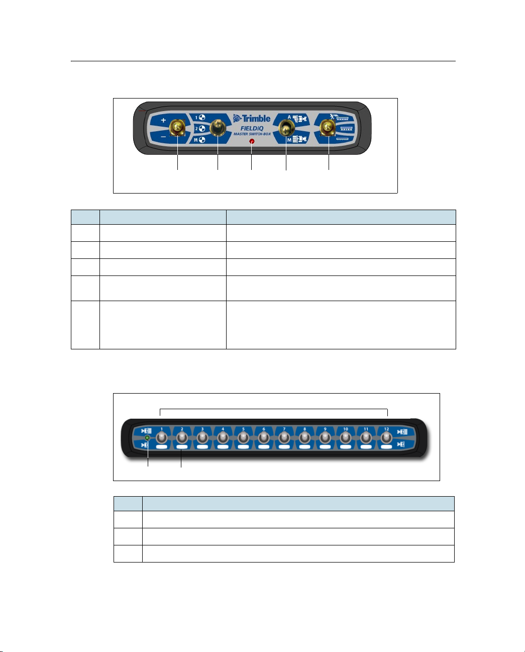
Field-IQ master switch box
c
de
f
g
d
e
c
Item Position
Increment/decrement switch
c
Rate switch Rate 1, Rate 2, Manual Rate
d
LED indicator
e
Automatic/Manual section
f
switch
Master switch Off, On, Jump Start position.
g
You can switch from Automatic to Manual mode while
traveling.
Use the jump start function if you lose a GPS signal or
you want to start applying before your implement is up
to speed.
Field-IQ 12-section switch box (optional)
Item
LED indicator
c
Section switches
d
Space to write which row the switch controls.
e
EZ-Guide 500 Lightbar Guidance System Release Notes 7
Page 8
Enabling the Field-IQ system
1. From the main guidance screen, select the icon and then press .
The Configuration screen appears.
2. Make sure that the user mode is set to Advanced.
3. Select Application Control / Controller Settings / Field-IQ:
4. Select an application controller mode. The options are:
– Row Crop Planting, see Setting up Field-IQ planting, page 8
– Liquid, see Setting up Field-IQ liquid application, page 13
– Granular, see Setting up Field-IQ granular application, page 19
– Spreading, see Setting up Field-IQ spreading, page 24
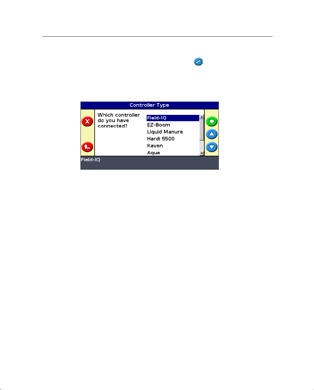
Setting up Field-IQ planting
Entering implement measurements
1. In the Controller Type screen, select Field-IQ and then select Row Crop
Planting.
2. Complete the Setup wizard to enter the implement measurement values:
– Number of Rows
– Row Spacing
– Implement Mount Type
8 EZ-Guide 500 Lightbar Guidance System Release Notes
Page 9
– Hitched / 3pt
– Drawbar
– Forward/Back Offset
– Capacity
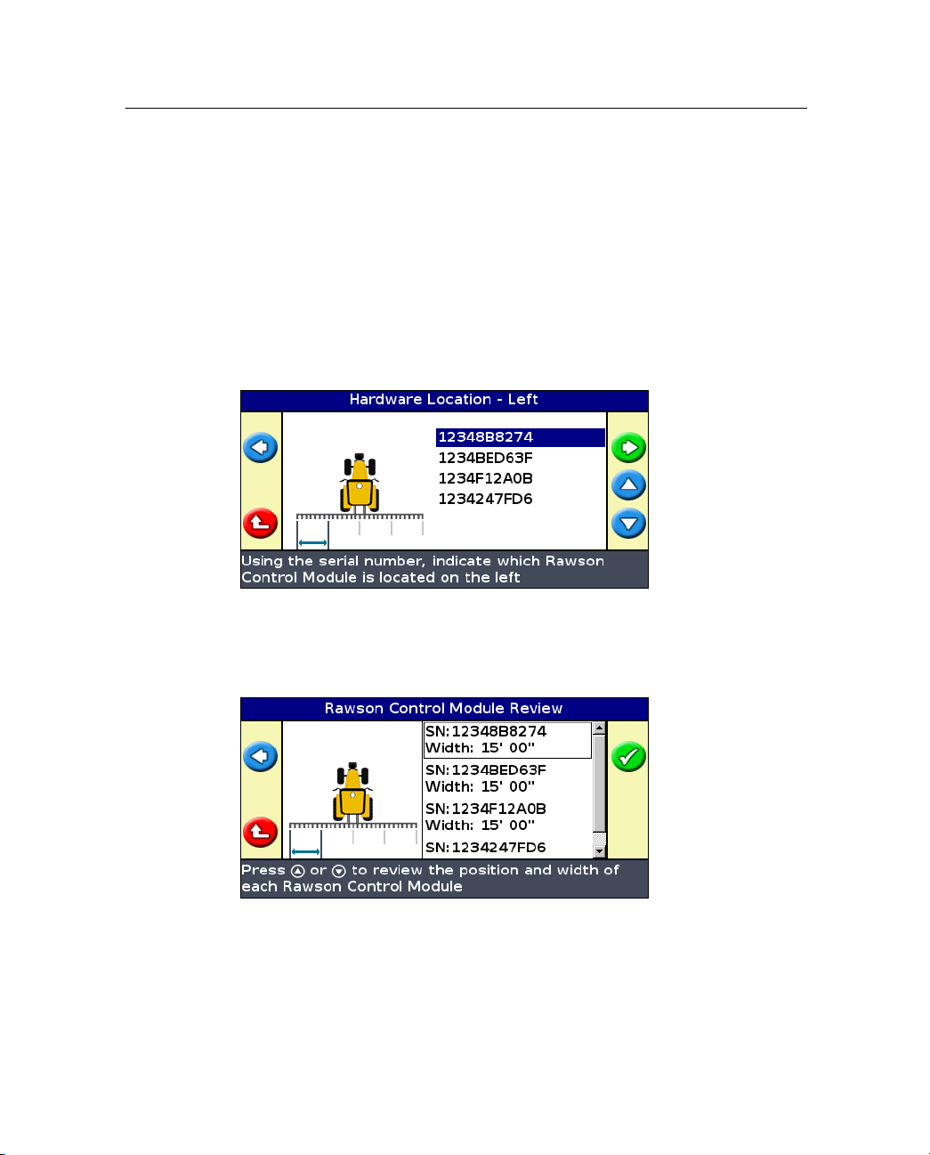
Setting up the Rawson control modules
1. Use the module serial numbers to indicate where each module can be
found on the planter:
2. Enter the width of each section.
The Rawson Control Module Review screen is informational and shows the
serial number and width of each module:
EZ-Guide 500 Lightbar Guidance System Release Notes 9
Page 10
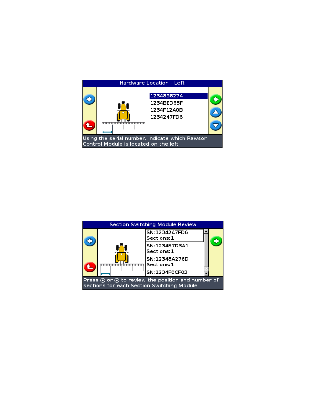
Setting up the Field-IQ section control modules
1. Using the module serial numbers, indicate where each Field-IQ module
can be found on the planter:
2. Enter the number of sections each controller module will control.
3. Select the boom switching mode:
– Liquid Boom
– Tru Count
The Section Switching Module Review screen is informational and shows
the serial number and width of each module:
4. Enter the width of each section.
10 EZ-Guide 500 Lightbar Guidance System Release Notes
Page 11
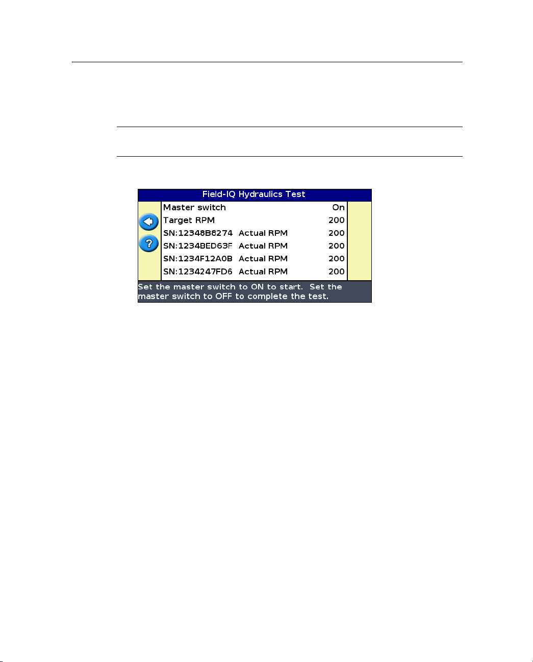
Performing the Field-IQ hydraulics test
1. Enter the target RPM.
CAUTION – When you turn the master switch on, parts of the implement will
C
move.
2. Turn the master switch on. The hydraulics test begins:
3. Turn the master switch off once the test is complete.
Note – If the motors did not achieve the desired RPM, you must alter the hydraulic
setup. Refer to the Field-IQ Installation Instructions or Rawson Installation
Instructions.
Calibrating the Rawson control modules and rate controller
1. Enter the jump start speed. This setting controls the speed to be used
when the Field-IQ master switch is put in the jump start position.
2. Enter the number of seeds per disk for your planter.
3. Do one of the following:
– If you know the gear ratio for your implement, enter it into the
Calibrate Rate Controller screen.
– If you do not know the gear ratio for your implement, use the gear
ratio calculator.
EZ-Guide 500 Lightbar Guidance System Release Notes 11
Page 12
4. Enter the calibration constant. In the planting application, the calibration
constant defaults to 1. When you have completed the seed drop test
(Step 7 through Step 9), you may need to adjust this value.
5. Enter the target rate, target speed, and number of revolutions.
Note – The higher the number of revolutions the more accurate the calibration;
Trimble recommends 5 to 10 revolutions.
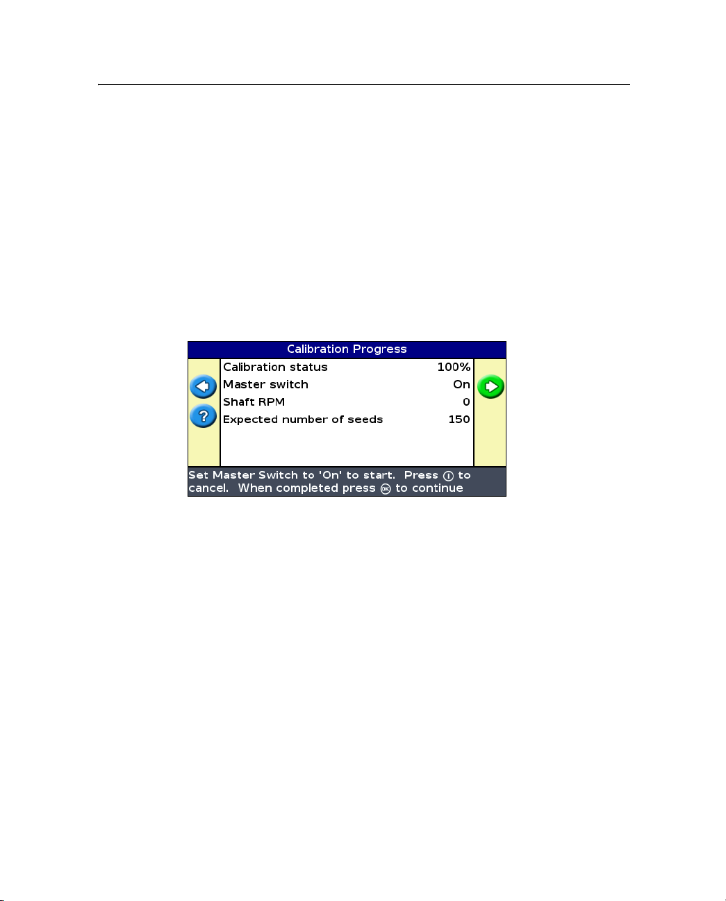
6. To prime the system, select
Yes.
7. To begin calibration, turn the master switch on.
The Calibration Progress screen is informational and indicates the status
of the calibration:
8. Turn the master switch off.
9. Count the number of seeds dropped from one row unit and then enter the
number.
10. If required, adjust the Verify Rate and Speed Range. The system
automatically calculates the fastest and slowest speed that will allow you
to successfully achieve these numbers.
11. The next two screens are informational and show the operating speed
ranges for your target rates.
Note – If speed limits are not within the required range, alter the gear ratio.
12 EZ-Guide 500 Lightbar Guidance System Release Notes
Page 13

12. In the Apply Calibration screen, do one of the following:
– Select Yes to apply the calibration data from the current rate
controller to the remaining rate controllers.
– Select No to calibrate each controller separately.
Setting up Field-IQ liquid application
Entering implement measurements
1. In the Controller Type screen, select Field-IQ and then select Liquid.
2. Complete the Setup wizard to enter the implement measurement values:
– Number of rows
– Row spacing
– Implement Mount Type
Hitched / 3pt
Drawbar
– Forward/Back Offset
– Capacity
EZ-Guide 500 Lightbar Guidance System Release Notes 13
Page 14

Setting up the Rawson control modules
1. Use the module serial numbers to indicate where each module can be
found on the planter:
2. Enter the width of each section.
The Rawson Control Module Review screen is informational and shows the
serial number and width of each module:
14 EZ-Guide 500 Lightbar Guidance System Release Notes
Page 15

Setting up the Field-IQ section control modules
1. Using the module serial numbers, indicate where each Field-IQ module
can be found on the planter:
2. Enter the number of sections each controller module will control.
3. Select the boom switching mode:
– Liquid Boom
– Tru Count
The Section Switching Module Review screen is informational and shows
the serial number and width of each module:
4. Enter the width of each section.
EZ-Guide 500 Lightbar Guidance System Release Notes 15
Page 16

Performing the Field-IQ hydraulics test
1. Enter the target RPM.
CAUTION – When you turn on the master switch, parts of the implement will
C
move.
2. Turn on the master switch. The hydraulics test begins:
3. Turn off the master switch once the test is complete.
Note – If the motors did not achieve the desired RPM, you must alter the hydraulic
setup. Refer to the Field-IQ Installation Instructions or Rawson Installation
Instructions.
Calibrating the Rawson control modules and rate controller
1. Enter the jump start speed. This setting controls the speed to be used
when the Field-IQ master switch is put in the jump start position.
2. Do on of the following:
– If you know the gear ratio for your implement, enter it into the
Calibrate Rate Controller screen.
– If you do not know the gear ratio for your implement, use the gear
ratio calculator.
16 EZ-Guide 500 Lightbar Guidance System Release Notes
Page 17

3. Enter the pump constant. This is the amount of liquid pumped in one
revolution. See the pump manufacturer's instructions for this value:
Note – Leaving the value at 0 prompts the system to auto calibrate.
4. Enter the target rate, target speed, and number of revolutions.
Note – The higher the number of revolutions the more accurate the calibration;
Trimble recommends 5 to 10 revolutions.
5. To prime the system, select
Yes.
6. To begin calibration, turn the master switch on.
The Calibration Progress screen is informational and indicates the status
of the calibration:
7. Turn the master switch off.
EZ-Guide 500 Lightbar Guidance System Release Notes 17
Page 18

8. Perform the calibration three (3) times. Enter the average amount of
liquid dispensed for the three calibration tests:
9. In the Calibration OK? screen, do one of the following:
– Select Yes to end the calibration.
– Select No to return to the Pump Constant screen.
10. If required, adjust the Verify Rate and Speed Range. The system
automatically calculates the fastest and slowest speed that will allow you
to successfully achieve these numbers.
11. The next two screens are informational and show the operating speed
ranges for your target rates.
Note – If speed limits are not within the required range, alter the gear ratio.
12. In the Apply Calibration screen, do one of the following:
– Select Yes to apply the calibration data from the current rate
controller to the remaining rate controllers.
– Select No to calibrate each controller separately.
18 EZ-Guide 500 Lightbar Guidance System Release Notes
Page 19

Setting up Field-IQ granular application
Entering implement measurements
1. In the Controller Type screen, select Field-IQ and then select Granular.
2. Complete the Setup wizard to enter the implement measurement values:
– Implement Width
– Implement Mount Type
Hitched / 3pt
Drawbar
– Forward/Back Offset
– Capacity
EZ-Guide 500 Lightbar Guidance System Release Notes 19
Page 20

Setting up the Rawson control modules
1. Use the module serial numbers to indicate where each module can be
found on the planter:
2. Enter the width of each section.
The Rawson Control Module Review screen is informational and shows the
serial number and width of each module:
20 EZ-Guide 500 Lightbar Guidance System Release Notes
Page 21

Setting up the Field-IQ section control modules
1. Using the module serial numbers, indicate where each Field-IQ module
can be found on the planter:
2. Enter the number of sections each controller module will control.
The Section Switching Module Review screen is informational and shows
the serial number and width of each module:
3. Enter the width of each section.
EZ-Guide 500 Lightbar Guidance System Release Notes 21
Page 22

Performing the Field-IQ hydraulics test
1. Enter the target RPM.
CAUTION – When you turn on the master switch parts of the implement will
C
move.
2. Turn on the master switch. The hydraulics test begins:
3. Turn off the master switch once the test is complete.
Note – If the motors did not achieve the desired RPM, you must alter the hydraulic
setup. Refer to the Field-IQ Installation Instructions or Rawson Installation
Instructions.
Calibrating the Rawson control modules and rate controller
1. Enter the jump start speed. This setting controls the speed to be used
when the Field-IQ master switch is put in the jump start position.
2. Enter the density of the material to apply.
3. Do one of the following:
– If you know the gear ratio for your implement, enter it into the
Calibrate Rate Controller screen.
– If you do not know the gear ratio for your implement, use the gear
ratio calculator.
4. Enter the calibration constant.
5. Enter the target rate, target speed, and number of revolutions.
22 EZ-Guide 500 Lightbar Guidance System Release Notes
Page 23

Note – The higher the number of revolutions the more accurate the calibration;
Trimble recommends 5 to 10 revolutions.
6. To prime the system, select
Yes.
7. To begin calibration, turn the master switch on.
The Calibration Progress screen is informational and indicates the status
of the calibration:
8. Turn the master switch off.
9. Enter the weight of the material that was dropped by the spreader.
10. If required, adjust the Verify Rate and Speed Range. The system
automatically calculates the fastest and slowest speed that will allow you
to successfully achieve these numbers.
11. The next two screens are informational and show the operating speed
ranges for your target rates.
Note – If speed limits are not within the required range, alter the gear ratio.
12. In the Apply Calibration screen, do one of the following:
– Select Yes to apply the calibration data from the current rate
controller to the remaining rate controllers.
– Select No to calibrate each controller separately.
EZ-Guide 500 Lightbar Guidance System Release Notes 23
Page 24

Setting up Field-IQ spreading
Entering implement measurements
1. In the Controller Type screen, select Field-IQ and then select Spreading.
2. Complete the Setup wizard to enter the implement measurement values:
– Implement Width
– Implement Mount Type
Hitched / 3pt
Drawbar
– Forward/Back Offset
– Capacity
24 EZ-Guide 500 Lightbar Guidance System Release Notes
Page 25

Setting up the Rawson control modules
1. Use the module serial numbers to indicate where each module can be
found on the planter:
2. Enter the width of each section.
The Rawson Control Module Review screen is informational and shows the
serial number and width of each module:
EZ-Guide 500 Lightbar Guidance System Release Notes 25
Page 26

Setting up the Field-IQ section control modules
1. Using the module serial numbers, indicate where each Field-IQ module
can be found on the planter:
2. Enter the number of sections each controller module will control.
The Section Switching Module Review screen is informational and shows
the serial number and width of each module:
3. Enter the width of each section.
26 EZ-Guide 500 Lightbar Guidance System Release Notes
Page 27

Performing the Field-IQ hydraulics test
1. Enter the target RPM.
CAUTION – When you turn on the master switch, parts of the implement will
C
move.
2. Turn on the master switch. The hydraulics test begins:
3. Turn the master switch off once the test is complete.
Note – If the motors did not achieve the desired RPM, you must alter the hydraulic
setup. Refer to the Field-IQ Installation Instructions or Rawson Installation
Instructions.
Calibrating the Rawson control modules and rate controller
1. Enter the jump start speed. This setting controls the speed to be used
when the Field-IQ master switch is put in the jump start position.
2. Enter the gate height, gate width and spreader belt length per revolution.
3. Enter the density of the material to apply.
4. Do on of the following:
– If you know the gear ratio for your implement, enter it into the
Calibrate Rate Controller screen.
– If you do not know the gear ratio for your implement, use the gear
ratio calculator.
EZ-Guide 500 Lightbar Guidance System Release Notes 27
Page 28

The spreader constant calculates automatically. You can adjust the value
if required—follow the on-screen instructions:
5. Enter the target rate, target speed, and number of revolutions.
Note – The higher the number of revolutions the more accurate the calibration;
Trimble recommends 5 to 10 revolutions.
6. To prime the system, select
Yes.
7. To begin calibration, turn the master switch on.
The Calibration Progress screen is informational and indicates the status
of the calibration:
8. Turn the master switch off.
9. Enter the weight of the material that was dropped by the spreader.
10. If required, adjust the Verify Rate and Speed Range. The system
automatically calculates the fastest and slowest speed that will allow you
to successfully achieve these numbers.
28 EZ-Guide 500 Lightbar Guidance System Release Notes
Page 29

11. The next two screens are informational and show the operating speed
ranges for your target rates.
Note – If speed limits are not within the required range, alter the gear ratio.
12. In the Apply Calibration screen, do one of the following:
– Select Yes to apply the calibration data from the current rate
controller to the remaining rate controllers.
– Select No to calibrate each controller separately.
Using the Field-IQ system
1. From the main guidance screen, select and then create a new field or
select an existing field.
2. Select the Refill icon to:
– adjust the current bin volume
– select the refill method
– refill bin now
3. Select the Refill icon to adjust:
– Swath Control Setup
Select Liquid Boom when using Liquiblock valves, or select Tru Count
no Inverter when using Tru Count clutches. (Use the following screens
to configure the Boom Switching Mode.)
– Boom Switching Mode
Select Liquid Boom when using Liquiblock valves, or select Tru Count
no inverter when using Tru Count clutches.
– Boundary Switching Overlap
4. Select Application Setup to:
– Turn rate control on or off.
– Adjust target rate 1.
– Adjust target rate 2.
EZ-Guide 500 Lightbar Guidance System Release Notes 29
Page 30

– Adjust the rate increment.
– Turn rate snapping on or off.
– Adjust the jump start speed.
5. Select Boundaries to select:
– Enabled
– Disabled for This Field
– Disabled for All Fields
Expanded third party variable rate controller compatibility
The EZ-Guide 500 system now supports the following variable rate controllers:
• Amazone Amatron+
• LH Agro LH5000
Variable rate functionality can only be accessed when the user mode is set to
Advanced. When a compatible rate controller is connected, the EZ-Guide 500
system uses a prescription map to send application rate commands to the
controller. Once this happens, the controller changes to the appropriate rate,
as instructed by the lightbar.
These variable rate controllers connect through the COM connection on the
EZ-Guide 500 lightbar guidance system.
This function requires the variable rate unlock.
30 EZ-Guide 500 Lightbar Guidance System Release Notes
Page 31

GPS position quality indicator
You can now select the level of GPS quality that you want the system to use.
This gives you the option of extending your operating hours by running the
system when GPS satellites are less available and possibly providing lower
position quality. Alternatively, you can select the best level of quality in order to
achieve the maximum accuracy for each correction type.
The bars on the GPS position quality indicator represent the overall quality of
the position. The quality is determined by factoring satellite availability,
health, and a calculated accuracy estimate. The more green bars shown, the
higher the level of GPS position quality.
A black bracket under the GPS signal bars indicates the quality level you
selected:
Bars Option Select ...
Favor Accuracy For operations that require the highest accuracy, such
as row crop planting or strip-till applications.
Note – Trimble recommends this option for the best
pass-to-pass and year-to-year repeatability. This option
is equivalent to the quality level of previous versions of
the EZ-Guide firmware.
EZ-Guide 500 Lightbar Guidance System Release Notes 31
Page 32

Bars Option Select ...
Balanced Quality To trade potential accuracy for a slight increase in
production time.
Favor Availability To extend production time further, with more
potential for reduced accuracy.
Note – This option sometimes trades some accuracy
for more availability or runtime. This option may still
achieve the highest level of accuracy that is applicable
for your correction source. If you select this option
when using RTK corrections, the system may use
positions that are greater than 1'' pass-to-pass
accuracy.
To adjust the GPS position quality indicator, go to Configuration / SBAS,
OmniStar, or RTK.
Krohne Liquid manure flow meter support
The EZ-Guide 500 Lightbar Guidance System now supports the Krohne
liquid/slurry electromagnetic flow meter for as-applied mapping of manure
applications.
You need an EZ-Guide 500 to Krohne interface cable (P/N 78369) to connect
the two devices.
Liquid manure application, tracking, and reporting
The EZ-Guide 500 lightbar guidance system now allows you to generate liquid
manure handling records to satisfy regulatory requirements. Use this option to
easily track the location of the area covered, along with the volume per area
and other important data points.
When this feature is enable and connected to a flow meter, the EZ-Guide
system records the actual rate from the flow meter that is being applied for
each field. These values will then appear as an as-applied coverage map in the
32 EZ-Guide 500 Lightbar Guidance System Release Notes
Page 33

Summary Report for that field. When you are finished, you can transfer the
Summary Report to a computer through a USB connection or import the field
data into the EZ-Office
®
software.
Setting up Krohne support
Before setup, the guidance screen appears as follows. Note that there is no
application bar:
1. Make sure that User Mode is set to Advanced.
2. Go to the Application Control option and from the Application Control
menu, select Controller Settings.
3. Select Liquid Manure:
EZ-Guide 500 Lightbar Guidance System Release Notes 33
Page 34

4. Enter the pulses per gallon that the flow meter outputs—for more
information, refer to the flow meter's configuration display or the user
documentation. A common measurement is one pulse per gallon:
The system is now configured to read information from the flow meter.
Read the information on this screen before continuing:
5. Select Ta rg et Rat e. The target rate is the rate you want to achieve through
varying the speed of the vehicle or through altering the pump pressure or
volume:
34 EZ-Guide 500 Lightbar Guidance System Release Notes
Page 35

6. Scroll up or down to achieve the required rate and then select OK:
7. Confirm that the screen shows the correct rate. Press the
return to the guidance screen:
I button twice to
EZ-Guide 500 Lightbar Guidance System Release Notes 35
Page 36

The guidance screen now shows the application bar at the bottom:
T = target rate
A = actual rate. Reported
in gallons per acre when
vehicle is moving
F = flow rate. Reported
in gallons per minute when
vehicle is stationary.
36 EZ-Guide 500 Lightbar Guidance System Release Notes
Page 37

Application bar
c
d
e
Item Description
Flow/application indicator The wheel spins when flow meter pulses are detected.
c
Boom section status indicator Change color to show the current state of each boom
d
Auto/manual switching
e
indicator
section:
• Green: The boom section is enabled and applying
product.
• Orange: The boom section is enabled but not
currently applying.
• Red: The section is off (no flowmeter pulses
detected).
Shows which switching mode the controller is in.
• When the system is in manual switching mode, the
indicator is gray.
• When the system is in automatic switching mode,
the indicator is in color.
EZ-Guide 500 Lightbar Guidance System Release Notes 37
Page 38

EZ-Boom granular fertilizer spreading
The EZ-Guide 500 lightbar guidance system now supports granular fertilizer
application with the EZ-Boom system. Using a rate sensor and a Servo or
PWM control valve, you can control a single product on a pull-type or
self-propelled spreader.
The granular spreading feature allows you to select a jump start speed to
compensate when operating under a low GPS signal.
This feature is available from Controller Settings / EZ-Boom.
Upgrade procedure
Installing additional language packs
CAUTION – Do not add language packs to the lightbar when the internal
C
memory is nearly full (less than 15 hours remaining). To free up internal memory,
save all of the data to a USB drive and then copy the data on the drive to an
office computer. Delete the field data from the internal memory. Install the
language packs and then, if necessary, use the drive to replace the field data in
the lightbar’s internal memory.
A number of language packs are available as a web release. Language packs are
loaded onto the lightbar from a USB drive:
1. Transfer the required language pack (.lpf file) from
www.ez-guide.com to an office computer.
2. Copy the language pack to a USB drive and then insert the USB drive into
the USB port on the lightbar. Make sure the files are copied to the root of
the USB drive, not to any folders on the USB drive.
3. Turn on the lightbar.
38 EZ-Guide 500 Lightbar Guidance System Release Notes
Page 39

4. Select the main guidance screen and then wait for up to 1 minute. The
language pack is automatically detected:
5. Press to load the language pack(s).
Once the language pack is installed, the language selection screen
appears.
6. Select the language you require:
EZ-Guide 500 Lightbar Guidance System Release Notes 39
Page 40

Upgrading the firmware
CAUTION – Do not upgrade the lightbar’s firmware when the internal memory is
C
nearly full (less than 15 hours remaining). If you do, the lightbar may lose your
current settings. Before upgrading the firmware, save the lightbar’s settings and
the data to a USB drive and then transfer all of the data on the drive to an office
computer. If necessary, use the drive to replace the field data in the lightbar’s
internal memory after the upgrade is complete.
Note – Before upgrading to version 5.10 of the EZ-Guide 500 system, make sure
™
that you are using the AgGPS Autopilot
or later.
Before you begin to update the firmware in the lightbar, check which firmware
version is currently installed:
1. Select Configuration / About the EZ-Guide.
2. Check the Vers ion number:
automated steering system version 4.52
This is the firmware version. If the number is 4.05.xxx.x, you have firmware
version 4.05. If the number is 5.10.xxx.x, you already have firmware version 5.10.
To upgrade the lightbar to version 5.10:
1. Download the firmware version 5.10 upgrade file from www.EZ-
Guide.com to your office computer.
2. Extract the contents to the USB drive. Make sure the files are copied to
the root of the USB drive, not to any folders on the USB drive.
3. Insert the USB drive in the lightbar.
40 EZ-Guide 500 Lightbar Guidance System Release Notes
Page 41

4. Turn on the lightbar.
When the USB drive is detected, the lightbar runs the upgrade wizard
automatically.
If you currently have firmware version 4.05 or earlier, the firmware version
5.10 upgrade file appears:
CAUTION – Do not turn the lightbar off while the firmware is being updated.
C
This could render the lightbar inoperable.
5. Select the EZ-Guide firmware .img file and then press . The wizard
installs the monitor file and the firmware version 5.10. When the
firmware is installed, the lightbar restarts.
The lightbar firmware is upgraded to version 5.10.
Note – When upgrading to this new firmware, the previously set SNR and
Elevation Mask GPS settings remain active until you next turn off and then turn
on the lightbar.
EZ-Guide 500 Lightbar Guidance System Release Notes 41
Page 42

42 EZ-Guide 500 Lightbar Guidance System Release Notes
 Loading...