

Page 1

Trimble DiNi® 12, 12T, 22
Short Form User Guide
PN 571 703 081
www.trimble.com
Page 2

Page 3

Introduction
Welcome to DiNi
By purchasing a Digital Level from Trimble
have opted for a leading-edge product in the field
of surveying instruments.
We congratulate you on your choice and would
like to thank you for the trust placed in our company.
These abridged instructions are intended to serve
as start-up aid for you. Please find more detailed
descriptions in the full Operating Instructions.
Good luck.
®
you
3
Page 4

Safety Notes
Do not point the telescope directly at the sun.
Do not use the instrument and accessories in
rooms with danger of explosion.
Operate the instrument only in the compliance
with the operating conditions specified.
Protect operator and instrument sufficiently at the
site of measurement (e.g. construction site, roads,
etc.). Observe any relevant national regulations and
the Road Traffic Act.
Tread tripod legs firmly into the ground to prevent
sinking in and falling over of the instrument by wind
pressure.
Mount the instrument to the tripod using the
tripod screw immediately after you take the instrument from its case. Never leave the instrument
placed loosely only on the tripod head. After loosening the tripod screw, immediately store the instrument in its case.
Don’t make any changes or repairs on the instru-
ment and accessories. This must be done only by a
service team or by authorised technical staff.
4
Page 5

Safety Notes
When you work with staves in the vicinity of elec-
tric plants (e.g. electric railways, aerial lines, transmitting stations, etc.) your life is acutely endangered.
This risk exists independent of the staff material (e.g.
aluminium or wood). In such cases it is necessary to
inform the competent and authorised safety authorities and observe their instructions.
Don't use the instrument too long when it is rain-
ing. During breaks, cover the instrument with the
protective hood. Wipe the instrument and case dry in
the field and let it dry completely indoors, with the
case open.
In a thunderstorm, don't carry out surveying work
to avoid being struck by a lightning.
Remove the batteries in case of unloading or a
longer time without using the instrument. Recharge
the batteries with Single Battery Charger.
Properly dispose of the batteries and equipment
taking into account the applicable national regulations. Prevent improper use of the disposed instrument by proper disposal.
5
Page 6

Safety Notes
Before every use of the instrument, verify that it is
in perfect condition, particularly after longer transportation, fall or any other improper use. Systematic
check measurements particularly before and after
extensive surveying projects will help to avoid erroneous measurements.
Do not operate the battery charger and PC Card
reader in humid conditions (risk of electrical shock).
Make sure the voltage setting is identical on the
battery charger and voltage source. Do not use instruments while they are wet.
The magnetic PC Card cover should always be in
place to stop environment damage (water, dust).
Do not use destroyed plugs and cables for accesso-
ries with the instrument.
6
Page 7

Environmental information
NOTICE FOR TRIMBLE'S EUROPEAN UNION CUSTOMERS
Trimble is pleased to announce a new recycling
program for our European Union customers. At
Trimble, we recognize the importance of
minimizing the environmental impacts of our
products. We endeavor to meet your needs, not
only when you purchase and use our products,
but also when you are ready to dispose of them.
That is why Trimble is actively pursuing, and will
continue to pursue, the expanded use of
environmentally friendly materials in all its
products, and why we have established a
convenient and environmentally friendly recycling
program.
As Trimble makes additional recycling facilities
available for your use, we will post their locations
and contact information to our Recycling
Instructions web page.
For product recycling instructions and more information, please go to
http://www.trimble.com/environmentT
Recycling in Europe:
To recycle Trimble WEEE,
Call +31 497 53 2430, and ask for the “WEEE
Associate” Or Mail a request for recycling
instructions to:
7
Page 8

Environmental information
Trimble Europe BV
c/o Menlo Worldwide Logistics
Meerheide 45
5521 DZ Eersel, NL
8
Page 9

Contents
Introduction................................................... 3
Safety Notes................................................... 4
Environmental Information............................. 7
Contents ........................................................ 9
Hardware overview....................................... 10
Software overview DiNi
Software overview DiNi
12,22..................... 12
12T........................ 13
Setting up and switching on......................... 14
The control panel ......................................... 15
Preparing for measurement .......................... 16
Projects and inputs....................................... 20
Line levelling ................................................ 22
Line interruption........................................... 24
Line adjustment............................................ 26
Reference Heights in the Memory ................. 28
Data Transfer ............................................... 29
Data Memory PCMCIA Card.......................... 31
Adjustment .................................................. 32
Accessories for DiNi
.................................... 35
Updates ....................................................... 36
Maintenance and Care ................................. 37
9
Page 10
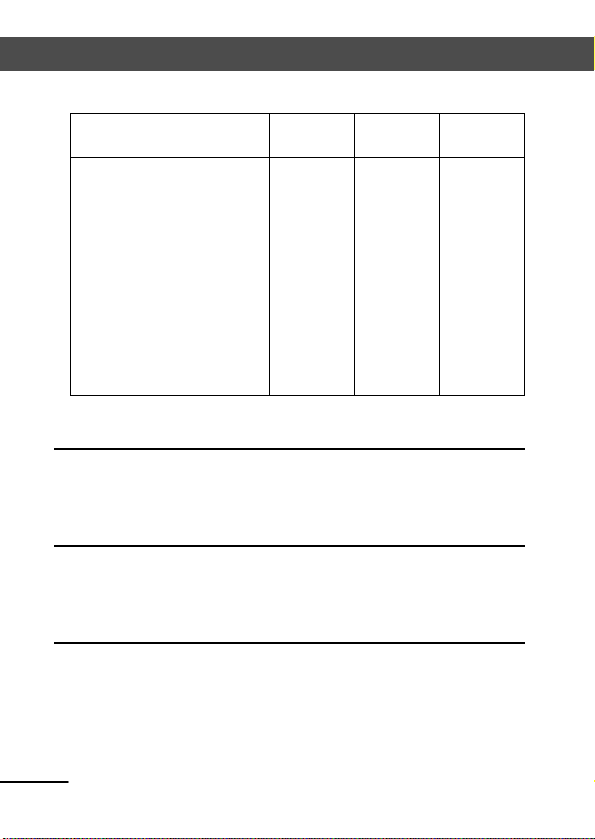
Hardware overview
Standard deviation as
per DIN 18723
Standard deviation on
1 km of double
levelling
Electronic measurement:
- invar precision
barcode staff
- foldable bar code staff
Visual measurement:
- foldable staff,
metric scale
DiNi
12
- Graduated circle, external
- Exchangeable PCMCIA Card
DiNi
12 T
- Elektronic circle
- Exchangeable PCMCIA Card
DiNi
22
12 DiNi 22 DiNi12T
DiNi
0.3 mm
1.0 mm
1,5 mm
0.7 mm
1.3 mm
2.0 mm
0.3 mm
1.0 mm
1,5 mm
- Graduated circle, external
- Internal data memory
10
Page 11
15 16 14
3
6
10 7 5
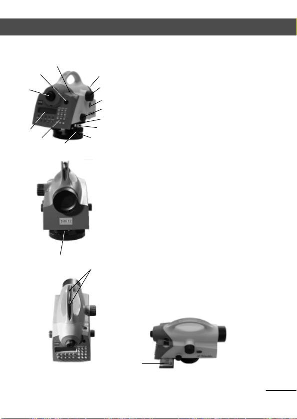
Hardware overview
13
12
11
9
8
1 Telescope objective with integrated
sunshield
2 Telescope focusing control
1
3 Trigger key for measurement
2
4 Horizontal tangent screw
4
(endless slow motion drive)
5 Graduated circle, external
6 PCMCIA Card plug-in module
(DiNi
(DiNi
®
12, 22)
®
12, 12 T)
7 Tribrach
8 Footscrews
9 Keyboard
10 Display
11 Eyepiece
12 Window for circular bubble
13 Cap, to be removed for adjustment of
circular bubble
14 Battery compartment
15 15 Sight vane (notch and bead sights)
16 PCIMCIA Card in the plug-in module
(DiNi
®
12, 12 T)
11
Page 12
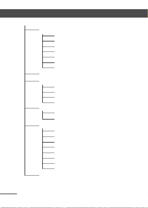
Software overview DiNi 12,22
1 Input
1 max. sighting distance
2 min. sighting height
3 max. station difference
4 Refraction coefficient
5 Addition constant (offset)
6 Date (DiNi
7 Time (DiNi
2 Adjustment
3 Data transfer
1 Interface 1
2 Interface
3 PC-Demo
4 Update/Service
4 Setting of recording
1 Recording data
2 Parameter setting
5 Instrument settings
1 Height
2 INP function
3 Display L
4 Shut off
5 Acoustic signal
6 Language
7 Date (DiNi
8 Time (DiNi
6 Line adjustment (DiNi
12)
12)
12)
12)
12)
12
Page 13

Software overview DiNi 12T
1 Input
.......
2 Adjustment
.......
3 Data transfer
.......
4 Setting of recording
.......
5 Instrument settings
1 Display L
2 Display E
3 Shut off
4 Acoustic signal
5 Language
6 Contrast
6 Set instrument units
1 Height in
2 INP function
3 Direction in
4 Coordinate System
5 Coordinate Display
6 Data
7 Time
7 Line adjustment
........ DiNi
12 and 22
13
Page 14

2
2 2
Setting up and switching on
Set-Up
Set up the tripod securely
Remove instrument from container
Place instrument on tripod and screw down
tightly (tripod retaining screw)
Move bubble into the centre of the circular level
(tripod foot screws)
Switching on
1
1
ON/OFF
Press button
Requirements: Battery charged
Memory Card inserted
14
Page 15

The control panel
DiNi 12 and DiNi 22
Switching
on/off
DiNi
12T
Main menu
Messen
Measurment
Editor
Main menu
Switching
on/off
Measurement
Editor
Measure mode
15
Page 16

Preparing for measurement
Setting recording
Start Screen
7 MENU
Call up Main Menu:
Select from menus in this way
Yes
ESC
MOD
Scroll through menu
Select marked entry
Return to previous menu
or
Change entry
or
Change softkeys
Yes
4 SET REC. PARAM.
16
Page 17

Preparing for measurement
The following settings are requirements for subsequent line adjustment!
DiNi® 12 and 22 only:
Ja Yes
MOD
ESC
1 RECORDING OF DATA
2 RECORD PC Card or iMEM
3 ROD READINGS RMC
Return
DiNi® 12T only:
Ja Yes
MOD
ESC
1 RECORDING OF DATA
2 RECORD PC Card
Return
and
+- TS-M
MOD
MOD
ESC
Set Measure Mode
1 MODE Level
2 REG:- DATA R,HD,Z
Return
17
Page 18

Preparing for measurement
Intermediate sight Stake out
Without reference height
MEAS
Initiate measurement – Repeatable as often as desired
Staff reading Horizantal distance
With reference height
Intm
Start intermediate sight
Input benchmark height:
o.k.
Enter counter values in this way
0,1,....9
o.k.
MEAS
o.k.
Use number keys
Correct input
Confirm input
Measure backsight point
Confirm measured value
18
Page 19

Preparing for measurement
Height difference
to the Backsight
point
Height of the particular point
9 DISP
Browse values
A: Further measurements
B: Return
Stake out the height of a point
SOut
o.k.
MEAS
o.k.
Start staking out
Input benchmark height
Carry out backsight measurement
Confirm nominal value
Input nominal elevation
o.k.
MEAS
Actual height of point to be staked out
Nominalactual
deviation
9 DISP
o.k.
Initiate measurement
Browse values
Repeat until dz is sufficiently small
A: Further nominal elevations
B: Return
Visual rodreading
19
Page 20

Projects and inputs
Generating a new project (DiNi 12 and 12T only)
Call up edit mode
6 EDIT
Select project management
PRJ
Yes
Input name
o.k.
Switch to
Project name
ESC
Present
character set
20
Page 21

Projects and inputs
Input alphanumeric characters in this way
abc, ABC
NUM
DIST.
MEAS
0,1,....9
o.k.
Switch to small, large,
,
numeric
Browse character set
Browse character set
Number keys for characters
Correct input
Confirm input
21
Page 22

Line levelling
Start a new line
Line
n ew line
o.k.
o.k.
o.k.
o.k.
o.k.
Input line number
Select sequence of measurem.
Input benchmark height
Input point number and point code
New line
Procedure:B/F etc.
Alternate:yes/no
22
Page 23

Line levelling
Measuring back and foresights
Height of line of sight
MEAS
backsight
Staff reading
backsight
MEAS
Foresight
Wdhl
Ending line
LEnd
Yes
etc.
Repeat measurement
Specify end of line as a benchmark height
Next sight
Repeat
DISP
Browse values
Overall height
difference
Nominal-actual
deviation
Total
back/foresight
distances
23
Page 24

Line interruption
Intermediate sight on the line
Intermediate sight Stake out
IntM
MEAS
ESC
Start intermediate sight
Initiate measurement
Return
Staking out a height on the line
SOut
o.k.
MEAS
o.k.
ESC
Start staking out
Input nominal elevation
Initiate measurement
Confirm result
Continue with next height to be staked out
Return
Continue with last line
Line
Select option
Continue
with line
levelling
24
Page 25

Line interruption
Continuing with a line from another project
6 EDIT
Call up
project,
confirm
project
Cont. Line
of Project
Select
Option
?PNo
?Cod
?Adr
?LNo
o.k.
Continue
with line
levelling
Search for start line
Confirm end of line
25
Page 26

Line adjustment
DiNi 12 and 12T only
Line adjustments can only be performed if the
levelling line has been completed and saved on
the memory along with the intermediate heights.
In line levelling, a line is linked to points with
known heights at the beginning and at the end
so that the measured height difference can be
compared with the nominal height difference.
The "line adjustment" program allows to spread
the occurring difference over the individual staff
stations proportionally to the sighting distances,
obtaining adjusted heights as result.
7 MENU
Yes
Search for start of line
i.e.
?ZNr
o.k.
26
Page 27

Line adjustment
End of line is automatically found
o.k.
Yes
Input
benchmark
heights
o.k.
Start
Mark changed
data
End line adjustment
ESC
27
Page 28

Reference Heights in the Memory
Besides entering of data it is possible to call up
the stored data from the memory for line levelling
and Staking out.
Call up the data in this way.
Select project
PRJ
?
?PNr
?Code
?Adr
o.k.
To search in memory using specified criteria
Search for:
Point number, point code or address
Confirm the height
28
Page 29

Data Transfer
Cable for Data transfer with Xon/Xoff
protocol:
DiNi
Order number
7081779470000
®
PC cable:
PC Car d Drive
Cable
PMCIA
29
Page 30

Data Transfer
Data transfer via cable
7 MENU
YES
YES
YES
i.e.
all
YES
Select interface
Select transfer direction
Attention !
A requirement for transfer are identical parameters on the instrument and the peripheral
device: format, protocol, baud rate, parity and
stop bits.
Start data transfer
30
Page 31

Data Memory PCMCIA Card
Formatting a PC Card
With the DiNi 12 and 12T it is possible to format
a SRAM - PC Card.
7 MENU
YES
YES
YES
Attention !
Make sure to transfer the data stored in the PC
Card to another storage medium beforehand, as
all data in the memory is lost during formatting.
31
Page 32

Adjustment
7 MENU
YES
Different
Methods
with identical result
The instrument adjustment defines the necessary
corrections and correction values for the line sight
of DiNi®, which are required to ensure optimum
measuring accuracy.
Before starting any adjustment, allow the instrument to adapt to the ambient temperature.
Situation
A 1 2 B
Förstner
I
1/3 I 1/3 I 1/3 I
1 A B 2
Nähbauer
I
1/3 I 1/3 I 1/3 I
2 A 1 B
Kukkamäki
I
app. 20m I app. 20m I
32
Page 33

Adjustment
MEAS
o.k.
After the selection of the adjustment method, you
can change the settings of earth curvature and
refraction. This is not possible at another point of
the DiNi® menu system. Changes of earth curvature and refraction settings become effective only
if you adjust the system afterwards. The line of
sight will then be corrected accordingly.
with graphic help
.....
Result
If the new line of sight correction is adopted, the
program requests the checking of the reticule
alignment (for visual reading).
screw below the eyepiece - 1
1
33
Page 34

Adjustment
Adjustment of circular bubble
Check the function of circular bubble:
By turning the instrument 180° round the vertical
axis the circular bubble has to remain within the
circle.
Adjustment of circular bubble:
Remove the screw (2) of the protection cap with
the adjusting tool and detach the protection-cap.
2
Turn the instrument 180°.
J3
J2
Eliminate half the residual deviation of the circular
bubble by means of the tribrach screw and half
by adjusting the circular bubble (J1..3).
J1
Repeat this procedure and check the residual
deviation.
Fix the protection cap again. Make sure that the
rubber joint is placed in the groove.
34
Page 35

Accessories for DiNi
Foldable staff made of wood
length: 3 m or 4 m
Telescopic staff made of aluminium
length: 4 m or 5 m
Special parts and invar tape
made of aluminium, invar and foil
length: 30 cm, 50 cm and 1 m
Invar staff
- small and wide base
- length: 1 m, 2 m and 3 m
- Transport case
- Telescopic support
Battery pack and charger
Memory Card and data transmission cable
35
Page 36

Updates
DiNi PC
Cable:
Ordernumber
708177-
9470.000
Software updates are offered by the manufacturer on Internet sites with reservation as to extensions of the functional range. Surf to our Web
sites. The dealer will be pleased to communicate
the Internet site names, when required.
The updates offered contain the following
functions:
- Update of the instrument computer
- Update of the interface computer (DiNi
®
12 and
DiNi® 12 T only )
- Loading of an additional language (four lan guages can be loaded)
The files loaded from the Internet sites have to be
unpacked and copied on a floppy disk.
For the update processes , the operating system
DOS has to be used in any case.
Additionally to the files required for the update
process, the
update instructions have to be
loaded from the Internet in any case and have to
be observed
strictly. No liability will be assumed
for claims resulting from the non-compliance with
the specification.
In these instructions, all steps are described in
detail. They may contain and explain commands
that differ from the description given here.
36
Page 37

Maintenance and Care
Instructions for Maintenance and Care
Allow sufficient time for the instrument to adjust
to the ambient temperature.
Use a soft cloth to remove dirt and dust from the
instrument.
When working in wet weather or rain, cover the
instrument during longer breaks with the protective hood.
Clean the optics with special care using a clean
and soft cloth, cotton wool or a soft brush, do
not use any liquid except pure alcohol.
Do not touch the optical surface with the fingers.
For transportation over long distances, the instrument should be stored in its case.
When working in wet weather, wipe the instrument and case dry in the field and let it dry completely indoors, with the case open.
Let wet instruments and accessories dry before
packing them up.
After a long storage, check the adjustment of the
instrument prior to use.
Observe the boundary values for the temperature
of storing, especially in the summer (interior of
the vehicle).
37
Page 38

38
Page 39

Page 40

Trimble Engineering and Construction Division
5475 Kellenburger Road
Dayton, Ohio 45424
U.S.A.
800-538-7800 (Toll Free in U.S.A.)
+1-937-233-8921 Phone
+1-937-233-9004 Fax
www.trimble.com
 Loading...