

Page 1

TRENDnet
Rev. 01 Nov., 1999
Printed in Taiwan
6TWH6W1IR.01
RECYCLABLE
TW-H6W1IR
ISDN Router
User’s Guide
Page 2

Page 3

Copyright Statement
Copyright ©1999 TRENDware
No part of this publication may be reproduced in any form or by any
means or used to make any derivative such as translation,
transformation, or adaptation without permission TRENDware, as
stipulated by the United States Copyright Act of 1976.
Trademarks
TRENDnet is a registered trademark of TRENDware.
All other trademarks belong to their respective owners.
TW -H6W1IR ISDN Remote Router
Page 4

TW -H6W1IR ISDN Remote Router
Table of Contents
INTRODUCTION.................................................................................1
Product Features.......................................................................................................2
Applications for your TW-H6W1IR.........................................................................5
Internet Access..........................................................................................................5
Network Address Translation (NAT).......................................................................5
LAN-to-LAN Enterprise Connections......................................................................5
Telecommuting Server................................................................................................5
What This Manual Covers.......................................................................................6
What This Manual Doesn’t Cover..........................................................................7
Other Resources.........................................................................................................7
Packing List...............................................................................................................8
Additional Installation Requirements...................................................................8
INSTALLATION ..............................................................................10
Ordering Your ISDN Line........................................................................................10
The TW-H6W1IR Front Panel................................................................................11
The TW-H6W1IR Rear Panel.................................................................................12
Telephone Features................................................................................................13
Installation and Initial Configuration................................................................14
A Warning on Connection Cables............................................................................15
Step 1 - Setting up the Console...............................................................................15
Step 2 - Connecting the Console to the Router.......................................................16
Step 3 - Connecting an ISDN Line to the Router....................................................17
Step 4 - Connecting a Telephone or Fax Machine to the Router.............................17
Step 5 - Connecting Ethernet Cables to the Router.................................................18
Step 6 - Powering Up Devices for Initial Configuration..........................................20
Step 7 - Initial Configuration of the Router.............................................................21
ii Introduction
Page 5

TW -H6W1IR ISDN Remote Router
Step 7 - Configuring the LAN Port..........................................................................22
Step 8 – Plugging in All Devices..............................................................................24
CONFIGURATION AND MANAGEMENT..........................................26
Console Program Main Menu..............................................................................27
System Information..................................................................................................28
Interface Configuration.........................................................................................30
LAN Sub-menu........................................................................................................31
ISDN Sub-menu.......................................................................................................32
Network Configuration..........................................................................................35
IP Stack Configuration.............................................................................................35
IP Static Route.........................................................................................................40
IP Networking..........................................................................................................42
Router Advertisement..............................................................................................42
SNMP Agent Configuration..................................................................................43
SNMP Community Configuration...........................................................................44
SNMP Trap Manager..............................................................................................45
SNMP Authenticated Trap .....................................................................................46
Advanced Functions...............................................................................................47
Remote Access Configuration..................................................................................47
DHCP Configuration...............................................................................................61
Filter Configuration..................................................................................................65
Multiple Home Configuration.................................................................................72
Static ARP...............................................................................................................74
NAT Configuration..................................................................................................76
Configure NAPT for Special Ap[plication]s...........................................................92
Telnet/Discovery Enable..........................................................................................95
DNS Configuration..................................................................................................96
Radius Configuration...............................................................................................98
PPP Configuration.................................................................................................100
Admin[istration] Configuration.......................................................................106
System Maintenance............................................................................................107
System Status........................................................................................................107
Statistics.................................................................................................................108
Page 6

TW -H6W1IR ISDN Remote Router
Log and Trace.........................................................................................................114
Diagnostic..............................................................................................................117
Software Update....................................................................................................123
System Restart.......................................................................................................124
Factory Reset.........................................................................................................124
System Settings Backup/Restore...........................................................................124
PROM SYSTEM CONFIGURATION.............................................126
System Configuration............................................................................................127
TCP/IP Parameters Configuration.........................................................................128
System Reset .........................................................................................................129
Software Update....................................................................................................129
EEPROM Factory Reset.......................................................................................132
Execute Bootload...................................................................................................132
USING TELNET ...........................................................................133
Telnet Configuration...........................................................................................133
Using Telnet via LAN............................................................................................133
Using Telnet via ISDN...........................................................................................134
System Timeout.....................................................................................................134
USING RADIUS AUTHENTICATION...........................................135
Installing a RADIUS Server................................................................................135
Configuring the TW -H6W1IR for RADIUS Authentication...........................135
Adding Users to the RADIUS Database...........................................................137
APPENDIX A - TROUBLESHOOTING...........................................138
Some Common Problems With the TW -H6W1IR..............................................138
None of the LEDs are on when you power up the router.....................................138
Connecting the RS-232 cable, cannot access the console program........................138
Problems With the ISDN Line.............................................................................139
Problems with the LAN Interface.......................................................................139
iv Introduction
Page 7

TW -H6W1IR ISDN Remote Router
Can’t PING any station on the LAN....................................................................139
APPENDIX B - IP CONCEPTS.....................................................141
IP Addresses..........................................................................................................141
IP Network Classes ...............................................................................................142
Subnet Mask..........................................................................................................143
APPENDIX C – IP PROTOCOL AND PORT NUMBERS ...............145
IP Protocol Numbers...........................................................................................145
IP Port Numbers...................................................................................................145
APPENDIX D - TECHNICAL SPECIFICATIONS ............................147
APPENDIX E – COUNTRY ID NUMBERS ....................................149
APPENDIX F – CONFIGURATION FILE .......................................150
Configuration File Example..............................................................................151
INDEX ..........................................................................................153
Page 8

Page 9

TW -H6W1IR ISDN Remote Router
Introduction
Congratulations on your purchase of a TRENDnet TW-H6W1IR
ISDN router with integrated Ethernet hub and ISDN T/A. No larger
than an ordinary modem, your router offers inexpensive yet complete
telecommunications and internetworking solutions for your home or
branch office. It is ideal for everything from Internet browsing to
receiving calls from Remote Dial-in Users and making connections to
other LANs via Remote Nodes.
Distinguishing features of the TW-H6W1IR include support for a full
range of networking protocols including TCP/IP (Transmission Control
Protocol/Internet Protocol, also known as IP) and Transparent
Bridging.
This complete solution also includes remote dial-in user support, an
Internet single-user account (Network Address Translation) option,
extensive network management capabilities, and solid security features.
Introduction 1
Page 10

TW -H6W1IR ISDN Remote Router
Product Features
The TW-H6W1IR router is packed with features that give it the
flexibility to provide a complete networking solution for almost any
small to medium-sized office environment.
Ease of Installation
Your TW-H6W1IR is a self-contained unit that is quick and easy to
install. Physically, it resembles an external modem; however, it is a
combination ISDN router and 10 Mbps Ethernet hub, and it uses
twisted-pair Ethernet cables to connect to the host network.
Built-in Hub
As a 10 Mbps Ethernet hub, your TW-H6W1IR provides six ports for
connecting standard Ethernet devices. Five ports are designed for
connecting network end nodes—single-user computers, servers,
bridges, other routers, etc.—through standard “straight-through”
twisted-pair cables; the sixth is wired for making an “uplink” connection
to another hub or switch through the same type of straight-through
cabl e used to connect end nodes.
ISDN Basic Rate Interface (BRI)
Using a standard S/T the TW-H6W1IR supports DSS1 ISDN
switches. The two ISDN B-channels can be used independently for
two destinations, or they can be bundled together for one highbandwidth connection supporting bandwidth-on-demand.
2 Introduction
Page 11

TW -H6W1IR ISDN Remote Router
ISDN Leased Line
If the router is set up for an ISDN leased line, it can automatically
initialize the leased-line connection each time it is powered up.
Standard Phone Jacks
The router is equipped with two standard phone jacks for connecting
telephones, fax machines, or modems. This allows the ISDN line to be
used for voice as well as data calls.
Dial On Demand
The Dial On Demand feature allows a TW-H6W1IR to automatically
place a call to a Remote Node whenever there is traffic coming from
any workstation on the LAN (Local Area Network) to that remote site.
Bandwidth On Demand
Your TW-H6W1IR supports bandwidth up to 128 kps over a single
ISDN BRI line. It incorporates MLPPP (Multi-Link PPP) to bundle
two B channels over a BRI line. In addition, the router dynamically
allocates bandwidth between the two B channels, increasing or
decreasing bandwidth as needed to allow for greater efficiency in data
transfer. It supports BAP (Bandwidth Allocation Protocol) and BACP
(Bandwidth Allocation Control Protocol) to manage the number of links
in the multi-link bundle.
Full Network Management
The TW-H6W1IR incorporates SNMP (Simple Network
Management Protocol) support and menu-driven network management
via an RS-232 or Telnet connection.
Introduction 3
Page 12

TW -H6W1IR ISDN Remote Router
RADIUS (Remote Authentication Dial In User Service)
The RADIUS feature allows you to use a central external Unix or NTbased server to support thousands of users.
PPP Security
The TW-H6W1IR supports PAP (Password Authentication Protocol)
and CHAP (Challenge Handshake Authentication Protocol).
RIP-1/RIP-2
Your TW-H6W1IR supports both RIP-1 and RIP-2 (Routing
Information Protocol versions 1 and 2) exchanges with other routers.
DHCP Support (Dynamic Host Configuration Protocol)
DHCP (Dynamic Host Configuration Protocol) allows IP addresses to
be automatically and dynamically assigned to hosts on your network.
Data Compression
The TW-H6W1IR incorporates Stac data compression and CCP
(Compression Control Protocol).
Networking Compatibility
The TW-H6W1IR is compatible with remote access products from
other companies such as Ascend, Cisco, and 3Com. Furthermore, they
support Microsoft Windows 95 and Windows NT remote access
capability.
4 Introduction
Page 13

TW -H6W1IR ISDN Remote Router
Applications for your TW-H6W1IR
Some applications for the TW-H6W1IR include:
Internet Access
Your TW-H6W1IR supports TCP/IP protocol, which is the language
used for the Internet. It is also compatible with access servers
manufactured by major vendors such as Cisco and Ascend.
Network Address Translation (NAT)
For small office environments, the TW-H6W1IR allows multiple users
on the LAN to access the Internet concurrently through a single Internet
account. This provides Internet access to everyone in the office for the
price of a single user.
NAT address mapping can also be used to link two IP domains via a
LAN-to-LAN connection.
LAN-to-LAN Enterprise Connections
The TW-H6W1IR can dial to or answer calls from another remote
access router connected to a different LAN. The TW-H6W1IR
supports TCP/IP and has the capability to bridge any Ethernet
protocol.
Telecommuting Server
The TW-H6W1IR allows Remote Dial-in Users to dial in and gain
access to your LAN. This feature enables users that have workstations
Introduction 5
Page 14

TW -H6W1IR ISDN Remote Router
with remote access capabilities, e.g., Windows 95, to dial in using an
ISDN terminal adapter (TA) to access the network resources without
physically being in the office.
What This Manual Covers
This manual is divided into eleven parts.
Chapter One, Introduction , describes many of the
technologies implemented in the TW-H6W1IR as well as
product features, etc. TW-H6W1IR to operate on your
LAN.
Chapter Two, Installation , is designed as a step-by-step
guide to installing the router.
Chapter Three, Configuration and Management , provides
detailed explanations for the console program that is used to
setup and configure the router.
Chapter Four, PROM System Configuration, provides
information on the PROM program, an abbreviated version of
the console program that is used to download new software
into the router in case of problems with the console program.
Chapter Five, Using Telnet, describes how to setup and use
telnet to configure the router.
Chapter Six, Using RADIUS Authentication, describes
how to setup and use a RADIUS server to manage user
authentication and centralize passwords.
Appendix A, Troubleshooting, describes some common
problems setting up the router and suggests solutions.
6 Introduction
Page 15

TW -H6W1IR ISDN Remote Router
Appendix B, IP Concepts, gives detailed explanations and
recommendations for setting up an IP network on your LAN.
Appendix C, IP Protocol and Port Numbers, lists many
commonly used IP settings.
Appendix D, Technical Specifications, a list of
specifications about the TW-H6W1IR ISDN router.
Appendix E, Country ID Numbers, lists country ID
numbers which must be entered when setting up the ISDN
line on the router. These numbers have no relation to the
International Country Codes used by your telephone
company.
Regardless of the application, it is important that you follow the steps
outlined in Chapter 2, Installation, to correctly connect your TWH6W1IR to your LAN. You can then refer to other chapters of the
manual depending on your specific installation requirements.
What This Manual Doesn’t Cover
This manual assumes that you know how to use your computer and are
familiar with your communications software. If you have questions
about using either one, refer to the manual for the product.
Other Resources
For more information about your TW-H6W1IR check the following
sources:
? ?Quick Installation Guide.
Introduction 7
Page 16

TW -H6W1IR ISDN Remote Router
? ?Support disk containing RouteMan, a Windows-based
configuration program used to set up and configure the router.
Packing List
Before you proceed further, check all items you received with your
TW-H6W1IR against this list to make sure nothing is missing. The
complete package should include:
? ?One TW-H6W1IR ISDN router.
? ?One power adapter.
? ?One RS-232 cable.
? ?One unshielded twisted-pair (UTP) cable.
? ?One Quick Installation Guide.
? ?This User’s Guide (on diskette).
Additional Installation Requirements
In addition to the contents of your package, there are other hardware
and software requirements you need before you can install and use your
router. These requirements include:
? ?An ISDN line.
? ?Ethernet connection(s) to your computer(s).
? ?A computer equipped with an RS-232 port and communications
software configured to the following parameters:
?? VT100 terminal emulation.
?? 9600 baud.
8 Introduction
Page 17

TW -H6W1IR ISDN Remote Router
?? No parity, 8 data bits, 1 stop bit.
After the router has been successfully connected to your network, you
can make future changes to the configuration using a Telnet client
application.
Introduction 9
Page 18

TW -H6W1IR ISDN Remote Router
Installation
This chapter outlines how to connect your TW-H6W1IR to your LAN
and ISDN line. Refer to the diagrams below to identify all of the ports
on your device when you make connections.
Ordering Your ISDN Line
If you do not have an ISDN line installed already, we suggest that you
order it from your telephone company as soon as possible to avoid the
long waiting period common when ordering a new line. Use the
information in this section to place the order. If you have already
installed your ISDN line, you can check the following section to make
sure that you can use all the features of your TW-H6W1IR.
1. Contact your local telephone company’s ISDN Ordering Center.
2. Make sure DSS1 switches are available since these are the only
switch types currently supported by the TW-H6W1IR.
3. When the telephone company installs your ISDN line, be sure to
obtain the following information:
?? ISDN switch type.
?? ISDN telephone number(s).
10 Installation
Page 19
TW -H6W1IR ISDN Remote Router
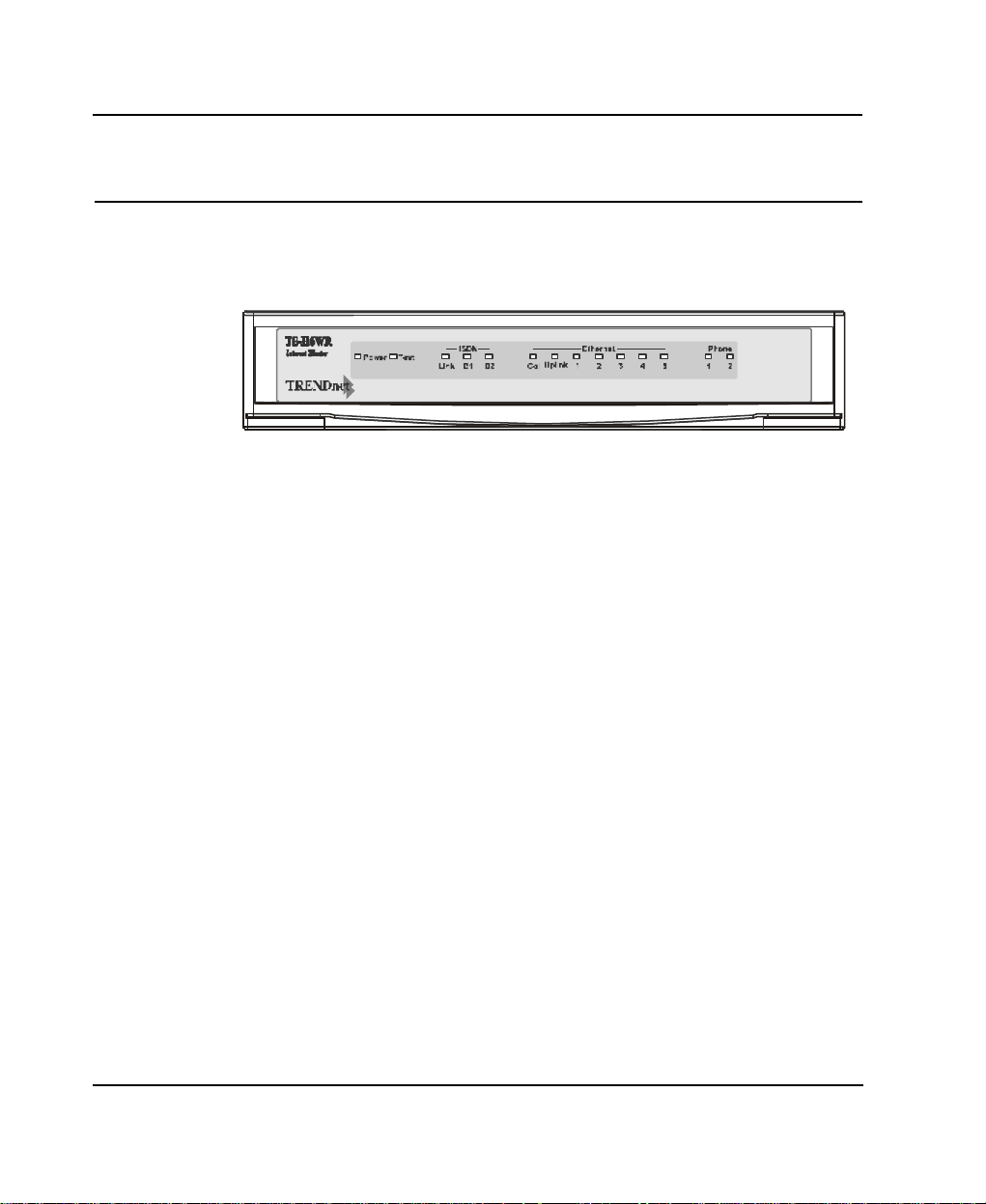
The TW-H6W1IR Front Panel
Names and descriptions of your router’s front panel LEDs are given
below:
POWER— Comes on as soon as you connect the router to the power
adapter and plug the power adapter into a suitable AC outlet.
TEST — Should be blinking if the router is functioning properly.
ISDN – LINK— Indicates that the router has an ISDN line connected
to the ISDN interface and it has been successfully initialized.
ISDN – B1 and B2— On if there is an active ISDN session on that
channel or if that channel is making or receiving a call.
ETHERNET – COL— Shines yellow when a collision occurs on the
LAN, that is, when two devices have attempted to transmit at the same
time.
ETHERNET – Uplink and 1 through 5— Each of these indicators
shines green when a connection to an Ethernet device is detected. The
indicator blinks when a transmission is received from the device, and
shines yellow when the device has been partitioned, that is, temporarily
isolated from the LAN because of excessive collisions (partitioning is a
required capability of all Ethernet hubs).
Installation 11
Page 20
TW -H6W1IR ISDN Remote Router
PHONE – 1— Lights up when standard phone port 1 is in use.
PHONE – 2— Lights up when standard phone port 2 is in use.
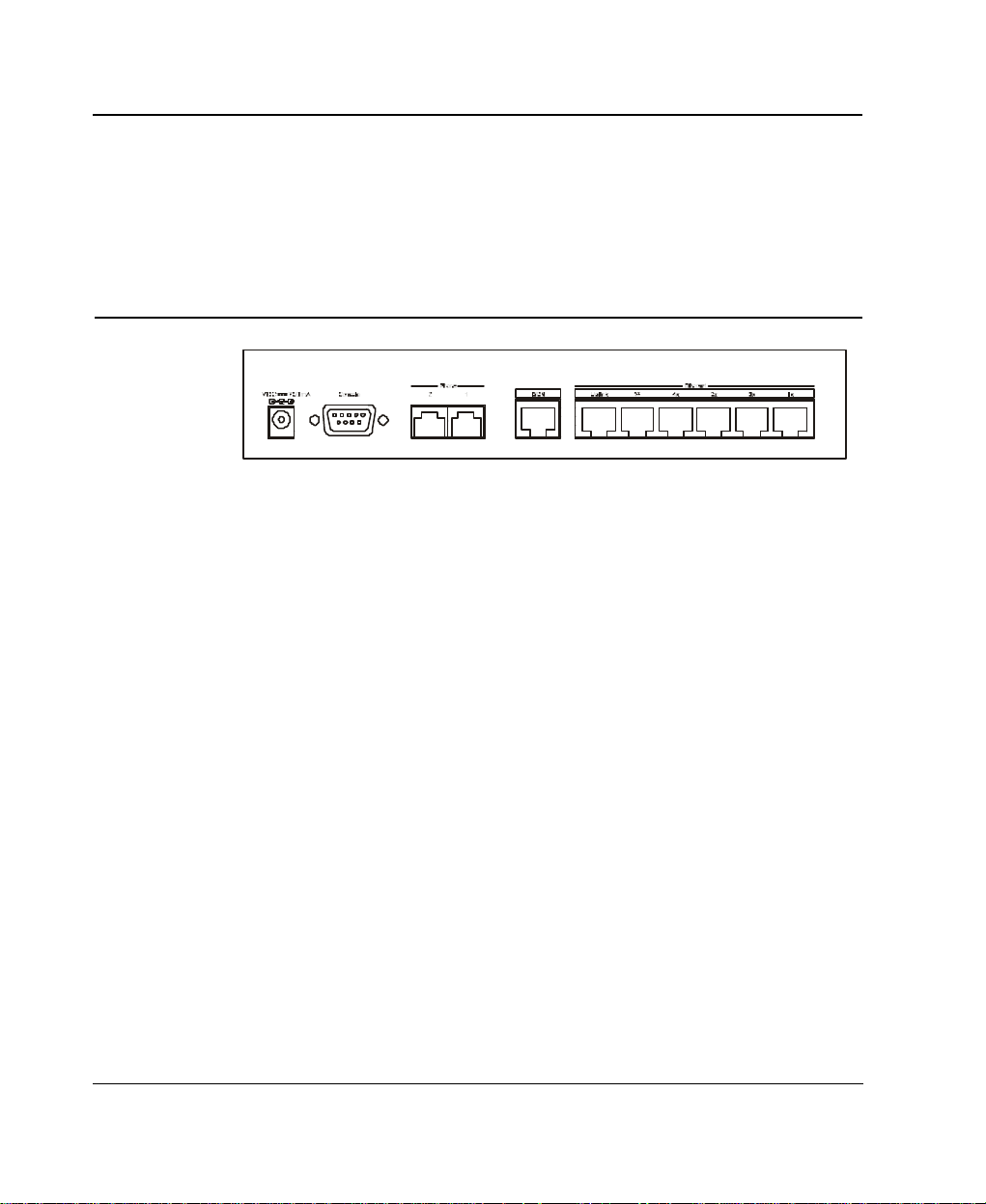
The TW-H6W1IR Rear Panel
POWER — This socket is an 18 volt, 750mA power input jack. If the
power adapter included with the router has been lost or misplaced,
please ensure that the replacement adapter meets both the voltage and
amperage requirements.
CONSOLE – This 9-pin RS-232 port is used for connecting a console
or PC running a terminal emulation program. It provides out-of -band
m anagement capabilities for the initial setup and configuration of the
router.
PHONE 1 and 2 – These normal telephone jacks can be used to
connect telephones or fax machines to the router for use over the ISDN
lines. Plug telephone devices into these jacks as you normally would
into a telephone wall socket.
ISDN – This socket is used to connect the ISDN line to either an NT1 or directly to the ISDN wall jack, depending on the type of service
delivered by your phone company.
ETHERNET – The six Ethernet ports function as a normal 10 Mbps
10BASE -T Ethernet hub.
12 Installation
Page 21

TW -H6W1IR ISDN Remote Router
?? Uplink – This port is used to connect the router to another
hub using a straight-through twisted-pair cable.
?? Ports 1x to 5x – These five ports can be used to connect
end-stations to the router using straight-through cables.
Telephone Features
Up to two telephones can be attached to the TW-H6W1IR router via
the Phone 1 and Phone 2 telephone jacks located on the rear of the
router. The router enables the attached telephones to have a number of
features which may or may not be found on normal telephones and are
described below. Additional features which must actually be configured
are described in the Interface Configuration – ISDN Sub-menu
section of this manual.
? ? Hold – This feature is very similar with and can work in conjunction
with call waiting as defined in the Interface Configuration – ISDN
Sub-menu section of this manual. Press Flash 0 to place someone
on hold (Flash is a very brief hanging up of the phone). Press Flash
2 to take the caller off hold.
? ? Hold (and pick up from another location) - Telephones
connected to the router can be put on hold by pressing Flash 71,
72, 73, or 74. Press the same number to take the caller off hold
and speak from another phone on your telephone network.
? ? Call forwarding – If you wish to forward incoming calls to a
different telephone, press *77* and then the phone number you
wish to forward the call to. All incoming calls will automatically be
Installation 13
Page 22

TW -H6W1IR ISDN Remote Router
forwarded to the phone number entered. Press #77# to cancel call
forwarding.
? ? Three-person conference call – To use this feature, conference
calling must be enabled by the telephone company. After this is
done, pick up a phone and place a call. After connected, press
Flash 0 (refer to call waiting in the Interface Configuration –
ISDN Sub-menu section of this manual) and dial the second
number. After connected, press flash 3 to speak to both parties at
the same time. Press Flash 0 to hang up with the first party called.
Press flash 1 to hang up with the second party called.
? ? Call transfer – To transfer a call to the other phone jack on the
router: if using Phone 1, press flash 20. If using Phone 2, press flash
10.
Installation and Initial Configuration
This section discusses the different connections that can be made to the
router when setting it up.
Initially, you will only wish to connect the console to the router in order
to configure the other ports. Once that is complete, you will need to
turn off the power to the router and plug in the connection cables to the
other devices. Next, power on the other devices. When they have
finished powering up, power on the router. Each of these steps is
described in detail in the sections below. Please skip any setting
adjustments that do not apply to your configuration needs.
14 Installation
Page 23

TW -H6W1IR ISDN Remote Router
For the initial configuration of your TW-H6W1IR, you must use an
RS-232 console connection, either to a computer running serial
communications software or to a serial data terminal.
After the router has been successfully installed and the initial
configuration is complete, you can continue to modify settings through
the console, or you can change configuration settings through a remote
Telnet connection or through a web browser. See the chapters entitled
Configuration and Management and Using Telnet for detailed
instructions on using Telnet to configure your TW-H6W1IR.
A Warning on Connection Cables
ISDN and Ethernet cables are very similar to each other. It is important
that you use the correct cable for each connection; otherwise, your
router could be damaged.
Before connecting or disconnecting an RS-232 cable between two
devices, turn both devices off to avoid any chance of damaging them.
Step 1 - Setting up the Console
The initial setup of the TW-H6W1IR, requires connecting a console
to the 9-pin RS-232 Diagnostic port on the router’s rear panel. A
serial cable is supplied with the router in order to make this
connection. A console can be a terminal, such as a VT-100, or a
normal PC running terminal emulation software (such as Microsoft
HyperTerminal, included with Windows). The terminal emulation
software needs to be configured to the following parameters:
?? VT100 terminal emulation
Installation 15
Page 24

TW -H6W1IR ISDN Remote Router
?? 9600 baud
?? No parity, 8 data bits, 1 start bit, 1 stop bit
?? No flow control
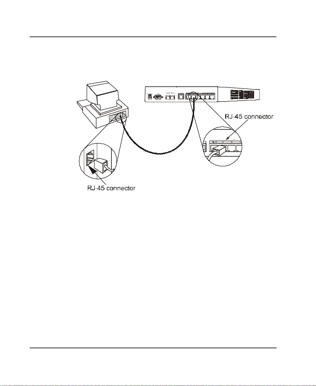
Step 2 - Connecting the Console to the Router
A serial cable is included in the TW-H6W1IR package. To connect
this cable, plug its nine-pin connector into the 9-pin RS-232 Diagnostic
port on the router’s rear panel, then connect the other end to the serial
port on the rear of your computer or data terminal.
Please make sure both machines are turned off before making this
connection.
After the connection is made, first power on the console. If you are
using a PC, run the terminal emulation software at this time. After the
PC and the terminal emulation software are up and running, power on
the router.
Using the Console
The Console Program is the interface that you will be using to
configure your TW-H6W1IR. Several operations that you should be
familiar with before you attempt to modify the configuration of your
router are listed below:
? ?Moving the Cursor. Within a menu, use Tab and arrow keys
to navigate through different information fields.
? ?Moving Forward to Another Menu. To move forward to a
sub-menu below the current one, use Tab or arrow keys to
16 Installation
Page 25

TW -H6W1IR ISDN Remote Router
position the cursor on the sub-menu item and press Enter to
view the selected sub-menu.
? ?Entering Information. There are two types of fields that you
will need to fill in. The first requires you to type in the appropriate
information. The second gives you choices to choose from. In the
second case, press the space bar to cycle through the available
choices. Upon configuring all fields the sub-menu, position the
cursor on SAVE and press Enter to save, or position the cursor
on EXIT to cancel.
? ?Refresh Screen. Console screens are notorious for becoming
garbled. When this happens, simply press <Ctrl> + <R> to
refresh the contents of the screen.
Step 3 - Connecting an ISDN Line to the Router
Your phone company will provide an S/T interface into your home or
office. Plug the ISDN line from the router directly into the ISDN wall
socket provided by your phone company.
Step 4 - Connecting a Telephone or Fax Machine to the Router
You can connect a regular telephone, fax machine, or modem to your
router to be used for analog calls. Note that the router’s other functions
all work the same whether you connect an analog device or not.
To connect an analog device, just plug one end of the device’s cord
into one of the sockets on the back of the router marked PHONE 1 or
PHONE 2.
Installation 17
Page 26

TW -H6W1IR ISDN Remote Router
To have incoming calls directed to a device on a PHONE jack, you
must enter the telephone number for the phone in the console program
under the Interface Configuration, ISDN submenu.
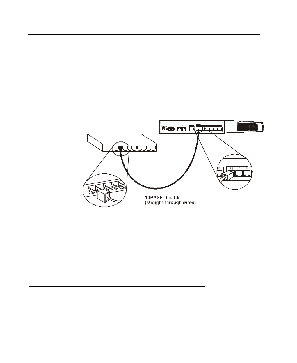
Step 5 - Connecting Ethernet Cables to the Router
Your TW-H6W1IR has six ports for connecting 10BASE-T Ethernet
devices to form a LAN. The jacks for ports 1 through 5 are wired to let
you connect network end nodes (computers, servers, bridges, other
routers, etc.) using standard “straight-through” EIA (Electronic
Industries Association) Category 3 or higher twisted-pair cables. The
jack for the sixth port is labeled Uplink and is wired to let you connect
to another 10Mbps Ethernet or dual-speed hub using a straight-through
cable, or an end node using a cross-wired cable.
Please refer to the following chart when deciding on the type of cable
necessary for a given connection:
DEVICE PORT
USED
Norma
l
Router Server (or PC) Straight-Through (||)
Uplink
Server (or PC) Crossover (X)
18 Installation
DEVICE BEING
CONNECTED
Hub or
Switch
Hub or
Switch
PORT
TYPE
Normal Crossover (X)
Uplink Straight-Through (||)
Normal Straight-Through (||)
Uplink Crossover (X)
CABLE TO USE
Page 27
TW -H6W1IR ISDN Remote Router
The figure below shows how to make an Ethernet connection between
the router and a network end node.
Important Notes on Ethernet Connections
Observe the following rules when connecting devices with twisted-pair
Ethernet cables:
? ?For both end-node and uplink connections, use only EIA
Category 3 or higher-grade twisted-pair data cables with RJ-45
plugs. In almost all cases, only standard straight-through cables
are needed.
? ?Make sure no cable is more than 100 meters (328 feet) long.
? ?When uplinking two hubs together with a straight-through cable,
use an uplink-type jack at one end, and an end-node-type jack
at the other.
Installation 19
Page 28
TW -H6W1IR ISDN Remote Router
? ?If uplinking more than two hubs together, observe the 5-4-3 rule:
no signal, in order to go from one end node to another, must ever
pass through more than five twisted-pair cables, four repeaters
(that is, hubs), and three uplink cables. This is the maximum signal
path in twisted-pair Ethernet. Also be sure never to allow a signal
loop to form.
Note that you can connect an end node through the Uplink jack,
but to do so you must use a cross-wired cable or cable
converter.
Step 6 - Powering Up Devices for Initial Configuration
Plug in the included 18V DC, 750 mA power adapter into the power
jack on the router’s rear panel.
20 Installation
Page 29

TW -H6W1IR ISDN Remote Router
You should have now connected the RS-232 cable to the console, the
ISDN phone line, one or more Ethernet cables, and the power adapter.
At this point in the installation process you can now power up the
console computer, run the terminal emulation software (if necessary),
and then power up the TW-H6W1IR.
Step 7 - Initial Configuration of the Router
After the console is properly connected and both devices are powered
on as described in the preceding sections, you should see the router run
through the power on self test (POST). Finally, it will arrive at the logon
screen shown below. If the login screen does not appear, press <Ctrl>
+ <R> to refresh the screen.
Installation 21
Page 30

TW -H6W1IR ISDN Remote Router
To log on to the router, use the factory set username and password
‘Admin’ (without the quotes). Please note that the user name and
password are case-sensitive.
Upon entering the username and password (using the <tab> key to
jump to the next field), position the cursor on OK and press <Enter>.
You will then see the following Main Menu:
Step 7 - Configuring the LAN Port
Preparing the router for connection to a LAN only requires enabling the
LAN port, enabling IP networking, assigning the LAN port an IP
address and enabling telnet (if necessary). After the LAN port is
configured, all other features on the router can be configured remotely
through the LAN by using the included Windows-based Router
Configuration Utility or Telnet. Regardless, the router can always be
configured using a console connected to the RS-232 Console port.
To configure the LAN:
22 Installation
Page 31

TW -H6W1IR ISDN Remote Router
1. The LAN port must be enabled in the Interface
Configuration sub-menu.
? ?Choose Interface Configuration, LAN.
? ?Position the cursor over the State item and press <space
bar>. The State will change from Disable to Enable.
? ?Position the cursor on the Save option at the bottom of the
screen and press <Enter> to save the new setting.
? ?Choose Exit in the sub-menus to return to the Main Menu.
2. Enable IP Networking
? ? Choose Network Configuration, IP
Configuration.
? ? Position the cursor over the last item IP Networking
and press <space bar> to Enable it.
? ? Position the cursor on the Save option at the bottom of the
screen and press <Enter> to save the new setting.
3. Assign an IP address to the LAN port in the Network
Configuration sub-menu of the Main Menu.
? ?Still in Network Configuration, IP
Configuration submenu from Step 2 above, choose IP
Stack Configuration, LAN.
? ?Enter a valid IP address for the LAN in the first item. You may
also enter a Netmask if you wish. For more information about IP
Installation 23
Page 32

TW -H6W1IR ISDN Remote Router
Addresses and Subnet masks, please refer to Appendix B – IP
Concepts.
? ?Position the cursor on the Save option at the bottom of the
screen and press <Enter> to save the new setting.
? ?Choose Exit in the sub-menus to return to the Main Menu.
4. Enable the Telnet/Discovery function on the router.
? ? From the Main Menu choose Advanced Functions.
? ? Choose the Telnet/Discovery Enable option and
enable telnet.
? ?Position the cursor on the Save option at the bottom of the
screen and press <Enter> to save the new settings.
? ?Choose Exit in the sub-menus to return to the Main Menu.
The router can now be accessed via the LAN by Telnet, the Webbased TW-H6W1IR Router Configuration Utility (included with the
router) and other SNMP management applications.
If you have any questions regarding the settings you made or other
settings in the submenus, please refer to the next chapter
Configuration and Management.
Step 8 – Plugging in All Devices
You can now plug in and power on all other devices connected to the
router. Do not power on the router yet.
24 Installation
Page 33

TW -H6W1IR ISDN Remote Router
The router is now able to use the LAN ports.
The router must be further configured in order to get the built-in ISDN
modem to function properly, to perform other routing functions, and to
manage your IP network. This can now be done by using the console,
the included Web-based Configuration Utility or Telnet.
For more information about configuring or managing the router, please
refer to the next chapter – Configuration and Management.
Installation 25
Page 34

TW -H6W1IR ISDN Remote Router
Configuration and Management
After the initial startup (POST) test, the router will prompt you for login
and password. This is the opening page of the router’s out-of -band
configuration program, called the Console program. The Console
program is stored in the Flash memory chips in the router and the
settings are written in EEPROM chips in the router. It is the most basic
level for configuring and managing the router and the network to which
it is connected.
If you’re starting the router for the first time, the default login and
password is “Admin” – the login and password are case-sensitive,
alphanumeric characters.
26 Configuration and
Management
Page 35

TW -H6W1IR ISDN Remote Router
Note that once you are in the Main Menu, if there is no activity for
more than 5 minutes, the router will automatically log you out. Your
first endeavor should be to increase the ‘timeout’ time by adjusting the
appropriate value in the System Information sub-menu.
The router can also be configured remotely through a LAN or ISDN
connection by using the included Router Configuration Utility or Telnet.
However, if you wish to do this, the console program must first be used
to initially configure the relevant port on the router. Please see Step 7 -
Initial Configuration of the Router on page 21 of this manual for
more detailed information.
Console Program Main Menu
The Main Menu is shown below.
Configuration and Management 27
Page 36

TW -H6W1IR ISDN Remote Router
As mentioned earlier, your first endeavor should be to increase the
automatic timeout. Enter the System Information to do this. You will
see this screen:
System Information
This menu contains administrative and system-related information.
The above parameters are described as follows:
?? System Description – this is a non-changeable, short description
of the product.
?? System Object ID – this is the enterprise-specific MIB Object ID
indicating this type of router.
28 Configuration and
Management
Page 37

TW -H6W1IR ISDN Remote Router
?? System Up Time – shows how long the router has been running
since the last power off or reset.
?? System Contact – enter the name of the department or individual
responsible for maintaining the router.
?? System Name – give the router a descriptive name for
identification purposes.
?? System Location – enter the geographic location of the router.
?? Console/Telnet Display Timeout in Minutes – this is a security
measure to automatically logoff from the console menu after a given
idle time. Enter a timeout time between 0 and 90 minutes. Zero
specifies no timeout.
?? System MAC Address –the physical address of this router.
?? ISDN Switch Type – the type of ISDN switch used by the
telephone company that the TW-H6W1IR can communicate with.
The TW-H6W1IR currently supports only the DSS1 switch type.
Configuration and Management 29
Page 38

TW -H6W1IR ISDN Remote Router
Interface Configuration
Under Interface Configuration in the main menu is the following
interface configuration screen, used to configure the LAN and ISDN
interfaces:
30 Configuration and
Management
Page 39

TW -H6W1IR ISDN Remote Router
LAN Sub-menu
The parameters are described below:
?? Description – this is a user-defined, 32-character identifier used to
name the LAN.
?? Operation Mode – The LAN port is 10BASE-T only.
?? State – this is a toggle, to disable or enable the LAN interface.
Configuration and Management 31
Page 40

TW -H6W1IR ISDN Remote Router
ISDN Sub-menu
The parameters are described below:
?? Description – this is a user-defined, 32-character identifier used to
name the ISDN.
?? Switch Type – this parameter defines the type of ISDN service
used. Currently, the TW-H6W1IR only supports DSS-1 type
ISDN lines.
?? B1 and B2 Channel Usage – this defines whether the ISDN line is
a leased line or a normal switched line. If you are not using a leased
line connection, set this item to Switch.
?? Country ID – this field needs to contain the country parameter.
Without this information, the router cannot establish a connection. A
list of country ID numbers is located in Appendix E – Country ID
Numbers.
32 Configuration and
Management
Page 41

TW -H6W1IR ISDN Remote Router
?? ISDN Data – this field must contain the incoming telephone
number for data calls. In other words, it is your ISDN line’s data
phone number.
?? A/B Adapter 1 and 2 – enter the telephone numbers for your
voice/analog lines.
?? Phone 1 and 2 Call Waiting – If you have applied for and
received call waiting capabilities for your ISDN voice lines, you
must enable these settings in order for the call waiting feature to
function.
There are 4 special operations for using call waiting (flash means a
very brief hanging up of the phone. In other words, for the first
option below, flash 0, click the hang up button on your phone very
quickly and then press the number 0 on your telephone’s keypad):
Flash 0 – disconnect the first phone call established.
Flash 1 – disconnect the second phone call established.
Flash 2 – switch between the two phone calls.
Flash 3 – speak to both parties simultaneously (if conference calling
is enabled by your phone company).
?? POTS Lines – [Plain Old Telephone Service]. Enables or disables
phone calls on the Phone 1 and Phone 2 jacks on the rear of the
router.
?? Global Reception – When this is enabled, the Phone 1 and Phone
2 jacks will receive all phone calls directed to them by the
telephone company’s switch. When disabled, the router will check
incoming calls to the Phone 1 and 2 jacks against the telephone
numbers specified in the A/B Adapter 1 and 2 fields above.
Configuration and Management 33
Page 42

TW -H6W1IR ISDN Remote Router
?? Block Outgoing CLID – When this is enabled, your ISDN data
phone number and voice phone numbers will never be sent out
when trying to establish a connection. Thus, even if sites being
called have Caller ID, they still won’t be able to know your phone
number.
?? Auth[entication] Type – this defines the authorization protocol
that will be used when accepting a dial-in connection. The choices
are Password Authentication Protocol [PAP], Challenge
Handshake Authentication Protocol [CHAP] or None. PAP and
CHAP do not provide a screen for users to manually enter their
Username and Password – instead, this data must be entered into
the dialing software before placing the call. Make sure the device
dialing in is using the same protocol as defined here. The None
setting may be used when you do not wish dial-in users or networks
to identify themselves or be subject to security.
?? Call Bumping – This setting only takes effect when both B
channels are connected and using multi-link PPP. If this is the case
and call bumping is enabled, when you receive and incoming voice
call, the second B channel will be dropped (with all traffic being
moved to the first B channel) and the voice call will be received. If
disabled, both B channels will continue their data transmissions
uninterrupted and the voice call will be ignored.
?? State –enables/disables the ISDN port.
34 Configuration and
Management
Page 43

TW -H6W1IR ISDN Remote Router
Network Configuration
IP protocol configuration and static routes are configured in the
Network Configuration sub-menu. This menu is shown below:
IP Stack Configuration
The network interface IP address, mask and protocols are specified in
the IP Stack Configuration submenus. Below, the submenus for both
the LAN and ISDN interfaces are shown.
Configuration and Management 35
Page 44

TW -H6W1IR ISDN Remote Router
The parameters are described below:
?? IP Address – this is the IP address for the router on the network
to which this interface is connected.
?? Netmask – this is a 32-bit bit mask that shows how the IP address
is to be divided into network, subnet and host parts. The netmask
36 Configuration and
Management
Page 45

TW -H6W1IR ISDN Remote Router
has ones in the bit positions in the 32-bit address which are to be
used for the network and subnet parts, and zeros for the host part.
The mask should contain at least the standard network portion (as
determined by the address's class), and the subnet field should be
contiguous with the network portion.
?? Forwarding (LAN) – this enables or disables communications
between this router and other router(s) on the LAN.
?? State (ISDN) – this is a link method between this interface and
adjacent router(s). The methods are described:
1. AUTO – this obtains and utilizes the IP address assignment
from your ISP (Internet Service Provider).
2. DISABLE – this disables this interface.
3. IP STACK – this enables this interface, and the IP address
used will be the value of the parameter, IP Address.
4. UNNUMBER – this utilizes a method of connecting this router
with adjacent routers, without having to define an IP network
prefix between them. The adjacent routers must have
UNNUMBER capability too.
?? Routing Protocol – this is a distance vector routing protocol. RIP
is an Internet standard Interior Gateway Protocol defined in RFC
1058 and RFC 1723. Routing information is sent periodically
(each 30 seconds, or triggered by topology change) to an adjacent
router. The adjacent router must be using the same protocol.
Setting this to RIPV1&V2 will give the router the ability to make
routing information exchanges with any adjacent router.
Configuration and Management 37
Page 46

TW -H6W1IR ISDN Remote Router
?? Routing Mode – this parameter allows the router to specify the
extent to which it partakes in the RIP on this port. The options are
described below:
1. None – the router will not participate in any RIP
2. Listen – the router will incorporate routing information
3. Talk – the router will send adjacent routers its own
4. Both – the router will incorporate routing information
?? IP Multicasting – this feature enables or disables the router’s
ability to route IP Multicast packets from one interface to another
(for example, from the LAN ports to the ISDN port). IP
Multicasting is a bandwidth-saving method for transmitting data to
more than one host. IP Multicasting is often used when
sending/receiving audio or video data. When IP Multicasting is
enabled, the router will search its multicast forwarding table and
depending on the result of the search will either forward the packet
or add the group to the table.. If IP Multicasting is disabled, all
multicast packets received by the router will be dropped, effectively
limiting multicasting to the LAN. The router can also perform
DVMRP if this feature is enabled (see Multicast Protocol below),
which allows the TW-H6W1IR to share multicast information with
other routers, enabling IP multicasting over the ISDN port.
exchange with adjacent routers.
from adjacent routers, but will not send its own routing
table.
routing table, but will not incorporate routing information
from them.
from adjacent routers, and will send adjacent routers it’s
own routing table.
38 Configuration and
Management
Page 47

TW -H6W1IR ISDN Remote Router
?? Multicast Protocol – if this parameter is set to None, the router
will only use the Internet Group Management Protocol (IGMP), if
IP Multicasting is enabled above. This effectively limits multicast
data to the local network. If set to DVMRP (Distance Vector
Multicast Routing Protocol), the router will also use this protocol to
share its multicast information with other routers (much like RIP), in
effect, enabling multicasting on the WAN (ISDN) port.
?? IGMP Version – configures the router to use either IGMP version
1 or 2. A major difference between the two is that version 2 allows
the router to communicate multicast information with other routers
(via the ISDN port), even if the other router isn’t using DVMRP.
?? DHCP Client (LAN) – this feature allows the LAN port to be
assigned an IP address from a DHCP server other than the one in
the router. This feature should be enabled only for special
configurations (such as the presence of a cable modem on the
LAN) where you wish the router to work with a device on the
network that must act as a DHCP server. Otherwise, this feature
should be kept disabled.
?? RIP Spoofing (ISDN) – this feature should only be enabled if you
have more than one router on your network and this router is
providing your WAN connection. In this case, if the WAN
connection is dropped due to inactivity and this feature is enabled,
RIP packets will be sent to the other routers on the network telling
them that data can still be sent to the WAN via this router.
Otherwise, the other routers will learn that the WAN link has been
disconnected and will no longer forward packets destined for the
WAN to this router, causing the packets to be dropped before
Bandwidth on Demand has a chance to reestablish the WAN
connection.
Configuration and Management 39
Page 48

TW -H6W1IR ISDN Remote Router
IP Static Route
A static route is a permanent entry in the routing table. Static routing
provides a means of explicitly defining the next hop router for a
particular destination network IP address. Each static route entry also
allows for a metric (a.k.a. hop count) to be specified.
The parameters are described below:
?? IP Address – this specifies the destination network IP address (or
a host, depending on the netmask) and pairs it with a gateway.
?? Netmask – this mask shows how the destination IP address is to
be divided into network, subnet and host parts. The netmask has
ones in the bit positions in the 32-bit address which are to be used
for the network and subnet parts, and zeros for the host part.
?? Gateway – this is the adjacent next hop router, for which the
packets, arriving to this router with this destination IP address, will
be forwarded.
40 Configuration and
Management
Page 49

TW -H6W1IR ISDN Remote Router
?? Hops – this is an associated RIP metric that may have its value set
between 1 and 15, inclusive. A metric value higher than 15 (such
as 16) means that the network is unreachable.
?? Intf [Interface] – this is the network interface containing the
gateway that the packets will be forwarded through.
?? State – this enables/disables a particular entry.
IP Static Route Examples
The IP Static Route Table shown in the example IP Static Route screen
above has the first three entries configured for common implementations
of static routing.
The first entry assumes that ISDN1 has a connection to the Internet and
defines the default next hop router. If you use this router to connect to
the Internet it is very important that you create an entry here that defines
the default next hop router as your ISP. This configuration is also
commonly used when RIP exchanges with other Internet routers (on
ISDN1) are disabled.
The second entry shows how to configure static routes when there is
another router on the LAN. The IP Address shown (202.12.125.0) is
the network address for a branch office, for example. The Gateway
Address (210.172.23.1) is the IP address to the LAN port on another
router on the LAN that maintains an ISDN connection to the branch
office.
The third entry is an example of an enterprise ISDN connection
(through telephone lines) to another router, at a branch office for
example. The IP Address is the network address of the branch office.
The Gateway Address is the IP Address of the ISDN port on the
Configuration and Management 41
Page 50

TW -H6W1IR ISDN Remote Router
branch office router. This configuration assumes there is a modem on
ISDN2 maintaining a dial-up connection to the branch office.
IP Networking
Under the IP Configuration sub-menu, the IP Networking function can
toggle to connect/disconnect this router from the entire IP network.
When IP Networking is disabled, all routing functions are stopped. The
only IP Address the router will act on is its own, via Telnet for example.
Router Advertisement
When this option is enabled, the router will periodically send out ICMP
packets that announce itself on the network. These ICMP packets are
utilized by the Windows 98 or later operating system, which will
automatically update the default gateway setting on the computer in
which it is installed.
42 Configuration and
Management
Page 51

TW -H6W1IR ISDN Remote Router
SNMP Agent Configuration
The Simple Network Management Protocol (SNMP), defined in STD
15, RFC 1157, is a protocol governing the management and the
monitoring of IP network devices and their functions. The TWH6W1IR supports the use of SNMP to acknowledge communication
between management stations and itself. Basically, the TW-H6W1IR,
when connected to the network, acts as an SNMP agent, a software
process that responds to queries using SNMP to provide status and
statistics about the router.
Following is a description of how to configure the TW-H6W1IR for
SNMP management.
From the main menu, select SNMP Agent Configuration. This will
bring you to the SNMP Agent Configuration Menu, shown above.
Configuration and Management 43
Page 52

TW -H6W1IR ISDN Remote Router
SNMP Community Configuration
Select and Enter the SNMP Community Configuration sub-men u.
You will see the following configuration screen:
The parameters are described below:
?? SNMP Community String – this community string is a user-
defined identifying name used to group together some arbitrary set
of SNMP application entities managed by the network manager.
?? Access Right – this element of the set {READ ONLY,
READ/WRITE} is called the SNMP access mode. If the SNMP
Community String has an Access Right of READ/WRITE, then that
Community String is available as an operand for the get, set, and
trap operations. Otherwise, if the Community String’s
corresponding Access Right is READ ONLY, then it is available as
an operand for the get and trap operations only.
?? Status – this validates or invalidates the use SNMP Community
String, by setting the string to ‘Valid’ or ‘Invalid’. Note that setting
44 Configuration and
Management
Page 53

TW -H6W1IR ISDN Remote Router
the use of the string to ‘Invalid’ is the same as removing the string,
however, the string remains so as to be validated at an appropriate
time.
SNMP Trap Manager
From the SNMP Agent Configuration menu, select and enter the
SNMP Trap Manager sub-menu. You will see the following
configuration screen:
The parameters are described below:
?? IP Address – enter the IP address of the host who will act as an
SNMP Management Station. The TW-H6W1IR router will send
SNMP traps to these addresses.
?? SNMP Community String – the community string is a user-
defined identifying name used to group together some arbitrary set
of SNMP application entities managed by the network manager.
Traps will be sent to the IP Address (previous parameter) as long
Configuration and Management 45
Page 54

TW -H6W1IR ISDN Remote Router
as the corresponding Community String, in the Management
Station’s trap manager software, is the same.
?? State – this validates or invalidates the use of the SNMP
Community String, by setting the use of the string to Valid or
Invalid. Note that setting the string to Invalid is the same as
removing the string, however, the string remains so as to be
validated again at an appropriate time.
SNMP Authenticated Trap
Returning to the SNMP Agent Configuration menu, you can ‘Enable’
or ‘Disable’ an authentication failure trap message being sent to the
Management Station by the router. When an SNMP packet with an
invalid community name is received, it will be dropped. If this parameter
is enabled, a trap will be sent to the network manager; if this parameter
is disabled, no trap will be sent.
46 Configuration and
Management
Page 55

TW -H6W1IR ISDN Remote Router
Advanced Functions
The Advanced Functions menu contains most of the more complex
configuration settings and is shown below:
Remote Access Configuration
The Remote Access Configuration menu is used to set up the router for
dial -in and dial-out connections over the ISDN line. An ISDN line has
a D channel for establishing connections and two B (Bearer) channels,
which transmit and receive the actual signals, whether voice or data.
The two B channels can support two independent remote connections
or be banded together using Multi-link PPP to implement Bandwidth on
Demand (configured separately in the PPP Configuration menu, the
last item in the Advanced Functions window).
The B-Channels can also carry voice and fax calls, which are routed to
the telephone jacks located on the rear of the router. Please note,
Configuration and Management 47
Page 56

TW -H6W1IR ISDN Remote Router
however, that the TW-H6W1IR can maintain only two connections at a
time via the two B channels, whether the connections are voice, data,
dial -in users, remote networks or a combination thereof.
Remote Operation Overview
The TW-H6W1IR is very flexible and can be configured for a variety
of remote connections. Since configuring the router can be quite
complex - depending on the number and type of remote connection(s)
you wish to implement – we have described some of the basic functions
and procedures below.
Dial-In User Connections
Dial -in users are defined as a single user on a computer, such as a
person working at home, who dials into the office to use network
resources. In almost all cases, a Dial-In User Profile needs to be set up
for each user who will dial in to the router so the router can tailor the
connection for each user. Once this is done, the remote user will be
able to use network resources as if he were connected locally. When
the user dials into the TW-H6W1IR, the call comes into the D-channel
and after answering the phone, the TW-H6W1IR:
1. Identifies the Username and Password using the authentication protocol
defined in the Interface Configuration, ISDN submenu. The dial -in user is
not prompted for this information, but must enter it into his dialing software
before dialing.
2. Checks the Username and Password against those defined in the Dial -In
User Profiles and Remote Network Profiles.
48 Configuration and
Management
Page 57

TW -H6W1IR ISDN Remote Router
3. Assuming a matching Dial-In User Profile is found, the router may
configure the IP address of the remote station (as defined in the Dial-In
User Profile).
4. Configures a dial -in Interface (a virtual circuit) to handle the connection.
5. Establishes the connection on whichever B-channel (physical port) is open
by mapping the dial -in interface to that port.
6. In the case where the Dial -In User does not need to supply a Username and
Password (Auth Type is set to None in the Interface Configuration
submenu) the remote computer must have its own IP address.
Remote Network Connections
Remote networks are defined as other networks (LANs) that have
WAN connections using a router, Internet server, network modem or
similar device (in this document however, we will assume the remote
device is a router). In almost all cases, a Remote Network Profile
needs to be set up for each network that will connect to the TWH6W1IR via the ISDN lines. The Remote Network Profiles are
necessary for the router to identify and tailor the connection to the
remote network’s router. Once this is done, a connection between the
two routers can be made and computers on each network can
communicate with each other.
Dial-In Network Connections
A dial-in network connection is very similar to a dial-in user connection.
When the remote router dials into the TW-H6W1IR, the call comes
into the D-channel and after answering the phone, the TW-H6W1IR:
1. Identifies the Username and Password using the authentication protocol
defined in the Interface Configuration, ISDN submenu.
2. Checks the Username and Password against those defined in the Dial -In
User Profiles and Remote Network Profiles.
Configuration and Management 49
Page 58

TW -H6W1IR ISDN Remote Router
3. Assuming a matching Remote Network Profile is found, the router may
configure the IP address of the remote station (as defined in the Remote
Network Profile).
4. Configures the specified ISDN Interface (a virtual circuit) using the
configuration parameters defined in the Interface Configuration menu and
the Remote Network Profile to handle the connection.
5. Establishes the connection on whichever B-channel (physical port) is open
by mapping the dial -in interface to that port.
Dial-Out Network Connections
Dial -out network connections are much different than dial-in
connections.
When a packet on the LAN reaches the router, the TW-H6W1IR will:
1. Check its routing table to try to identify where this packet should go. It
looks for two variables in the routing table, Gateway address and Interface.
There are four possible results:
I. In the case where the destination resides in the same IP network on the
LAN, the routing engine never acts on the packet and it is sent directly
to the destination through the built-in hub.
II. In the case where the destination resides on a different IP network on
the LAN (which can happen when Multiple Home Configuration is set
up), the router will send out an ARP request to obtain the MAC address
of the destination computer (or router) and deliver the packet. Note that
defining Static ARPs can speed up delivery since the router won’t need
to send out an ARP request.
III. In the case where the router finds a match in the routing table (which
includes IP Static Routes), it uses the Gateway address and Interface
numbers to identify the correct Remote Network Profile to use to dial
out. From the Remote Network Profile, the router gets the telephone
number and other information and dials out, establishes a connection
and delivers the packet. If you have a connection to the Internet, it is
very important that you define the default next hop router in the IP
Static Routes submenu of the console program as your ISP (see the IP
Static Routes section of this manual for more detailed configuration
50 Configuration and
Management
Page 59

TW -H6W1IR ISDN Remote Router
information). This is because if a user on your LAN makes a request to
download a web page for the first time, for instance, since it is the first
time, the TW-H6W1IR will not have any record of the web page’s IP
address. If no default next hop router is defined, the request will be
dropped and the user will get a ‘Destination Unreachable’ error
message. However, if a default next hop router is defined in the IP
Static Routes, the TW-H6W1IR will pass this request on to the ISP (the
request will go through) and the user will receive the web page.
IV. In the case where there is no match for the destination IP address in the
routing table, and no default next hop router is defined, the packet will
be dropped and no action will be taken.
The Remote Access Configuration submenu is shown below. All items
in the submenu are described as follows.
Dial Configuration
You can configure the two ISDN interfaces on your TW-H6W1IR to
dial -out only when a packet is forwarded to that interface, and hang up
after all data has been transferred and the link is idle. This can be used
to lower the cost of an unpopular link or used as a backup link to your
Configuration and Management 51
Page 60

TW -H6W1IR ISDN Remote Router
ISP. This feature is commonly called “Dial on Demand”. ISDN
interfaces can also be configured here to receive calls from dial in users
and other networks, called “Remote Access”. Please note however,
that in all cases, after configuring the ISDN Links in the Dial
Configuration submenu, they must be further configured in the
Dial-In User Profile submenu or Remote Network
Profile submenu.
Dial In IP Pool
The dial in IP pool allows you to define a range of IP addresses that will
be reserved for and assigned to dial-in users.
52 Configuration and
Management
Page 61

TW -H6W1IR ISDN Remote Router
The items are described as follows:
? ? IP Address – is the first IP Address that will be assigned to a dial-
in user.
? ? Range – is the number of IP Addresses that can be assigned. In
the window shown above, dial-in users will be assigned the IP
Addresses 170.100.200.1 or 170.100.200.2 (only two are
necessary since the router used in the examples has only two ISDN
ports).
ISDN Link 1
This submenu contains a number of settings (shown below) which allow
you to configure the router to dial out.
Configuration and Management 53
Page 62

TW -H6W1IR ISDN Remote Router
The parameters are described below:
?? Idle Time – this is the elapsed time (in seconds), of inactivity, that
will trigger the router to disconnect this interface.
?? Dial-Out Retry Time – this is the time (in seconds) the router will
wait before the next dial attempt.
?? Dial-Out Retry Count – this is the specified maximum number of
dial attempts the router will make when trying to establish a
connection on this interface.
?? Dial on Demand – this disables or enables dial on demand on this
interface. If enabled, when a packet arrives at this port, the router
will search for a Remote Network Profile that further configures
this ISDN port for dialing-out.
?? Set Peer IP as Default Gateway – when enabled, this feature
sets the IP address of the remote device as the default gateway
(default next hop router) for all packets not found in the routing
table. This option should be enabled for the ISDN circuit (ISDN1
54 Configuration and
Management
Page 63

TW -H6W1IR ISDN Remote Router
or ISDN2) that is used to connect to the Internet. Also, if the Peer
IP is set as the default gateway here, you still need to define a static
default route in the Network Configuration, IP Static Route
submenu, but you don’t need to designate a gateway IP address for
the static route (the routers will automatically negotiate and adjust
the gateway IP setting accordingly). And also make sure that the
Remote IP Address in the Remote Networks Profile is set to
0.0.0.0. Note that only one ISDN circuit should be connected to
the Internet, and only one ISDN circuit (the same one) should be
the default gateway.
Dial-In User Profile
The Dial-In User Profile is used to configure the TW-H6W1IR for
single users (for example a person working at home) to dial in to the
router and gain access to the network. At least one User Profile must
be configured for each user who will dial in (in conjunction with Dial
Configuration settings). Please note that WAN connections to
computers on other networks must be defined in the Remote Network
Profile submenu.
Up to eight users can be set up to dial in to the router. However, more
dial -in users can be accommodated by using a Radius server as
described in the Radius Configuration section of this manual. Please
note that when a Radius server is being used, the Dial-in User Profiles
will be disabled.
The Dial-In User Profile submenu appears below:
Configuration and Management 55
Page 64

TW -H6W1IR ISDN Remote Router
The parameters in the above window are described as follows:
?? Name – the maximum length is 64 characters. This username is for
password challenges (authentication). The user dialing in must
supply this username in order to be allowed access to the router.
?? Password – this is the password associated with the above Name
field.
?? Rem CLID – Remote Caller ID. This is the telephone number of
the Remote User and is used for security. When a phone number is
entered in this field, the router will make sure that the incoming call
is coming from the same phone number as the one defined here. In
other words, the remote user can only be calling from the telephone
number defined here, otherwise the call will not be accepted. This
function is disabled if the field is left blank.
?? Default IP – this is the IP address that will be assigned to the dial-
in user when the IP Address Supply setting below is set to Default.
56 Configuration and
Management
Page 65

TW -H6W1IR ISDN Remote Router
Assigning an IP address to the remote computer ensures that the IP
address does not clash with other IP addresses on your network.
?? IP Address Supply – this field defines how the remote user will
obtain an IP address. The choices include:
Default – uses the Default IP address defined above,
Dynamic - taken from the Dial In IP pool, or
None - the remote user supplies his own IP Address.
?? State – enables/disables this User Profile.
Remote Network Profile
The Remote Network Profile is used to configure the router for ISDN
connections to other networks. In practice, the TW-H6W1IR will
either dial-out to or receive incoming calls from another router, the
‘gateway’ to the other network.
Configuration and Management 57
Page 66

TW -H6W1IR ISDN Remote Router
?? Remote Name – Name for the remote network that the TW-
H6W1IR is being set up to connect with.
?? Direction – dial-[In], dial-[Out], or [Both]. This field defines
whether the router on the other network will dial-[In] to the TW-
H6W1IR to establish a connection, the TW-H6W1IR will dial[Out] to the other network, or a connection can be established
[Both] ways.
When this is set to In, the TW-H6W1IR will only establish a
connection with the other network by receiving calls on the ISDN
port specified in the Interface field below. Also, the incoming calls
will be subject to the Name, Password and Rem CLID fields in the
Incoming section below.
When this is set to Out, the router will only make calls on the ISDN
interface specified in the Interface field below. Also, the outgoing
calls will be subject to the Name, Password and Phone Number
fields in the Outgoing section below.
When set to Both, the dial in and dial out conditions described
above will both be observed.
?? Interface – ISDN Link 1 [ISDN L1] or ISDN Link 2 [ISDN L2].
This field is used to assign a remote network to a logical (virtual)
interface called a virtual circuit. More than one remote network can
be configured to use the same interface, but they cannot be
connected at the same time. Thus, if you wish to have two WAN
connections operate simultaneously, make sure they are configured
on different interfaces. On the other hand, if you have two dial-out
remote network profiles but wish to keep one line always open for
dial -in users, make sure the two dial-out profiles use the same
interface. In this case, the two profiles will share the same interface;
58 Configuration and
Management
Page 67

TW -H6W1IR ISDN Remote Router
the second one using it after the first one’s idle time has expired and
it has relinquished it.
?? Incoming
?? Name – the maximum length is 64 characters. This username is
for password challenges (authentication). The user dialing in
must supply this username in order to be allowed access to the
router.
?? Password – this is the password associated with the above
Name field.
?? Rem CLID – Remote Caller ID. This is the telephone number
of the Remote User and is used for security. When a phone
number is entered in this field, the router will make sure that the
incoming call is coming from the same phone number as the one
defined here. In other words, the remote user can only be
calling from the telephone number defined here, otherwise the
call will not be accepted. This function is disabled if the field is
left blank.
?? Outgoing
?? Name – the maximum length is 64 characters. Spaces and
punctuation are not usually accepted. This username is for
password challenges (authentication) which are automatically
handled by the router when dialing out. The TW-H6W1IR will
use PAP and CHAP (whichever works) to make the
connection.
?? Password – this is the password associated with the above
Name field.
?? Phone Number – this is the telephone number that will be
dialed to make the outgoing connection.
Configuration and Management 59
Page 68

TW -H6W1IR ISDN Remote Router
?? Remote IP Address – this is the IP address that will be assigned
to the dial-in network when the IP Address Supply setting below is
set to Default. Assigning an IP address to the router dialing in
ensures that the IP address does not clash with other IP addresses
on your network. For dial out connections utilizing dial on demand,
the IP address of the remote router needs to be entered here so the
router knows which remote network to establish a connection with
to deliver the packet.
?? IP Address Supply – this field defines how the router will assign
an IP address to a device dialing in. The choices include:
Default – uses the Remote IP address defined above,
Dynamic - taken from the Dial In IP pool, or
None - the remote user supplies his own IP Address.
?? State – enables/disables this Remote Network Profile
60 Configuration and
Management
Page 69

TW -H6W1IR ISDN Remote Router
DHCP Configuration
The TW-H6W1IR Router implements the Dynamic Host Configuration
Protocol (DHCP), which allows the entire IP network to be centrally
managed by the router. It does this by assigning IP addresses and
configuration parameters to hosts as they are powered on and come
onto the network. This can be a great help for network administration
since many administrative tasks such as keeping track of each
computer’s IP address are handled by the router. The TW-H6W1IR
can implement DHCP in one of the two ways shown below:
DHCP Server Configuration
When acting as a DHCP server, the TW-H6W1IR will manage many
of the IP network parameters. The TW-H6W1IR will never assign a
broadcast or network IP addresses to hosts, even if such an address is
included in the specified range.
Configuration and Management 61
Page 70

TW -H6W1IR ISDN Remote Router
Dynamic IP Pool
The dynamic IP pool screen shown below contains the parameters that
the router can set on the hosts. Please note that the Dynamic IP Pool
cannot be enabled when the DHCP Agent feature is enabled.
The parameters are described below:
?? IP Address – this is the base (starting) address for the IP pool of
IP addresses to be assigned.
?? Range – this is the range of contiguous, IP addresses, above the
base IP Address above. In the above example, the IP addresses
assigned host computers as they come onto the network would be
202.93.47.1, 202.93.47.2 … 202.93.47.100.
?? Netmask – this mask informs the client, how the destination IP
address is to be divided into network, subnet and host parts. The
netmask has ones in the bit positions in the 32-bit address which
62 Configuration and
Management
Page 71

TW -H6W1IR ISDN Remote Router
are to be used for the network and subnet parts, and zeros for the
host part.
?? Gateway – this specifies the Gateway IP Address that will be
assigned to and used by the DHCP clients.
?? Lease Time – this specifies the number of hours a client can lease
an IP address, from the dynamically allocated IP pool. The
maximum value is 65535 and a value of 0 means the lease is
permanent.
?? DNS IP – this specifies the Domain Name System server, used by
the DHCP clients using leased IP addresses, to translate hostnames
into IP addresses or vice-versa.
?? WINS IP – this specifies the IP address of the Windows Internet
Naming Service server. This server has software that resolves
NetBIOS names to IP addresses.
?? Domain Name – this is the common suffix, shared by networked
hosts, used to represent a common network domain.
?? State – this enables/disables the dynamic IP Pool function.
Static IP Pool
The Static IP Pool configuration functions in much the same way as the
Dynamic IP Pool configuration. The only difference is that a particular
IP address can be assigned to a particular host. This is used for hosts
such as servers that need to have static IP addresses to function
properly or to make them accessible to remote users. The host is
identified by the MAC address of its NIC, which must be entered on
this screen.
Configuration and Management 63
Page 72

TW -H6W1IR ISDN Remote Router
The parameters are described below:
?? IP Address – this is the static IP address to be assigned.
?? MAC Address – this specifies the physical address of the
particular host that will receive the above IP address.
All other parameters (Netmask, Gateway, DNS IP, WINS IP,
State, & Domain Name) are identical to those in the Dynamic IP
Pool configuration, in the previous section.
DHCP Relay Agent
The DHCP Relay Agent feature allows the TW-H6W1IR to act as a
go-between for a remote DHCP server assigning IP addresses to local
clients. This can be useful if you wish to have all IP addresses in your
company, including those in branch offices, assigned from a DHCP
server centrally located at your headquarters, for example.
64 Configuration and
Management
Page 73

TW -H6W1IR ISDN Remote Router
Items are described as follows:
?? DHCP Server IP Address – this is the IP address of the remote
DHCP server. When a local computer powers up and sends a
DHCP request for an IP address, the TW-H6W1IR will forward
the request to the address specified here.
?? Time Threshold – this specifies the maximum amount of time (in
seconds) since the host began requesting an IP address. If the value
define here is exceeded, the relay agent will not pass along the
request from the host.
?? State – enables/disables the DHCP Relay Agent function.
Filter Configuration
Your TW-H6W1IR uses filters (configurable at two layers) to screen
packet data, and apply a routing decision. There are two methods for
configuring filters: you can configure a filter at the network layer (IP
filter) to restrict access between networks and reduce unnecessary
Configuration and Management 65
Page 74

TW -H6W1IR ISDN Remote Router
internetwork traffic; and you can configure a filter at the data-link layer
(a general filter) to provide a protocol independent filter.
Good knowledge of network protocols is required to configure a
specific filter appropriately. It is important for the router to operate
correctly, therefore, necessary packets must be allowed to pass through
the filters. In other words, do not attempt to configure filters on a
utilized router unless you understand what you are doing.
The following section describes how to configure the router filter
parameters.
Configuring a Filter Set
Under the Advanced Functions menu, select and enter Filter
Configuration. You will see the following screen:
The three sub-menus are described as follows:
66 Configuration and
Management
Page 75

TW -H6W1IR ISDN Remote Router
? ? Filter State of Interface – this is used to choose the default,
routing decisions for packets, not meeting the criteria for specific
filters.
? ? Layer 2 Filter – this is a data-link layer (protocol independent)
filter. Foreknowledge of the specific protocol, used on the interface
(LAN or WANs), is needed to make effective use of this filter.
? ? IP Filter – this is an IP protocol specific filter, allowing you to,
among other things, prohibit specific packets from entering the
LAN. Alternatively, you can set up filters that allow certain types of
IP packets to enter the LAN.
Filter State of Interface
The Filter State of Interface sub-menu lets you toggle default, routing
decisions, if the packets are not subjected to a filter, routing decision.
In other words, a packet, having not met the criteria for a specific filter
that was applied to a specific interface, will be subjected to this default,
routing decision.
Configuration and Management 67
Page 76

TW -H6W1IR ISDN Remote Router
Each decision on handling packets is described below:
1. Disable – will not apply a filter.
2. Forward – this allows the routing of a packet, even though it
has not met the criteria of the corresponding filter.
3. Drop – this drops (doesn’t allow routing for) a packet that has
not met the criteria for the corresponding filter.
Layer 2 Filter
The Layer 2 Filter sub-menu contains a protocol independent (datalink layer) filter. Foreknowledge of the specific protocol used on the
interface (LAN or WANs) is needed to make effective use of this filter.
The parameters of a filter are described below:
?? Name – this is a 12 character (maximum), alphanumeric, user-
defined name, used to identify the filter.
68 Configuration and
Management
Page 77

TW -H6W1IR ISDN Remote Router
?? Direction – this defines the direction of the frame relative to the
Interface parameter below.
?? State – this is used to choose the routing decision applied to the
frame. The three decisions are described:
1. forward – this allows the routing of the frame, if it has met the
criteria of the corresponding filter.
2. drop – this drops (doesn’t allow routing for) a specific frame
that has met the criteria of the corresponding filter.
3. disable – this does not apply the protocol independent filter.
?? Interface – this applies the filter to a specific interface, either LAN
or one of the ISDN interfaces.
?? Offset – this defines the reference byte for the Length parameter
(described below). The Offset is the number of bytes (octets) from
the beginning of the first byte of the frame header, immediately after
the preamble. The range of the offset parameter is from 0 to 255
octets. The first byte in a packet has an offset 0.
?? Length – this is the number of bytes (octets) from 0 to 8 to
compare from the offset value (the Offset reference byte).
?? Value – this is a 16 digit, hexadecimal field, defining the actual bit
values used to compare with the frame data, at the specified
(Offset) position.
?? Mask – this is a 16 digit, hexadecimal bit mask, used as an
operand in the bit-wise AND operation that will be applied to the
Value parameter.
Configuration and Management 69
Page 78

TW -H6W1IR ISDN Remote Router
IP Filter
The IP Filter is specifically an IP protocols filter, allowing you to,
among other things, firewall your network, prohibiting specific packets
from entering or going out from your network. It is necessary to have
good knowledge of IP protocol before effectively configuring this filter.
The IP Filter parameters are described below:
?? Name – this is a 12 character (maximum), alphanumeric, user-
defined name, used to identify the filter.
?? Direction – this defines the direction of the packet relative to the
Interface parameter below.
?? State – this is used to define the routing decision applied to the
packet. The three routing decisions are described:
1. forward – this allows the routing of the packet, if it has met the
criteria of the corresponding filter.
70 Configuration and
Management
Page 79

TW -H6W1IR ISDN Remote Router
2. drop – this drops (doesn’t allow routing for) a specific packet
that has met the criteria of the corresponding filter.
3. disable – this does not apply the IP filter.
?? Interface – this applies the filter to a specific interface, LAN or
one of the ISDN interfaces.
?? Protocol Type – this is a protocol identifier, as assigned by the
Internet Assigned Numbers Authority (IANA). The values of this
identifier are described in RFC-1700. This router supports the
following:
4. protocol type = 1, this is Internet Control Message (ICMP),
defined in RFC 792.
5. protocol type = 6, this is Transmission Control (TCP), defined
in RFC 793.
6. protocol type = 17, this is User Datagram (UDP), defined in
RFC 798.
?? Src IP – this is the source address in the IP header of this packet.
?? Src Netmask – this mask is bit-wise AND’d with the source IP
address and bit-wise AND’d with the IP address of the incoming
interface. The two results are then compared.
?? Dst IP – this is the destination address in the IP header of the
packet.
?? Dst Netmask – this mask is bit-wise AND’d with the destination
IP address and bit-wise AND’d with the IP address of the
incoming interface. The two results are then compared.
?? Dst Port – this is the destination port, in the TCP or UDP header,
of the packet.
Configuration and Management 71
Page 80

TW -H6W1IR ISDN Remote Router
?? Operation – this comparison operation is applied to the destination
port (the Dst Port parameter) value, of the TCP or UDP header.
?? ICMP Type – this is the type field, in the ICMP header, used to
identify a particular ICMP message.
?? ICMP Code – this is the code field, in the ICMP header, used to
further specify the ICMP type.
?? TCP Flag – this is a hex number, representing the six flag bits in the
TCP header. The value range is from 0 to 3F.
Multiple Home Configuration
Besides the IP address assigned to the LAN interface in the Network
Configuration menu, the LAN may have up to 3 additional IP
interfaces. These additional IP interfaces are referred to as MIP1 to
MIP3. This type of configuration is known as a multiple home
configuration.
Multiple Home can be demonstrated by this example:
72 Configuration and
Management
Page 81

TW -H6W1IR ISDN Remote Router
A company has 625 users (computers) all connected to one physical
network using Ethernet. However, the company only has one Class C
IP network address, 202.100.160.0. This network address will only
support 254 users. To solve the shortage of IP address problem and to
plan for future growth, the company applies for and receives two more
Class C IP network addresses, 203.101.161.0 and 204.102.162.0.
This gives the company a total of 254 x 3 = 762 IP Addresses, which it
assigns to the computer users, with a few left over for future needs. Due
to the nature of IP networks, however, the users in one IP network
domain (202.100.160.0, for example) cannot communicate with users
on a different IP domain (203.101.161.0). Multiple home solves this
problem. When you register the additional IP network addresses in the
Multiple Home Configuration menu on the router, the router will route
data between the three IP networks using the single LAN.
In this router, multiple home configurations only apply to the LAN
interface.
The parameters are described below:
Configuration and Management 73
Page 82

TW -H6W1IR ISDN Remote Router
?? IP Address – this is a network IP address of a separate IP
network on the LAN.
?? Routing Protocol – this is the same as in the Network
Configuration section. Keep in mind that these exchanges are
made with adjacent routers on the LAN, if present.
?? IP Multicasting – this enables/disables IP multicasting on the IP
network you are defining.
All other parameters (Netmask, Routing Mode, Multicast Protocol
and IGMP Version) are identical to those in the Network
Configuration, IP Stack Configuration, ISDN section.
Static ARP
This special function is intended to speed up the process of finding a
host's Ethernet (MAC) address from its network address, and provides
a special condition – any other host acting as an impostor by using the
same IP address as the legitimate host, will be ignored by this router.
Basically, when a packet comes into the router from the ISDN line and
is destined for a host on the LAN, the router will use information
defined here to immediately send the packet to the host rather than send
out an ARP request to find the host’s MAC address.
74 Configuration and
Management
Page 83

TW -H6W1IR ISDN Remote Router
The parameters are described as follows:
?? IP Address – this is the IP address of the host you wish to define a
static ARP for.
?? MAC Address – this is the physical address of the host that is the
authorized owner of the IP address.
?? State – this toggles enable, disable.
Configuration and Management 75
Page 84

TW -H6W1IR ISDN Remote Router
NAT Configuration
Network Address Translation (NAT) is a routing protocol that allows
your network to become a private network that is isolated from, yet
connected to the Internet. It does this by changing the IP address of
packets from a global IP address usable on the Internet to a local IP
address usable on your private network (but not on the Internet) and
vice-versa.
NAT has two major benefits. First, NAT allows many users to access
the Internet using a small number or even a single global IP address.
This can greatly reduce the costs associated with Internet access and
also helps alleviate the current shortage of Internet IP addresses.
Secondly, the NAT process provides some security found in a firewall,
hiding your local network from Internet users, providing a degree of
security to your Internet connection.
To be successfully implemented, NAT should be used only when the
majority of network traffic remains on the local network. In cases
where a large percentage of network traffic is destined for the Internet,
NAT can adversely affect the speed and performance of your Internet
connection. Also, your network servers such as ftp servers, web
servers or mail servers will probably need to be assigned static NAT
IP addresses so their IP addresses remain consistent. This issue will be
further discussed later.
Network Address Port Translation (NAPT) is a subset of NAT where
many local IP addresses and their TCP/UDP port numbers are
translated to a single global IP address and it’s TCP/UDP port number.
In this document, the term NAT will refer to both NAT and NAPT
unless otherwise stated.
76 Configuration and
Management
Page 85

TW -H6W1IR ISDN Remote Router
NAT can work in conjunction with DHCP. Thus, if both are enabled
and properly configured, the DHCP server in the TW-H6W1IR will
assign local IP addresses to computers on your network.
How NAT Works
In the most common NAT configuration, your network uses local IP
addresses that are not valid on the Internet. Internet (global) IP
addresses are unique, with no two devices have the same IP address.
The local IP addresses can be freely assigned to computers on your
network by your network administrator (within guidelines defined later
in this chapter and in Appendix B, IP Concepts). This can be done
manually or by using DHCP. The ISDN port on the router is assigned a
globally unique IP Address that is valid on the Internet, since it will be
sending and receiving data directly to the Internet and is therefore part
of it. Please study the example diagram below carefully.
Configuration and Management 77
Page 86

TW -H6W1IR ISDN Remote Router
Singl
e
Router
IP Address
176.220.22.1
ISDN
Port
NAT
Translator
LAN
Port
192.168.100.1
Global
Local IP
W AN
LAN
192.168.100.2
192.168.100.3
192.168.100.4
192.168.100.5
Please note that in the above diagram, the Gateway IP address settings
for the local PC’s needs to be set to 192.168.100.1, the LAN IP
address of the router.
NAT manipulates the IP addresses in packet headers on a one-to-one
basis. An outgoing data packet (a packet originating from a computer
on the local LAN and destined for a computer outside the private
network) will have its IP address translated as shown below.
78 Configuration and
Management
Page 87

TW -H6W1IR ISDN Remote Router
In the Outgoing Data Packet above, the Source IP address is the IP
address that is translated by NAT. The Destination IP Address is the
IP address of a computer outside the private network, on the Internet
for example. And the Data portion of the packet is the information
payload borne by the packet, for instance a request to view a web
page.
The router logs the changes made to the IP header in its NAT table.
The NAT table enables the router to send replies back to the local
computer as shown below.
In the Inbound Data Packet above, the Destination IP Address is the
IP address that is translated by NAT. The Source IP Address is the IP
address of a computer outside the private network. And the Data
portion of the packet is the information payload borne by the packet,
for example, the contents of a web page.
The actual information in the NAT table depends whether the router is
implementing NAT or NAPT.
It is also of interest to note that this translation process provides a level
of security to your network found in a firewall. If you examine the
outbound and inbound packets above closely, you can see that the
computer outside of the network that is receiving the packet and
sending the response only knows about the global IP address used by
the router, and actually sends the response to that address. The outside
Configuration and Management 79
Page 88

TW -H6W1IR ISDN Remote Router
computer has no knowledge of the internal local network. In fact, the
local network is invisible to all computers outside of it, all information
about it being stored in the router’s NAT table. And this NAT table can
only be affected by computers from inside the local network. The router
will only add new entries or mappings to the NAT table when it
translates addresses on outbound packets. Thus, all traffic must
originate from inside the local network. If the router receives a packet
from the outside (from an intruder attempting to gain access to your
network, for example), the router will examine the source address of
the packet and look for a match in the NAT table in it’s attempt to
deliver it to the correct local computer. Since no entry for this address
exists in the NAT table, the router will drop this packet, denying the
potential intruder of any access.
If you wish, however, to give access to one of your computers to
people on the Internet (your company’s web server, for example), then
you must use a static NAT or NAPT assignment for them. When using
static NAT, you would choose one of the global IP addresses at your
disposal and map it directly to the local IP address of the web server.
Thus, any packets coming from the Internet to that specific global IP
address will always be routed to the web server. For static NAPT, you
map specific global IP port numbers to the local IP address and port
number. In both cases, the statically assigned IP address or port
number is taken out of the pool that the router uses in the normal
dynamic translation process, and the computer no longer benefits from
the security provided by the address translation process.
NAT
This section discusses the NAT protocol as opposed to NAPT which is
discussed in the next section.
80 Configuration and
Management
Page 89

TW -H6W1IR ISDN Remote Router
NAT is the initial protocol set forth by RFC 1631 and provides a
means in which private networks can communicate with the Internet by
using a small number of IP addresses. In our discussion, we will use the
example IP addresses listed in the table below and the network diagram
shown on page 78.
Global IP Addresses
(for use with NAT)
200.100.50.1 192.168.100.2
200.100.50.2 192.168.100.3
200.100.50.3 192.168.100.4
200.100.50.4 192.168.100.5
200.100.50.5 192.168.100.6
192.168.100.7
192.168.100.8
192.168.100.9
192.168.100.10
Local IP Addresses
(assigned to computers
on the local network)
Please note that in the above table there are 9 users on the local
network using 5 global IP addresses to access the Internet.
When a packet on the local network arrives at the router and needs to
be sent to the Internet, NAT will change the source IP address (for
example 192.168.100.2) to a global address (200.100.50.1, for
example). If this packet generates a reply (as for example, a request to
view a web page will), NAT will change the destination IP address on
the reply packet back to the local IP address for delivery to the
machine on the local (stub) network.
Configuration and Management 81
Page 90

TW -H6W1IR ISDN Remote Router
The difference between static and dynamic NAT is that once the five
global addresses are manually assigned when using static NAT, they
will never change. The only way to change them is by using the console
program to manually reassign them. When using dynamic NAT, the
router will map a local IP address to a global IP address whenever a
request is made. Since there are only 5 global IP addresses in the
example above, there can only be 5 mappings at any one time. In other
words, much like static NAT, only 5 local machines can access the
Internet at any one time. However, contrary to static NAT, the router
will discard the mapping between the global and local IP addresses
after a certain length of time (which is quite long so rarely happens), or
after the session is finished (an example of a session is when requesting
a web page, the entire page has completed downloading). The most
common implementation of NAT is to define a range of dynamic
addresses to be used by hosts, but assign static addresses to your
servers if you wish for them to be accessible from outside your
network.
NAPT
NAPT is an advanced version of NAT that uses IP port numbers in the
network address translation process. It is much more widely
implemented on networks today due to the fact that it uses only a single
global IP address (as opposed to NAT which uses a range of global
addresses), thus providing greater cost savings. For Internet access for
everyone on the network through a single IP address (a single user
account), NAPT is the right choice.
When a packet on the local network arrives at the router and needs to
be sent to the Internet, it already has a (local) source IP address and a
(local) source port number that was generated when the packet was
82 Configuration and
Management
Page 91

TW -H6W1IR ISDN Remote Router
made. The router translates the IP port number to a unique (global) IP
port number that the router generates itself (outside the range of WellKnown IP Port Numbers that are used for other network protocols
such as html, telnet, etc.). The global port number and the global IP
address are transcribed onto the packet (replacing the local numbers),
and the packet is sent. The router then adds these values to it’s NAPT
table as shown in the example entry below.
Source Port (local) Source Port (global) Source IP (local)
The reply packet received by the router will be addressed to the global
IP address and the global port number. The router then searches the
NAPT table to match the IP port number from which it learns the local
destination IP address and port number for the packet. It then translates
the IP address and port number of the packet to their local equivalents
and delivers it to the local host. Since all reply packets received by the
router from the Internet are addressed to the single global IP address
being used, the port number is the decisive parameter telling the router
which local computer to route the packet to.
80 6000 192.168.100.2
The above process describes dynamic NAPT. Static NAPT allows you
to map specific global IP port numbers to local IP addresses and port
numbers for certain applications that need to use specific port numbers,
such as web servers (port 80), telnet servers (port 23), etc. Some
Well-Known IP Port Numbers are provided in Appendix C – IP
Protocol and Port Numbers, and a complete list can be found in RFC
1700. Some software applications (such as Microsoft NetMeeting,
Configuration and Management 83
Page 92

TW -H6W1IR ISDN Remote Router
CUSeeMe and Diablo) require specific port number translations,
access to a range of port numbers, or no port number translation at all.
The router can be configured for these types of applications using the
Configure NAPT for Special Ap[plication]s submenu which is
further described below.
As with NAT, defining static NAPT entries negates the security inherent
in the NAPT process. However, only the specific port on the computer
associated with the Static NAPT entry is accessible to users outside
your network. In any case, whenever Static assignments are used, we
highly recommend using alternative security measures such as filters
and/or security features in the application software.
Setting Local IP Addresses
When implementing NAT and thus creating a private network that is
isolated from the Internet, you can assign any IP addresses to host
computers without problems. However, the Internet Assigned Numbers
Authority (IANA) has reserved the following three blocks of IP
Addresses specifically for private networks:
Class Beginning Address Ending Address
A 10.0.0.0 10.255.255.255
B 172.16.0.0 172.31.255.255
C 192.168.0.0 192.168.255.255
It is recommended that you choose local IP addresses for use with
NAT from the private network IP addresses in the above list. For more
information on address assignment, refer to RFC 1597, Address
Allocation for Private Internets and RFC 1466, Guidelines for
Management of IP Address Space.
84 Configuration and
Management
Page 93

TW -H6W1IR ISDN Remote Router
Configure NAT/NAPT
The first screen shows the complete NAT table that is defined by the
network manager:
For any NAT entry, you must configure two different screens. The first
one is accessible by positioning the cursor over the name field and
Configuration and Management 85
Page 94

TW -H6W1IR ISDN Remote Router
hitting ENTER (in the window shown above, this corresponds to the
field ‘Branch1’). After configuring the NAT options in the Name field,
you must save the changes, EXIT, and position the cursor over the
NAT IP Pool to configure variables there.
Name Field Configuration Screen
The configuration screen for the name field appears as follows:
The parameters are described as follows:
?? Name – this is a 12 character, alphanumeric, user-defined name,
used to identify the network address translation.
?? Global Interface – this is the interface corresponding to the
Global IP and Range parameters, in the NAT table, to form
unique IP address[es], known to the outside (regional or Internet)
routers, on this interface.
86 Configuration and
Management
Page 95

TW -H6W1IR ISDN Remote Router
?? Local Interface – this is the interface corresponding to the Local
IP and Range parameters, in the NAT table, to form local IP
address[es], known only to this interface and the network within.
?? Translation Mode – this toggles choices of four types of NATs.
Static NAT – Maps one global IP address to one local IP
address. After all global IP addresses are assigned, they will
remain static. This option may be necessary for email, web, ftp
servers, etc. where static IP addresses are essential for
operation.
Dynamic NAT – Maps one global IP address to one local IP
address. Global IP addresses will be dynamically reassigned to
different local IP addresses if not currently being used. This
allows a larger number of users to use a small number of IP
addresses.
Static NAPT – One to one mapping of UDP/TCP port
numbers to let packets with specific UDP/TCP port numbers
enter the local IP domain. The NAPT map table will not age.
This option may be necessary for email, web, ftp servers, etc.
where static port numbers are essential for operation. Setting
the global port number to 0 opens port numbers 1024 to
65535 for the designated local IP address, creating a visible
computer. This allows a computer to be freely accessed by
other computers on the Internet, which is necessary for some
applications to function correctly when using NAPT, including
Microsoft NetMeeting, CUSeeMe, etc.
Dynamic NAPT - One to one mapping of UDP/TCP port
numbers. The NAPT map table will age. This option allows
many hosts to use a single, globally unique IP address.
Configuration and Management 87
Page 96

TW -H6W1IR ISDN Remote Router
?? State – enables/disables this NAT configuration.
NAT IP Pool Configuration Screen
Now you must select, enter, and configure the NAT IP Pool from the
NAT Configuration sub-menu, shown below.
Dynamic NAT
This screen (below) is how the NAT IP Pool appears, if Dynamic
NAT was chosen for the Translation Mode parameter. Each entry, in
this configuration, can be used to map multiple, contiguous global
addresses and local addresses to each other.
The parameters are described below:
?? Global IP – an IP Address that is globally unique and valid on the
Internet. It is the base, global address for the global addresses that
88 Configuration and
Management
Page 97

TW -H6W1IR ISDN Remote Router
will be recognized by the interface in the Global Interface
parameter.
?? Range – this is the range of contiguous, global addresses above
(and including) the base Global IP.
?? Local IP – an IP Address that is only used in the stub domain since
it is not unique. It is the base, local address for the local addresses
that will be recognized by the interface in the Local Interface
parameter.
?? Range – this is the range of contiguous local addresses above (and
including) the base Local IP.
?? State – this toggles the enable, disable, for this NAT entry.
Dynamic NAPT
This screen (below) is how the NAT IP Pool appears, if Dynamic
NAPT was chosen for the Translation Mode parameter. Each entry,
in this configuration, can be used to map a single global address and
multiple, contiguous local addresses to each other.
Configuration and Management 89
Page 98

TW -H6W1IR ISDN Remote Router
All of the parameters are the same as in Dynamic NAT, except the
Global IP is a solitary, global address.
?? Global IP – this is a single, globally unique IP Address of the
global interface (the interface to which it is assigned, in this case,
one of the ISDN interfaces) that is valid on the Internet.
Static NAT
This screen (below) is how the NAT IP Pool appears, if Static NAT
was chosen for the Translation Mode parameter. Each entry in this
configuration is used to map a single global IP address a single local IP
address.
90 Configuration and
Management
Page 99

TW -H6W1IR ISDN Remote Router
The parameters are described as follows:
?? Global IP – this is a single, global IP Address that is valid on the
Internet, or on the same subnet of the global interface.
?? Local IP – this is a single, local IP Address that is not valid on the
Internet.
Static NAPT
This screen (below) is how the NAT IP Pool appears, if Static NAPT
was chosen for the Translation Mode parameter. Each entry in this
configuration can be used to map a global address and port to a local
address and port. Notice that the global address will be the external IP
address of the global interface.
Configuration and Management 91
Page 100

TW -H6W1IR ISDN Remote Router
?? Port – this is a destination port number used by TCP and UDP to
de-multiplex incoming IP packets.
In the above example, incoming packets with the global destination IP
Address (211.11.22.3) and global destination TCP/UDP port (21) will
be translated to a packet with the local destination IP Address (1.1.1.5)
and local TCP/UDP port (21).
Port 21 is assigned to FTP servers. Please see Appendix C – IP
Protocol and Port Numbers for more commonly assigned port
numbers, or RFC 1700 for a more complete list.
Configure NAPT for Special Ap[plication]s
Some applications programs that are used over the Internet such as
Microsoft NetMeeting, Diablo, CU See Me and Xwindows send
information to a certain port number or within a specified range of port
numbers. The exact port number used is specific to the application.
However, if you find that you are having trouble using an application
92 Configuration and
Management
 Loading...