

TRENDnet TV-IP312W, TV IP312 - SecurView Day/Night Internet Surveillance Camera Server, TV-IP212 User Manual


- 1 -
PREFACE
Thank you for purchasing the TV-IP312/TV-IP312W SecurView
Wire/Wireless Internet Camera Server or Day/Night Internet Camera
Server, a powerful dual-codec wireless network camera with the 2way audio function that provides the high-quality image and on-thespot audio via the Internet connection. The Infrared LEDs and light
sensor enable the camera to capture images even in the dark
environment. The camera can be installed as a standalone system
within your application environment easily and quickly, and supports
remote management function so that you can access and control it
using a Web browser on your computers.
This guide will provide you more information of instruction and
illustrations on how to use your camera, which includes:
Chapter 1 Introduction to Your Camera describes the features of
the camera. You will also know the components and
functions of the camera.
Chapter 2 Hardware Installation helps you install the camera
according to your application environment. You can use
this camera at home, at work, at any where you want.
Chapter 3 Accessing the Camera lets you start using your camera
without problem. The camera can be set up easily and
work within your network environment instantly.
Chapter 4 Configuring the Camera guides you through the
configuration of the camera using the web browser on
your PC.
Chapter 5 Using SecurView™ shows you the detail instructions on
operating SecurView™ software.

- 2 -
Chapter 6 Appendix provides the specification of the camera and
some useful information for using your camera.
NOTE The illustrations and configuration values in this guide are for
reference only. The actual settings depend on your practical
application of the camera.

- 3 -
Contents
PREFACE ............................................................................ 1
CHAPTER 1........................................................................ 5
INTRODUCTION .............................................................. 5
1.1 CHECKING THE PACKAGE CONTENTS ........................................... 5
1.2 GETTING TO KNOW YOUR CAMERA ............................................. 6
1.3 FEATURES AND BENEFITS ......................................................... 10
1.4 SYSTEM REQUIREMENT ............................................................ 12
CHAPTER 2...................................................................... 13
HARDWARE INSTALLATION ..................................... 13
2.1 INSTALLING THE CAMERA STAND .............................................. 13
2.2 CONNECTING THE CAMERA TO LAN/WLAN .............................. 14
2.3 APPLICATIONS OF THE CAMERA ................................................ 15
CHAPTER 3...................................................................... 16
ACCESSING THE CAMERA ......................................... 16
3.1 USING IP SETUP ..................................................................... 16
3.2 ACCESSING TO THE CAMERA ..................................................... 21
3.3 CONFIGURING THE IP ADDRESS OF THE PC ................................. 24
CHAPTER 4...................................................................... 25
CONFIGURING THE CAMERA ................................... 25
4.1 USING THE WEB CONFIGURATION ............................................. 25
4.2 USING SMART WIZARD ............................................................ 26
4.3 BASIC SETUP .......................................................................... 31
4.4 NETWORK SETTINGS................................................................ 36
4.5 SETTING UP VIDEO & AUDIO..................................................... 44
4.6 EVENT SERVER CONFIGURATION ............................................... 49
4.7 MOTION DETECT .................................................................... 54
4.8 EVENT CONFIG ....................................................................... 56
4.9 TOOLS .................................................................................. 62

- 4 -
4.10 USB ..................................................................................... 64
4.11 INFORMATION ........................................................................ 66
CHAPTER 5...................................................................... 68
SECURVIEW™ SOFTWARE ......................................... 68
5.1 INSTALLATION ................................................................... 68
5.2 USING INSTALLATION ........................................................ 74
ITEM FEATURES ................................................................................ 75
TO ADD A CAMERA ........................................................................... 81
TO REMOVE A CAMERA ..................................................................... 84
TO LINK TO THE WEB PAGE OF THE CAMERA ......................................... 85
TO RECORD VIDEO ........................................................................... 86
TO CONFIGURE THE RECORDING SETTINGS ........................................... 92
TO PLAYBACK THE RECORDED VIDEO ................................................... 93
TO SET UP MOTION DETECTION OPTIONS ............................................. 94
ACCOUNT ....................................................................................... 96
OTHER ........................................................................................... 96
INFORMATION ................................................................................. 98
CHAPTER 6...................................................................... 99
APPENDIX ....................................................................... 99
A.1 SPECIFICATION ....................................................................... 99
A.2 GLOSSARY OF TERMS ....................................................... 101

- 5 -
CHAPTER 1
INTRODUCTION
1.1 Checking the Package Contents
Please check the packaging contents. The packaging should include
the following:
TV-IP312/TV-IP312W
Multi-Language Quick Installation Guide
CD-ROM (Utility & User’s Guide)
Detachable External Antenna (for TV-IP312W only)
Camera Stand.
RJ-45 Ethernet Cable
AC Power Adapter (5VDC, 2.5A)
NOTE : If there is any item damage or missing, please contact your
local authorized deal for replacement.
- 6 -
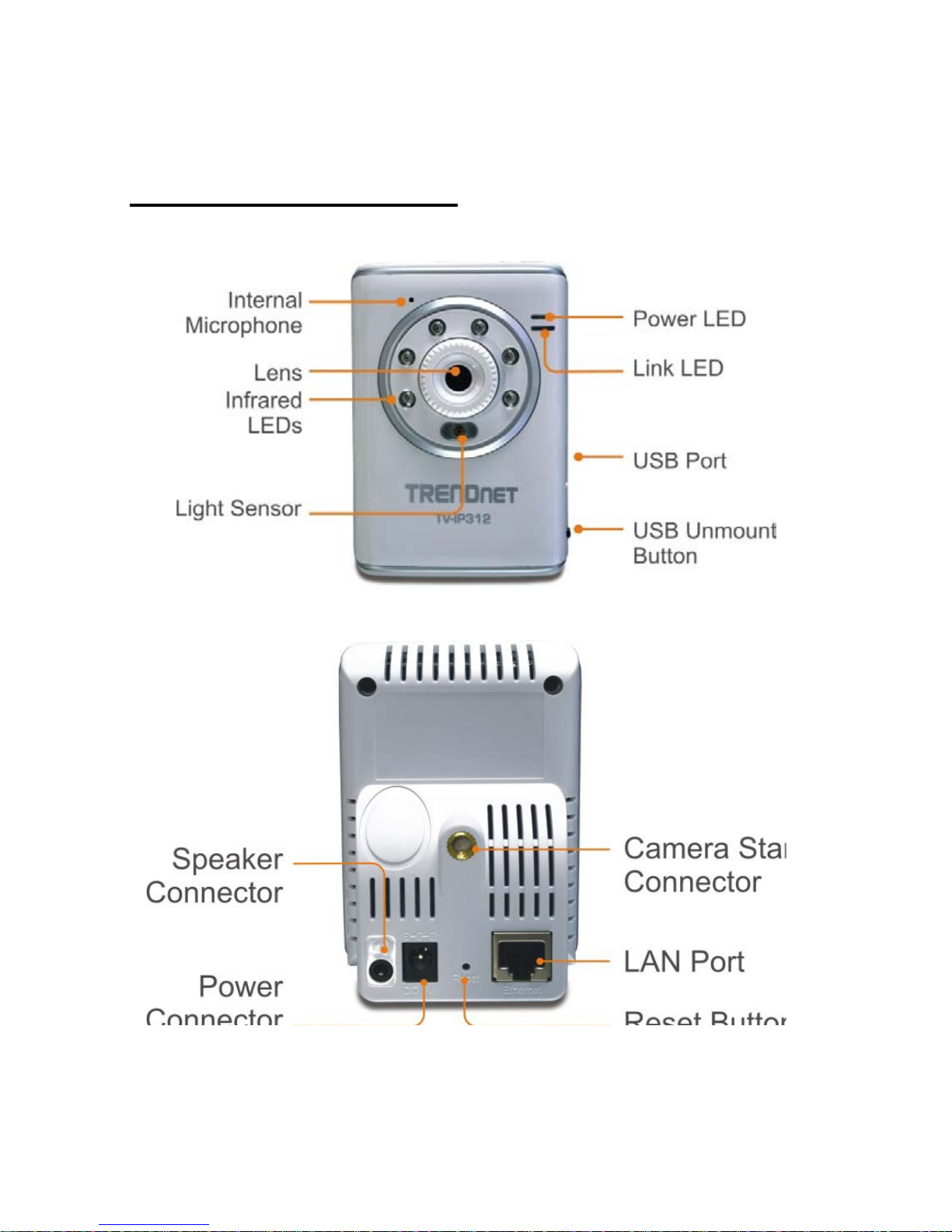
1.2 Getting to Know Your Camera
TV-IP312 (Front/Back View)

- 7 -
TV-IP312W (Front/Back View)

- 8 -
- Internal Microphone: It allows the camera to receive the sound
or voice.
- Infrared LEDs: It allows your camera to capture clear image in a
dark environment.
- Light Sensor: It is used to trigger on and off the Infrared LEDs
according the environmental light level.
- Power LED: A steady orange light indicates the camera is
powered on.
- Link LED: A flash green light indicates the camera’s network
connection correctly.
-
- Detachable Antenna (TV-IP312W only):
The detachable external antenna allows you to adjust its position
to obtain the maximum signal.
- USB Port: Connects an external USB Flash Drive, Hard Drive. It
provides the power distribution up to 500mA.
- USB Unmount Button: Removed the connected USB device
safely.
Pressing the Unmount button for four seconds, the Power LED
will start flashing. After the Power LED rsumes the steady orange
light, you can remove the USB device safely.
- Camera Stand Connection: Connects the camera with the
camera stand.

- 9 -
- Speaker Connector: Connects a external active speaker to the
camera.
- Power Connector: Connects the AC power adapter to supply
power to the camera.
- LAN Port: It is used to connect the network RJ-45 cable, which
supports the NWay protocol so that the camera can detect the
network speed automatically.
- Reset Button: Reset will be initiated when the reset button is
pressed once. The power LED begins to flash.
Factory Reset will be initiated when the reset button is pressed
continuously for three seconds or when Power LED begins to
light up. Release the reset button and the Power LED will begin to
flash.

- 10 -
1.3 Features and Benefits
MPEG4/MJPEG Dual-codec Supported
The camera provides you with excellent images by the
MPEG4/MJPEG dual-codec selectable technology, allowing you to
adjust image size and quality, and bit rate according to the
networking environment.
2-way Audio Capability
The built-in microphone of the camera provides on-the-spot
audio via the Internet, allowing you to monitor the on-site voice.
In addition, you can connect an external speaker to the camera to
speak through the camera; the camera is embedded with an echo
cancellation processor to provide a better sound quality.
Day & Night Surveillance Supported
The six Infrared LEDs around the standard lens assembly enable
the camera to capture crystal clear images in the dark
environment or at night. When the Light Sensor detects the
environmental light level becomes low, the camera captures the
images in black & white mode using these infrared LEDs.
Supports Multiple Profiles
The camera supports multiple profiles simultaneously, so that you
can separately set up different image settings (such as image
quality and frame rate) for the three video types of the camera:
MPEG4, MJPEG, and 3GPP.
Supports RTSP
The camera supports RTSP (Real Time Streaming Protocol), which
is a technology that allows you to view streaming media via the
network. You can view the real-time video with the Quick Time
player or RealPlayer. To view the real-time streaming image on
your computer, open the Web browser and enter the RTSP link:
rtsp://(IP address of the camera)/mpeg4
.

- 11 -
Remote Control Supported
By using a standard Web browser or the bundled SecurView™
software application, the administrator can easily change the
configuration of the camera via Intranet or Internet. In addition,
the camera can be upgraded remotely when a new firmware is
available. The users are also allowed to monitor the image and
take snapshots via the network.
Supports Connection to the External Devices
With the auxiliary Input/Output connectors, you can connect the
camera to a variety of external devices, such as the external
speaker and the USB Flash Drive or Hard Drive.
Multiple Platforms Supported
The camera supports multiple network protocols, including
TCP/IP, SMTP Email, HTTP, and other Internet related protocols.
Therefore, you can use the camera in Windows 2000 and
Windows XP, Windows Vista
Multiple Applications Supported
Through the remote access technology, you can use the cameras
to monitor various objects and places for your own purposes.
For example, babies at home, patients in the hospital, offices and
banks, and more. The camera can capture both still images and
video clips, so that you can keep the archives and restore them at
any time.

- 12 -
1.4 System Requirement
Networking
LAN: 10Base-T Ethernet or 100Base-TX Fast Ethernet.
WLAN: IEEE 802.11b/g.
Accessing the Camera using Web Browser
Platform: Microsoft® Windows® 7/Vista/XP/2000
CPU: Intel Pentium III 350MHz or above
RAM: 128MB
Resolution: 800x600 or above
Browser: Microsoft® Internet Explorer 6.0 or above
Accessing the Camera using SecurView™ Software View
Platform: Microsoft® Windows® 7 (32-bit)/Vista (32-bit)/XP (32-
bit)/2000
Hardware Requirement:
1 camera connected: Intel Pentium 4 1GHz; 512MB RAM
2 ~ 4 cameras connected: Intel Pentium 4 1.3GHz; 512MB RAM
5 ~ 8 cameras connected: Intel Pentium 4 2.4GHz; 1GB RAM
9 ~ 16 cameras connected: Intel Pentium 4 3.4GHz; 2GB RAM
Resolution: 1024x768 or above
NOTE If you connect multiple cameras to monitor various places
simultaneously, you are recommended to use a higher
performance computer.

- 13 -
CHAPTER 2
HARDWARE INSTALLATION
2.1 Installing the Camera Stand
The camera comes with a camera stand, which uses a swivel ball
screw head to lock the camera. When the camera stand is attached,
you can place the camera anywhere by mounting the camera through
the three screw holes located in the base of the camera stand.
The Camera Stand

- 14 -
2.2 Connecting the Camera to LAN/WLAN
Connects an Ethernet cable to the
LAN port located on the Camera’s
real panel, and then attaches it to the
network.
Connects an antenna to the antenna
connector. (TV-IP312W only)
Attach the external power supply to
the DC power input connector
located on Camera’s real Panel, and
then connect it to your local power
supply.
NOTE Please configure the wireless setting via the wire connection.

- 15 -
2.3 Applications of the Camera
The camera can be applied in multiple applications, including:
Monitor local and remote places and objects via Internet or
Intranet.
Capture still images and video clips remotely.
Upload images or send email messages with the still images
attached.
The following diagram explains one of the typical applications for
your camera and provides a basic example for installing the camera.

- 16 -
CHAPTER 3
ACCESSING THE CAMERA
3.1 Using IP Setup
The camera comes with a conveniently utility, IP Setup, which is
included in the Installation CD-ROM, allowing you to search the
camera on your network easily.
1. Insert the Installation CD-ROM into your computer’s CD-ROM
drive to initiate the Auto-Run program.
2. Click the IP Setup from the Auto-Run menu screen. Then IP
Setup Wizard will appear. Click “Next” when the Welcome to the
IPSetup Setup Wizard appears.

- 17 -
3. Click “Browse” to choose the desired destination location. By
default, the destination location is C:\Program
Files\TRENDnet\IPSetup. Then Click “Next”.
4. Click “Next” to confirm the IPSetup software to be installed to the
computer.

- 18 -
5. When the Installation Complete window appears, click “Finish”.

- 19 -
6. After installing the IPSetup utility, the application is automatically
installed to your computer, and creates a folder in “ Start
\Program\TRENDnet\IPSetup”.
7. Click Start > Programs > TRENDnet > IPSetup, and then click
IPSetup
8. The IPSetup window will appear. It will search the Camera within
the same network.
Camera Display Area

- 20 -
- Camera Display Area: It shows the connected camera(s) within
the same network
Double click the IP address, it will link to Camera’s Web
Configuration page.
- Change IP: Click this button to bring up the following window. It
allows you to change the IP Address. You can select either Static
IP or click DHCP. Then, enter the Administrator ID & password.
By default ID/password is: admin. When complete, click “Change”.
- Search: Click this button to search the connected camera in
the same network.”
-
Exit: Click this button to exit the program.

- 21 -
3.2 Accessing to the Camera
1. Open the Web browser on your computer (example showed in
the User’s Guide is based on the Internet Explorer)
2. Type the default IP address (192.168.10.30) and then press [Enter].
3. When the login window appears, enter the default User name
(admin) and password (admin) and press OK to access to the
main screen of the camera’s Web Configuration.

- 22 -
NOTE If you are initially access to the camera, you will be ask to install
a new plug-in for the camera. Permission request depends on
the Internet security settings of your computer. Click Yes to
proceed.
After you login into the Web Configuration of the camera, the main
page will appear as below:
The main page of the Web Configuration provides you with many
useful information and functions, including:
Night Mode
Live View Image
Live View/ Setup
Function
Compression
Camera Information
Zoom In

- 23 -
Camera Information
– Display the camera’s location and the
current date & time. The information can be modified in the Web
Configuration.
Nightmode
– Click the button to enable the “nightshot mode” to
deliver clearer images in the dark environment. However, this will
reduce the frame rate of video setting. (TV-IP312/TV-IP312W only)
Live View Image
– Displays the real-time image of the connected
camera.
Zoom In
– Click the buttons to zoom in the live view image by 1x,
2x, and 3x.
Live View/Setup Switch
– Click Setup to configure the camera.
For details, see Chapter 4.
Compression Buttons
– Select to transmit and record the video
using MPEG4 or MJPEG compression.
Function
– Use these buttons to control the audio and video
functions.
Manual Record allows you to record and save a video clip.
Snapshot allows you to capture and save a still image.
Browse allows assign the destination folder to store the
video clips and still images.
Talk allows you to speak out through the camera. Please
note only one user is allowed to use this function at the same
time.
Listen allows you receive the on-site sound and voice from
the camera.

- 24 -
3.3 Configuring the IP Address of the PC
If you are failed to access to the camera, please check the IP address of
your computer. When you connect the camera to your computer
directly to proceed with configuration of the camera, you need to set
up the IP addresses to be in the same segment for the two devices to
communicate.
1. On your computer, click Start > Control Panel to open the
Control Panel window.
2. Double-click Network Connection to open the Network
Connection window.
3. Right-click Local Area Connection and then click Properties
from the shortcut menu.
4. When the Local Area Connection Properties window appears,
select the General tab.
5. Select Internet Protocol [TCP/IP] and then click Properties to
bring up the Internet Protocol [TCP/IP] Properties window.
6. To configure a fixed IP address that is within the segment of the
camera, select the Use the following IP address option. Then,
enter an IP address into the empty field. The suggested IP address
is 192.168.10.x (x is 0~254 except 30), and the suggested Subnet
mask is 255.255.255.0.
7. When you are finished, click OK.

- 25 -
CHAPTER 4
CONFIGURING THE CAMERA
4.1 Using the Web Configuration
You can access and manage the camera through the Web browser or
from the SecurView™ software (see chapter 5 in more detail). This
chapter describes the Web Configuration, and guides you through the
configuration of the camera by using the web browser.
To configure the camera, click Setup on the main page of Web
Configuration. The Web Configuration will start from the Basic page.

- 26 -
The Web Configuration contains the settings that are required for the
camera in the left menu bar, including Smart Wizard, Basic, Network,
Video/Audio, Event Server, Motion detect, Event Config, Tools,
USB, and Information.
4.2 Using Smart Wizard
The camera’s Smart Wizard lets you configure your camera easily and
quickly. The wizard will guide you through the necessary settings with
detailed instructions on each step.
To start the wizard, click Smart Wizard in the left menu bar.

- 27 -
Step 1. Camera Settings
Step 2. IP Settings
Select the IP setting
according to your
network: DHCP,
Static IP, or PPPoE.
Enter Camera
name, Location,
New Admin
password and
enter again to
confirm Admin
password

- 28 -
Step 3. Email Settings
Enter the required
information to be
able to send email
with image.

- 29 -
Step 4. Wireless Networking (for TV-IP212W/TV-IP312W only)
Select Enable to
enable the wireless
function of the
camera, and then
complete the
required settings.
 Loading...