

Page 1
TRENDnet User’s Guide
Cover Page
Page 2

TRENDnet User’s Guide
Table of Contents
i
Contents
Products Overview .......................................................................... 1
TI-PG541i ....................................................................................................................... 1
TI-PG102i ....................................................................................................................... 1
TI-G160WS ..................................................................................................................... 2
Products Hardwares and Features ................................................... 3
Management Host ............................................................................................. 24
MAC Management ...................................................................................................... 26
Static MAC Settings............................................................................................ 26
Age Time Settings .............................................................................................. 28
MAC Table ......................................................................................................... 28
Port Mirror ................................................................................................................... 29
Port Settings ................................................................................................................ 31
PoE ................................................................................................................................. 3
TI-PG541i ....................................................................................................................... 3
TI-PG102i ....................................................................................................................... 6
Non-PoE ......................................................................................................................... 9
TI-G160WS ..................................................................................................................... 9
Switch Installation ........................................................................ 12
DIN-Rail Installation ..................................................................................................... 12
Install power supply connections ................................................................................ 13
SFP Transceiver/Optical Cable Installation .................................................................. 13
Basic IP Configuration .................................................................................................. 14
Connect additional devices to your switch .................................................................. 15
Accessing switch management interfaces ...................................... 16
Access your switch command line interface................................................................ 16
CLI Command Modes ......................................................................................... 16
Access your switch web management page ................................................................ 18
System Information....................................................................... 19
Basic Settings ................................................................................ 20
General Settings .......................................................................................................... 20
System ............................................................................................................... 20
Jumbo Frame ..................................................................................................... 21
SNTP ................................................................................................................... 22
General Settings ................................................................................................ 32
Information ........................................................................................................ 34
Advanced Settings ........................................................................ 35
Bandwidth Control ...................................................................................................... 35
QoS .................................................................................................................... 35
Rate Limitation .................................................................................................. 41
IGMP Snooping ............................................................................................................ 44
IGMP Snooping .................................................................................................. 44
Multicast Address .............................................................................................. 47
VLAN ............................................................................................................................ 50
Port Isolation ..................................................................................................... 50
802.1Q VLAN ...................................................................................................... 51
MAC VLAN ......................................................................................................... 55
DHCP Options .............................................................................................................. 56
DHCP Relay .................................................................................................................. 59
EEE (Energy Efficient Ethernet) .................................................................................... 62
Link Aggregation .......................................................................................................... 63
Loop Detection ............................................................................................................ 67
Modbus ........................................................................................................................ 70
Power over Ethernet ................................................................................................... 74
STP ............................................................................................................................... 79
Security ........................................................................................ 87
© Copyright 2019 TRENDnet. All Rights Reserved.
Page 3

TRENDnet User’s Guide
Table of Contents
ii
IP Source Guard ........................................................................................................... 87
Device Management.................................................................................................. 125
Binding Table ..................................................................................................... 92
ARP Inspection ................................................................................................... 94
Filter Table ......................................................................................................... 96
Access Control List (ACL) .............................................................................................. 97
802.1x ........................................................................................................................ 101
Port Security .............................................................................................................. 106
Monitor ...................................................................................... 108
Alarm ......................................................................................................................... 108
Port Statistics ............................................................................................................. 108
Port Utilization ........................................................................................................... 109
RMON Statistics ......................................................................................................... 110
SFP Information ......................................................................................................... 110
Traffic Monitor ........................................................................................................... 111
Management .............................................................................. 113
SNMP ......................................................................................................................... 113
SNMP Trap ....................................................................................................... 115
Auto Provision ........................................................................................................... 116
Mail Alarm ................................................................................................................. 117
Maintenance .............................................................................................................. 120
System Log ................................................................................................................. 123
User Account ............................................................................................................. 123
Toplogy Map .............................................................................................................. 129
Technical Specifications .............................................................. 130
TI-PG541i ................................................................................................................... 130
TI-PG102i ................................................................................................................... 133
TI-G160WS ................................................................................................................. 136
Troubleshooting ......................................................................... 139
Appendix .................................................................................... 140
© Copyright 2019 TRENDnet. All Rights Reserved.
Page 4
TRENDnet User’s Guide
Industrial Managed Switch Series
1
Products Overview
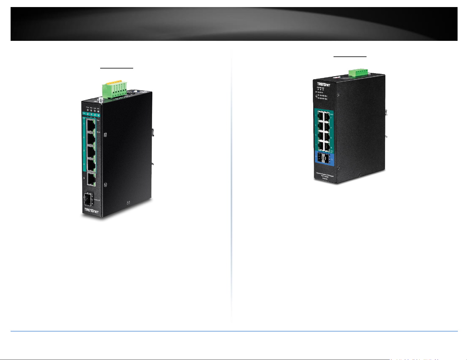
TI-PG541i
TRENDnet’s 6-Port Hardened Industrial Gigabit PoE+ Layer 2 Managed DIN-Rail Switch,
model TI-PG541i, has four Gigabit PoE+ ports, one Gigabit port, one Gigabit SFP slot and
a 120W PoE budget. The switch is equipped with an IP30 rated metal enclosure and
designed to withstand a high degree of vibration, shock, protection against
ESD/EMI/surge, and operate within a wide temperature range (- 40 – 70 °C (- 40 - 158
°F)) for harsh environments. L2 management include features such as PoE port control,
VLAN, multicast, and QoS which allow for network integration flexibility.
TRENDnet’s 10-Port Industrial Gigabit L2 Managed PoE+ DIN-Rail Switch, model TIPG102i, features eight Gigabit PoE+ ports with a 240W PoE budget, and includes two
SFP slots that support both 100Base-FX and 1000Base-FX modules for long distance fiber
applications. The hardened switch is equipped with an IP30 rated metal enclosure,
designed to withstand a high degree of vibration and shock, while operating within a
wide temperature range of -40° – 75° C (-40° – 167° F) for industrial environments.
Advanced traffic management controls, troubleshooting, and SNMP monitoring support
make this a powerful solution for SMB networks.
TI-PG102i
© Copyright 2019 TRENDnet. All Rights Reserved.
Page 5
TRENDnet User’s Guide
Industrial Managed Switch Series
2
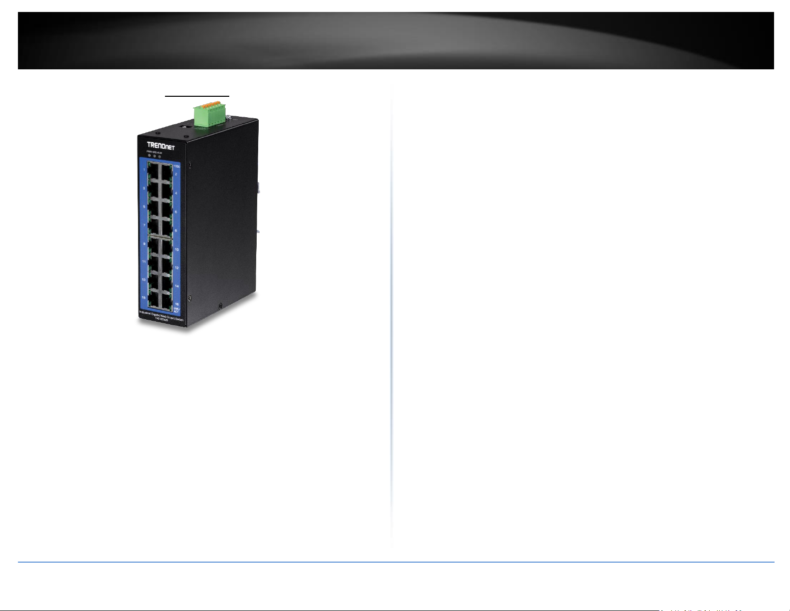
TI-G160WS
TRENDnet’s 16-Port Industrial Gigabit Web Smart DIN-Rail Switch, model TI-G160WS,
delivers advanced management features with a 32Gbps switching capacity. Users are
able to connect sixteen devices to the switch for high speed gigabit network
connections. The switch is equipped with an IP30 rated metal enclosure, designed to
withstand a high degree of vibration and shock, while operating within a wide
temperature range of -40° – 75° C (-40° – 167° F) for industrial environments. Advanced
traffic management controls, troubleshooting, and SNMP monitoring support make this
a powerful solution for SMB networks.
© Copyright 2019 TRENDnet. All Rights Reserved.
Page 6
TRENDnet User’s Guide
Industrial Managed Switch Series
3
LED
State
Status
PWR
(Green)
ON
When the PWR LED is on, the device is using the primary
power input source.
OFF
Primary power input source is off, disconnected, or has
failed.
RPS
(Green)
ON
When the RPS LED lights on, the device is using the
redundant power input source.
OFF
Redundant power input source is off, disconnected or has
failed.
ALM
(Red)
ON
Indicates alarm has been triggered on DIP switch settings and
signal sent out through ALM terminals on terminal block to
third party alarm device.
OFF
No alarm triggered.
POST
(Green)
ON
Device is ready and completed boot process.
OFF
Device is not ready.
SFP Slot 6
(Green)
ON
SFP link is connected.
BLINKING
Data is transmitting/receiving.
OFF
SFP link is disconnected.
PoE Ports 1-4
(Green)
ON
PoE supplied to Ethernet port.
OFF
No PoE supplied to Ethernet port.
Ports 1-5
1000M
(Green)
10/100M
(Off)
ON
Ethernet port is connected.
BLINKING
Data is transmitting/receiving.
OFF
Ethernet port is not connected.
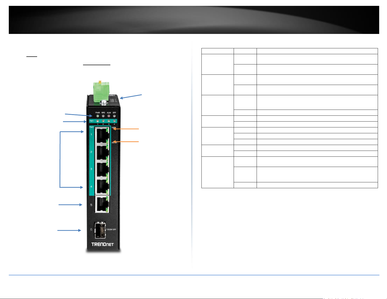
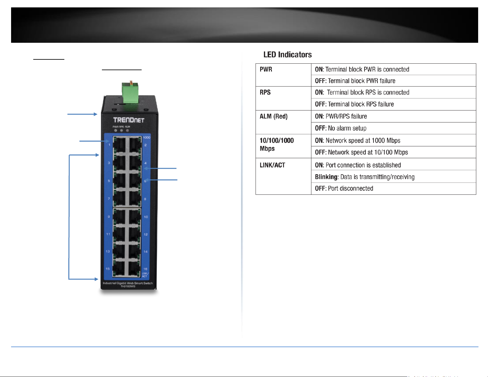
LED Indicators
PoE+ Gigabit
RJ-45 ports
10/100/1000
Mbps per port
LED indicator
LINK/ACT per
port LED
indicator
IP30 Rated
Housing
PoE LEDs
SFP+ Slots
Gigabit
RJ-45 port
Products Hardwares and Features
LED Indicators
PoE
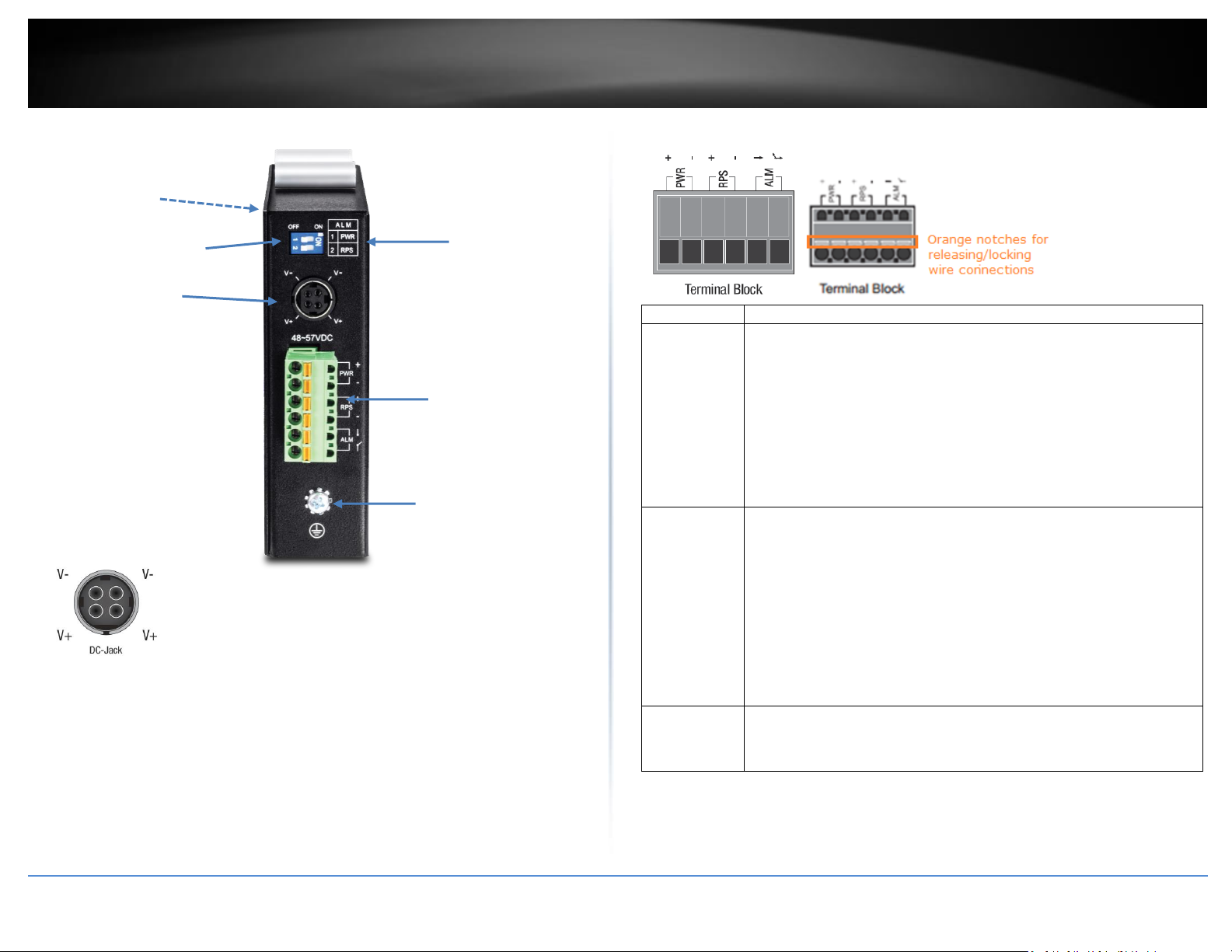
TI-PG541i
Front View
© Copyright 2019 TRENDnet. All Rights Reserved.
Ports 1-4 – Designed to operate at 10Mbps, 100Mbps, or Gigabit speed in both
half-duplex and full-duplex transfer modes. Supports Auto MDI-X and capable
of delivering up to 30W (802.3at PoE+) per port.
Port 5 - Designed to operate at 10Mbps, 100Mbps, or Gigabit speed in both
half-duplex and full-duplex transfer modes. Supports Auto MDI-X
SFP Slot 6 – Designed to operate at Gigabit speeds.
Reset/Reboot Button – Push the button for 10 seconds and release to reset the
switch to factory defaults. Push the button for 3 seconds and release to reboot.
Grounding point/screw – The switch chassis can also be connected to a known
ground point for additional safety and protection. (grounding wire not
included)
Note: For any unused ports or SFP slots, it is recommended to leave the rubber plugs
installed during operation.
Page 7
TRENDnet User’s Guide
Industrial Managed Switch Series
4
Input/Ouput
Function
PWR Input
(+) & (-)
Connects primary power source (ex. external power supply) to power the
device. Device will obtain power from this input first priority if available.
Please make sure to power supplies are turned off before wiring in.
Use a flat-head screw driver to push the orange notches in order release
the wiring connections. While holding in released position, insert the
wiring into the connection inputs from the external power supply and
release the orange notch to lock in the wire connections.
Please ensure that the external power supply is supplying within the
range of 48VDC ~ 57VDC @ 120W or above. 130W for max. PoE+ power.
Please note power supply is sold separately (model: TI-24048)
Device supports overload current protection and reverse polarity
protection.
RPS Input
(+) & (-)
Connects redundant power source (ex. external power supply) to power
the device. Device will obtain power from this input secondary priority if
primary power input is not available or has failed.
Please make sure to power supplies are turned off before wiring in.
Use a flat-head screw driver to push the orange notches in order release
the wiring connections. While holding in released position, insert the
wiring into the connection inputs from the external power supply and
release the orange notch to lock in the wire connections.
Please ensure that the external power supply is supplying within the
range of 48VDC ~ 57VDC @ 120W or above. 130W for max. PoE+ power.
Please note power supply is sold separately (model: TI-24048)
Device supports overload current protection and reverse polarity
protection.
ALM Output
Connects external alarm and sends output signal if fault is detected
based on DIP switch settings.
Supports an output with current carrying capacity of 1A @ 24V DC.
DIP Switches
Reset Button
(bottom of unit)
Ground point
6-pin terminal
block (PWR,
RPS, ALM)
DIP switch
definition
DC Jack
(optional, see below)
Top View
DC Jack Input for External Power Adapter
The device includes a DC Jack for an external power adapter and can
also be used as an additional redundant power supply (RPS) input.
Please ensure that the external power adapter is supplying 48VDC @
120W or above. 130W for max. PoE+ power. Please note power
adapter is sold separately (model: 48VDC3000)
**Supported power supplies: TI-S12024 (120W), TI-S24048 (240W), TI-S48048 (480W).
Lower wattage power supplies may be used but may result in decreased PoE power
© Copyright 2019 TRENDnet. All Rights Reserved.
*Please note power supply is sold separately*
budget**
6-pin Removable Terminal Block
Page 8
TRENDnet User’s Guide
Industrial Managed Switch Series
5
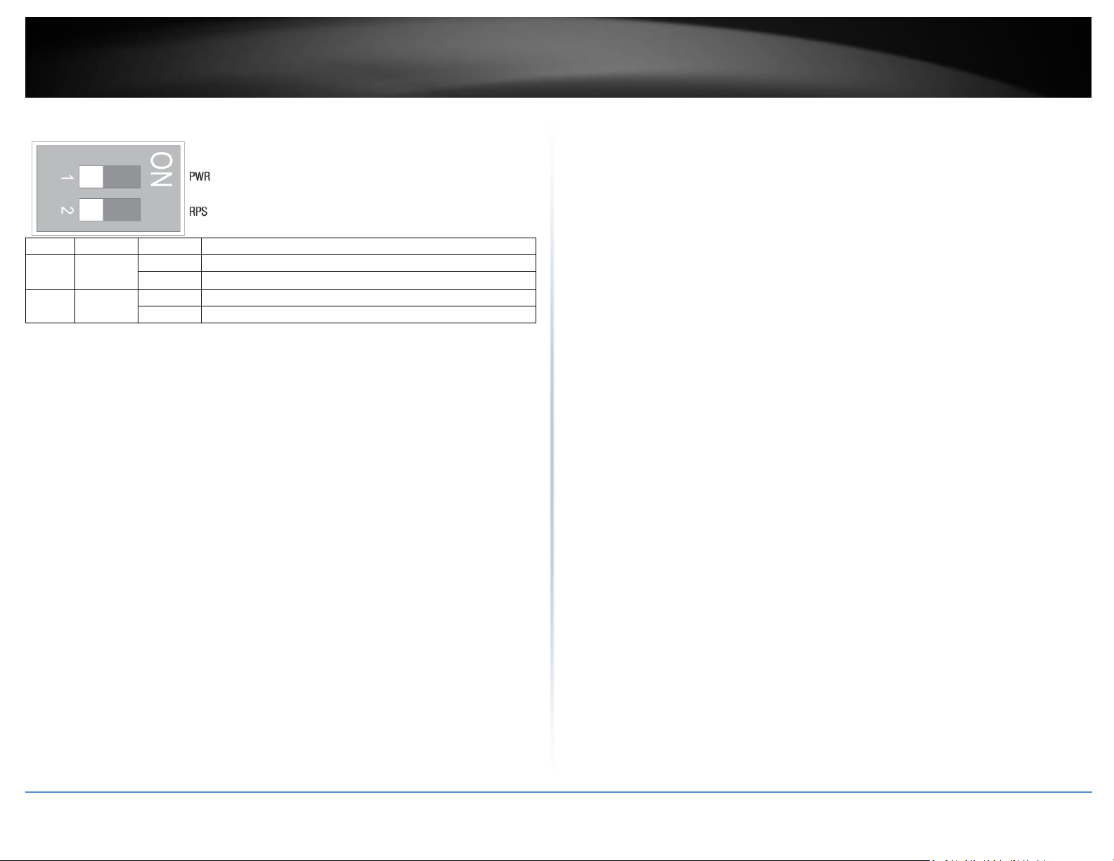
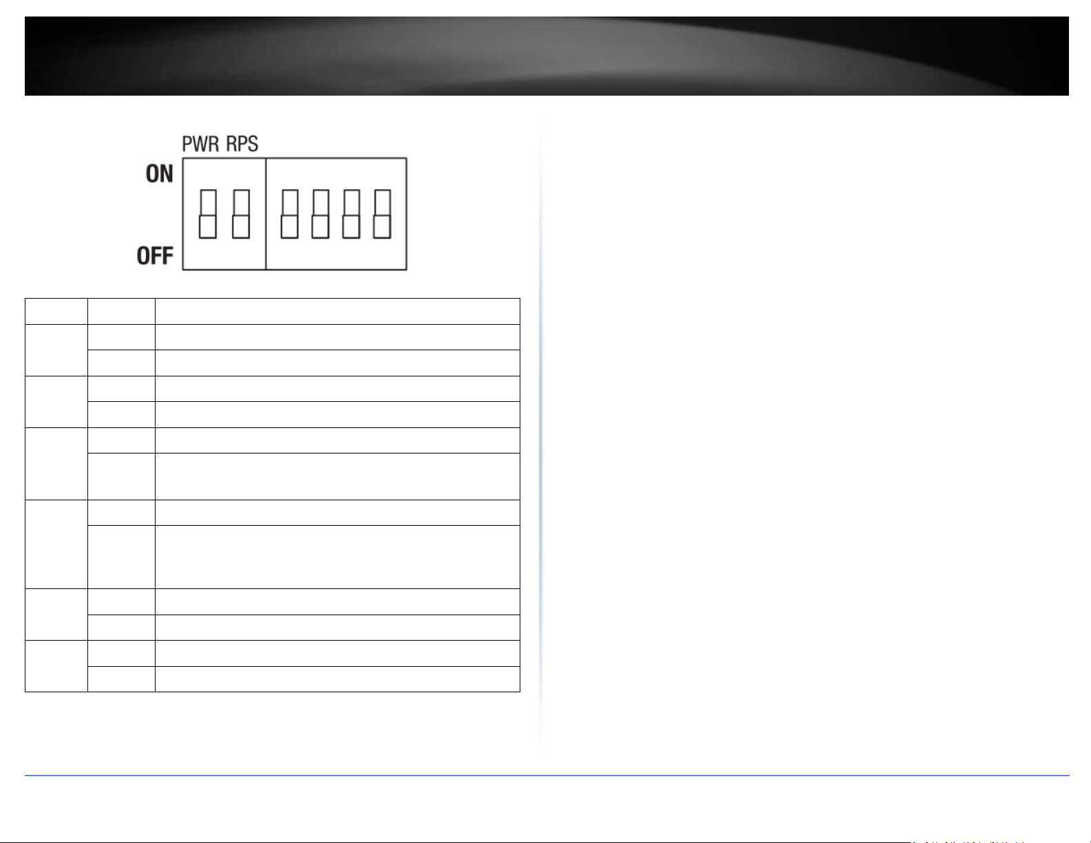
DIP No
Name
State
Status
1
PWR
ON
Primary power input source alarm trigger enabled.
OFF
Primary power input source alarm trigger disabled.
2
RPS
ON
Redundant power input source alarm trigger enabled.
OFF
Redundant power input source alarm trigger disabled.
ALM DIP Switches
© Copyright 2019 TRENDnet. All Rights Reserved.
Page 9
TRENDnet User’s Guide
Industrial Managed Switch Series
6
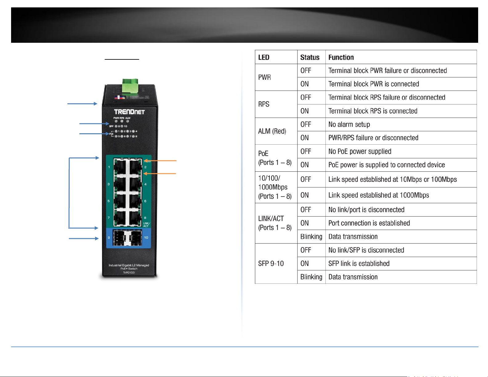
LED Indicators
PoE+ Gigabit
RJ-45 ports
10/100/1000
Mbps per port
LED indicator
LINK/ACT per
port LED
indicator
IP30 Rated
Housing
PoE LEDs
SFP+ Slots
TI-PG102i
Front View
PoE+ Ports 1-8 – Designed to operate at 10Mbps, 100Mbps, or Gigabit speed in
both half-duplex and full-duplex transfer modes while simultaneously providing
power to supported PoE devices. Supports Auto MDI-X.
Reset Button – Push the button for 5-10 seconds and release to reboot.
Grounding point/screw – The switch chassis can also be connected to a known
ground point for additional safety and protection. (grounding wire not
included)
© Copyright 2019 TRENDnet. All Rights Reserved.
Page 10
TRENDnet User’s Guide
Industrial Managed Switch Series
7
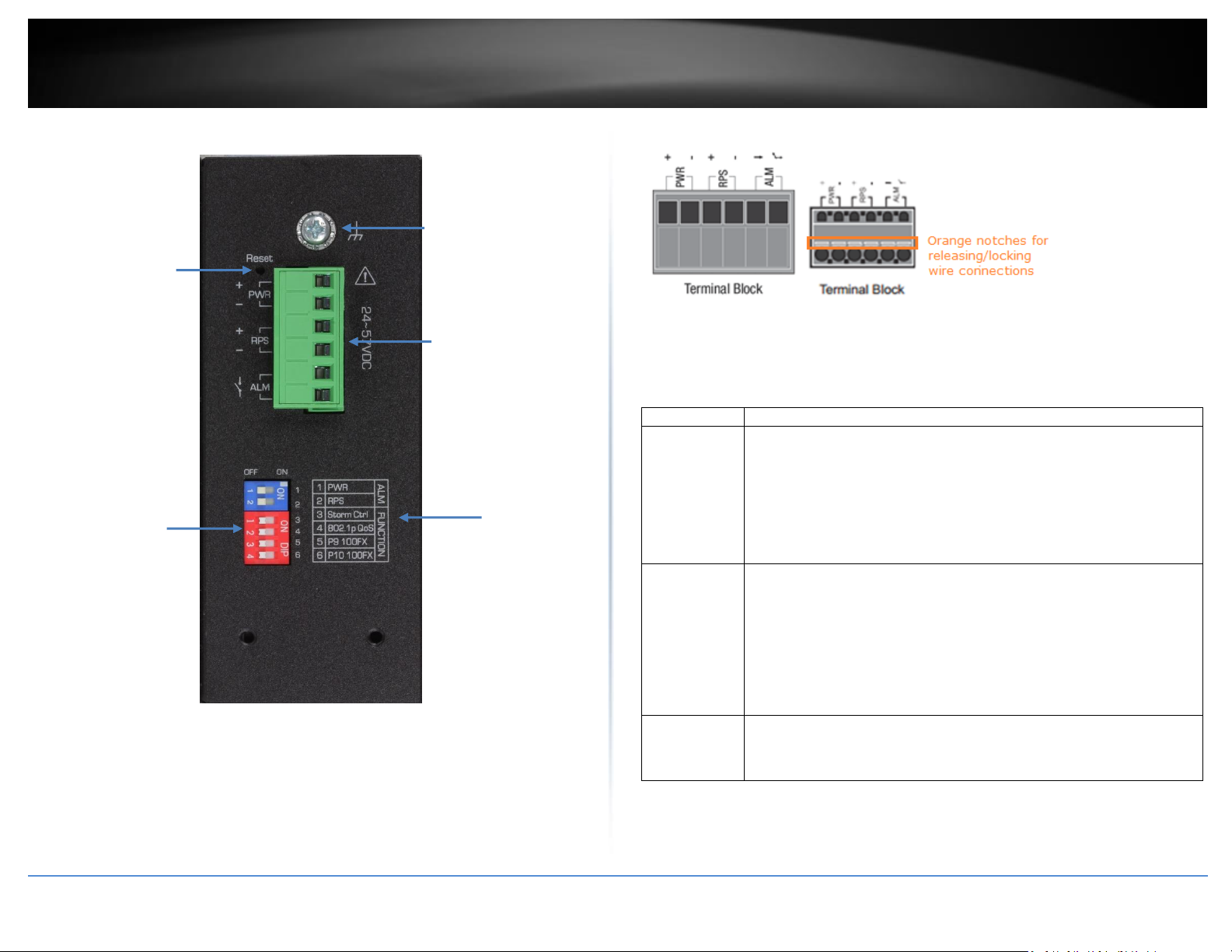
Input/Output
Function
PWR Input
(+) & (-)
Connects primary power source (ex. external power supply) to power the
device. Device will obtain power from this input first priority if available.
Please make sure to power supplies are turned off before wiring in.
Use a flat-head screw driver to push the orange notches in order release
the wiring connections. While holding in released position, insert the
wiring into the connection inputs from the external power supply and
release the orange notch to lock in the wire connections.
Device supports overload current protection and reverse polarity
protection.
RPS Input
(+) & (-)
Connects redundant power source (ex. external power supply) to power
the device. Device will obtain power from this input secondary priority if
primary power input is not available or has failed.
Please make sure to power supplies are turned off before wiring in.
Use a flat-head screw driver to push the orange notches in order release
the wiring connections. While holding in released position, insert the
wiring into the connection inputs from the external power supply and
release the orange notch to lock in the wire connections.
Device supports overload current protection and reverse polarity
protection.
ALM Output
Connects external alarm and sends output signal if fault is detected
based on DIP switch settings.
Supports an output with current carrying capacity of 1A @ 24V DC.
DIP Switches
Reset Button
Ground point
6-pin terminal
block (PWR,
RPS, ALM)
DIP switch
definition
Top View
*Please note power supply is sold separately*
**Supported power supplies: TI-S12024 (120W), TI-S24048 (240W), TI-S48048 (480W).
Lower wattage power supplies may be used but may result in decreased PoE power
© Copyright 2019 TRENDnet. All Rights Reserved.
budget**
6-pin Removable Terminal Block
Note: Turn off the power before connecting modules or wires.
Calculate the maximum possible current in each power wire and common wire. Observe
all electrical codes dictating the maximum current allowable for each wire size. If current
go above the maximum ratings, the wiring could overheat, causing serious damage to
your equipment.
Page 11
TRENDnet User’s Guide
Industrial Managed Switch Series
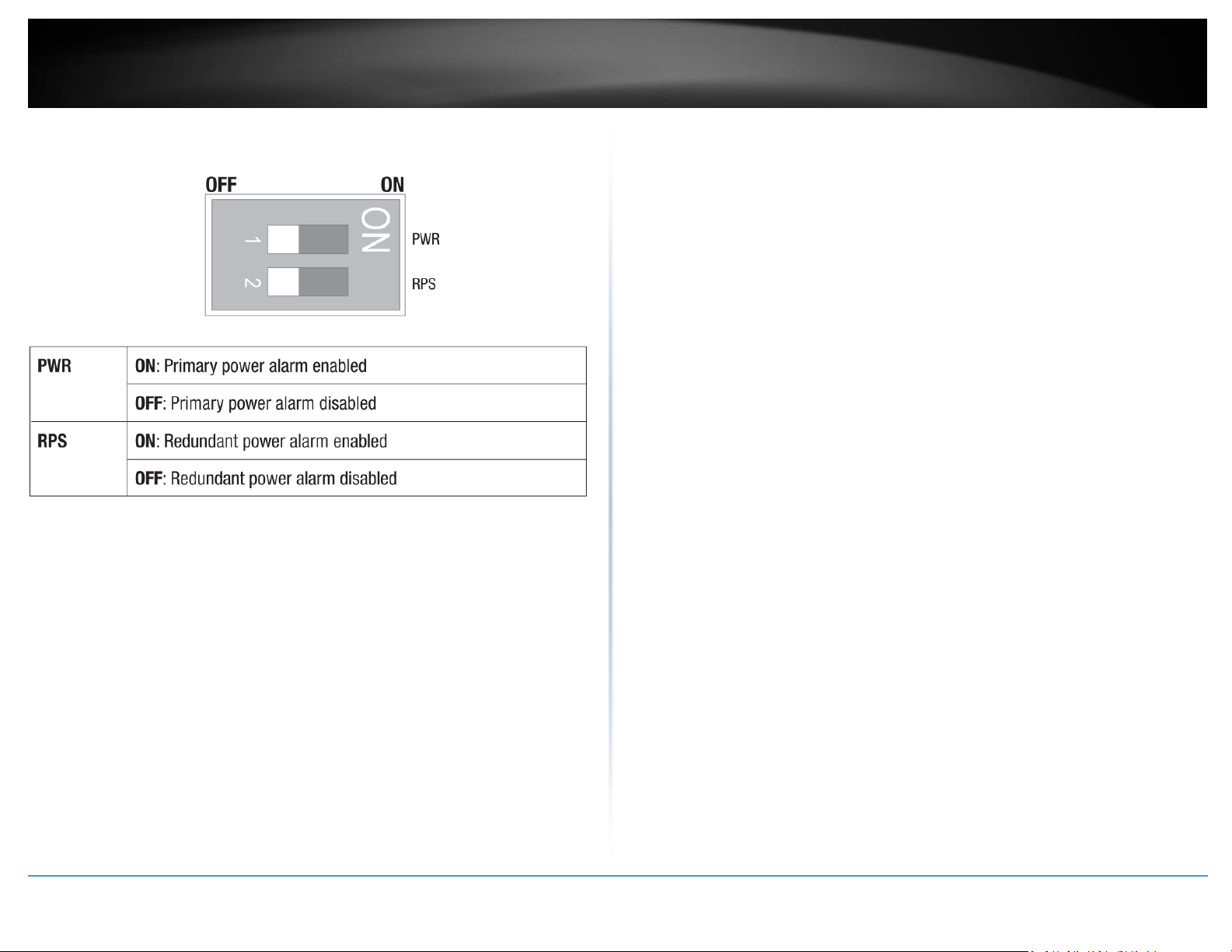
8
Switch
Status
Function
1
OFF
Disable alarm relay for PWR power input
ON
Enable alarm relay for power failure on PWR power input
2
OFF
Disable alarm relay for RPS power input
ON
Enable alarm relay for power failure on RPS power input
3
OFF
Storm control managed by switch configuration
ON
Enable storm control (Broadcast and DLF rate set to 300pps)
Takes precedence over storm control switch configuration
4
OFF
802.1p QoS managed by switch configuration
ON
Enable 802.1p QoS on ports 1 and 2 (Set CoS priority to tag 4
on ports 1 and 2)
Takes precedence over 802.1p QoS switch configuration
5
OFF
Port 9 SFP set to Gigabit speed full duplex
ON
Port 9 SFP set to 100Mbps speed full duplex
6
OFF
Port 10 SFP set to Gigabit speed full duplex
ON
Port 10 SFP set to 100Mbps speed full duplex
ALM DIP Switches
© Copyright 2019 TRENDnet. All Rights Reserved.
Page 12
TRENDnet User’s Guide
Industrial Managed Switch Series
9
LED Indicators
Gigabit
RJ-45 ports
10/100/1000
Mbps per port
LED indicator
LINK/ACT per
port LED
indicator
IP30 Rated
Housing
Non-PoE
TI-G160WS
Front View
Ports 1-16 – Designed to operate at 10Mbps, 100Mbps, or Gigabit speed in
both half-duplex and full-duplex transfer modes. Supports Auto MDI-X.
Reboot Button – Push the button for 3 seconds and release to reboot.
Grounding point/screw – The switch chassis can also be connected to a known
ground point for additional safety and protection. (grounding wire not
included)
© Copyright 2019 TRENDnet. All Rights Reserved.
Page 13
TRENDnet User’s Guide
Industrial Managed Switch Series
10
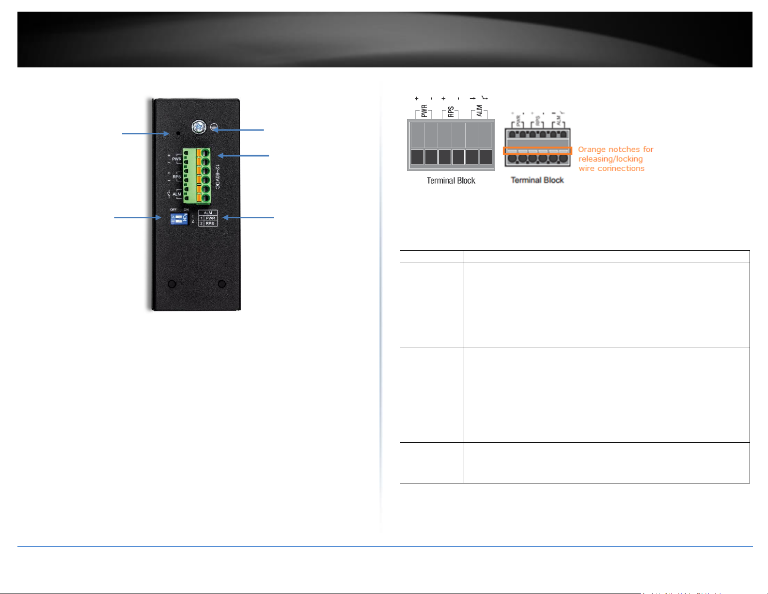
Input/Output
Function
PWR Input
(+) & (-)
Connects primary power source (ex. external power supply) to power the
device. Device will obtain power from this input first priority if available.
Please make sure to power supplies are turned off before wiring in.
Use a flat-head screw driver to push the orange notches in order release
the wiring connections. While holding in released position, insert the
wiring into the connection inputs from the external power supply and
release the orange notch to lock in the wire connections.
Device supports overload current protection and reverse polarity
protection.
RPS Input
(+) & (-)
Connects redundant power source (ex. external power supply) to power
the device. Device will obtain power from this input secondary priority if
primary power input is not available or has failed.
Please make sure to power supplies are turned off before wiring in.
Use a flat-head screw driver to push the orange notches in order release
the wiring connections. While holding in released position, insert the
wiring into the connection inputs from the external power supply and
release the orange notch to lock in the wire connections.
Device supports overload current protection and reverse polarity
protection.
ALM Output
Connects external alarm and sends output signal if fault is detected
based on DIP switch settings.
Supports an output with current carrying capacity of 1A @ 24V DC.
DIP Switches
Reboot Button
Ground point
6-pin terminal
block (PWR,
RPS, ALM)
DIP switch
definition
Top View
*Please note power supply is sold separately*
**Supported power supplies: TI-M6024, TI-S12024 (120W), TI-S24048 (240W) **
6-pin Removable Terminal Block
Note: Turn off the power before connecting modules or wires.
Calculate the maximum possible current in each power wire and common wire. Observe
all electrical codes dictating the maximum current allowable for each wire size. If current
go above the maximum ratings, the wiring could overheat, causing serious damage to
your equipment.
© Copyright 2019 TRENDnet. All Rights Reserved.
Page 14
TRENDnet User’s Guide
Industrial Managed Switch Series
11
ALM DIP Switches
© Copyright 2019 TRENDnet. All Rights Reserved.
Page 15
TRENDnet User’s Guide
Industrial Managed Switch Series
12
Switch Installation
DIN-Rail Installation
The site where the switch will be installed may greatly affect its performance. When
installing, consider the following pointers:
Note: The switch model may be different than the one shown in the example
illustrations.
Install the switch in the appropriate location. Please refer to the technical
specifications at the end of this manual for the acceptable operating temperature
and humidity ranges.
Install the Switch in a site free from strong electromagnetic field generators (such
as motors), vibration, dust, and direct exposure to sunlight.
Install the switch in a location that is not affected by strong electromagnetic field
generators (such as motors), vibration, dust, and direct sunlight.
Leave at least 10cm of space at the front and rear of the switch for ventilation.
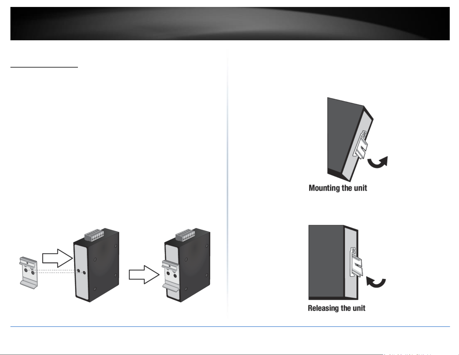
Fasten the DIN-Rail bracket to the rear of the switch using the included
fasteners/screws.
Note: The DIN-Rail bracket may already be installed to your switch when received.
The movable clip at the top of the DIN-Rail bracket should be on top.
The switch can be installed to a 35mm (W) DIN-Rail located in cabinet, rack, or
enclosure.
To mount the switch to a DIN-Rail using the attached DIN-Rail bracket, position the
switch in front of the DIN-Rail and hook the bracket over the top of the rail.
Then rotate the switch downward towards the rail until your hear a click indicating the
bracket is secure and locked into place.
To unmount the switch from the DIN-Rail, slightly pull the switch downwards to clear
the bottom of the DIN-Rail and rotate away from DIN-Rail to unmount.
© Copyright 2019 TRENDnet. All Rights Reserved.
Page 16
TRENDnet User’s Guide
Industrial Managed Switch Series
13
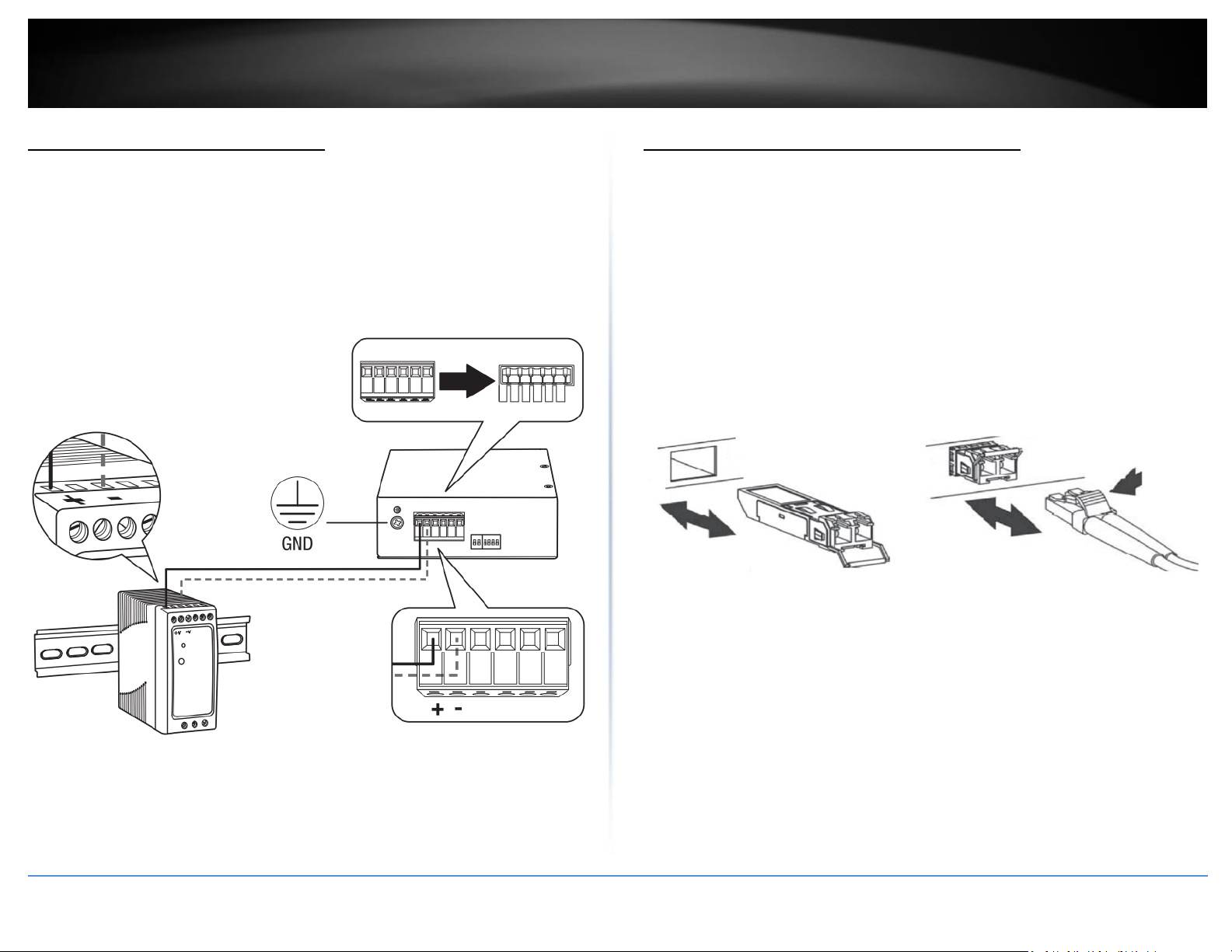
Install power supply connections
Connect the power supply (sold separate, e.g. TRENDnet TI-S24048) to the switch
terminal block as shown below.
Optional: The switch chassis can also be connected to a known ground point for
additional safety and protection (grounding wire not included).
Note: Polarities V+ and V- should match between power supply and connections to
switch terminal block.
Note: The models in the image may be different than your specific model.
SFP Transceiver/Optical Cable Installation
1. Remove the rubber plug from the SFP slot.
Note: For any unused ports or SFP slots, it is recommended to leave the
rubber plugs installed during operation.
2. Slide the selected SFP module into the selected SFP slot (Make sure the SFP
module is aligned correctly with the inside of the slot)
3. Insert and slide the module into the SFP slot until it clicks into place.
4. Remove any rubber plugs that may be present in the SFP module’s slot.
5. Align the fiber cable’s connector with the SFP module’s mouth and insert the
connector
6. Slide the connector in until a click is heard
7. If you want to pull the connector out, first push down the release clip on top
of the connector to release the connector from the SFP module
To properly connect fiber cabling: Check that the fiber terminators are clean. You can
clean the cable plugs by wiping them gently with a clean tissue or cotton ball moistened
with a little ethanol. Dirty fiber terminators on fiber optic cables will impair the quality of
the light transmitted through the cable and lead to degraded performance on the port.
© Copyright 2019 TRENDnet. All Rights Reserved.
Note: When inserting the cable, be sure the tab on the plug clicks into position to
ensure that it is properly seated.
Page 17
TRENDnet User’s Guide
Industrial Managed Switch Series
14
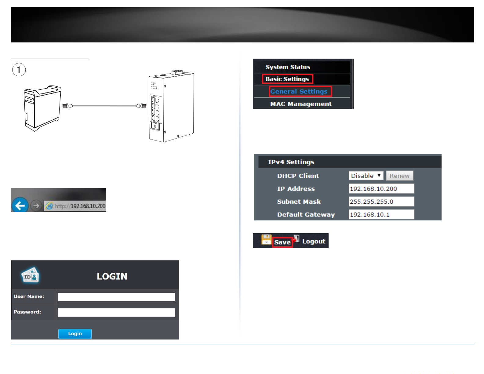
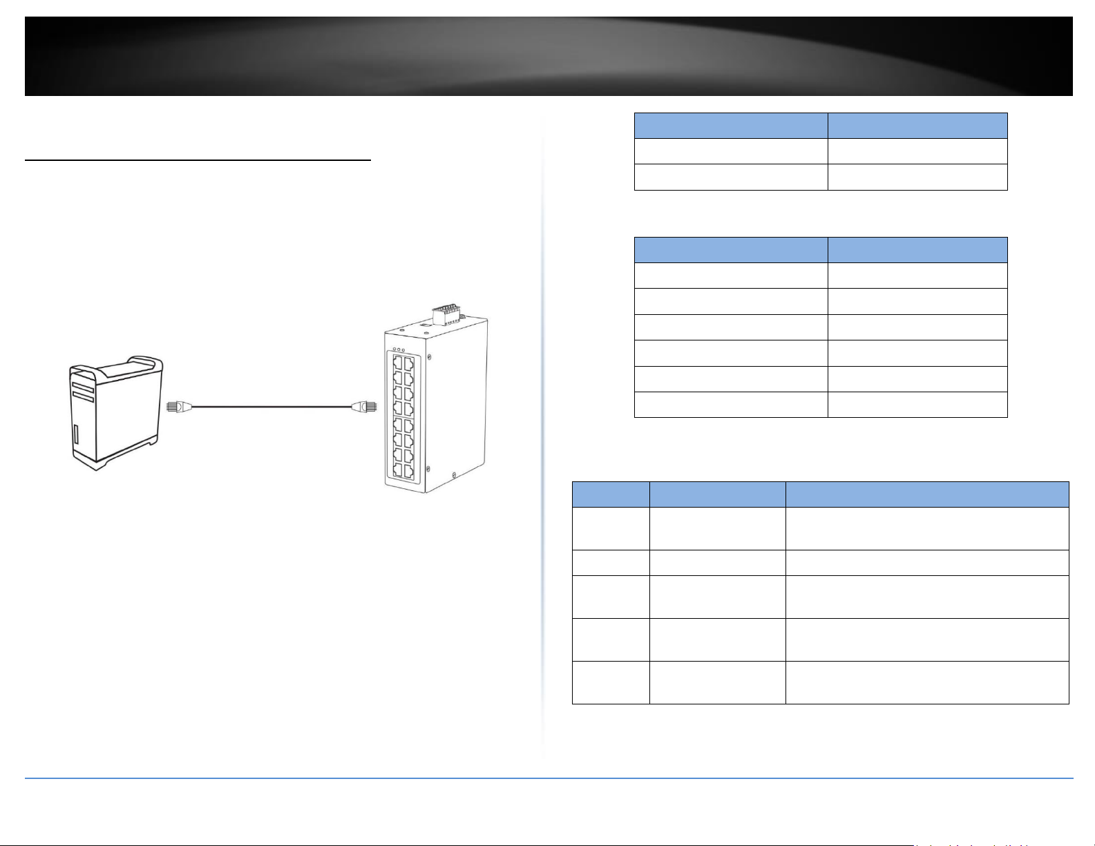
Basic IP Configuration
2. Assign a static IP address to your computer’s network adapter in the subnet of
192.168.10.x (e.g. 192.168.10.25) and a subnet mask of 255.255.255.0.
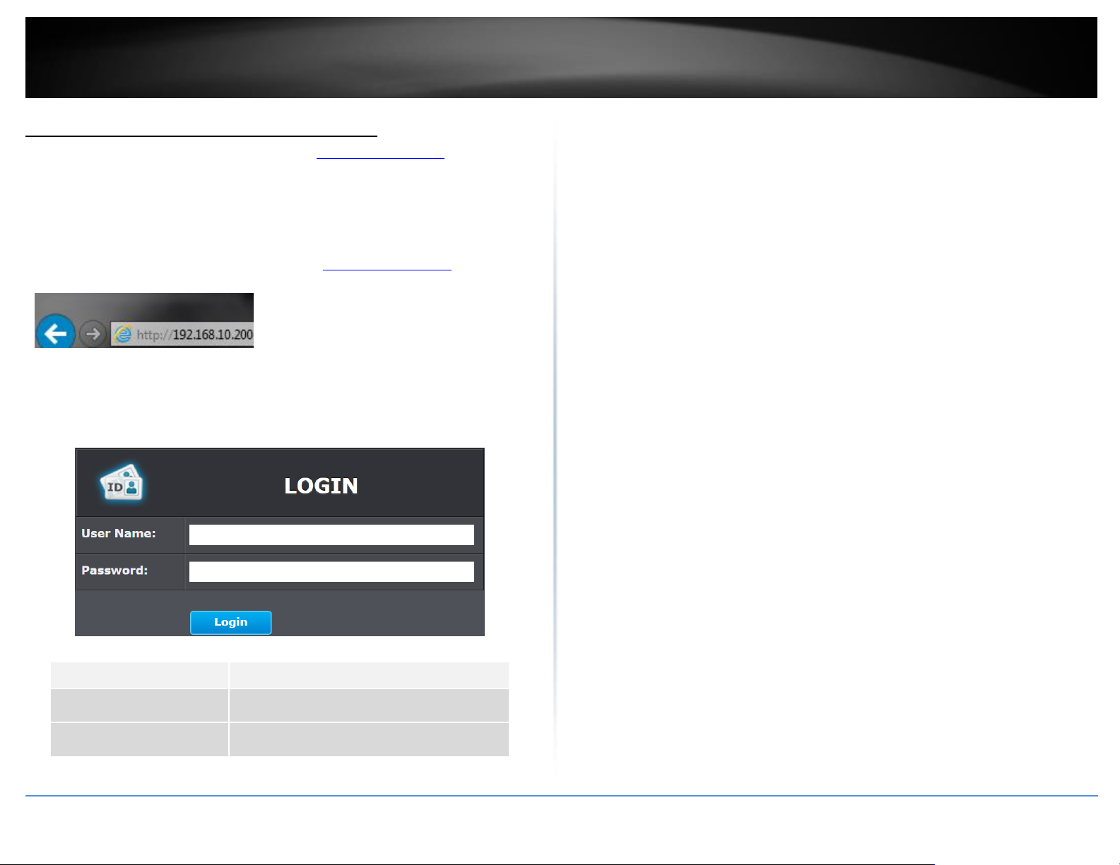
3. Open your web browser, and type the IP address of the switch in the address bar, and
then press Enter. The default IP address is 192.168.10.200.
4. Enter the User Name and Password, and then click Login. By default:
User Name: admin
Password: admin
Note: User name and password are case sensitive.
5. Click Basic Settings and then click General Settings.
6. Configure the switch IP address settings to be within your network subnet, then click
Apply.
Note: You may need to modify the static IP address settings of your computer’s network
adapter to IP address settings within your subnet in order to regain access to the switch
.
7. Click Save at the top right.
8. When confirmation message appears click OK.
Note: Once the settings are saved, you can connect the switch to your network.
© Copyright 2019 TRENDnet. All Rights Reserved.
Page 18
15
TRENDnet User’s Guide
Industrial Managed Switch Series
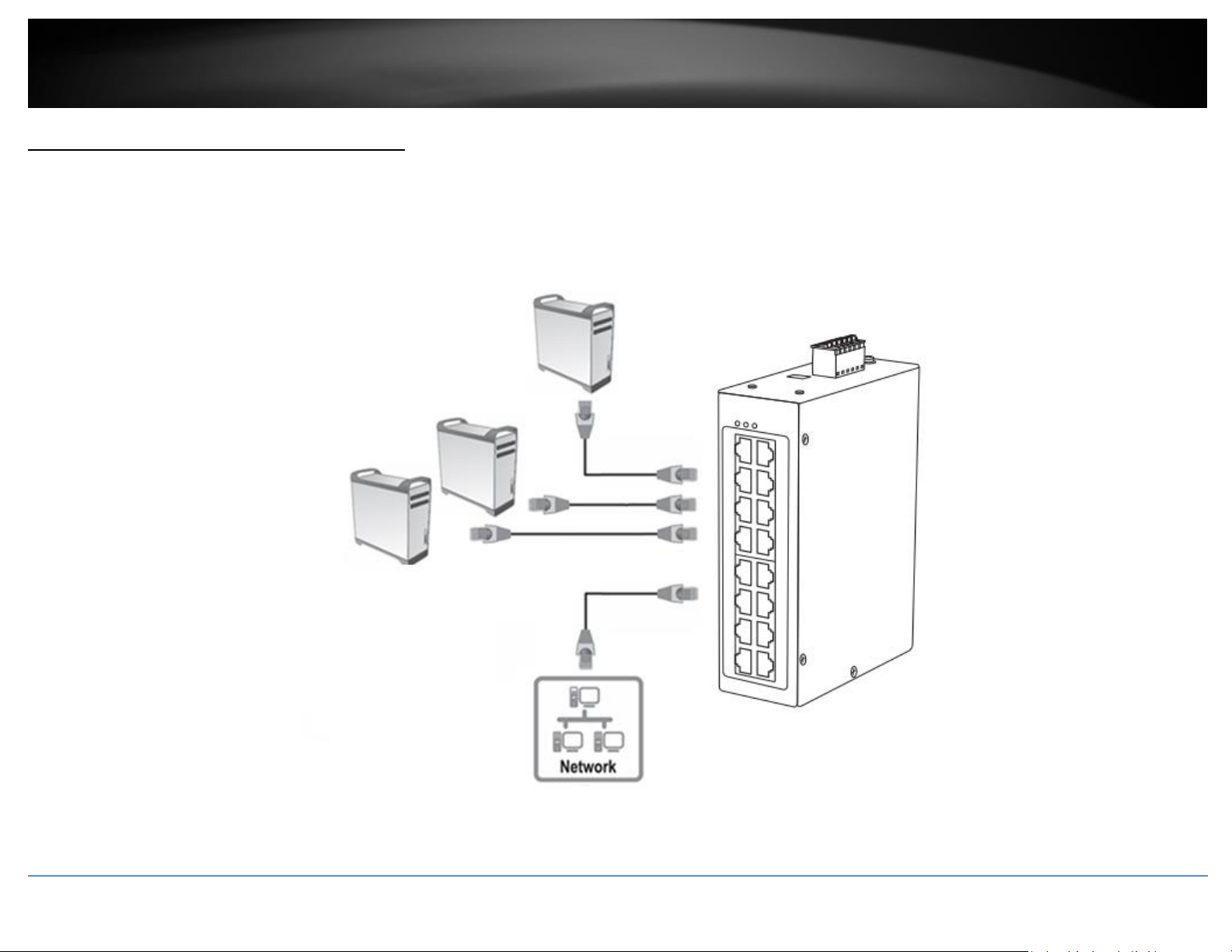
Connect additional devices to your switch
You can connect additional computers or other network devices to your switch using Ethernet cables to connect them to one of the available Gigabit Ports. Check the status of the LED
indicators on the front panel of your switch to ensure the physical cable connection from your computer or device.
Note: If you encounter issues connecting to your network, there may be a problem with your computer or device network settings. Please ensure that your computer or device network
settings (also called TCP/IP settings) are configured properly within the network subnet your switch is connected.
© Copyright 2019 TRENDnet. All Rights Reserved.
Page 19
TRENDnet User’s Guide
Industrial Managed Switch Series
16
Setting
Default Value
Default Username
admin
Default Password
admin
Setting
Default Value
IP Address
192.168.10.200
Subnet Mask
255.255.255.0
Default Gateway
0.0.0.0
Management VLAN
1
Default Username
admin
Default Password
admin
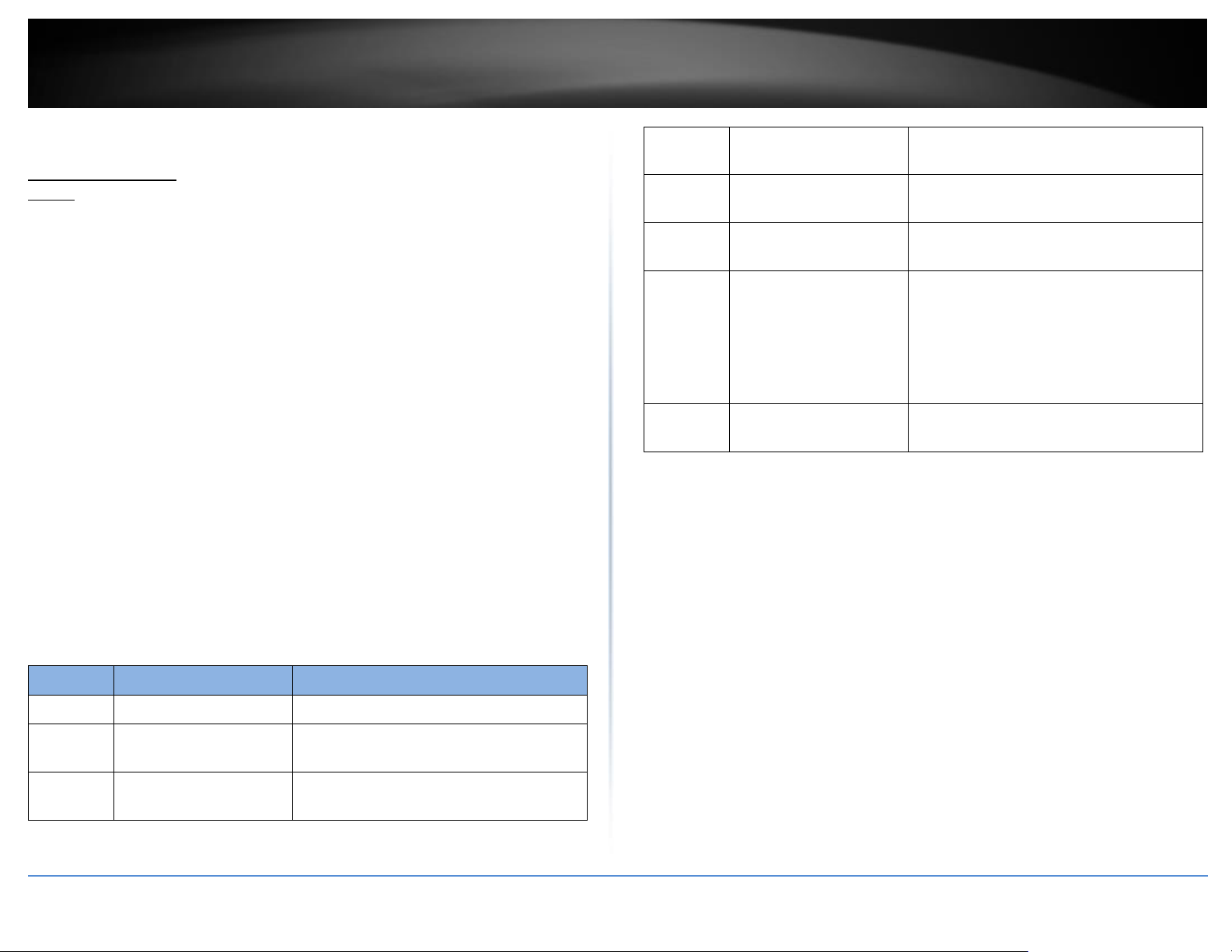
Node
Command
Description
enable
show hostname
This command displays the system’s network
name.
configure
reboot
This command reboots the system.
eth0
ip address A.B.C.D/M
This command configures a static IP and subnet
mask for the system.
interface
show
This command displays the current port
configurations.
vlan
show
This command displays the current VLAN
configurations.
Accessing switch management interfaces
Access your switch command line interface
Note: The system may be managed using the Telnet protocol. The Telnet protocol is
enabled by default. Throughout this user’s guide, the term “CLI Configuration” will be
used reference access through the command line interface.
1. Connect your computer to one of the available Ethernet ports and make sure your
computer and switch are assigned to an IP address with the same IP subnet.
2. On your computer, run the terminal emulation program (ex. HyperTerminal,
TeraTerm, Putty, etc.) and set the program to use the Telnet protocol and enter the IP
address assigned to the switch. The default IP address of the switch is 192.168.10.200
/ 255.255.255.0.
3. The terminal emulation window should display a prompt for user name and
password.
Enter the user name and password. By default:
Console User Name: admin
Note: User Name and Password are case sensitive.
Enable Mode/Privileged Exec User Name: admin
Enable Mode/Privileged Exec Password: admin
© Copyright 2019 TRENDnet. All Rights Reserved.
CLI Command Modes
Page 20

TRENDnet User’s Guide
Industrial Managed Switch Series
17
The Node type:
enable
Its command prompt is “[DEVICE_NAME]#”.
It means these commands can be executed in this command prompt.
configure
Its command prompt is “[DEVICE_NAME](config)#”.
It means these commands can be executed in this command prompt.
In Enable code, executing command “configure terminal” enter the configure
node.
[DEVICE_NAME]# configure terminal
eth0
Its command prompt is “[DEVICE_NAME](config-if)#”.
It means these commands can be executed in this command prompt.
In Configure code, executing command “interface eth0” enter the eth0
interface node.
[DEVICE_NAME](config)#interface eth0
[DEVICE_NAME](config-if)#
interface
Its command prompt is “[DEVICE_NAME](config-if)#”.
It means these commands can be executed in this command prompt.
In Configure code, executing command “interface gigaethernet1/0/5” enter
the interface port 5 node.
Or
In Configure code, executing command “interface fastethernet1/0/5” enter
the interface port 5 node.
Note: depend on your port speed, gigaethernet1/0/5 for gigabit Ethernet
ports and fastethernet1/0/5 for fast Ethernet ports.
[DEVICE_NAME](config)#interface gigaethernet1/0/5
[DEVICE_NAME](config-if)#
vlan
Its command prompt is “[DEVICE_NAME](config-vlan)#”.
It means these commands can be executed in this command prompt.
In Configure code, executing command “vlan 2” enter the vlan 2 node.
Note: where the “2” is the vlan ID.
[DEVICE_NAME](config)#vlan 2
[DEVICE_NAME](config-vlan)#
© Copyright 2019 TRENDnet. All Rights Reserved.
Page 21
TRENDnet User’s Guide
Industrial Managed Switch Series
18
Parameter
Description
User Name
Enter the user name.
Password
Enter the password.
Access your switch web management page
Note: Your switch default management IP address http://192.168.10.200 is accessed
through the use of your Internet web browser (e.g. Internet Explorer®, Firefox®,
Chrome™, Safari®, Opera™) and will be referenced frequently in this User’s Guide.
Throughout this user’s guide, the term Web Configuration will be used to reference
access from web management page.
1. Open your web browser and go to the IP address http://192.168.10.200. Your switch
will prompt you for a user name and password.
2. Enter the user name and password. By default:
User Name: admin
Password: admin
Note: User Name and Password are case sensitive.
© Copyright 2019 TRENDnet. All Rights Reserved.
Page 22
TRENDnet User’s Guide
Industrial Managed Switch Series
19
Node
Command
Description
enable
show hostname
This command displays the system’s network
name.
enable
show interface eth0
This command displays the current Eth0
configurations.
enable
show model
This command displays the system information.
enable
show running-config
This command displays the current operating
configurations.
enable
show system-info
This command displays the system’s CPU loading
and memory information.
enable
show uptime
This command displays the system up time.
Parameter
Description
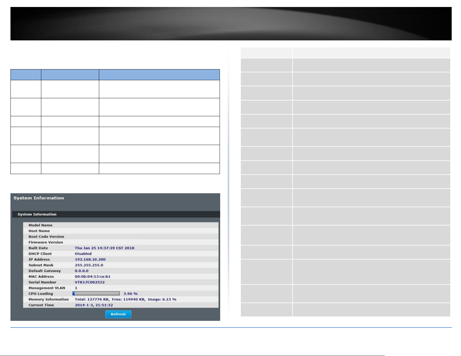
Model Name
This field displays the model name of the Switch.
Host Name
This field displays the name of the Switch.
Boot Code Version
This field displays the boot code version.
Firmware Version
This field displays the firmware version.
Built Date
This field displays the built date of the firmware.
DHCP Client
This field displays whether the DHCP client is enabled on the
Switch.
IP Address
This field indicates the IP address of the Switch.
Subnet Mask
This field indicates the subnet mask of the Switch.
Default Gateway
This field indicates the default gateway of the Switch.
MAC Address
This field displays the MAC (Media Access Control) address of the
Switch.
Serial Number
The serial number assigned by manufacture for identification of
the unit.
Management
VLAN
This field displays the VLAN ID that is used for the Switch
management purposes.
CPU Loading
This field displays the percentage of your Switch’s system load.
Memory
Information
This field displays the total memory the Switch has and the
memory which is currently available (Free) and occupied
(Usage).
Current Time
This field displays current date (yyyy-mm-dd) and time
(hh:mm:ss).
Refresh
Click this to update the information in this screen.
System Information
CLI Configuration
Web Configuration
System Status > System Information
© Copyright 2019 TRENDnet. All Rights Reserved.
Page 23
TRENDnet User’s Guide
Industrial Managed Switch Series
20
Node
Command
Description
configure
Reboot
This command reboots the system.
configure
hostname STRINGS
This command sets the system's network
name.
configure
interface eth0
This command enters the eth0 interface
node to configure the system IP.
eth0
Show
This command displays the eth0
configurations.
eth0
ip address A.B.C.D/M
This command configures a static IP and
subnet mask for the system.
eth0
ip address defaultgateway A.B.C.D
This command configures the system
default gateway.
eth0
ip dhcp client
(disable|enable|renew)
This command configures a DHCP client
function for the system.
Disable: Use a static IP address on the
switch.
Enable & Renew: Use DHCP client to get an
IP address from DHCP server.
eth0
management vlan
VLANID
This command configures the management
vlan.
Basic Settings
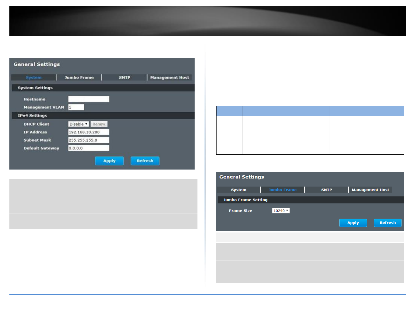
General Settings
System
Management VLAN
To specify a VLAN group which can access the Switch.
The valid VLAN range is from 1 to 4094.
If you want to configure a management VLAN, the management VLAN should
be created first and the management VLAN should have at least one member
port.
Host Name
The hostname is same as the SNMP system name. Its length is up to 64 characters.
The first 16 characters of the hostname will be configured as the CLI prompt.
Default Settings
The default Hostname is [YOUR_DEVICE_NAME]
The default DHCP client is disabled.
The default Static IP is 192.168.10.200
Subnet Mask is 255.255.255.0
Default Gateway is 0.0.0.0
Management VLAN is 1.
CLI Commands
© Copyright 2019 TRENDnet. All Rights Reserved.
Example: The procedures to configure an IP address for the Switch.
To enter the configure node.
[DEVICE_NAME]#configure terminal
[DEVICE_NAME](config)#
To enter the ETH0 interface node.
[DEVICE_NAME](config)#interface eth0
[DEVICE_NAME](config-if)#
To get an IP address from a DHCP server.
[DEVICE_NAME](config-if)#ip dhcp client enable
To configure a static IP address and a gateway for the Switch.
[DEVICE_NAME](config-if)#ip address 192.168.202.111/24
[DEVICE_NAME](config-if)#ip address default-gateway 192.168.202.1
Page 24
TRENDnet User’s Guide
Industrial Managed Switch Series
21
IP Address
Configures a IPv4 address for your Switch in dotted decimal
notation. For example, 192.168.10.200.
Subnet Mask
Enter the IP subnet mask of your Switch in dotted decimal
notation for example 255.255.255.0.
Default Gateway
Enter the IP address of the default outgoing gateway in dotted
decimal notation, for example 192.168.10.1.
Node
Command
Description
enable
show jumboframe
This command displays the
current jumbo frame settings.
configure
jumboframe
(10240|9216|1552|1536|1522)
This command configures the
maximum number of bytes of
frame size.
Parameter
Description
Frame Size
This field configures the maximum number of bytes of frame size
for specified port(s).
Apply
Click this button to take effect the settings.
Refresh
Click this button to reset the fields to the last setting.
Web Configuration
Basic Settings > General Settings > System
Notice:
The jumbo frame settings will apply to all ports.
If the size of a packet exceeds the jumbo frame size, the packet will be dropped.
The available values are 10240, 9216, 1552, 1536, 1522.
Default Settings
The default jumbo frame is 10240 bytes.
CLI Configuration
Web Configuration
Basic Settings > General Settings > Jumbo Frame
Jumbo Frame
Jumbo frames are Ethernet frames with a payload greater than 1500 bytes. Jumbo frames
can enhance data transmission efficiency in a network. The bigger the frame size, the
better the performance.
© Copyright 2019 TRENDnet. All Rights Reserved.
Page 25
TRENDnet User’s Guide
Industrial Managed Switch Series
22
Node
Command
Description
enable
show time
This command displays current time
and time configurations.
configure
time HOUR:MINUTE:SECOND
Sets the current time on the Switch.
hour: 0-23
min: 0-59
sec: 0-59
Note: If you configure Daylight Saving
Time
after you configure the time, the
Switch will apply Daylight Saving Time.
configure
time date YEAR/MONTH/DAY
Sets the current date on the Switch.
year: 1970-
month: 1-12
day: 1-31
configure
time daylight-saving-time
This command enables the daylight
saving time.
configure
time daylight-saving-time
start-date (first | second |
third | fourth | last) (Sunday
| Monday | Tuesday |
This command sets the start date for
the Daylight Saving Time.
For Example: first Sunday 4 0 (AM:0 1st
Sunday in April)
SNTP
The Network Time Protocol (NTP) is a protocol for synchronizing the clocks of computer
systems over packet-switched, variable-latency data networks. A less complex
implementation of NTP, using the same protocol but without requiring the storage of
state over extended periods of time is known as the Simple Network Time Protocol
(SNTP). NTP provides Coordinated Universal Time (UTC). No information about time
zones or daylight saving time is transmitted; this information is outside its scope and must
be obtained separately.
UDP Port: 123.
Daylight saving is a period from late spring to early fall when many countries set their
clocks ahead of normal local time by one hour to give more daytime light in the evening.
Note:
1. The SNTP server always replies the UTC current time.
2. When the Switch receives the SNTP reply time, the Switch will adjust the time
with the time zone configuration and then configure the time to the Switch.
3. If the time server’s IP address is not configured, the Switch will not send any
SNTP request packets.
4. If no SNTP reply packets, the Switch will retry every 10 seconds forever.
5. If the Switch has received SNTP reply, the Switch will re-get the time from NTP
server every 24 hours.
6. If the time zone and time NTP server have been changed, the Switch will
repeat the query process.
7. No default SNTP server.
Default Settings
Current Time:
---------------------------------------------- Time: 0:3:51 (UTC)
Date: 1970-1-1
Time Server Configuration:
-----------------------------------------------
© Copyright 2019 TRENDnet. All Rights Reserved.
Time Zone : +00:00
IP Address: 0.0.0.0
DayLight Saving Time Configuration:
---------------------------------------------- State : disabled
Start Date: None.
End Date : None.
CLI Configuration
Page 26
TRENDnet User’s Guide
Industrial Managed Switch Series
23
Wednesday | Thursday |
Friday | Saturday) MONTH
OCLOCK
configure
time daylight-saving-time
end-date (first | second |
third | fourth | last) (Sunday
| Monday | Tuesday |
Wednesday | Thursday |
Friday | Saturday) MONTH
OCLOCK
This command sets the end date for
the Daylight Saving Time.
For Example: Last Sunday 10 18 (PM: 6
Last Sunday in October)
configure
no time daylight-saving-time
This command disables daylight saving
on the Switch.
configure
time ntp-server IP_ADDRESS
This command sets the IP address of
your time server.
configure
no time ntp-server
This command disables the NTP server
settings.
configure
time timezone VALUE
Selects the time difference between
UTC (formerly known as GMT) and your
time zone.
Valid value: -1200 to 1200.
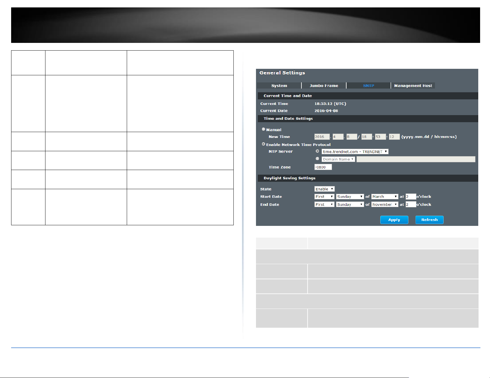
Parameter
Description
Current Time and Date
Current Time
This field displays the time you open / refresh this menu.
Current Date
This field displays the date you open / refresh this menu.
Time and Date Setting
Manual
Select this option if you want to enter the system date and time
manually.
Web Configuration
Basic Settings > General Settings > SNTP
Example:
[DEVICE_NAME](config)#time ntp-server 192.5.41.41
[DEVICE_NAME](config)#time timezone +0800
[DEVICE_NAME](config)#time ntp-server enable
[DEVICE_NAME](config)#time daylight-saving-time start-date first Monday 6 0
[DEVICE_NAME](config)#time daylight-saving-time end-date last Saturday 10 0
© Copyright 2019 TRENDnet. All Rights Reserved.
Page 27
TRENDnet User’s Guide
Industrial Managed Switch Series
24
New Time
Enter the new date in year, month and day format and time in
hour, minute and second format. The new date and time then
appear in the Current Date and Current Time fields after you click
Apply.
Enable
Network Time
Protocol
Select this option to use Network Time Protocol (NTP) for the time
service.
NTP Server
Select a pre-designated time server or type the IP address or type
the domain name of your time server. The Switch searches for the
timeserver for up to 60 seconds.
Time Zone
Select the time difference between UTC (Universal Time
Coordinated, formerly known as GMT, Greenwich Mean Time)
and your time zone from the drop-down list box.
Daylight Saving Settings
State
Select Enable if you want to use Daylight Saving Time. Otherwise,
select Disable to turn it off.
Start Date
Configure the day and time when Daylight Saving Time starts if you
enabled Daylight Saving Time. The time is displayed in the 24 hour
format. Here are a couple of examples:
Daylight Saving Time starts in most parts of the United States on
the second Sunday of March. Each time zone in the United States
starts using Daylight Saving Time at 2 A.M. local time. So in the
United States you would select Second, Sunday, March and 2:00.
Daylight Saving Time starts in the European Union on the last
Sunday of March. All of the time zones in the European Union start
using Daylight Saving Time at the same moment (1 A.M. GMT or
UTC). So in the European Union you would select Last, Sunday,
March and the last field depends on your time zone. In Germany
for instance, you would select 2:00 because Germany's time zone
is one hour ahead of GMT or UTC (GMT+1).
End Date
Configure the day and time when Daylight Saving Time ends if you
enabled Daylight Saving Time. The time field uses the 24 hour
format.
Here are a couple of examples:
Daylight Saving Time ends in the United States on the last Sunday
of October. Each time zone in the United States stops using
Daylight Saving Time at 2 A.M. local time. So in the United States
you would select First, Sunday, November and 2:00.
Daylight Saving Time ends in the European Union on the last
Sunday of October. All of the time zones in the European Union
stop using Daylight Saving Time at the same moment (1 A.M. GMT
or UTC). So in the European Union you would select Last, Sunday,
October and the last field depends on your time zone. In Germany
for instance, you would select 2:00 because Germany's time zone
is one hour ahead of GMT or UTC (GMT+1).
Apply
Click Apply to take effect the settings.
Refresh
Click Refresh to begin configuring this screen afresh.
Node
Command
Description
enable
show interface eth0
The command displays the all of the interface
eth0 configurations.
eth0
show
The command displays the all of the interface
eth0 configurations.
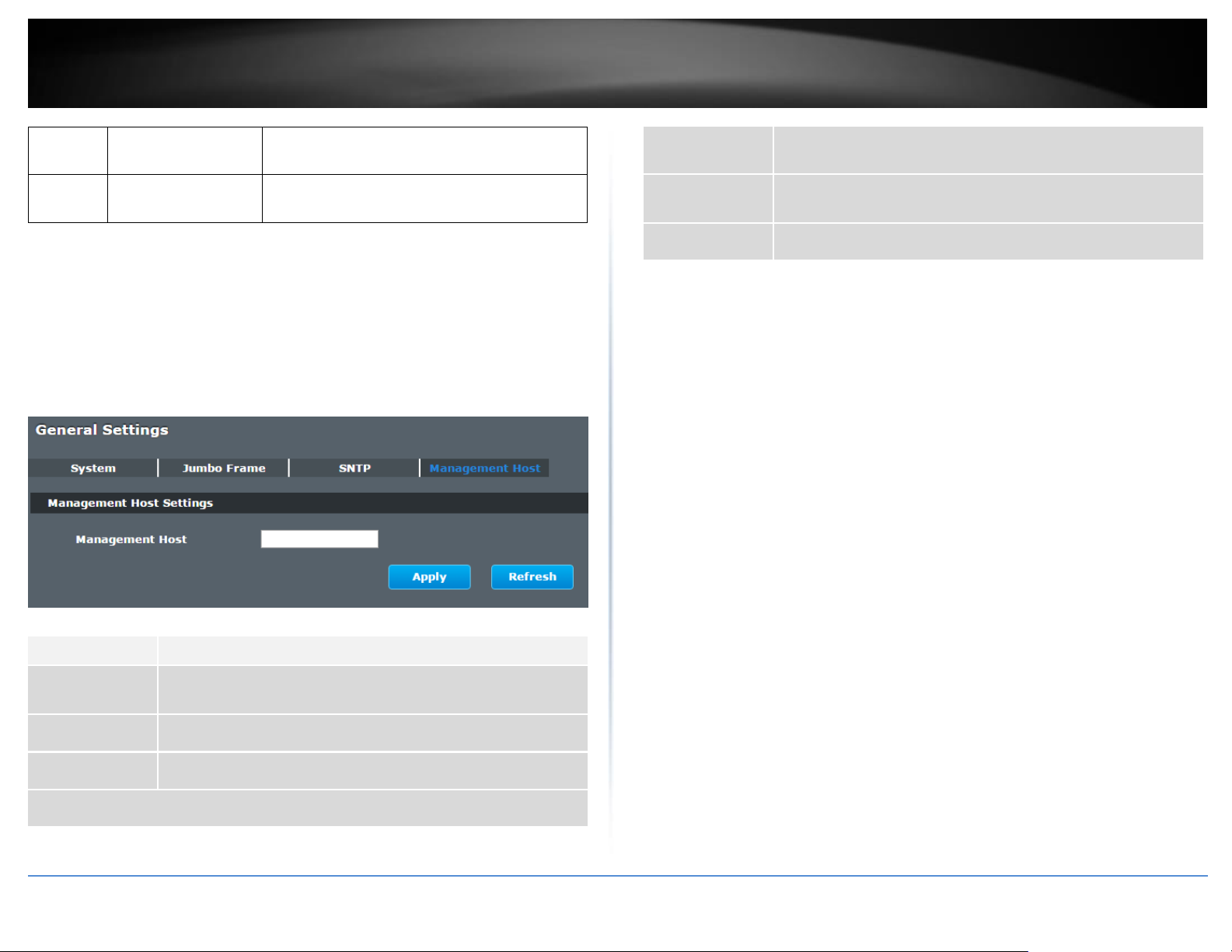
Management Host
The feature limits the hosts which can manage the Switch. That is, any hosts can manage
the Switch via telnet or web browser. If user has configured one or more management
host, the Switch can be managed by these hosts only. The feature allow user to configure
management IP up to 3 entries.
© Copyright 2019 TRENDnet. All Rights Reserved.
Default Settings
The default is none, any host can manage the Switch via telnet or web browser.
CLI Configuration
Page 28
TRENDnet User’s Guide
Industrial Managed Switch Series
25
eth0
management host
A.B.C.D
The command adds a management host address.
eth0
no management host
A.B.C.D
The command deletes a management host
address.
Parameter
Description
Management
Host
This field configures the management host.
Apply
Click this button to take effect the settings.
Refresh
Click this button to begin configuring this screen afresh.
Management Host List
No.
This field displays a sequential number for each management
host.
Management
Host
This field displays the management host.
Action
Click the Delete button to remove the specified entry.
Example:
[DEVICE_NAME]#configure terminal
[DEVICE_NAME](config)#interface eth0
[DEVICE_NAME](config-if)#management host 192.168.200.106
Web Configuration
Basic Settings > General Settings > Management Host
© Copyright 2019 TRENDnet. All Rights Reserved.
Page 29
TRENDnet User’s Guide
Industrial Managed Switch Series
26
Node
Command
Description
enable
show mac-addresstable aging-time
This command displays the current MAC
address table age time.
enable
show mac-addresstable (static|dynamic)
This command displays the current
static/dynamic unicast address entries.
enable
show mac-addresstable mac MACADDR
This command displays information of a
specific MAC.
enable
show mac-addresstable port PORT_ID
This command displays the current unicast
address entries learnt by the specific port.
configure
mac-address-table
static MACADDR vlan
VLANID port PORT_ID
This command configures a static unicast
entry.
configure
no mac-address-table
This command removes a static unicast entry
MAC Management
Dynamic Address:
The MAC addresses are learnt by the switch. When the switch receives frames, it will
record the source MAC, the received port and the VLAN in the address table with an age
time. When the age time is expired, the address entry will be removed from the address
table.
Static Address:
The MAC addresses are configured by users. The static addresses will not be aged out by
the switch; it can be removed by user only. The maximum static address entry is up to
256.
The MAC Table (a MAC table is also known as a filtering database) shows how frames are
forwarded or filtered across the Switch’s ports. When a device (which may belong to a
VLAN group) sends a packet which is forwarded to a port on the Switch, the MAC address
of the device is shown on the Switch’s MAC Table. It also shows whether the MAC address
is dynamic (learned by the Switch) or static (manually entered).
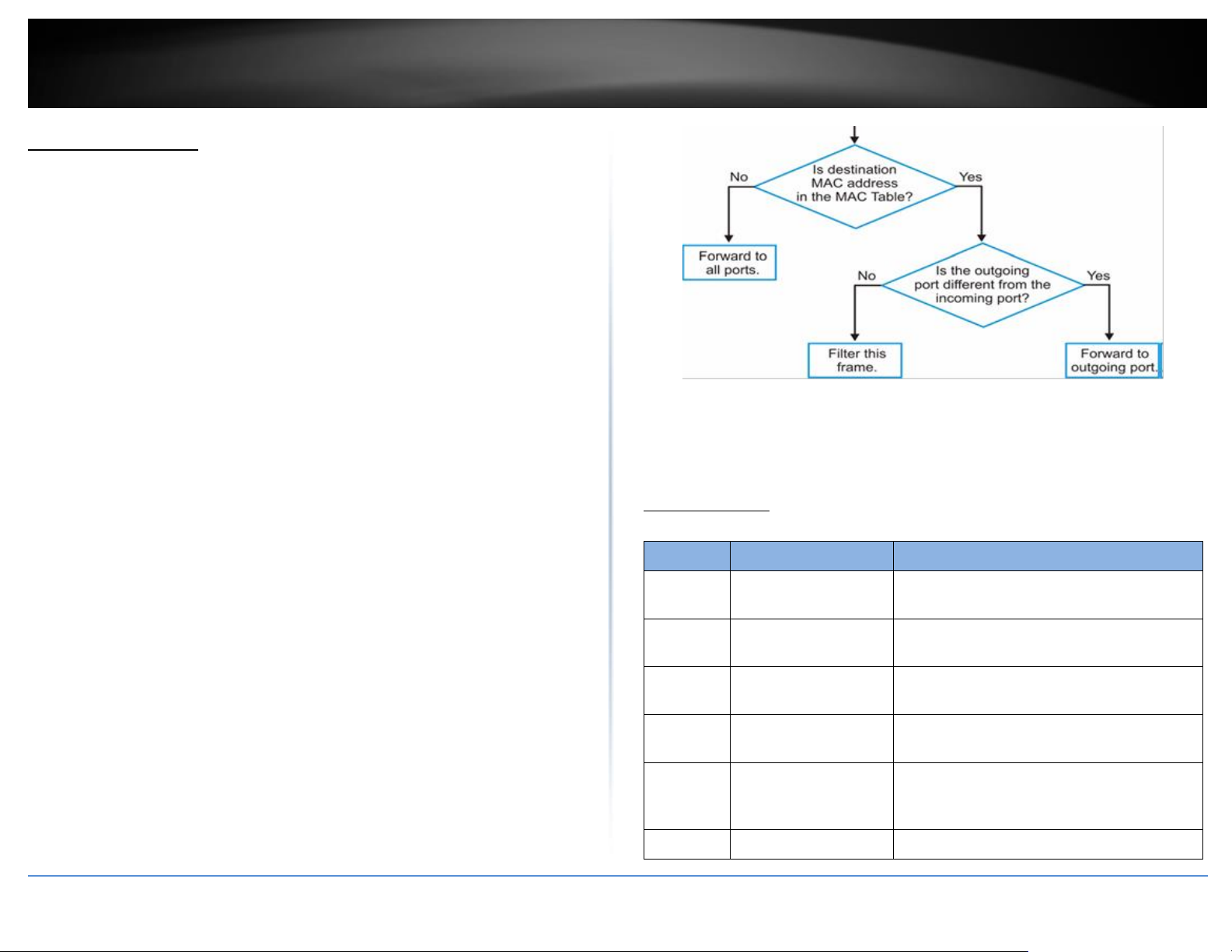
The Switch uses the MAC Table to determine how to forward frames. See the following
figure.
1. The Switch examines the received frame and learns the port from which this
source MAC address came.
2. The Switch checks to see if the frame's destination MAC address matches a
source MAC address already learnt in the MAC Table.
If the Switch has already learnt the port for this MAC address, then it
forwards the frame to that port.
If the Switch has not already learnt the port for this MAC address, then
the frame is flooded to all ports. If too much port flooding, it may lead
to network congestion.
If the Switch has already learnt the port for this MAC address, but the
destination port is the same as the port it came in on, then it filters the
frame.
Default Settings
The default MAC address table age time is 300 seconds.
The Maximum static address entry is 256.
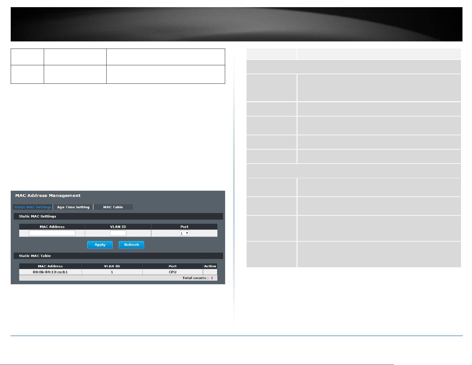
Static MAC Settings
CLI Configuration
Figure MAC Table Flowchart
© Copyright 2019 TRENDnet. All Rights Reserved.
Page 30
TRENDnet User’s Guide
Industrial Managed Switch Series
27
static MACADDR vlan
VLANID
from the address table.
configure
clear mac addresstable dynamic
This command clears the dynamic address
entries.
Parameter
Description
Static MAC Settings
MAC Address
Enter the MAC address of a computer or device that you want to
add to the MAC address table.
Valid format is hh:hh:hh:hh:hh:hh.
VLAN ID
Enter the VLAN ID to apply to the computer or device.
Port
Enter the port number to which the computer or device is
connected.
Apply
Click Apply to take effect the settings.
Refresh
Click Refresh to begin configuring this screen afresh.
Static MAC Table
MAC Address
This field displays the MAC address of a manually entered MAC
address entry.
VLAN ID
This field displays the VID of a manually entered MAC address
entry.
Port
This field displays the port number of a manually entered MAC
address entry. The MAC address with port CPU means the
Switch’s MAC addresses itself.
Action
Click Delete to remove this manually entered MAC address entry
from the MAC address table. You cannot delete the Switch’s MAC
address from the static MAC address table.
Example:
[DEVICE_NAME](config)#mac-address-table static 00:11:22:33:44:55 vlan 1 port 1
Web Configuration
Basic Settings > MAC Management > Static MAC Settings
Static MAC
A static Media Access Control (MAC) address is an address that has been manually
entered in the MAC address table, and do not age out. When you set up static MAC
address rules, you are setting static MAC addresses for a port, so this may reduce the
need for broadcasting.
© Copyright 2019 TRENDnet. All Rights Reserved.
Page 31

TRENDnet User’s Guide
Industrial Managed Switch Series
28
Parameter
Description
Age Time
Configure the age time; the valid range is from 20 to 500 seconds. The
default value is 300 seconds.
Apply
Click Apply to take effect the settings.
Refresh
Click this to update the information in the MAC table.
Parameter
Description
Show Type
Apply
Select All, Static, Dynamic or Port and then click Apply to display
the corresponding MAC address entries on this screen.
Refresh
Click this to update the information in the MAC table.
MAC Address
This field displays a MAC address.
Type
This field displays whether this entry was entered manually
(Static) or whether it was learned by the Switch (Dynamic).
VLAN ID
This field displays the VLAN ID of the MAC address entry.
Port
This field displays the port number the MAC address entry is
associated. It displays CPU if it is the entry for the Switch itself.
The CPU means that it is the Switch’s MAC.
Total Counts
This field displays the total entries in the MAC table.
Age Time Settings
Basic Settings > MAC Management > Age Time Settings
MAC Table
Basic Settings > MAC Management > MAC Table
© Copyright 2019 TRENDnet. All Rights Reserved.
Page 32

TRENDnet User’s Guide
Industrial Managed Switch Series
29
Node
Command
Description
enable
show mirror
This command displays the current port
mirroring configurations.
configure
mirror (disable|enable)
This command disables / enables the port
mirroring on the switch.
configure
mirror destination port
PORT_ID
This command specifies the monitor port for
the port mirroring.
configure
mirror source ports
PORT_LIST mode
(both|ingress|egress)
This command adds a port or a range of ports
as the source ports of the port mirroring.
configure
no mirror source ports
PORT_LIST
This command removes a port or a range of
ports from the source ports of the port
mirroring.
Port Mirror
Port-based Mirroring
The Port-Based Mirroring is used on a network switch to send a copy of network packets
sent/received on one or a range of switch ports to a network monitoring connection on
another switch port (Monitor to Port). This is commonly used for network appliances that
require monitoring of network traffic, such as an intrusion-detection system.
Port Mirroring, together with a network traffic analyzer, helps to monitor network traffic.
Users can monitor the selected ports (Source Ports) for egress and/or ingress packets.
Source Mode:
Ingress : The received packets will be copied to the monitor port.
Egress : The transmitted packets will be copied to the monitor port.
Both : The received and transmitted packets will be copied to the monitor
port.
Note:
1. The monitor port cannot be a trunk member port.
2. The monitor port cannot be ingress or egress port.
3. If the Port Mirror function is enabled, the Monitor-to Port can receive mirrored
packets only.
4. If a port has been configured as a source port and then user configures the port
as a destination port, the port will be removed from the source ports
automatically.
Default Settings
Mirror Configurations:
State : Disable
Monitor port : 1
Ingress port(s) : None
Egress port(s) : None
CLI Configuration
Example:
[DEVICE_NAME]#configure terminal
[DEVICE_NAME](config)#mirror enable
[DEVICE_NAME](config)#mirror destination port 2
[DEVICE_NAME](config)#mirror source ports 3-5 mode both
© Copyright 2019 TRENDnet. All Rights Reserved.
Page 33

TRENDnet User’s Guide
Industrial Managed Switch Series
30
Parameter
Description
State
Select Enable to turn on port mirroring or select Disable to turn it
off.
Monitor to Port
Select the port which connects to a network traffic analyzer.
All Ports
Settings in this field apply to all ports.
Use this field only if you want to make some settings the same
for all ports.
Use this field first to set the common settings and then make
adjustments on a port-by-port basis.
Source Port
This field displays the number of a port.
Mirror Mode
Select Ingress, Egress or Both to only copy the ingress (incoming),
egress (outgoing) or both (incoming and outgoing) traffic from the
specified source ports to the monitor port. Select Disable to not
copy any traffic from the specified source ports to the monitor
port.
Apply
Click Apply to take effect the settings.
Refresh
Click Refresh to begin configuring this screen afresh.
Web Configuration
Basic Settings > Port Mirroring
© Copyright 2019 TRENDnet. All Rights Reserved.
Page 34

TRENDnet User’s Guide
Industrial Managed Switch Series
31
Port Settings
Duplex mode
A duplex communication system is a system composed of two connected parties or
devices that can communicate with one another in both directions.
Half Duplex:
A half-duplex system provides for communication in both directions, but only one
direction at a time (not simultaneously). Typically, once a party begins receiving a signal,
it must wait for the transmitter to stop transmitting, before replying.
Full Duplex:
A full-duplex, or sometimes double-duplex system, allows communication in both
directions, and, unlike half-duplex, allows this to happen simultaneously. Land-line
telephone networks are full-duplex, since they allow both callers to speak and be heard
at the same time.
Loopback Test
A loopback test is a test in which a signal in sent from a communications device and
returned (looped back) to it as a way to determine whether the device is working right or
as a way to pin down a failing node in a network. One type of loopback test is performed
using a special plug, called a wrap plug that is inserted in a port on a communications
device. The effect of a wrap plug is to cause transmitted (output) data to be returned as
received (input) data, simulating a complete communications circuit using a single
computer.
Auto MDI-MDIX
Auto-MDIX (automatic medium-dependent interface crossover) is a computer
networking technology that automatically detects the required cable connection type
(straight-through or crossover) and configures the connection appropriately, thereby
removing the need for crossover cables to interconnect switches or connecting PCs peerto-peer. When it is enabled, either type of cable can be used or the interface
automatically corrects any incorrect cabling. For Auto-MDIX to operate correctly, the
speed on the interface and duplex setting must be set to "auto". Auto-MDIX was
developed by HP engineers Dan Dove and Bruce Melvin.
Auto Negotiation
Auto (auto-negotiation) allows one port to negotiate with a peer port automatically to
obtain the connection speed and duplex mode that both ends support. When autonegotiation is turned on, a port on the Switch negotiates with the peer automatically to
determine the connection speed and duplex mode.
If the peer port does not support auto-negotiation or turns off this feature, the Switch
determines the connection speed by detecting the signal on the cable and using half
duplex mode. When the Switch’s auto-negotiation is turned off, a port uses the pre-
configured speed and duplex mode when making a connection, thus requiring you to
make sure that the settings of the peer port are the same in order to connect.
Flow Control
A concentration of traffic on a port decreases port bandwidth and overflows buffer
memory causing packet discards and frame losses.IEEE802.3x flow control is used in full
duplex mode to send a pause signal to the sending port, causing it to temporarily stop
sending signals when the receiving port memory buffers fill and resend later.
© Copyright 2019 TRENDnet. All Rights Reserved.
Page 35

TRENDnet User’s Guide
Industrial Managed Switch Series
32
Node
Command
Description
enable
show interface IFNAME
This command displays the current
port configurations.
configure
interface IFNAME
This command enters the interface
configure node.
interface
show
This command displays the current
port configurations.
interface
loopback (none | mac)
This command tests the loopback
mode of operation for the specific
port.
interface
flowcontrol (off | on)
This command disables / enables
the flow control for the port.
interface
speed (auto|10-full||10-half|
100-full|100-half|1000-full)
This command configures the
speed and duplex for the port.
interface
shutdown
This command disables the specific
port.
interface
no shutdown
This command enables the specific
port.
interface
description STRINGs
This command configures a
description for the specific port.
interface
no description
This command configures the
default port description.
interface
cable test
This command diagnostics the
Ethernet cable and shows the
broken distance.
interface
clean cable-test result
This command cleans the test
result of the Ethernet cable test.
interface
show cable-test result
This command displays the test
result of the Ethernet cable test.
The Switch uses IEEE802.3x flow control in full duplex mode and backpressure flow
control in half duplex mode. IEEE802.3x flow control is used in full duplex mode to send
a pause signal to the sending port, causing it to temporarily stop sending signals when the
receiving port memory buffers fill. Back Pressure flow control is typically used in half
duplex mode to send a "collision" signal to the sending port (mimicking a state of packet
collision) causing the sending port to temporarily stop sending signals and resend later.
Note: 1000 Base-T doesn’t support force mode.
Cable Test.
This feature determines the quality of the cables, shorts, and cable impedance mismatch,
bad connectors, termination mismatch, and bad magnetics. The feature can work on the
copper Ethernet cable only.
Default Settings
The default port Speed & Duplex is auto for all ports.
The default port Flow Control is Off for all ports.
General Settings
CLI Configuration
© Copyright 2019 TRENDnet. All Rights Reserved.
Page 36

TRENDnet User’s Guide
Industrial Managed Switch Series
33
configure
interface range
gigabitethernet1/0/ PORTLISTS
This command enters the interface
configure node.
if-range
description STRINGs
This command configures a
description for the specific ports.
if-range
no description
This command configures the
default port description for the
specific ports.
if-range
shutdown
This command disables the specific
ports.
if-range
no shutdown
This command enables the specific
ports.
if-range
speed (auto|10-full||10-half|
100-full|100-half|1000-full)
This command configures the
speed and duplex for the port.
Parameter
Description
Port
Select a port or a range ports you want to configure on this screen.
State
Select Enable to activate the port or Disable to deactivate the port.
Speed/Duplex
Select the speed and duplex mode of the port. The choices are:
• Auto
• 10 Mbps / Full Duplex
• 10 Mbps / Half Duplex
• 100 Mbps / Full Duplex
• 100 Mbps / Half Duplex
• 1000 Mbps / Full Duplex
Flow Control
Select On to enable access to buffering resources for the port thus
ensuring lossless operation across network switches. Otherwise,
select Off to disable it.
Apply
Click Apply to take effect the settings.
Refresh
Click Refresh to begin configuring this screen afresh.
Port
This field displays the port number.
State
This field displays whether the port is enabled or disabled.
Speed/Duplex
This field displays the speed either 10M, 100M or 1000M and the
duplex mode Full or Half.
Flow Control
This field displays whether the port’s flow control is On or Off.
Link Status
This field displays the link status of the port. If the port is up, it
displays the port’s speed, duplex and flow control setting.
Otherwise, it displays Link Down if the port is disabled or not
connected to any device.
Example:
[DEVICE_NAME]#configure terminal
[DEVICE_NAME](config)#interface gi1/0/1
[DEVICE_NAME](config-if)#speed auto
Web Configuration
Basic Settings > Port Settings > General Settings
© Copyright 2019 TRENDnet. All Rights Reserved.
Page 37

TRENDnet User’s Guide
Industrial Managed Switch Series
34
Parameter
Description
Port
Select a port or a range ports you want to configure on this screen.
Description
Configures a meaningful name for the port(s).
Port Status
Port
This field displays the port number.
Description
The meaningful name for the port.
Status
The field displays the detail port status if the port is blocked by
some protocol.
Uptime
The sustained time from last link up.
Medium Mode
The current working medium mode, copper or fiber, for the port.
Information
Basic Settings > Port Settings > Information
© Copyright 2019 TRENDnet. All Rights Reserved.
Page 38

TRENDnet User’s Guide
Industrial Managed Switch Series
35
6
6 2 42-1496
4
DA
SA
Type / Length
Data
FCS
6
6
4 2 42-1496
4
DA
SA
802.1Q Tag
Type / Length
Data
FCS
Advanced Settings
Bandwidth Control
QoS
Each egress port can support up to 8 transmit queues. Each egress transmit queue
contains a list specifying the packet transmission order. Every incoming frame is
forwarded to one of the 8 egress transmit queues of the assigned egress port, based on
its priority. The egress port transmits packets from each of the 8 transmit queues
according to a configurable scheduling algorithm, which can be a combination of Strict
Priority (SP) and/or Weighted Round Robin (WRR).
Typically, networks operate on a best-effort delivery basis, which means that all traffic
has equal priority and an equal chance of being delivered in a timely manner. When
congestion occurs, all traffic has an equal chance of being dropped.
When you configure the QoS feature, you can select specific network traffic, prioritize it
according to its relative importance, and use congestion-management and congestionavoidance techniques to give preferential treatment. Implementing QoS in your network
makes network performance more predictable and bandwidth utilization more effective.
The Switch supports 802.1p priority queuing. The Switch has 8 priority queues. These
priority queues are numbered from 7 (Class 7) — the highest priority queue — to 0 (Class
0) — the lowest priority queue.
The eight priority tags specified in IEEE 802.1p (p0 to p7) are mapped to the Switch’s
priority queues as follows:
Priority : 0 1 2 3 4 5 6 7
Queue : 2 0 1 3 4 5 6 7
Priority scheduling is implemented by the priority queues stated above. The Switch will
empty the four hardware priority queues in order, beginning with the highest priority
queue, 7, to the lowest priority queue, 0. Each hardware queue will transmit all of the
packets in its buffer before permitting the next lower priority to transmit its packets.
When the lowest hardware priority queue has finished transmitting all of its packets, the
highest hardware priority queue will begin transmitting any packets it may have received.
QoS Enhancement
You can configure the Switch to prioritize traffic even if the incoming packets are not
marked with IEEE 802.1p priority tags or change the existing priority tags based on the
criteria you select. The Switch allows you to choose one of the following methods for
assigning priority to incoming packets on the Switch:
802.1p Tag Priority - Assign priority to packets based on the packet’s 802.1p
tagged priority.
Port Based QoS - Assign priority to packets based on the incoming port on the
Switch.
DSCP Based QoS - Assign priority to packets based on their Differentiated Services
Code Points (DSCPs).
Note: Advanced QoS methods only affect the internal priority queue mapping for the
Switch. The Switch does not modify the IEEE 802.1p value for the egress frames. You can
choose one of these ways to alter the way incoming packets are prioritized or you can
choose not to use any QoS enhancement setting on the Switch.
802.1p Priority
When using 802.1p priority mechanism, the packet is examined for the presence of a valid
802.1p priority tag. If the tag is present, the packet is assigned to a programmable egress
queue based on the value of the tagged priority. The tagged priority can be designated to
any of the available queues.
Ethernet Packet:
© Copyright 2019 TRENDnet. All Rights Reserved.
Page 39

TRENDnet User’s Guide
Industrial Managed Switch Series
36
2 bytes
2 bytes
Tag Protocol Identifier (TPID)
Tag Control Information (TCI)
16 bits
3 bits
1 bit
12 bits
TPID (0x8100)
Priority
CFI
VID
PCP
Network Priority
Traffic Characteristics
1
0 (lowest)
Background
0 1 Best Effort
2 2 Excellent Effort
3 3 Critical Applications
4 4 Video, <100ms latency
5 5 Video, < 10ms latency
6 6 Internetwork Control
7
7 (highest)
Network Control
Version
IHL
Type of Service
Total Length
Identification
Flags
Fragment Offset
Time to Live
Protocol
Header Checksum
Source Address
Destination Address
Options
Padding
802.1Q Tag:
Tag Protocol Identifier (TPID): a 16-bit field set to a value of 0x8100 in order to
identify the frame as an IEEE 802.1Q-tagged frame.
Tag Control Information (TCI)
Priority Code Point (PCP): a 3-bit field which refers to the IEEE 802.1p priority.
It indicates the frame priority level from 0 (lowest) to 7 (highest), which can
be used to prioritize different classes of traffic (voice, video, data, etc.).
Canonical Format Indicator (CFI): a 1-bit field. If the value of this field is 1, the
MAC address is in non-canonical format. If the value is 0, the MAC address is
in canonical format. It is always set to zero for Ethernet switches. CFI is used
for compatibility between Ethernet and Token Ring networks. If a frame
received at an Ethernet port has a CFI set to 1, then that frame should not be
bridged to an untagged port.
VLAN Identifier (VID): a 12-bit field specifying the VLAN to which the frame
belongs. A value of 0 means that the frame doesn't belong to any VLAN; in
this case the 802.1Q tag specifies only a priority and is referred to as a priority
tag. A value of hex 0xFFF is reserved for implementation use. All other values
may be used as VLAN identifiers, allowing up to 4094 VLANs. On bridges, VLAN
1 is often reserved for management.
Priority Levels
PCP: Priority Code Point.
DiffServ (DSCP)
Differentiated Services or DiffServ is a computer networking architecture that specifies a
simple, scalable and coarse-grained mechanism for classifying, managing network traffic
and providing Quality of Service (QoS) guarantees on modern IP networks. DiffServ can,
for example, be used to provide low-latency, guaranteed service (GS) to critical network
traffic such as voice or video while providing simple best-effort traffic guarantees to noncritical services such as web traffic or file transfers.
Differentiated Services Code Point (DSCP) is a 6-bit field in the header of IP packets for
packet classification purposes. DSCP replaces the outdated IP precedence, a 3-bit field in
the Type of Service byte of the IP header originally used to classify and prioritize types of
traffic.
When using the DiffServ priority mechanism, the packet is classified based on the DSCP
field in the IP header. If the tag is present, the packet is assigned to a programmable
egress queue based on the value of the tagged priority. The tagged priority can be
designated to any of the available queues.
Example Internet Datagram Header
© Copyright 2019 TRENDnet. All Rights Reserved.
Page 40

TRENDnet User’s Guide
Industrial Managed Switch Series
37
DSCP
Priority
DSCP
Priority
DSCP
Priority
0 0 1 0 2 0 60 0 31 0 62 0 63 0
IP Header Type of Service: 8 bits
The Type of Service provides an indication of the abstract parameters of the quality of
service desired. These parameters are to be used to guide the selection of the actual
service parameters when transmitting a datagram through a particular network. Several
networks offer service precedence, which somehow treats high precedence traffic as
more important than other traffic (generally by accepting only traffic above certain
precedence at time of high load). The major choice is a three way tradeoff between lowdelay, high-reliability, and high-throughput.
Bits 0-2: Precedence.
Bit 3: 0 = Normal Delay, 1 = Low Delay.
Bits 4: 0 = Normal Throughput, 1 = High Throughput.
Bits 5: 0 = Normal Reliability, 1 = High Reliability.
Bit 6-7: Reserved for Future Use.
0 1 2 3 4 5 6 7
+-----+-----+-----+-----+-----+-----+-----+-----+
| PRECEDENCE | D | T | R | 0 | 0 |
+-----+-----+-----+-----+-----+-----+-----+-----+
Precedence
111 - Network Control
110 - Internetwork Control
101 - CRITIC/ECP
100 - Flash Override
011 - Flash
010 - Immediate
001 - Priority
000 - Routine
The use of the Delay, Throughput, and Reliability indications may increase the cost (in
some sense) of the service. In many networks better performance for one of these
parameters is coupled with worse performance on another. Except for very unusual cases
at most two of these three indications should be set.
© Copyright 2019 TRENDnet. All Rights Reserved.
The type of service is used to specify the treatment of the datagram during its
transmission through the internet system. Example mappings of the internet type of
service to the actual service provided on networks such as AUTODIN II, ARPANET, SATNET,
and PRNET is given in "Service Mappings".
The Network Control precedence designation is intended to be used within a network
only. The actual use and control of that designation is up to each network. The
Internetwork Control designation is intended for use by gateway control originators only.
If the actual use of these precedence designations is of concern to a particular network,
it is the responsibility of that network to control the access to, and use of, those
precedence designations.
Example:
IP Header
DSCP=50 45 C8 . . .
Queuing Algorithms
Queuing algorithms allow switches to maintain separate queues for packets from each
individual source or flow and prevent a source from monopolizing the bandwidth.
Strict-Priority (SPQ)
The packets on the high priority queue are always service firstly.
Weighted round robin (WRR)
Page 41

TRENDnet User’s Guide
Industrial Managed Switch Series
38
Node
Command
Description
enable
show queue cos-map
This command displays the current 802.1p
priority mapping to the service queue.
enable
show qos mode
This command displays the current QoS
scheduling mode of IEEE 802.1p.
configure
queue cos-map
PRIORITY QUEUE_ID
This command configures the 802.1p priority
mapping to the service queue.
configure
no queue cos-map
This command configures the 802.1p priority
mapping to the service queue to default.
configure
qos mode high-first
This command configures the QoS scheduling
mode to high_first, each hardware queue will
transmit all of the packets in its buffer before
permitting the next lower priority to transmit
Round Robin scheduling services queues on a rotating basis and is activated only
when a port has more traffic than it can handle. A queue is given an amount of
bandwidth irrespective of the incoming traffic on that port. This queue then moves
to the back of the list. The next queue is given an equal amount of bandwidth, and
then moves to the end of the list; and so on, depending on the number of queues
being used. This works in a looping fashion until a queue is empty.
Weighted Round Robin (WRR) scheduling uses the same algorithm as round robin
scheduling, but services queues based on their priority and queue weight (the
number you configure in the queue Weight field) rather than a fixed amount of
bandwidth. WRR is activated only when a port has more traffic than it can handle.
Queues with larger weights get more service than queues with smaller weights. This
queuing mechanism is highly efficient in that it divides any available bandwidth
across the different traffic queues and returns to queues that have not yet emptied.
Default Settings
QoS mode : High First (SPQ)
The mappings of the Priority to Queue are:
PRIO 0 ==> COSQ 2
PRIO 1 ==> COSQ 0
PRIO 2 ==> COSQ 1
PRIO 3 ==> COSQ 3
PRIO 4 ==> COSQ 4
PRIO 5 ==> COSQ 5
PRIO 6 ==> COSQ 6
PRIO 7 ==> COSQ 7
The DiffServ is disabled on the switch.
DSCP Priority DSCP Priority DSCP Priority DSCP Priority
---- -------- ---- -------- ---- -------- ---- ------- 00 0 01 0 02 0 03 0
04 0 05 0 06 0 07 0
08 0 09 0 10 0 11 0
12 0 13 0 14 0 15 0
16 0 17 0 18 0 19 0
20 0 21 0 22 0 23 0
24 0 25 0 26 0 27 0
28 0 29 0 30 0 31 0
32 0 33 0 34 0 35 0
36 0 37 0 38 0 39 0
40 0 41 0 42 0 43 0
44 0 45 0 46 0 47 0
48 0 49 0 50 0 51 0
52 0 53 0 54 0 55 0
56 0 57 0 58 0 59 0
60 0 61 0 62 0 63 0
Note: If the DiffServ is disabled, the 802.1p tag priority will be used.
CLI Configuration
© Copyright 2019 TRENDnet. All Rights Reserved.
Page 42

TRENDnet User’s Guide
Industrial Managed Switch Series
39
its packets.
configure
qos mode wfq-queue
This command configures the QoS scheduling
mode to Weighted Fair Queuing.
configure
qos mode wrr-queue
weights VALUE VALUE
VALUE VALUE VALUE
VALUE VALUE VALUE
This command configures the QoS scheduling
mode to Weighted Round Robin.
interface
default-priority
This command allows the user to specify a
default priority handling of untagged packets
received by the Switch. The priority value
entered with this command will be used to
determine which of the hardware priority
queues the packet is forwarded to. Default: 0.
interface
no default-priority
This command configures the default priority
for the specific port to default (0).
enable
show diffserv
This command displays DiffServ
configurations.
configure
diffserv
(disable|enable)
This command disables / enables the DiffServ
function.
configure
diffserv dscp VALUE
priority VALUE
This command sets the DSCP-to-IEEE 802.1q
mappings.
Parameter
Description
All Ports 802.1p
priority
Use this field to set a priority for all ports.
The value indicates packet priority and is added to the priority tag
field of incoming packets. The values range from 0 (lowest
priority) to 7 (highest priority).
Port
This field displays the number of a port.
802.1p Priority
Select a priority for packets received by the port. Only packets
without 802.1p priority tagged will be applied the priority you set
here.
Web Configuration
Port Priority
Advanced Settings > Bandwidth Control > QoS
© Copyright 2019 TRENDnet. All Rights Reserved.
Page 43

TRENDnet User’s Guide
Industrial Managed Switch Series
40
Apply
Click Apply to take effect the settings.
Refresh
Click Refresh to begin configuring this screen afresh.
Parameter
Description
Mode
“Tag Over DSCP” or “DSCP Over Tag”. “Tag Over DSCP” means the 802.1p
tag has higher priority than DSCP.
Priority
This field displays each priority level. The values range from 0 (lowest
priority) to 7 (highest priority).
Apply
Click Apply to take effect the settings.
Refresh
Click Refresh to begin configuring this screen afresh.
Parameter
Description
Reset to Default
Click this button to reset the priority to queue mappings to the
defaults.
Priority
This field displays each priority level. The values range from 0
(lowest priority) to 7 (highest priority).
Queue ID
Select the number of a queue for packets with the priority level.
IP DiffServ (DSCP)
Advanced Settings > Bandwidth Control > IP DiffServ (DSCP)
Priority/Queue Mapping
Advanced Settings > Bandwidth Control > Priority/Queue Mapping
© Copyright 2019 TRENDnet. All Rights Reserved.
Page 44

TRENDnet User’s Guide
Industrial Managed Switch Series
41
Apply
Click Apply to take effect the settings.
Refresh
Click Refresh to begin configuring this screen afresh.
Parameter
Description
Schedule Mode
Select Strict Priority (SP) or Weighted Round Robin (WRR).
Note: Queue weights can only be changed when Weighted Round
Robin is selected.
Weighted Round Robin scheduling services queues on a rotating
basis based on their queue weight (the number you configure in
the queue Weight field). Queues with larger weights get more
service than queues with smaller weights.
Queue ID
This field indicates which Queue (0 to 7) you are configuring.
Queue 0 has the lowest priority and Queue 7 the highest priority.
Weight Value
You can only configure the queue weights when Weighted Round
Robin is selected. Bandwidth is divided across the different traffic
queues according to their weights.
Apply
Click Apply to take effect the settings.
Refresh
Click Refresh to begin configuring this screen afresh.
Schedule Mode
Advanced Settings > Bandwidth Control > Schedule
Rate Limitation
Storm Control
A broadcast storm means that your network is overwhelmed with constant broadcast or
multicast traffic. Broadcast storms can eventually lead to a complete loss of network
connectivity as the packets proliferate.
Storm Control protects the Switch bandwidth from flooding packets, including broadcast
packets, multicast packets, and destination lookup failure (DLF). The Rate is a threshold
that limits the total number of the selected type of packets. For example, if the broadcast
and multicast options are selected, the total amount of packets per second for those two
types will not exceed the limit value.
Broadcast storm control limits the number of broadcast, multicast and unknown unicast
© Copyright 2019 TRENDnet. All Rights Reserved.
(also referred to as Destination Lookup Failure or DLF) packets the Switch receives per
second on the ports. When the maximum number of allowable broadcast, multicast and
unknown unicast packets is reached per second, the subsequent packets are discarded.
Enable this feature to reduce broadcast, multicast and unknown unicast packets in your
network.
Storm Control unit : pps.
Default Settings
Broadcast Storm Control : 300pps.
Multicast Storm Control : None.
DLF Storm Control : 300pps.
Page 45

TRENDnet User’s Guide
Industrial Managed Switch Series
42
Node
Command
Description
enable
show storm-control
This command displays the current
storm control configurations.
configure
storm-control rate RATE_LIMIT
type (bcast | mcast | DLF |
bcast+mcast | bcast+DLF |
mcast+DLF | bcast+mcast+DLF)
ports PORTLISTS
This command enables the
bandwidth limit for broadcast or
multicast or DLF packets and set
the limitation.
configure
no storm-control type (bcast |
mcast | DLF | bcast+mcast |
bcast+DLF | mcast+DLF |
bcast+mcast+DLF) ports
PORTLISTS
This command disables the
bandwidth limit for broadcast or
multicast or DLF packets.
Parameter
Description
Port
Select the port number for which you want to configure storm control
settings.
Rate
Select the number of packets (of the type specified in the Type field) per
second the Switch can receive per second.
Type
Select Broadcast - to specify a limit for the amount of broadcast packets
received per second.
Multicast - to specify a limit for the amount of multicast packets
received per second.
DLF - to specify a limit for the amount of DLF packets received per
second.
Apply
Click Apply to take effect the settings.
Refresh
Click Refresh to begin configuring this screen afresh.
CLI Configuration
Example:
[DEVICE_NAME]#configure terminal
[DEVICE_NAME](config)#storm-control rate 1 type broadcast ports 1-6
[DEVICE_NAME](config)#storm-control rate 1 type multicast ports 1-6
[DEVICE_NAME](config)#storm-control rate 1 type DLF ports 1-6
Web Configuration
Advanced Settings > Bandwidth Control > Rate Limitation > Storm Control
© Copyright 2019 TRENDnet. All Rights Reserved.
Bandwidth Limitation
Page 46

TRENDnet User’s Guide
Industrial Managed Switch Series
43
Node
Command
Description
enable
show bandwidth-limit
This command displays the current rate
control configurations.
configure
bandwidth-limit egress
RATE_LIMIT ports
PORTLISTS
This command enables the bandwidth limit
for outgoing packets and set the limitation.
configure
no bandwidth-limit egress
ports PORTLISTS
This command disables the bandwidth limit
for outgoing packets.
configure
bandwidth-limit ingress
RATE_LIMIT ports
PORTLISTS
This command enables the bandwidth limit
for incoming packets and set the limitation.
configure
no bandwidth-limit
ingress ports PORTLISTS
This command disables the bandwidth limit
for incoming packets.
Parameter
Description
Port
Selects a port that you want to configure.
Ingress
Configures the rate limitation for the ingress packets.
Egress
Configures the rate limitation for the egress packets.
Apply
Click Apply to take effect the settings.
Refresh
Click Refresh to begin configuring this screen afresh.
The rate limitation is used to control the rate of traffic sent or received on a network
interface.
Rate Limitation unit: Mbs.
Default Settings
All ports’ Ingress and Egress rate limitation are disabled.
CLI Configuration
Web Configuration
Advanced Settings > Bandwidth Control > Rate Limitation > Bandwidth Limitation
Example:
[DEVICE_NAME]#configure terminal
[DEVICE_NAME](config)#bandwidth-limit egress 1 ports 1-6
[DEVICE_NAME](config)#bandwidth-limit ingress 1 ports 1-6
© Copyright 2019 TRENDnet. All Rights Reserved.
Page 47

TRENDnet User’s Guide
Industrial Managed Switch Series
44
IGMP Snooping
IGMP Snooping
The IGMP snooping is for multicast traffic. The Switch can passively snoop on IGMP
packets transferred between IP multicast routers/switches and IP multicast hosts to learn
the IP multicast group membership. It checks IGMP packets passing through it, picks out
the group registration information, and configures multicasting accordingly. IGMP
snooping allows the Switch to learn multicast groups without you having to manually
configure them.
The Switch can passively snoop on IGMP packets transferred between IP multicast
routers/switches and IP multicast hosts to learn the IP multicast group membership. It
checks IGMP packets passing through it, picks out the group registration information, and
configures multicasting accordingly. IGMP snooping allows the Switch to learn multicast
groups without you having to manually configure them.
The Switch forwards multicast traffic destined for multicast groups (that it has learned
from IGMP snooping or that you have manually configured) to ports that are members of
that group. IGMP snooping generates no additional network traffic, allowing you to
significantly reduce multicast traffic passing through your Switch.
The Switch can perform IGMP snooping on up to 4094 VLANs. You can configure the
Switch to automatically learn multicast group membership of any VLANs. The Switch then
performs IGMP snooping on the first VLANs that send IGMP packets. Alternatively, you
can specify the VLANs that IGMP snooping should be performed on. This is referred to as
fixed mode. In fixed mode the Switch does not learn multicast group membership of any
VLANs other than those explicitly added as an IGMP snooping VLAN.
Immediate Leave
When you enable IGMP Immediate-Leave processing, the switch
immediately removes a port when it detects an IGMP version 2 leave
message on that port. You should use the Immediate-Leave feature only
when there is a single receiver present on every port in the VLAN.
(Immediate Leave is only supported on IGMP Version 2 hosts).
The switch uses IGMP snooping Immediate Leave to remove from the forwarding table
an interface that sends a leave message without the switch sending group-specific queries
to the interface. The VLAN interface is pruned from the multicast tree for the multicast
group specified in the original leave message. Immediate Leave ensures optimal
bandwidth management for all hosts on a switched network, even when multiple
multicast groups are simultaneously in use.
Fast Leave
The switch allow user to configure a delay time. When the delay time is expired, the
switch removes the interface from the multicast group.
Last Member Query Interval
Last Member Query Interval: The Last Member Query Interval is the Max Response Time
inserted into Group-Specific Queries sent in response to Leave Group messages, and is
also the amount of time between Group-Specific Query messages.
Without Immediate Leave, when the switch receives an IGMP leave message from a
subscriber on a receiver port, it sends out an IGMP specific query on that port and waits
for IGMP group membership reports. If no reports are received in a configured time
period, the receiver port is removed from multicast group membership.
IGMP Querier
There is normally only one Querier per physical network. All multicast routers start up as
a Querier on each attached network. If a multicast router hears a Query message from a
router with a lower IP address, it MUST become a Non-Querier on that network. If a
router has not heard a Query message from another router for [Other Querier Present
Interval], it resumes the role of Querier. Routers periodically [Query Interval] send a
General Query on each attached network for which this router is the Querier, to solicit
membership information. On startup, a router SHOULD send [Startup Query Count]
General Queries spaced closely together [Startup Query Interval] in order to quickly and
reliably determine membership information. A General Query is addressed to the allsystems multicast group (224.0.0.1), has a Group Address field of 0, and has a Max
Response Time of [Query Response Interval].
© Copyright 2019 TRENDnet. All Rights Reserved.
Page 48

TRENDnet User’s Guide
Industrial Managed Switch Series
45
Node
Command
Description
enable
show igmp-snooping
This command displays the current IGMP
snooping configurations.
enable
show igmp-counters
This command displays the current IGMP
snooping counters.
enable
show igmp-counters
(port|vlan)
This command displays the current IGMP
snooping counters per port or per vlan.
configure
igmp-snooping (disable
| enable)
This command disables / enables the IGMP
snooping on the switch.
configure
igmp-snooping vlan
VLANID
This command enables the IGMP snooping
function on a VLAN or range of VLANs.
configure
no igmp-snooping vlan
VLANID
This command disables the IGMP snooping
function on a VLAN or range of VLANs.
configure
igmp-snooping
unknown-multicast
(drop|flooding)
This command configures the process for
unknown multicast packets when the IGMP
snooping function is enabled.
drop: Drop all of the unknown multicast
packets.
interface
igmp-querier-mode
(auto|fixed|edge)
This command specifies whether or not and
under what conditions the port(s) is (are)
IGMP query port(s). The Switch forwards
IGMP join or leave packets to an IGMP query
port, treating the port as being connected to
an IGMP multicast router (or server). You
must enable IGMP snooping as well.
Port IGMP Querier Mode
Auto:
The Switch uses the port as an IGMP query port if the port receives IGMP query
packets.
Fixed:
The Switch always treats the port(s) as IGMP query port(s). This is for when
connecting an IGMP multicast server to the port(s). The Switch always forwards the
client’s report/leave packets to the port.
Normally, the port is connected to an IGMP server.
Edge:
The Switch does not use the port as an IGMP query port. The IGMP query packets
received by this port will be dropped.
Normally, the port is connected to an IGMP client.
Note: The Switch will forward the IGMP join and leave packets to the query port.
Configurations:
Users can enable/disable the IGMP Snooping on the Switch. Users also can enable/disable
the IGMP Snooping on a specific VLAN. If the IGMP Snooping on the Switch is disabled,
the IGMP Snooping is disabled on all VLANs even some of the VLAN IGMP Snooping are
enabled.
Default Settings
If received packets are not received after 400 seconds, all multicast entries will be
deleted.
The default global IGMP snooping state is disabled.
The default VLAN IGMP snooping state is disabled for all VLANs.
The unknown multicast packets will be dropped.
The default port Immediate Leave state is disabled for all ports.
The default port Querier Mode state is auto for all ports.
The IGMP snooping Report Suppression is disabled.
© Copyright 2019 TRENDnet. All Rights Reserved.
Notices: There are a global state and per VLAN states. When the global state is disabled,
the IGMP snooping on the Switch is disabled even per VLAN states are enabled. When the
global state is enabled, user must enable per VLAN states to enable the IGMP Snooping
on the specific VLAN.
CLI Configuration
Page 49

TRENDnet User’s Guide
Industrial Managed Switch Series
46
(Default:auto)
interface
igmp-immediate-leave
This command enables the IGMP Snooping
immediate leave function for the specific
interface.
interface
no igmp-immediateleave
This command disables the IGMP Snooping
immediate leave function for the specific
interface.
Parameter
Description
IGMP Snooping
State
Select Enable to activate IGMP Snooping to forward group
multicast traffic only to ports that are members of that group.
Select Disable to deactivate the feature.
IGMP Snooping
VLAN State
Select Add and enter VLANs upon which the Switch is to perform
IGMP snooping. The valid range of VLAN IDs is between 1 and
4094. Use a comma (,) or hyphen (-) to specify more than one
VLANs. Select Delete and enter VLANs on which to have the
Switch not perform IGMP snooping.
Unknown
Multicast Packets
Specify the action to perform when the Switch receives an
unknown multicast frame. Select Drop to discard the frame(s).
Select Flooding to send the frame(s) to all ports.
Web Configuration
General Settings
Advanced Settings > IGMP Snooping > IGMP Snooping > General Settings
Example:
[DEVICE_NAME](config)#igmp-snooping enable
[DEVICE_NAME](config)#igmp-snooping vlan 1
[DEVICE_NAME](config)#interface 1/0/1
[DEVICE_NAME](config-if)#igmp-immediate-leave
[DEVICE_NAME](config-if)#igmp-querier-mode fixed
[DEVICE_NAME](config-if)#igmp-snooping group-limit 20
© Copyright 2019 TRENDnet. All Rights Reserved.
Page 50

TRENDnet User’s Guide
Industrial Managed Switch Series
47
Apply
Click Apply to configure the settings.
Refresh
Click this to reset the fields to the last setting.
IGMP Snooping
State
This field displays whether IGMP snooping is globally enabled or
disabled.
IGMP Snooping
VLAN State
This field displays VLANs on which the Switch is to perform IGMP
snooping. None displays if you have not enabled IGMP snooping
on any port yet.
Unknown
Multicast
Packets
This field displays whether the Switch is set to discard or flood
unknown multicast packets.
Parameter
Description
Querier Mode
Select the desired setting, Auto, Fixed, or Edge. Auto means
the Switch uses the port as an IGMP query port if the port
receives IGMP query packets. Fixed means the Switch always
treats the port(s) as IGMP query port(s). This is for when
connecting an IGMP multicast server to the port(s). Edge means
the Switch does not use the port as an IGMP query port. In this
case, the Switch does not keep a record of an IGMP router
being connected to this port and the Switch does not forward
IGMP join or leave packets to this port.
Immediate
Leave
Select individual ports on which to enable immediate leave.
Group Limit
Configures the maximum group for the port or a range of ports.
Apply
Click Apply to apply the settings.
Refresh
Click this to reset the fields.
Port
The port ID.
Querier Mode
The Querier mode setting for the specific port.
Immediate Leave
The Immediate Leave setting for the specific port.
Group Counts
The current joining group count and the maximum group count.
Port Settings
Advanced Settings > IGMP Snooping > IGMP Snooping > Port Settings
Multicast Address
A multicast address is associated with a group of interested receivers. According to RFC
3171, addresses 224.0.0.0 to 239.255.255.255, the former Class D addresses, are
designated as multicast addresses in IPv4.
The IANA owns the OUI MAC address 01:00:5e, therefore multicast packets are delivered
by using the Ethernet MAC address range 01:00:5e:00:00:00 - 01:00:5e:7f:ff:ff. This is 23
bits of available address space.
© Copyright 2019 TRENDnet. All Rights Reserved.
Page 51

TRENDnet User’s Guide
Industrial Managed Switch Series
48
Class
Address Range
Supports
Class A
1.0.0.1 to 126.255.255.254
Supports 16 million hosts on each of 127
networks.
Class B
128.1.0.1 to 191.255.255.254
Supports 65,000 hosts on each of 16,000
networks.
Class C
192.0.1.1 to 223.255.254.254
Supports 254 hosts on each of 2 million
networks.
Class D
224.0.0.0 to 239.255.255.255
Reserved for multicast groups.
Class E
240.0.0.0 to 254.255.255.254
Reserved for future use, or Research and
Development Purposes.
IP multicast
address
Description
224.0.0.0
Base address (reserved)
224.0.0.1
The All Hosts multicast group that contains all systems on the same
network segment
224.0.0.2
The All Routers multicast group that contains all routers on the same
network segment
224.0.0.5
The Open Shortest Path First (OSPF) AllSPFRouters address. Used to
send Hello packets to all OSPF routers on a network segment
224.0.0.6
The OSPF AllDRouters address. Used to send OSPF routing information
to OSPF designated routers on a network segment
The first octet (01) includes the broadcast/multicast bit. The lower 23 bits of the 28-bit
multicast IP address are mapped into the 23 bits of available Ethernet address space. This
means that there is ambiguity in delivering packets. If two hosts on the same subnet each
subscribe to a different multicast group whose address differs only in the first 5 bits,
Ethernet packets for both multicast groups will be delivered to both hosts, requiring the
network software in the hosts to discard the unrequired packets.
© Copyright 2019 TRENDnet. All Rights Reserved.
Page 52

TRENDnet User’s Guide
Industrial Managed Switch Series
49
224.0.0.9
The RIP version 2 group address, used to send routing information
using the RIP protocol to all RIP v2-aware routers on a network
segment
224.0.0.10
EIGRP group address. Used to send EIGRP routing information to all
EIGRP routers on a network segment
224.0.0.13
PIM Version 2 (Protocol Independent Multicast)
224.0.0.18
Virtual Router Redundancy Protocol
224.0.0.19 - 21
IS-IS over IP
224.0.0.22
IGMP Version 3 (Internet Group Management Protocol)
224.0.0.102
Hot Standby Router Protocol Version 2
224.0.0.251
Multicast DNS address
224.0.0.252
Link-local Multicast Name Resolution address
224.0.1.1
Network Time Protocol address
224.0.1.39
Cisco Auto-RP-Announce address
224.0.1.40
Cisco Auto-RP-Discovery address
224.0.1.41
H.323 Gatekeeper discovery address
Node
Command
Description
enable
show mac-address-table
multicast
This command displays the current
static/dynamic multicast address
entries.
configure
mac-address-table multicast
MACADDR vlan VLANID ports
PORTLIST
This command configures a static
multicast entry.
configure
no mac-address-table
multicast MACADDR
This command removes a static
multicast entry from the address table.
Parameter
Description
VLAN ID
Configures the VLAN that you want to configure.
MAC
Address
Configures the multicast MAC which will not be aged out.
Valid format is hh:hh:hh:hh:hh:hh.
Port
Configures the member port for the multicast address.
Apply
Click Apply to save your changes back to the Switch.
Refresh
Click Refresh to begin configuring this screen afresh.
Web Configuration
Advanced Settings > IGMP Snooping > Multicast Address
CLI Configuration
© Copyright 2019 TRENDnet. All Rights Reserved.
Page 53

TRENDnet User’s Guide
Industrial Managed Switch Series
50
Node
Command
Description
enable
show portisolation
This command displays the current port isolation
configurations.
“V” indicates the port’s packets can be sent
to that port.
“-” indicates the port’s packets cannot be
sent to that port.
interface
port-isolation
ports PORTLISTS
This command configures a port or a range of
ports to egress traffic from the specific port.
interface
no port-isolation
This command configures all ports to egress
traffic from the specific port.
VLAN
Port Isolation
The port isolation is a port-based virtual LAN feature. It partitions the switching ports into
virtual private domains designated on a per port basis. Data switching outside of the
port’s private domain is not allowed. It will ignore the packets’ tag VLAN information.
This feature is a per port setting to configure the egress port(s) for the specific port to
forward its received packets. If the CPU port (port 0) is not an egress port for a specific
port, the host connected to the specific port cannot manage the Switch.
If you wish to allow two subscriber ports to talk to each other, you must define the egress
port for both ports. CPU refers to the Switch management port. By default it forms a VLAN
with all Ethernet ports. If it does not form a VLAN with a particular port then the Switch
cannot be managed from that port.
Example: If you want to allow port-1 and port-3 to talk to each other, you must configure
as below:
[DEVICE_NAME](config)#interface 1/0/1
[DEVICE_NAME](config-if)#port-isolation ports 3
[DEVICE_NAME](config-if)#exit
; Allow the port-1 to send its ingress packets to port-3.
[DEVICE_NAME](config)#interface 1/0/3
[DEVICE_NAME](config-if)#port-isolation ports 1
[DEVICE_NAME](config-if)#exit
; Allow the port-3 to send its ingress packets to port-1
CLI Configuration
Example:
[DEVICE_NAME](config)#interface 1/0/2
[DEVICE_NAME](config-if)#port-isolation ports 3-6
Web Configuration
Advanced Settings > VLAN > Port Isolation
© Copyright 2019 TRENDnet. All Rights Reserved.
Page 54

TRENDnet User’s Guide
Industrial Managed Switch Series
51
Parameter
Description
Port
Select a port number to configure its port isolation settings.
Select All Ports to configure the port isolation settings for all ports
on the Switch.
Egress Port
An egress port is an outgoing port, that is, a port through which a
data packet leaves.
Selecting a port as an outgoing port means it will communicate
with the port currently being configured.
Select All/
Deselect All
Click Select All to mark all ports as egress ports and permit traffic.
Click Deselect All to unmark all ports and isolate them.
Deselecting all ports means the port being configured cannot
communicate with any other port.
Apply
Click Apply to configure the settings.
Refresh
Click this to reset the fields to the last setting.
Port
Isolation
Status
“V” indicates the port’s packets can be sent to that port.
“-” indicates the port’s packets cannot be sent to that port.
TPID
User Priority
CFI
VLAN ID
2 bytes
3 bits
1 bit
12 bits
A tagged VLAN uses an explicit tag (VLAN ID) in the MAC header to identify the VLAN
membership of a frame across bridges - they are not confined to the switch on which they
were created. The VLANs can be created statically by hand or dynamically through GVRP.
The VLAN ID associates a frame with a specific VLAN and provides the information that
switches need to process the frame across the network. A tagged frame is four bytes
longer than an untagged frame and contains two bytes of TPID (Tag Protocol Identifier,
residing within the type/length field of the Ethernet frame) and two bytes of TCI (Tag
Control Information, starts after the source address field of the Ethernet frame).
The CFI (Canonical Format Indicator) is a single-bit flag, always set to zero for Ethernet
switches. If a frame received at an Ethernet port has a CFI set to 1, then that frame should
not be forwarded as it is to an untagged port. The remaining twelve bits define the VLAN
ID, giving a possible maximum number of 4,096 VLANs. Note that user priority and VLAN
ID are independent of each other. A frame with VID (VLAN Identifier) of null (0) is called a
priority frame, meaning that only the priority level is significant and the default VID of the
ingress port is given as the VID of the frame. Of the 4096 possible VIDs, a VID of 0 is used
to identify priority frames and value 4095 (FFF) is reserved, so the maximum possible
VLAN configurations are 4,094.
802.1Q VLAN
A virtual LAN, commonly known as a VLAN, is a group of hosts with a common set of
requirements that communicate as if they were attached to the Broadcast domain,
regardless of their physical location. A VLAN has the same attributes as a physical LAN,
but it allows for end stations to be grouped together even if they are not located on the
same network switch. Network reconfiguration can be done through software instead of
physically relocating devices.
VID- VLAN ID is the identification of the VLAN, which is basically used by the standard
802.1Q. It has 12 bits and allow the identification of 4096 (2^12) VLANs. Of the 4096
possible VIDs, a VID of 0 is used to identify priority frames and value 4095 (FFF) is
reserved, so the maximum possible VLAN configurations are 4,094.
© Copyright 2019 TRENDnet. All Rights Reserved.
Forwarding Tagged and Untagged Frames
Each port on the Switch is capable of passing tagged or untagged frames. To forward a
frame from an 802.1Q VLAN-aware switch to an 802.1Q VLAN-unaware switch, the Switch
first decides where to forward the frame and then strips off the VLAN tag. To forward a
frame from an 802.1Q VLAN-unaware switch to an 802.1Q VLAN-aware switch, the Switch
first decides where to forward the frame, and then inserts a VLAN tag reflecting the
ingress port's default VID. The default PVID is VLAN 1 for all ports, but this can be changed.
A broadcast frame (or a multicast frame for a multicast group that is known by the system)
is duplicated only on ports that are members of the VID (except the ingress port itself),
thus confining the broadcast to a specific domain.
Page 55

TRENDnet User’s Guide
Industrial Managed Switch Series
52
Node
Command
Description
enable
show vlan VLANID
This command displays the VLAN
configurations.
configure
vlan <1~4094>
This command enables a VLAN and enters
the VLAN node.
configure
no vlan <1~4094>
This command deletes a VLAN.
vlan
show
This command displays the current VLAN
configurations.
vlan
name STRING
This command assigns a name for the
specific VLAN.
The VLAN name should be the combination
of the digit or the alphabet or hyphens (-) or
underscores (_).
The maximum length of the name is 16
characters.
vlan
no name
This command configures the vlan name to
default.
Note: The default vlan name is
“VLAN”+vlan_ID, VLAN1, VLAN2,…
vlan
add PORTLISTS
This command adds a port or a range of
ports to the vlan.
vlan
fixed PORTLISTS
This command assigns ports for permanent
member of the vlan.
vlan
no fixed PORTLISTS
This command removes all fixed member
from the vlan.
vlan
tagged PORTLISTS
This command assigns ports for tagged
member of the VLAN group. The ports
should be one/some of the permanent
members of the vlan.
802.1Q Port base VLAN
With port-based VLAN membership, the port is assigned to a specific VLAN independent
of the user or system attached to the port. This means all users attached to the port
should be members of the same VLAN. The network administrator typically performs the
VLAN assignment. The port configuration is static and cannot be automatically changed
to another VLAN without manual reconfiguration.
As with other VLAN approaches, the packets forwarded using this method do not leak into
other VLAN domains on the network. After a port has been assigned to a VLAN, the port
cannot send to or receive from devices in another VLAN without the intervention of a
Layer 3 device.
The device that is attached to the port likely has no understanding that a VLAN exists. The
device simply knows that it is a member of a subnet and that the device should be able
to talk to all other members of the subnet by simply sending information to the cable
segment. The switch is responsible for identifying that the information came from a
specific VLAN and for ensuring that the information gets to all other members of the
VLAN. The switch is further responsible for ensuring that ports in a different VLAN do not
receive the information.
This approach is quite simple, fast, and easy to manage in that there are no complex
lookup tables required for VLAN segmentation. If port-to-VLAN association is done with
an application-specific integrated circuit (ASIC), the performance is very good. An ASIC
allows the port-to-VLAN mapping to be done at the hardware level.
Default Settings
The default PVID is 1 for all ports.
The default Acceptable Frame is All for all ports.
All ports join in the VLAN 1.
Notice: The maximum VLAN group is 4094.
© Copyright 2019 TRENDnet. All Rights Reserved.
CLI Configuration
Page 56

TRENDnet User’s Guide
Industrial Managed Switch Series
53
vlan
no tagged PORTLISTS
This command removes all tagged member
from the vlan.
vlan
untagged PORTLISTS
This command assigns ports for untagged
member of the VLAN group. The ports
should be one/some of the permanent
members of the vlan.
vlan
no untagged PORTLISTS
This command removes all untagged
member from the vlan.
interface
acceptable frame type
(all|tagged|untagged)
This command configures the acceptable
frame type.
all - acceptable all frame types.
tagged - acceptable tagged frame only.
untagged – acceptable untagged frame only.
interface
pvid VLANID
This command configures a VLAN ID for the
port default VLAN ID.
interface
no pvid
This command configures 1 for the port
default VLAN ID.
configure
interface range
gigabitethernet1/0/
PORTLISTS
This command enters the interface
configure node.
if-range
pvid VLANID
This command configures a VLAN ID for the
port default VLAN ID.
if-range
no pvid
This command configures 1 for the port
default VLAN ID.
configure
vlan range STRINGS
This command configures a range of vlans.
configure
no vlan range STRINGS
This command removes a range of vlans.
vlan-range
add PORTLISTS
This command adds a port or a range of
ports to the vlans.
vlan-range
fixed PORTLISTS
This command assigns ports for permanent
member of the VLAN group.
vlan-range
no fixed PORTLISTS
This command removes all fixed member
from the vlans.
vlan-range
tagged PORTLISTS
This command assigns ports for tagged
member of the VLAN group. The ports
should be one/some of the permanent
members of the vlans.
vlan-range
no tagged PORTLISTS
This command removes all tagged member
from the vlans.
vlan-range
untagged PORTLISTS
This command assigns ports for untagged
member of the VLAN group. The ports
should be one/some of the permanent
members of the vlans.
vlan-range
no untagged PORTLISTS
This command removes all untagged
member from the vlans.
Example:
[DEVICE_NAME]#configure terminal
[DEVICE_NAME](config)#vlan 2
[DEVICE_NAME](config-vlan)#fixed 1-6
[DEVICE_NAME](config-vlan)#untagged 1-3
Web Configuration
VLAN Settings
Advanced Settings > VLAN > VLAN > VLAN Settings
© Copyright 2019 TRENDnet. All Rights Reserved.
Page 57

TRENDnet User’s Guide
Industrial Managed Switch Series
54
Parameter
Description
VLAN ID
Enter the VLAN ID for this entry; the valid range is between 1 and
4094.
VLAN Name
Enter a descriptive name for the VLAN for identification purposes.
The VLAN name should be the combination of the digit or the
alphabet or hyphens (-) or underscores (_).
The maximum length of the name is 16 characters.
Member Port
Enter the port numbers you want the Switch to assign to the VLAN
as members. You can designate multiple port numbers
individually by using a comma (,) and by range with a hyphen (-).
Apply
Click Apply to save your changes back to the Switch.
Refresh
Click Refresh to begin configuring this screen afresh.
VLAN List
VLAN ID
This field displays the index number of the VLAN entry. Click the
number to modify the VLAN.
VLAN Name
This field displays the name of the VLAN.
VLAN Status
This field displays the status of the VLAN. Static or Dynamic
(802.1Q VLAN).
Member Port
This field displays which ports have been assigned as members of
the VLAN. This will display None if no ports have been assigned.
Action
Click Delete to remove the VLAN. The VLAN 1 cannot be deleted.
Parameter
Description
VLAN ID
Select a VLAN ID to configure its port tagging settings.
Tag Port
Selecting a port which is a member of the selected VLAN ID will
make it a tag port. This means the port will tag all outgoing frames
transmitted with the VLAN ID.
Select All
Click Select All to mark all member ports as tag ports.
Deselect All
Click Deselect All to mark all member ports as untag ports.
Apply
Click Apply to save your changes back to the Switch.
Refresh
Click Refresh to begin configuring this screen afresh.
Tag Status
VLAN ID
This field displays the VLAN ID.
Tag Ports
This field displays the ports that have been assigned as tag ports.
Tag Settings
Advanced Settings > VLAN > Tag Settings
© Copyright 2019 TRENDnet. All Rights Reserved.
Page 58

TRENDnet User’s Guide
Industrial Managed Switch Series
55
Untag Ports
This field displays the ports that have been assigned as untag
ports.
Parameter
Description
Port
Select a port number to configure from the drop-down box.
Select All to configure all ports at the same time.
PVID
Select a PVID (Port VLAN ID number) from the drop-down box.
Acceptable
Frame
Specify the type of frames allowed on a port. Choices are All,
VLAN Untagged Only or VLAN Tagged Only.
- Select All from the drop-down list box to accept all untagged or
tagged frames on this port. This is the default setting.
- Select VLAN Tagged Only to accept only tagged frames on this
port. All untagged frames will be dropped.
- Select VLAN Untagged Only to accept only untagged frames on
this port. All tagged frames will be dropped.
Apply
Click Apply to save your changes back to the Switch.
Refresh
Click Refresh to begin configuring this screen afresh.
Port Status
Port
This field displays the port number.
PVID
This field displays the Port VLAN ID number.
Acceptable
Frame
This field displays the type of frames allowed on the port. This will
either display All or VLAN Tagged Only or VLAN Untagged Only.
Node
Command
Description
enable
show mac-vlan
This command displays the all of the mac-vlan
configurations.
configure
mac-vlan STRINGS
vlan VLANID priority
<0-7>
This command creates a mac-vlan entry with the
leading three or more bytes of mac address and
the VLAN and the priority.
Port Settings
Advanced Settings > VLAN > VLAN > Port Settings
MAC VLAN
The MAC base VLAN allows users to create VLAN with MAC address. The MAC address
can be the leading three or more bytes of the MAC address.
For example, 00:01:02 or 00:03:04:05 or 00:01:02:03:04:05.
When the Switch receives packets, it will compare MAC-based VLAN configures. If the SA
is matched the MAC-based VLAN configures, the Switch replace the VLAN with user
configured and them forward them.
For example:
Configurations: 00:01:02, VLAN=23, Priority=2.
The packets with SA=00:01:02:xx:xx:xx will be forwarded to VLAN 22 member ports.
Notices: The 802.1Q port base VLAN should be created first.
CLI Configuration
© Copyright 2019 TRENDnet. All Rights Reserved.
Page 59

TRENDnet User’s Guide
Industrial Managed Switch Series
56
configure
no mac-vlan entry
STRINGS
This command deletes a mac-vlan entry.
configure
no mac-vlan all
This command deletes all of the mac-vlan
entries.
Parameter
Description
MAC Address
Configures the leading three or more bytes of the MAC address.
VLAN
Configures the VLAN.
Priority
Configures the 802.1Q priority.
Action
Click the “Delete” button to delete the protocol VLAN profile.
DHCP Options
DHCP Options, formally known as DHCP Options 82 is the “DHCP Relay Agent Information
Option”. Option 82 was designed to allow a DHCP Relay Agent to insert circuit specific
information into a request that is being forwarded to a DHCP server. Specifically the
Example:
[DEVICE_NAME](config)#mac-vlan 00:01:02:03:04 vlan 111 priority 1
[DEVICE_NAME](config)#mac-vlan 00:01:02:22:04 vlan 121 priority 1
[DEVICE_NAME](config)#mac-vlan 00:01:22:22:04:05 vlan 221 priority 1
Web Configuration
Advanced Settings > VLAN > MAC VLAN
option works by setting two sub-options: Circuit ID and Remote ID.
The DHCP option 82 is working on the DHCP snooping or/and DHCP relay. The switch will
monitor the DHCP packets and append some information as below to the DHCPDISCOVER
and DHCPREQUEST packets. The switch will remove the DHCP Option 82 from the
DHCPOFFER and DHCPACK packets. The DHCP server will assign IP domain to the client
dependent on these information.
The maximum length of the information is 32 characters.
In residential, metropolitan Ethernet-access environments, DHCP can centrally manage
the IP address assignments for a large number of subscribers. When the DHCP option-82
feature is enabled on the switch, a subscriber device is identified by the switch port
through which it connects to the network (in addition to its MAC address). Multiple hosts
on the subscriber LAN can be connected to the same port on the access switch and are
uniquely identified.
When you enable the DHCP snooping information option 82 on the switch, this sequence
of events occurs:
The host (DHCP client) generates a DHCP request and broadcasts it on the network.
When the switch receives the DHCP request, it adds the option-82 information in
the packet. The option-82 information contains the switch MAC address (the
remote-ID suboption) and the port identifier, vlan-mod-port, from which the packet
is received (the circuit-ID suboption).
If the IP address of the relay agent is configured, the switch adds the IP address in
the DHCP packet.
The switch forwards the DHCP request that includes the option-82 field to the DHCP
server.
The DHCP server receives the packet. If the server is option-82 capable, it can use
the remote ID, the circuit ID, or both to assign IP addresses and implement policies,
such as restricting the number of IP addresses that can be assigned to a single
© Copyright 2019 TRENDnet. All Rights Reserved.
Page 60

TRENDnet User’s Guide
Industrial Managed Switch Series
57
Code
Len
Agent Information Field
82
N
i1
i2
i3
i4 … iN
Sub-Option
Len
Sub-Option Value
1
N
s1
s2
s3
s4 … sN
Sub-Option Type
Length
Information
0x01
Circuit Form
Sub-Option Type
Length
Type
Length
Mac Address
0x02
8 0 6
6
remote ID or circuit ID. Then the DHCP server echoes the option-82 field in the DHCP
reply.
The DHCP server unicasts the reply to the switch if the request was relayed to the
server by the switch. When the client and server are on the same subnet, the server
broadcasts the reply. The switch verifies that it originally inserted the option-82
data by inspecting the remote ID and possibly the circuit ID fields. The switch
removes the option-82 field and forwards the packet to the switch port that
connects to the DHCP client that sent the DHCP request.
Option Frame Format:
The Agent Information field consists of a sequence of SubOpt/Length/Value tuples for
each sub-option, encoded in the following manner:
DHCP Agent Sub-Option Description
Sub-option Code
--------------- ----------------------
1 Agent Circuit ID Sub-option
2 Agent Remote ID Sub-option
Circuit ID Sub-option Format:
© Copyright 2019 TRENDnet. All Rights Reserved.
Remote ID Suboption Frame Format:
Circuit Form:
The circuit form is a flexible architecture. It allows user to combine any information or the
system configurations into the circuit sub-option.
The Circuit Form is a string format. And its maximum length is 100 characters.
The keyword, %SPACE, will be replaced with a space character.
The other keywords get system configurations from the system and then replace the
keyword and its leading code in the Circuit form. Eventually, the content of the circuit
form is part of the payload on the DHCP option 82 packet.
Rules:
The keyword must have a leading code ‘%’. For example: %HOSTNAME.
If there are any characters following the keywords, you must add ‘+’ between
the keyword and character. For example: %HOSTNAME+/.
If there are any characters before the keyword, you must add ‘+’ between the
character and the keyword. For example: Test+%HOSTNAME.
Keyword:
HOSTNAME -Add the system name into the Circuit sub-option..
SPACE -Add a space character.
SVLAN -Add the service provider VLAN ID into the Circuit sub-option.
If the service provider VLAN is not defined, the system will
return PVLAN.
CVLAN -Add the customer VLAN ID into the Circuit sub-option.
If the CVLAN is not defined, the system returns 0.
PORT -Add the transmit port ID into the Circuit sub-option.
FRAME -Add the frame ID into the Circuit sub-option.
The frame ID is configured with the CLI command, “dhcp-
options option82 circuit_frame VALUE”. Or GUI Circuit Frame.
Page 61

TRENDnet User’s Guide
Industrial Managed Switch Series
58
Node
Command
Description
enable
show dhcp-options
This command displays the DHCP options
configurations.
configure
dhcp-options
option82 (disable |
enable)
This command disables / enables the DHCP
option 82 on the Switch.
configure
dhcp-options
option82 circuit_id
This command configures the information of
the circuit ID sub-option.
configure
dhcp-options
option82 remote_id
This command configures the information of
the remote ID sub-option.
configure
dhcp-options
option82
circuit_frame VALUE
This command configures the frame ID for the
circuit sub-option.
configure
dhcp-options
option82 circuit_shelf
VALUE
This command configures the shelf ID for the
circuit sub-option.
configure
dhcp-options
option82 circuit_slot
VALUE
This command configures the slot ID for the
circuit sub-option.
SHELF -Add the shelf ID into the Circuit sub-option.
The shelf ID is configured with the CLI command, “dhcpoptions option82 circuit_shelf VALUE”. Or GUI Circuit Shelf.
SLOT -Add the slot ID into the Circuit sub-option.
The slot ID is configured with the CLI command, “dhcpoptions option82 circuit_slot VALUE”. Or GUI Circuit Slot.
For Example:
HOSTNAME=[YOUR_DEVICE_NAME].
SVLAN=44.
CVLAN=32.
CircuitForm=RD+%SPACE+Department+%SPACE+%HOSTNAME+%SPACE+%POR
T+_+%SVLAN+.+%CVLAN
The circuit sub-option result is: RD Department [YOUR_DEVICE_NAME] 1_44.32
Default Settings:
DHCP Option 82 state: disabled.
Circuit Frame: 1.
Circuit Shelf: 0.
Circuit Slot: 0.
Circuit ID String:
%HOSTNAME+%SPACE+eth/+%FRAME+/+%SHELF+/+%SLOT+:+%PORT+_+%SVLAN+:+%C
VLAN
Remote ID String:
%HOSTNAME+%SPACE+eth/+%FRAME+/+%SHELF+/+%SLOT+:+%PORT+_+%SVLAN+:+%C
VLAN
CLI Configuration
© Copyright 2019 TRENDnet. All Rights Reserved.
Page 62

TRENDnet User’s Guide
Industrial Managed Switch Series
59
Parameter
Description
State
Select this option to enable / disable the DHCP option 82 on the
Switch.
Circuit Frame
The frame ID for the circuit sub-option.
Circuit Shelf
The shelf ID for the circuit sub-option.
Circuit Slot
The slot ID for the circuit sub-option.
Circuit-ID String
The String of the circuit ID sub-option information.
Remote-ID String
The String of the remote ID sub-option information.
Apply
Click Apply to save your changes to the Switch.
Refresh
Click Refresh to begin configuring this screen afresh.
DHCP Option 82 Port Settings
Port
The Port ID.
Curcuit-ID String
The String of the circuit ID sub-option information for the specific
port.
Remote-ID String
The String of the remote ID sub-option information for the
specific port.
DHCP Option 82 Port Status
The field displays all of the ports’ configurations.
Web Configuration
Advanced Settings > DHCP Options
DHCP Relay
Because the DHCPDISCOVER message is a broadcast message, and broadcasts only cross
other segments when they are explicitly routed, you might have to configure a DHCP
Relay Agent on the router interface so that all DHCPDISCOVER messages can be
forwarded to your DHCP server. Alternatively, you can configure the router to forward
DHCP messages and BOOTP message. In a routed network, you would need DHCP Relay
Agents if you plan to implement only one DHCP server.
The DHCP Relay that either a host or an IP router that listens for DHCP client messages
being broadcast on a subnet and then forwards those DHCP messages directly to a
configured DHCP server. The DHCP server sends DHCP response messages directly back
to the DHCP relay agent, which then forwards them to the DHCP client. The DHCP
administrator uses DHCP relay agents to centralize DHCP servers, avoiding the need for a
DHCP server on each subnet.
© Copyright 2019 TRENDnet. All Rights Reserved.
Page 63

TRENDnet User’s Guide
Industrial Managed Switch Series
60
Most of the time in small networks DHCP uses broadcasts however there are some
circumstances where unicast addresses will be used. A router for such a subnet receives
the DHCP broadcasts, converts them to unicast (with a destination MAC/IP address of the
configured DHCP server, source MAC/IP of the router itself). The field identified as the
GIADDR in the main DHCP page is populated with the IP address of the interface on the
router it received the DHCP request on. The DHCP server uses the GIADDR field to identify
the subnet the device and select an IP address from the correct pool. The DHCP server
then sends the DHCP OFFER back to the router via unicast which then converts it back to
a broadcast and out to the correct subnet containing the device requesting an address.
Configurations:
Users can enable/disable the DHCP Relay on the Switch. Users also can enable/disable the
DHCP Relay on a specific VLAN. If the DHCP Relay on the Switch is disabled, the DHCP
Relay is disabled on all VLANs even some of the VLAN DHCP Relay are enabled.
Applications:
Application-1 (Over a Router)
The DHCP cleint-1 and DHCP client-2 are located in different IP segments. But they
allocate IP address from the same DHCP server.
DHCP client-1 Switch Router Switch DHCP client-2
DHCP Server
© Copyright 2019 TRENDnet. All Rights Reserved.
Application-2 (Local in different VLANs)
The DHCP cleint-1 and DHCP client-2 are located in different VLAN. But they allocate
IP address from the same DHCP server.
Server Client Client Client Client Client Client Client
VLAN 1: port 1, 2 (Management VLAN)
VLAN 2: port 3, 4
VLAN 3: port 5, 6
VLAN 4: port 7, 8
DHCP Server Port 1.
DHCP Client Port 2, 3, 4, 5, 6, 7, 8.
Result: Hosts connected to port 2,3,4,5,6,7,8 can get IP from DHCP server.
Note: The DHCP Server must connect to the management VLAN member ports.
The DHCP Relay in management VLAN should be enabled.
Default Settings:
The default global DHCP relay state is disabled.
The default VLAN DHCP relay state is disabled for all VLANs.
The default DHCP server is 0.0.0.0
Page 64

TRENDnet User’s Guide
Industrial Managed Switch Series
61
Node
Command
Description
enable
show dhcp relay
This command displays the current DHCP relay
configurations.
configure
dhcp relay (disable
| enable)
This command disables/enables the DHCP
relay on the switch.
configure
dhcp relay vlan
VLAN_RANGE
This command enables the DHCP relay
function on a VLAN or a range of VLANs.
configure
no dhcp relay vlan
VLAN_RANGE
This command disables the DHCP relay
function on a VLAN or a range of VLANs.
configure
dhcp helperaddress
IP_ADDRESS
This command configures the DHCP server’s IP
address.
configure
no dhcp helperaddress
This command removes the DHCP server’s IP
address.
Parameter
Description
State
Enables / disables the DHCP relay for the Switch.
VLAN State
Enables / disables the DHCP relay on the specific VLAN(s).
DHCP Server IP
Configures the DHCP server’s IP address.
CLI Configuration
Example:
[DEVICE_NAME]#configure terminal
[DEVICE_NAME](config)#interface eth0
[DEVICE_NAME](config-if)#ip address 172.20.1.101/24
[DEVICE_NAME](config-if)#ip address default-gateway 172.20.1.1
[DEVICE_NAME](config)#dhcp relay enable
[DEVICE_NAME](config)#dhcp relay vlan 1
[DEVICE_NAME](config)#dhcp helper-address 172.20.1.1
Web Configuration
Advanced Settings > DHCP Relay
© Copyright 2019 TRENDnet. All Rights Reserved.
Page 65

TRENDnet User’s Guide
Industrial Managed Switch Series
62
Node
Command
Description
enable
show interface
[IFNAME]
This command displays the current port
configurations.
interface
power efficientethernet auto
The command enables EEE on the specified
interface. When EEE is enabled, the device
advertises and auto negotiates EEE to its link
partner.
interface
no power efficientethernet auto
The command disables EEE on the specified
interface.
Parameter
Description
EEE Port State
Click a port to enable IEEE 802.3az Energy Efficient Ethernet on
that port.
Select All
Click this to enable IEEE 802.3az Energy Efficient Ethernet across
all ports.
Deselect All
Click this to disable IEEE 802.3az Energy Efficient Ethernet across
all ports.
Apply
Click Apply to configure the settings.
Refresh
Click this to reset the fields to the last setting.
EEE (Energy Efficient Ethernet)
The Energy Efficient Ethernet (EEE) is an IEEE 802.3az standard that is designed to reduce
power consumption in Ethernet networks during idle periods.
EEE can be enabled on devices that support low power idle (LPI) mode. Such devices can
save power by entering LPI mode during periods of low utilization. In LPI mode, systems
on both ends of the link can save power by shutting down certain services. EEE provides
the protocol needed to transition into and out of LPI mode in a way that is transparent to
upper layer protocols and applications.
Default Settings
All ports’ EEE states are disabled.
CLI Configuration
Web Configuration
Advanced Settings > EEE
Example:
[DEVICE_NAME]#configure terminal
[DEVICE_NAME](config-if)#interface gigabitethernet1/0/1
[DEVICE_NAME](config-if)#power efficient-ethernet auto
[DEVICE_NAME](config-if)#no power efficient-ethernet auto
© Copyright 2019 TRENDnet. All Rights Reserved.
Page 66

TRENDnet User’s Guide
Industrial Managed Switch Series
63
Node
Command
Description
enable
show link-aggregation
The command displays the current trunk
configurations.
configure
link-aggregation
[GROUP_ID] (disable |
enable)
The command disables / enables the trunk on
the specific trunk group.
configure
link-aggregation
[GROUP_ID] interface
PORTLISTS
The command adds ports to a specific trunk
group.
configure
no link-aggregation
[GROUP_ID] interface
PORTLISTS
The commands delete ports from a specific
trunk group.
Link Aggregation
Static Trunk
Link Aggregation (Trunking) is the grouping of physical ports into one logical highercapacity link. You may want to trunk ports if for example, it is cheaper to use multiple
lower-speed links than to under-utilize a high-speed, but more costly, single-port link.
However, the more ports you aggregate then the fewer available ports you have. A
trunk group is one logical link containing multiple ports. The Switch supports both static
and dynamic link aggregation.
Note: In a properly planned network, it is recommended to implement static link
aggregation only. This ensures increased network stability and control over the trunk
groups on your Switch.
Default Settings:
The default group Link Aggregation state is disabled for all groups.
The default group Link Aggregation load balance is source MAC and destination
MAC for all groups.
Maximum link aggregation group: 6
Maximum port in link aggregation group: 8
CLI Configuration
Example:
[DEVICE_NAME]#configure terminal
[DEVICE_NAME](config)#link-aggregation 1 enable
[DEVICE_NAME](config)#link-aggregation 1 ports 1-4
Web Configuration
Advanced Settings > Link Aggregation > Static Trunk
© Copyright 2019 TRENDnet. All Rights Reserved.
Page 67

TRENDnet User’s Guide
Industrial Managed Switch Series
64
Parameter
Description
Group State
Select the group ID to use for this trunk group, that is, one logical
link containing multiple ports.
Select Enable to use this static trunk group.
Load Balance
Configures the load balance algorithm for the specific trunk
group.
Member Ports
Select the ports to be added to the static trunk group.
Apply
Click Apply to configure the settings.
Refresh
Click this to reset the fields to the last setting.
Trunk Group Status
Group ID
This field displays the group ID to identify a trunk group, that is,
one logical link containing multiple ports.
State
This field displays if the trunk group is enabled or disabled.
Load Balance
This field displays the load balance policy for the trunk group.
Member Ports
This field displays the assigned ports that comprise the static
trunk group.
You must connect all ports point-to-point to the same Ethernet switch and
configure the ports for LACP trunking.
LACP only works on full-duplex links.
All ports in the same trunk group must have the same media type, speed,
and duplex mode and flow control settings.
Configure trunk groups or LACP before you connect the Ethernet switch to
avoid causing network topology loops.
System Priority:
The switch with the lowest system priority (and lowest port number if system priority is
the same) becomes the LACP “server”. The LACP “server” controls the operation of LACP
setup. Enter a number to set the priority of an active port using Link Aggregation Control
Protocol (LACP), the smaller the number, the higher the priority level.
System ID:
The LACP system ID is the combination of the LACP system priority value and the MAC
address of the router.
Administrative Key:
The administrative key defines the ability of a port to aggregate with other ports. A
port's ability to aggregate with other ports is determined by these factors:
LACP
The Switch adheres to the IEEE 802.3ad standard for static and dynamic (LACP) port
trunking.
The IEEE 802.3ad standard describes the Link Aggregation Control Protocol (LACP) for
dynamically creating and managing trunk groups.
When you enable LACP link aggregation on a port, the port can automatically negotiate
with the ports at the remote end of a link to establish trunk groups. LACP also allows
port redundancy, that is, if an operational port fails, then one of the “standby” ports
become operational without user intervention.
Please note that:
© Copyright 2019 TRENDnet. All Rights Reserved.
Port Priority:
The port priority determines which ports should be put in standby mode when there is a
hardware limitation that prevents all compatible ports from aggregating.
Default Settings:
The default System Priority is 32768.
The default group LACP state is disabled for all groups.
Port physical characteristics, such as data rate, duplex capability, and
point-to-point or shared medium.
Configuration restrictions that you establish.
Page 68

TRENDnet User’s Guide
Industrial Managed Switch Series
65
Node
Command
Description
enable
show lacp counters [GROUP_ID]
This command displays the LACP
counters for the specific group or
all groups.
enable
show lacp internal [GROUP_ID]
This command displays the LACP
internal information for the specific
group or all groups.
enable
show lacp neighbor [GROUP_ID]
This command displays the LACP
neighbor’s information for the
specific group or all groups.
enable
show lacp port_priority
This command displays the port
priority for the LACP.
enable
show lacp sys_id
This command displays the actor’s
and partner’s system ID.
configure
lacp (disable | enable)
This command disables / enables
the LACP on the switch.
configure
lacp GROUP_ID (disable |
enable)
This command disables / enables
the LACP on the specific trunk
group.
configure
clear lacp counters [PORT_ID]
This command clears the LACP
statistics for the specific port or all
ports.
configure
lacp system-priority<1-65535>
This command configures the
system priority for the LACP. Note:
The default value is 32768.
configure
no lacp system-priority
This command configures the
default for the system priority for
the LACP.
interface
lacp port_priority <1-65535>
This command configures the
priority for the specific port.
Note: The default value is 32768.
interface
no lacp port_priority
This command configures the
default for the priority for the
specific port.
configure
interface range
gigabitethernet1/0/PORTLISTS
This command enters the interface
configure node.
if-range
lacp port_priority <1-65535>
This command configures the
priority for the specific ports.
Note: The default value is 32768.
if-range
no lacp port_priority
This command configures the
default for the priority for the
specific ports.
CLI Configuration
© Copyright 2019 TRENDnet. All Rights Reserved.
Page 69

TRENDnet User’s Guide
Industrial Managed Switch Series
66
Parameter
Description
State
Select Enable from the drop down box to enable Link
Aggregation Control Protocol (LACP).
Select Disable to not use LACP.
System Priority
LACP system priority is a number between 1 and 65,535. The
switch with the lowest system priority (and lowest port number
if system priority is the same) becomes the LACP “server”. The
LACP “server” controls the operation of LACP setup. Enter a
number to set the priority of an active port using Link
Aggregation Control Protocol (LACP). The smaller the number,
the higher the priority level.
Group LACP
Select a trunk group ID and then select whether to Enable or
Disable Group Link Aggregation Control Protocol for that trunk
group.
Port Priority
Select a port or a range of ports to configure its (their) LACP
priority.
Apply
Click Apply to configure the settings.
Refresh
Click this to reset the fields to the last setting.
LACP Group Status
Group ID
The field identifies the LACP group ID.
State
This field displays if the group has LACP enabled.
LACP Group Status
Port
The field identifies the port ID.
Priority
The field identifies the port’s LACP priority.
Web Configuration
LACP Settings
Advanced Settings > Link Aggregation > LACP
© Copyright 2019 TRENDnet. All Rights Reserved.
Page 70

TRENDnet User’s Guide
Industrial Managed Switch Series
67
Parameter
Description
Group ID
Select a LACP group that you want to view.
Neighbors Information
Port
The LACP member port ID.
System Priority
LACP system priority is used to determine link aggregation
group (LAG) membership, and to identify this device to other
switches during LAG negotiations. (Range: 0-65535; Default:
32768)
System ID
The neighbor Switch’s system ID.
Port
The direct connected port Id of the neighbor Switch.
Age
The available time period of the neighbor Switch LACP
information.
Port State
The direct connected port’s state of the neighbor Switch.
Port Priority
The direct connected port’s priority of the neighbor Switch.
Oper Key
The Oper key of the LACP member port.
Internal Information
Port Priority
The port priority of the LACP member port.
Admin Key
The Admin key of the LACP member port.
Oper Key
The Oper key of the LACP member port.
Port State
The port state of the LACP member port.
LACP Info.
Advanced Settings > Link Aggregation > LACP Info.
Loop Detection
Loop detection is designed to handle loop problems on the edge of your network. This
can occur when a port is connected to a Switch that is in a loop state. Loop state occurs
as a result of human error. It happens when two ports on a switch are connected with
the same cable. When a switch in loop state sends out broadcast messages the
messages loop back to the switch and are re-broadcast again and again causing a
broadcast storm.
The loop detection function sends probe packets periodically to detect if the port
connect to a network in loop state. The Switch shuts down a port if the Switch detects
that probe packets loop back to the same port of the Switch.
Loop Recovery:
When the loop detection is enabled, the Switch will send one probe packets every two
seconds and then listen this packet. If it receives the packet at the same port, the
Switch will disable this port. After the time period, recovery time, the Switch will
enable this port and do loop detection again.
The Switch generates syslog, internal log messages as well as SNMP traps when it shuts
down a port via the loop detection feature.
Default Settings
The default global Loop-Detection state is disabled.
© Copyright 2019 TRENDnet. All Rights Reserved.
Page 71

TRENDnet User’s Guide
Industrial Managed Switch Series
68
Node
Command
Description
enable
show loop-detection
This command displays the current
loop detection configurations.
configure
loop-detection (disable | enable)
This command disables / enables
the loop detection on the switch.
configure
loop-detection address
MACADDR
This command configures the
destination MAC for the loop
detection special packets.
configure
no loop-detection address
This command configures the
destination MAC to default
(00:0b:04:AA:AA:AB).
interface
loop-detection (disable | enable)
This command disables / enables
the loop detection on the port.
interface
no shutdown
This command enables the port. It
can unblock port blocked by loop
detection.
interface
loop-detection recovery (disable
| enable)
This command enables / disables
the recovery function on the port.
interface
loop-detection recovery time
VALUE
This command configures the
recovery period time.
configure
interface range
gigabitethernet1/0/ PORTLISTS
This command enters the interface
configure node.
if-range
loop-detection (disable | enable)
This command disables / enables
the loop detection on the ports.
if-range
loop-detection recovery (disable
| enable)
This command enables / disables
the recovery function on the port.
if-range
loop-detection recovery time
VALUE
This command configures the
recovery period time.
The default Loop Detection Destination MAC is 00:0b:04:AA:AA:AB
The default Port Loop-Detection state is disabled for all ports.
The default Port Loop-Detection status is unblocked for all ports.
The loop detection on the Switch is disabled.
Loop Detection Destination MAC=00:0b:04:aa:aa:ab
Recovery Recovery
Port State Status State Time Port State Status State Time
---- -------- ------- -------- ---- ---- -------- ------- -------- ----
1 Disabled Normal Enabled 1 2 Disabled Normal Enabled 1
3 Disabled Normal Enabled 1 4 Disabled Normal Enabled 1
5 Disabled Normal Enabled 1 6 Disabled Normal Enabled 1
7 Disabled Normal Enabled 1 8 Disabled Normal Enabled 1
9 Disabled Normal Enabled 1 10 Disabled Normal Enabled 1
11 Disabled Normal Enabled 1 12 Disabled Normal Enabled 1
13 Disabled Normal Enabled 1 14 Disabled Normal Enabled 1
15 Disabled Normal Enabled 1 16 Disabled Normal Enabled 1
CLI Configuration
Example:
[DEVICE_NAME](config)#loop-detection enable
[DEVICE_NAME](config)#interface 1/0/1
[DEVICE_NAME](config-if)#loop-detection enable
© Copyright 2019 TRENDnet. All Rights Reserved.
Page 72

TRENDnet User’s Guide
Industrial Managed Switch Series
69
Parameter
Description
State
Select this option to enable loop guard on the Switch.
MAC Address
Enter the destination MAC address the probe packets will be
sent to. If the port receives these same packets the port will be
shut down.
Port
Select a port on which to configure loop guard protection.
State
Select Enable to use the loop guard feature on the Switch.
Loop Recovery
Select Enable to reactivate the port automatically after the
designated recovery time has passed.
Recovery Time
Specify the recovery time in minutes that the Switch will wait
before reactivating the port. This can be between 1 to 60
minutes.
Apply
Click Apply to save your changes to the Switch.
Refresh
Click Refresh to begin configuring this screen afresh.
Loop Guard Status
Port
This field displays a port number.
State
This field displays if the loop guard feature is enabled.
Status
This field displays if the port is blocked.
Loop Recovery
This field displays if the loop recovery feature is enabled.
Recovery
Time (min)
This field displays the recovery time for the loop recovery
feature.
Web Configuration
Advanced Settings > Loop Detection
© Copyright 2019 TRENDnet. All Rights Reserved.
Page 73

TRENDnet User’s Guide
Industrial Managed Switch Series
70
Data Access Type
Function
Code
Function Name
Note
Bit access
Physical Discrete
Inputs
2
Read Discrete
Inputs
Not support
now
Internal Bits or
Physical
Coils
1
Read Coils
Not support
now
Word
access
(16-bit
access)
Physical Input
Registers
4
Read Input
Registers
Physical Output
Registers
3
Read Holding
Registers
Not support
now
Address
Offset
Data
Type
Interpretation
Description
System Information
0x0000
1 word
HEX
Vendor ID = 0x0b04
0x0001
16 words
ASCII
Vendor Name = “ABCDEFG Corp.”
Word 0 Hi byte = ‘A’
Word 0 Lo byte = ‘B’
Word 1 Hi byte = ‘C’
Word 1 Lo byte = ‘D’
Word 2 Hi byte = ‘E’
Word 2 Lo byte = ‘F’
Word 3 Hi byte = ‘G’
Word 3 Lo byte = ‘ ’
Word 4 Hi byte = ‘C’
Word 4 Lo byte = ‘o’
Word 5 Hi byte = ‘r’
Word 5 Lo byte = ‘p’
Word 6 Hi byte = ‘.’
Word 6 Lo byte = ‘\0’
0x0020
16 words
ASCII
Product Name = “SWITCH”
Word 0 Hi byte = ‘S’
Word 0 Lo byte = ‘W’
Word 1 Hi byte = ‘I’
Word 1 Lo byte = ‘T’
Word 2 Hi byte = ‘C’
Word 2 Lo byte = ‘H’
0x0040
7 words
Product Serial Number
Ex: Serial No=A000000000001
0x0050
12 words
ASCII
Firmware Version=” 8648-999-
1.1.0.S0”
Word 0 Hi byte = ‘8’
Word 0 Lo byte = ‘6’
Word 1 Hi byte = ‘4’
Word 1 Lo byte = ‘8’
Word 2 Hi byte = ‘-’
Word 2 Lo byte = ‘9’
Word 3 Hi byte = ‘9’
Word 3 Lo byte = ‘9’
Modbus
MODBUS TCP supports different types of data format for reading. The primary four types
of them are:
MODBUS Data Map and Information Interpretation of IE Switches
MODBUS base address of switches is 1001(decimal) for Function Code 4.
© Copyright 2019 TRENDnet. All Rights Reserved.
Page 74

TRENDnet User’s Guide
Industrial Managed Switch Series
71
Word 4 Hi byte = ‘-’
Word 4 Lo byte = ‘1’
Word 5 Hi byte = ‘.’
Word 5 Lo byte = ‘1’
Word 6 Hi byte = ‘.’
Word 6 Lo byte = ‘0’
Word 7 Hi byte = ‘.’
Word 7 Lo byte = ‘S’
Word 8 Hi byte = ‘0’
Word 8 Lo byte = ‘\0’
0x0060
16 words
ASCII
Firmware Release Date=” Mon Sep 30
18:51:45 2013”
0x0070
3 words
HEX
Ethernet MAC Address
Ex: MAC = 00-01-02-03-04-05
Word 0 Hi byte = 0 x 00
Word 0 Lo byte = 0 x 01
Word 1 Hi byte = 0 x 02
Word 1 Lo byte = 0 x 03
Word 2 Hi byte = 0 x 04
Word 2 Lo byte = 0 x 05
0x0080
1 word
HEX
Power 1(PWR) Alarm, DIP switch 1
need ON
0x0000: no alarm
0x0001: input voltage < 44V
0x0002: input voltage > 57V
0x0003: No PWR input
0x0081
1 word
HEX
Power 2(RPS) Alarm, DIP switch 1
need ON
0x0000: no alarm
0x0001: input voltage < 44V
0x0002: input voltage > 57V
0x0003: No RPSinput
0x0090
1 word
HEX
Fault LED Status
0x0000: No
0x0001: Yes
Port Information
0x0100 to
0x0109
1 word
HEX
Port 1 to 10 Link Status
0x0000: Link down
0x0001: 10M-Full-FC_ON (FC: Flow
Control)
0x0002: 10M-Full-FC_OFF
0x0003: 10M-Half-FC_ON
0x0004: 10M-Half-FC_OFF
0x0005: 100M-Full-FC_ON
0x0006: 100M-Full-FC_OFF
0x0007: 100M-Half-FC_ON
0x0008: 100M-Half-FC_OFF
0x0009: 1000M-Full-FC_ON
0x000A: 1000M-Full-FC_OFF
0x000B: 1000M-Half-FC_ON
0x000C: 1000M-Half-FC_OFF
0xFFFF: No port
0x0200 to
0x0213
(port 1)
0x0220 to
0x0233
(port 2)
…
0x0320 to
20 words
ASCII
Port 1 to 10 Description
Port Description = “100TX,RJ45.” Or
“1000TX,SFP.”
Word 0 Hi byte = ‘1’
Word 0 Lo byte = ‘0’
Word 1 Hi byte = ‘0’
Word 1 Lo byte = ‘T’
…
© Copyright 2019 TRENDnet. All Rights Reserved.
Page 75

TRENDnet User’s Guide
Industrial Managed Switch Series
72
0x0333
(port 10)
Word 4 Hi byte = ‘4’
Word 4 Lo byte = ‘5’
Word 5 Hi byte = ‘.’
Word 5 Lo byte = ‘\0’
0x0400 to
0x0413
(port 1 to
10)
2 words
HEX
Port 1 to 10 Tx Packets
Ex: port 1 Tx Packet Amount =
0x87654321
Word 0 =8765
Word 1 = 4321
0x0440 to
0x0453
(port 1 to
10)
2 words
HEX
Port 1 to 10 Rx Packets
Ex: port 1 Rx Packet Amount =
0x123456
Word 0 = 0012
Word 1 = 3456
0x0480 to
0x0493
(port 1 to
10)
2 words
HEX
Port 1 to 10 Tx Error Packets
Ex: port 1 Tx Error Packet Amount =
0x87654321
Word 0 =8765
Word 1 = 4321
0x04C0 to
0x04D3
(port 1 to
10)
2 words
HEX
Port 1 to 10 Rx Error Packets
Ex: port 1 Rx Error Packet Amount =
0x123456
Word 0 = 0012
Word 1 = 3456
STP Information
0x0500
1 word
HEX
STP Status:
0x0000 : STP is disabled.
0x0001 : STP
0x0002 : RSTP
0x0003 : MSTP
Xpress Ring Information
0x0501
1 word
HEX
Xpress Ring Status on the Switch:
0x0000 : Disabled.
0x0001 : Enabled
0x0510
1 word
HEX
Status of Xpress-ring1 of the Switch
0x0000 : Disabled
0x0001 : Enabled
0x0511
1 word
HEX
Status of Xpress-ring2 of the Switch
0x0000 : Disabled
0x0001 : Enabled
0x0512
3 word
HEX
Destination MAC of the Xpress-ring1
Word 0 Lo byte = MAC0
Word 0 Hi byte = MAC1
Word 1 Lo byte = MAC2
Word 1 Hi byte = MAC3
Word 2 Lo byte = MAC4
Word 2 Hi byte = MAC5
0x0515
3 word
HEX
Destination MAC of the Xpress-ring2
Word 0 Lo byte = MAC0
Word 0 Hi byte = MAC1
Word 1 Lo byte = MAC2
Word 1 Hi byte = MAC3
Word 2 Lo byte = MAC4
Word 2 Hi byte = MAC5
0x0518
1 word
HEX
Primary Port of the Xpress-ring1
Word 0 Hi byte = Port ID.
0x0519
1 word
HEX
Secondary Port of the Xpress-ring1
Word 0 Hi byte = Port ID.
0x051a
1 word
HEX
Primary Port of the Xpress-ring2
© Copyright 2019 TRENDnet. All Rights Reserved.
Page 76

TRENDnet User’s Guide
Industrial Managed Switch Series
73
Word 0 Hi byte = Port ID.
0x051b
1 word
HEX
Secondary Port of the Xpress-ring2
Word 0 Hi byte = Port ID.
0x051c
1 word
HEX
Role of Xpress-ring1
0x0000 : Forwarder
0x0001 : Arbiter
0x051d
1 word
HEX
Role of Xpress-ring2
0x0000 : Forwarder
0x0001 : Arbiter
0x051e
1 word
HEX
Primary Port Status of Xpress-ring1
0x0000 : link down
0x0001 : forwarding
0x0002 : blocking
0x051f
1 word
HEX
Secondary Port Status of Xpress-ring1
0x0000 : link down
0x0001 : forwarding
0x0002 : blocking
0x0520
1 word
HEX
Primary Port Status of Xpress-ring2
0x0000 : link down
0x0001 : forwarding
0x0002 : blocking
0x0521
1 word
HEX
Secondary Port Status of Xpress-ring2
0x0000 : link down
0x0001 : forwarding
0x0002 : blocking
Node
Command
Description
enable
show modbus
This command displays the current
Modbus configurations.
configure
modbus (disable|enable)
This command disables / enables
the Modbus on the switch.
Parameter
Description
State
Select this option to enable / disable the Modbus on the
Switch.
Apply
Click Apply to save your changes to the Switch.
Refresh
Click Refresh to begin configuring this screen afresh.
CLI Configuration
Web Configuration
Advanced Settings > Modbus
© Copyright 2019 TRENDnet. All Rights Reserved.
Page 77

TRENDnet User’s Guide
Industrial Managed Switch Series
74
Class
Maximum Power
Output
from a Switch Port
Power Ranges of the PDs
0
15.4W
0.44W to 12.95W
1
4.0W
0.44W to 3.84W
2
7.0W
3.84W to 6.49W
3
15.4W
6.49W to 12.95W
4
34.2W
12.85W to 25.5W
Priority Level
Description
Critical
This is the highest priority level. Ports set to
the Critical level are guaranteed to receive
power before any of the ports assigned to
the other priority levels.
High
Ports set to the High level receive power
only when all the ports assigned to the
Critical level are already receiving power.
Low
This is the lowest priority level. Ports set to
the Low level receive power only when all
the ports assigned to the Critical and High
levels are already receiving power. This
level is the default setting.
Power over Ethernet
(Supported Models: TI-PG541i, TI-PG102i)
The main advantage of PoE is that it can make installing a network easier. The selection
of a location for a network device is often limited by whether there is a power source
nearby. This constraint limits equipment placement or requires the added time and cost
of having additional electrical sources installed. However, with PoE, you can install PoE
compatible devices wherever they are needed without having to worry about whether
there is power source nearby.
Power Sourcing Equipment (PSE)
A device that provides PoE to other network devices is referred to as power sourcing
equipment (PSE). The Gigabit Web Smart PoE+ Switch is a PSE device which provides DC
power to the network cable and functions as a central power source for other network
devices.
Powered Device (PD)
A device that receives power from a PSE device is called a powered device (PD).
Examples include wireless access points, IP phones, webcams, and even other Ethernet
switches.
PD Classes PDs are grouped into five classes. The classes are based on the amount of
power that PDs require. The Gigabit Web Smart PoE+ Switch supports all five classes.
Power Budget
Power budget is the maximum amount of power that the PoE switch can provide at one
time to the connected PDs. Port Prioritization As long as the total power requirements
of the PDs is less than the total available power of the switch, it can supply power to all
of the PDs.
However, when the PD power requirements exceed the total available power, the
switch denies power to some ports based on a process called port prioritization.
The ports on the PoE switch are assigned to one of three priority levels. These levels and
descriptions are listed in Table 3. Without enough power to support all the ports set to
the same priority level at one time, the switch provides power to the ports based on the
port number, in ascending order. For example, when all of the ports in the switch are set
to the low priority level and the power requirements are exceeded on the switch, port 1
has the highest priority level, port 2 has the next highest priority level and so forth.
© Copyright 2019 TRENDnet. All Rights Reserved.
Page 78

TRENDnet User’s Guide
Industrial Managed Switch Series
75
Node
Command
Description
enable
show poe
This command displays the PoE
configurations and status.
enable
show poe schedule port PORT_ID
This command displays the PoE
port schedule configurations.
configure
poe (disable | enable)
This command disables or enables
the global PoE for the Switch.
configure
poe total-power
This command configures the total
power which the Switch can
support.
interface
poe (disable|enable)
This command enables or disables
the PoE function on the specific
port.
interface
poe priority (critical|high|low)
This command configures the
priority of the PoE function for the
specific port.
critical: The highest priority.
high: The middle priority.
low: The lowest priority.
Parameter
Description
PoE Mode
Selects the PoE mode, classification or consumption.
Classification - Allocated power according to class (0 to 4).
Consumption - Allocated power according to the actual need of
each PD.
Port
Selects a port or a range of ports that you want to configure
the PoE function.
State
Selects Enable to enable the PoE function on the specific port.
Selects Disable to disable the PoE function on the specific port.
Priority
Selects Critical / High / Low priority for the specific port.
CLI Configuration
Web Configuration
Advanced Settings > PoE > Configuration
© Copyright 2019 TRENDnet. All Rights Reserved.
Page 79

TRENDnet User’s Guide
Industrial Managed Switch Series
76
Apply
Click Apply to take effect the settings.
Refresh
Click Refresh to begin configuring this screen afresh.
PoE Mode
Displays the current PoE mode.
Total Power
Displays the total power that the Switch supports.
Total Consuming
Power
Displays the total consuming power for all of the PDs.
External Power
Module
Displays the status of the external power module.
Port
Display the Port No.
State
Displays the PoE state for the specific port.
PD Priority
Displays the PoE priority for the specific port.
Class
The field displays the class mode which the PSE negotiate with
the PD on the specific port.
Consuming
Power(mW)
Displays the consuming power for the specific port.
Power
Allocated(mW)
Displays the power allocated for the specific port.
Current
Status(mA)
Displays the current status for the specific port.
PD Alive Check
The function has a global state configuration. If the global state configuration is
enabled. The Switch will check the configurations of every port.
If the port’s state is enabled, the Switch will send keep-a-live probe packet every
interval time. If the host cannot respond when the keep-a-live probe packet count
is over the retry times, the Switch performs the action, reboot/alarm/all to the
Power Device, depending on the port’s configuration.
Power OFF Time (sec):
When PD has been rebooted, the PoE port restored power after the
specified time.
Default:15, range: 3-120 sec.
Start up Time (sec):
When PD has been start up, the Switch will wait Start up time to do PoE
Auto Checking.
Default: 60, range: 30-600 sec.
Interval Time (sec):
Device will send checking message to PD each interval time.
Default: 30, range: 10-120 sec.
Action:
The action when the failure detection.
All: Send an alarm message to inform the administrator and then reboot
the PD.
Alarm: Just send an alarm message to inform the administrator.
None: Keep Ping the remote PD but does nothing further.
Reboot: Cut off the power of the PoE port, make PD rebooted.
© Copyright 2019 TRENDnet. All Rights Reserved.
Page 80

TRENDnet User’s Guide
Industrial Managed Switch Series
77
Node
Command
Description
enable
show pd-alive
This command displays the
configuration of the PD Alive Check.
configure
pd-alive (disable|enable)
This command disables or enables
the global PD Alive Check for the
Switch.
interface
pd-alive action
(reboot|alarm|all|none)
This command configures the
action when the system detects
that the host cannot respond the
keep-a-live probe packet.
interface
pd-alive interval VALUE
This command configures the
interval to send the keep-a-live
probe packets to check if the host is
still alive for the specific port.
interface
pd-alive ip IP_ADDR
This command configures the Host
IP address which connects to the
specific port.
interface
pd-alive retry-time VALUE
This command configures the retry
times when no response from the
host for the keep-a-live probe
packet for the specific port.
interface
pd-alive power-off-time VALUE
startup-time VALUE
This command configures the
power-off time and startup time.
Parameter
Description
State
Enables/Disables the PD Alive Check.
Port
Selects a port or a range of ports which you want to configure.
State
Enables/Disables the PD Alive Check for the specific port(s).
IP Address
Specifies the Host IP address which connects to the port.
Interval
The interval to send the packet probes to check if the host is
still alive.
Retry Time
The retry times when no response from the host for the keepalive probe packet.
Action
The action to the Power Device when the system detects that
the Power Device cannot respond the keep-a-live probe packet.
The options have Reboot / Alarm / All /None.
CLI Configuration
Web Configuration
Advanced Settings > PoE > PD Alive Check
© Copyright 2019 TRENDnet. All Rights Reserved.
Page 81

TRENDnet User’s Guide
Industrial Managed Switch Series
78
Power Off Time
When PD has been rebooted, the PoE port restored power after
the Power Off Time time.
Start Up Time
The Switch waits the Start Up Time to do PoE Auto Checking
when the PD is rebooting.
Apply
Click Apply to take effect the settings.
Refresh
Click Refresh to begin configuring this screen afresh.
Node
Command
Description
enable
show poe schedule port PORT_ID
This command displays the PoE
port schedule configurations.
interface
poe schedule (disable|enable)
This command disables or enables
the PoE schedule on the specific
port.
interface
poe schedule week
(Sun|Mon|Tue|Wed|Thu|Fri|Sat)
check (yes|no)
This command enables or disables
the PoE schedule on the specific
day.
interface
poe schedule week
(Sun|Mon|Tue|Wed|Thu|Fri|Sat)
start-time VALUE end-time VALUE
action (enable|disable)
This command configures the PoE
schedule start-time and end-time
on a specific day on the specific
port. Users can enable or disable
the PoE on the time period.
Parameter
Description
Port
Selects a port that you want to configure the PoE schedule
function.
Week
Select a week day that you want to configure the schedule.
Check
Enables or Disables the PoE schedule on the specific port for a
defined time period.
Time (Hour)
Select the time (in hours) to start and stop the schedule.
Web Configuration
Advanced Settings > PoE > Schedule
PoE Schedule
The function has a global state configuration. If the global state configuration is
disabled. The Switch will not perform the schedule function. If the global state is
enabled, the Switch will check every port’s configurations.
If the port’s check configuration is NO for a specific day, the Switch will not perform
action for the specific port. If the port’s check configuration is YES for a specific day, the
Switch will check the Start time and End Time. If the current time is in the interval
between Start time and End Time, the Switch will perform the action configuration. If
the action is ENABLE, the Switch will send power to the port. If the current time is not in
the interval between Start time and End Time, the Switch will not send power to the
port.
CLI Configuration
© Copyright 2019 TRENDnet. All Rights Reserved.
Page 82

TRENDnet User’s Guide
Industrial Managed Switch Series
79
STP
STP/RSTP
(R)STP detects and breaks network loops and provides backup links between switches,
bridges or routers. It allows a Switch to interact with other (R)STP compliant switches in
your network to ensure that only one path exists between any two stations on the
network.
The Switch supports Spanning Tree Protocol (STP) and Rapid Spanning Tree Protocol
(RSTP) as defined in the following standards.
IEEE 802.1D Spanning Tree Protocol
IEEE 802.1w Rapid Spanning Tree Protocol
The Switch uses IEEE 802.1w RSTP (Rapid Spanning Tree Protocol) that allows faster
convergence of the spanning tree than STP (while also being backwards compatible
with STP-only aware bridges). In RSTP, topology change information is directly
propagated throughout the network from the device that generates the topology
change. In STP, a longer delay is required as the device that causes a topology change
first notifies the root bridge and then the root bridge notifies the network. Both RSTP
and STP flush unwanted learned addresses from the filtering database.
In STP, the port states are Blocking, Listening, Learning, Forwarding.
In RSTP, the port states are Discarding, Learning, and Forwarding.
Note: In this document, “STP” refers to both STP and RSTP.
STP Terminology
The root bridge is the base of the spanning tree.
Path cost is the cost of transmitting a frame onto a LAN through that port.
The recommended cost is assigned according to the speed of the link to
which a port is attached. The slower the media, the higher the cost.
On each bridge, the bridge communicates with the root through the root
port. The root port is the port on this Switch with the lowest path cost to the
root (the root path cost). If there is no root port, then this Switch has been
accepted as the root bridge of the spanning tree network.
For each LAN segment, a designated bridge is selected. This bridge has the
lowest cost to the root among the bridges connected to the LAN.
Forward Time (Forward Delay):
This is the maximum time (in seconds) the Switch will wait before changing
states. This delay is required because every switch must receive information
about topology changes before it starts to forward frames. In addition, each port
needs time to listen for conflicting information that would make it return to a
blocking state; otherwise, temporary data loops might result. The allowed range
is 4 to 30 seconds.
Max Age:
This is the maximum time (in seconds) the Switch can wait without receiving a
BPDU before attempting to reconfigure. All Switch ports (except for designated
ports) should receive BPDUs at regular intervals. Any port that age out STP
information (provided in the last BPDU) becomes the designated port for the
attached LAN. If it is a root port, a new root port is selected from among the
Switch ports attached to the network. The allowed range is 6 to 40 seconds.
© Copyright 2019 TRENDnet. All Rights Reserved.
Page 83

TRENDnet User’s Guide
Industrial Managed Switch Series
80
Hello Time:
This is the time interval in seconds between BPDU (Bridge Protocol Data Units)
configuration message generations by the root switch. The allowed range is 1 to
10 seconds.
PathCost:
Path cost is the cost of transmitting a frame on to a LAN through that port. It is
recommended to assign this value according to the speed of the bridge, the
slower the media, the higher the cost.
How STP Works?
After a bridge determines the lowest cost-spanning tree with STP, it enables the root
port and the ports that are the designated ports for connected LANs, and disables all
other ports that participate in STP. Network packets are therefore only forwarded
between enabled ports, eliminating any possible network loops.
STP-aware switches exchange Bridge Protocol Data Units (BPDUs) periodically. When
the bridged LAN topology changes, a new spanning tree is constructed. Once a stable
network topology has been established, all bridges listen for Hello BPDUs (Bridge
Protocol Data Units) transmitted from the root bridge. If a bridge does not get a Hello
BPDU after a predefined interval (Max Age), the bridge assumes that the link to the
root bridge is down. This bridge then initiates negotiations with other bridges to
reconfigure the network to re-establish a valid network topology.
802.1D STP
The Spanning Tree Protocol (STP) is a link layer network protocol that ensures a loopfree topology for any bridged LAN. It is based on an algorithm invented by Radia
Perlman while working for Digital Equipment Corporation. In the OSI model for
computer networking, STP falls under the OSI layer-2. Spanning tree allows a network
design to include spare (redundant) links to provide automatic backup paths if an active
link fails, without the danger of bridge loops, or the need for manual enabling/disabling
of these backup links. Bridge loops must be avoided because they result in flooding the
network.
The Spanning Tree Protocol (STP) is defined in the IEEE Standard 802.1D. As the name
suggests, it creates a spanning tree within a mesh network of connected layer-2 bridges
(typically Ethernet switches), and disables those links that are not part of the tree,
leaving a single active path between any two network nodes.
STP switch port states
Blocking - A port that would cause a switching loop, no user data is sent or
received but it may go into forwarding mode if the other links in use were to
fail and the spanning tree algorithm determines the port may transition to
the forwarding state. BPDU data is still received in blocking state.
Listening - The switch processes BPDUs and awaits possible new information
that would cause it to return to the blocking state.
Learning - While the port does not yet forward frames (packets) it does learn
source addresses from frames received and adds them to the filtering
database (switching database)
Forwarding - A port receiving and sending data, normal operation. STP still
monitors incoming BPDUs that would indicate it should return to the blocking
state to prevent a loop.
Disabled - Not strictly part of STP, a network administrator can manually
disable a port
802.1w RSTP
In 1998, the IEEE with document 802.1w introduced an evolution of the Spanning Tree
Protocol: Rapid Spanning Tree Protocol (RSTP), which provides for faster spanning tree
convergence after a topology change. Standard IEEE 802.1D-2004 now incorporates
RSTP and obsoletes STP. While STP can take 30 to 50 seconds to respond to a topology
change, RSTP is typically able to respond to changes within a second.
RSTP bridge port roles:
Root - A forwarding port that is the best port from Nonroot-bridge to
Rootbridge
Designated - A forwarding port for every LAN segment
Alternate - An alternate path to the root bridge. This path is different than
using the root port.
© Copyright 2019 TRENDnet. All Rights Reserved.
Page 84

TRENDnet User’s Guide
Industrial Managed Switch Series
81
Backup - A backup/redundant path to a segment where another bridge port
already connects.
Disabled - Not strictly part of STP, a network administrator can manually
disable a port
Edge Port:
They are attached to a LAN that has no other bridges attached. These edge ports
transition directly to the forwarding state. RSTP still continues to monitor the port
for BPDUs in case a bridge is connected. RSTP can also be configured to
automatically detect edge ports. As soon as the bridge detects a BPDU coming to
an edge port, the port becomes a non-edge port.
Forward Delay:
The range is from 4 to 30 seconds. This is the maximum time (in seconds) the root
device will wait before changing states (i.e., listening to learning to forwarding).
Transmission Limit:
This is used to configure the minimum interval between the transmissions of
consecutive RSTP BPDUs. This function can only be enabled in RSTP mode. The
range is from 1 to 10 seconds.
Hello Time:
Set the time at which the root switch transmits a configuration message. The
range is from 1 to 10 seconds.
Bridge priority:
Bridge priority is used in selecting the root device, root port, and designated port.
The device with the highest priority becomes the STA root device. However, if all
devices have the same priority, the device with the lowest MAC address will
become the root device.
Port Priority:
Set the port priority in the switch. Low numeric value indicates a high priority. A
port with lower priority is more likely to be blocked by STP if a network loop is
detected. The valid value is from 0 to 240.
Path Cost:
The valid value is from 1 to 200000000. Higher cost paths are more likely to be
blocked by STP if a network loop is detected.
BPDU Guard:
This is a per port setting. If the port is enabled in BPDU guard and receive any
BPDU, the port will be set to disable to avoid the error environments. User must
enable the port by manual.
BPDU Filter:
It is a feature to filter sending or receiving BPDUs on a switch port. If the port
receives any BPDUs, the BPDUs will be dropped.
Notice:
If both of the BPDU filter and BPDU guard are enabled, the BPDU filter has the
high priority.
Root Guard:
The Root Guard feature forces an interface to become a designated port to prevent
surrounding switches from becoming a root switch. In other words, Root Guard
provides a way to enforce the root bridge placement in the network. The Root Guard
feature prevents a Designated Port from becoming a Root Port. If a port on which
the Root Guard feature receives a superior BPDU, it moves the port into a
rootinconsistent state (effectively equal to a listening state), thus maintaining the
current Root Bridge status. The port can be moved to forwarding state if no superior
BPDU received by this port for three hello times.
© Copyright 2019 TRENDnet. All Rights Reserved.
Page 85

TRENDnet User’s Guide
Industrial Managed Switch Series
82
Node
Command
Description
enable
show spanning-tree active
This command displays the
spanning tree information for only
active port(s)
enable
show spanning-tree blockedports
This command displays the
spanning tree information for only
blocked port(s)
enable
show spanning-tree port detail
PORT_ID
This command displays the
spanning tree information for the
interface port.
enable
show spanning-tree statistics
PORT_ID
This command displays the
spanning tree information for the
interface port.
enable
show spanning-tree summary
This command displays the
summary of port states and
configurations
enable
clear spanning-tree counters
This command clears spanning-tree
statistics for all ports.
enable
clear spanning-tree counters
PORT_ID
This command clears spanning-tree
statistics for a specific port.
configure
spanning-tree (disable | enable)
This command disables / enables
the spanning tree function for the
system.
configure
spanning-tree algorithm-timer
forward-time TIME max-age
TIME hello-time TIME
This command configures the
bridge times (forward-delay,maxage,hello-time).
configure
no spanning-tree algorithmtimer
This command configures the
default values for forward-time &
max-age & hello-time.
configure
spanning-tree forward-time <430>
This command configures the
bridge forward delay time (sec).
configure
no spanning-tree forward-time
This command configures the
default values for forward-time.
configure
spanning-tree hello-time <1-10>
This command configures the
bridge hello time(sec).
Default Settings:
STP/RSTP: disabled.
STP/RSTP mode: RSTP.
Forward Time: 15 seconds.
Hello Time: 2 seconds.
Maximum Age: 20 seconds.
System Priority: 32768.
Transmission Limit: 3 seconds.
Per port STP state: enabled.
Per port Priority: 128.
Per port Edge port: disabled.
Per port BPDU filter: disabled.
Per port BPDU guard: disabled.
Per port BPDU Root guard: disabled.
Per port Path Cost: depend on port link speed.
Example: Bandwidth -> STP Port Cost Value
10 Mbps -> 100
100 Mbps -> 19
1 Gbps -> 4
10 Gbps -> 2
CLI Configuration
© Copyright 2019 TRENDnet. All Rights Reserved.
Page 86

TRENDnet User’s Guide
Industrial Managed Switch Series
83
configure
no spanning-tree hello-time
This command configures the
default values for hello-time.
configure
spanning-tree max-age<6-40>
This command configures the
bridge message max-age time(sec).
configure
no spanning-tree max-age
This command configures the
default values for max-age time.
configure
spanning-tree mode (rstp|stp)
This command configures the
spanning mode.
configure
spanning-tree pathcost method
(short|long)
This command configures the
pathcost method.
configure
spanning-tree priority<0-61440>
This command configures the
priority for the system.
configure
no spanning-tree priority
This command configures the
default values for the system
priority.
interface
spanning-tree (disable|enable)
This command configures
enables/disables the STP function
for the specific port.
interface
spanning-tree bpdufilter
(disable|enable)
This command configures
enables/disables the bpdufilter
function for the specific port.
interface
spanning-tree bpduguard
(disable|enable)
This command configures
enables/disables the bpduguard
function for the specific port.
interface
spanning-tree rootguard
(disable|enable)
This command enables/disables the
BPDU Root guard port setting for
the specific port.
interface
spanning-tree edge-port
(disable|enable)
This command enables/disables the
edge port setting for the specific
port.
interface
spanning-tree cost VALUE
This command configures the cost
for the specific port.
Cost range:
16-bit based value range 1-65535,
32-bit based value range 1-
200000000.
interface
no spanning-tree cost
This command configures the path
cost to default for the specific port.
interface
spanning-tree port-priority <0240>
This command configures the port
priority for the specific port.
Default: 128.
interface
no spanning-tree port-priority
This command configures the port
priority to default for the specific
port.
configure
interface range
gigabitethernet1/0/PORTLISTS
This command enters the interface
configure node.
if-range
spanning-tree (disable|enable)
This command configures
enables/disables the STP function
for the specific port.
if-range
spanning-tree bpdufilter
(disable|enable)
This command configures
enables/disables the bpdufilter
function for the specific port.
if-range
spanning-tree bpduguard
(disable|enable)
This command configures
enables/disables the bpduguard
function for the specific port.
if-range
spanning-tree rootguard
(disable|enable)
This command enables/disables the
BPDU Root guard port setting for
the specific port.
if-range
spanning-tree edge-port
(disable|enable)
This command enables/disables the
edge port setting for the specific
port.
if-range
spanning-tree cost VALUE
This command configures the cost
for the specific port.
Cost range:
© Copyright 2019 TRENDnet. All Rights Reserved.
Page 87

TRENDnet User’s Guide
Industrial Managed Switch Series
84
16-bit based value range 1-65535,
32-bit based value range 1-
200000000.
if-range
no spanning-tree cost
This command configures the path
cost to default for the specific port.
if-range
spanning-tree port-priority <0240>
This command configures the port
priority for the specific port.
Default: 128.
if-range
no spanning-tree port-priority
This command configures the port
priority to default for the specific
port.
Parameter
Description
State
Select Enabled to use Spanning Tree Protocol (STP) or Rapid
Spanning Tree Protocol (RSTP).
Mode
Select to use either Spanning Tree Protocol (STP) or Rapid
Spanning Tree Protocol (RSTP).
Forward Time
This is the maximum time (in seconds) the Switch will wait
before changing states. This delay is required because every
switch must receive information about topology changes
before it starts to forward frames. In addition, each port needs
time to listen for conflicting information that would make it
return to a blocking state; otherwise, temporary data loops
might result. The allowed range is 4 to 30 seconds.
Max Age
This is the maximum time (in seconds) the Switch can wait
without receiving a BPDU before attempting to reconfigure.
All Switch ports (except for designated ports) should receive
BPDUs at regular intervals.
Any port that age out STP information (provided in the last
BPDU) becomes the designated port for the attached LAN. If it
is a root port, a new root port is selected from among the
Switch ports attached to the network. The allowed range is 6
to 40 seconds.
Hello Time
This is the time interval in seconds between BPDU (Bridge
Protocol Data Units) configuration message generations by the
root switch. The allowed range is 1 to 10 seconds.
Priority
Priority is used in determining the root switch, root port and
designated port. The switch with the highest priority (lowest
numeric value) becomes the STP root switch. If all switches
have the same priority, the switch with the lowest MAC
address will then become the root switch.
Enter a value from 0~61440.
The lower the numeric value you assign, the higher the priority
for this bridge.
Priority determines the root bridge, which in turn determines
the Root Hello Time, Root Maximum Age and Root Forwarding
Delay.
Pathcost
Path cost is the cost of transmitting a frame on to a LAN
through that port. It is recommended to assign this value
Web Configuration
Advanced Settings > STP > General Settings
© Copyright 2019 TRENDnet. All Rights Reserved.
Page 88

TRENDnet User’s Guide
Industrial Managed Switch Series
85
according to the speed of the bridge. The slower the media,
the higher the cost.
Parameter
Description
Port
Selects a port that you want to configure.
Active
Enables/Disables the spanning tree function for the specific
port.
Path Cost
Configures the path cost for the specific port.
Priority
Configures the priority for the specific port.
Edge Port
Configures the port type for the specific port. Edge or NonEdge.
BPDU Filter
Enables/Disables the BPDU filter function for the specific port.
BPDU Guard
Enables/Disables the BPDU guard function for the specific port.
ROOT Guard
Enables/Disables the BPDU root guard function for the specific
port.
Port Status
Active
The state of the STP function.
Role
The port role. Should be one of the Alternated / Designated /
Root / Backup / None.
Status
The port’s status. Should be one of the Discarding / Blocking /
Listening / Learning / Forwarding / Disabled.
Path Cost
The port’s path cost.
Priority
The port’s priority.
Edge Port
The state of the edge function.
BPDU Filter
The state of the BPDU filter function.
BPDU Guard
The state of the BPDU guard function.
ROOT Guard
The state of the BPDU Root guard function.
Port Parameters
Advanced Settings > STP > Port Parameters
© Copyright 2019 TRENDnet. All Rights Reserved.
Page 89

TRENDnet User’s Guide
Industrial Managed Switch Series
86
Parameter
Description
Current Root Status
MAC address
This is the MAC address of the root bridge.
Priority
Root refers to the base of the spanning tree (the root bridge).
This field displays the root bridge’s priority. This Switch may
also be the root bridge.
MAX Age
This is the maximum time (in seconds) the Switch can wait
without receiving a configuration message before attempting
to reconfigure.
Hello Time
This is the time interval (in seconds) at which the root switch
transmits a configuration message. The root bridge
determines Hello Time, Max Age and Forwarding Delay.
Forward Delay
This is the time (in seconds) the root switch will wait before
changing states.
Current Bridge Status
MAC address
This is the MAC address of the current bridge.
Priority
Priority is used in determining the root switch, root port and
designated port. The switch with the highest priority (lowest
numeric value) becomes the STP root switch. If all switches
have the same priority, the switch with the lowest MAC
address will then become the root switch.
Priority determines the root bridge, which in turn determines
the Root Hello Time, Root Maximum Age and Root Forwarding
Delay.
MAX Age
This is the maximum time (in seconds) the Switch can wait
without receiving a BPDU before attempting to reconfigure.
All Switch ports (except for designated ports) should receive
BPDUs at regular intervals.
Any port that age out STP information (provided in the last
BPDU) becomes the designated port for the attached LAN. If it
is a root port, a new root port is selected from among the
Switch ports attached to the network.
Hello Time
This is the time interval in seconds between BPDU (Bridge
Protocol Data Units) configuration message generations by the
root switch.
Forward Delay
This is the maximum time (in seconds) the Switch will wait
before changing states. This delay is required because every
switch must receive information about topology changes
before it starts to forward frames. In addition, each port needs
time to listen for conflicting information that would make it
return to a blocking state; otherwise, temporary data loops
might result.
Path Cost
Path cost is the cost of transmitting a frame on to a LAN
through that port. It is recommended to assign this value
according to the speed of the bridge. The slower the media,
the higher the cost.
Root Cost
This is the number of the port on the Switch through which this
Switch must communicate with the root of the Spanning Tree.
STP Status
Advanced Settings > STP > STP Status
© Copyright 2019 TRENDnet. All Rights Reserved.
Page 90

TRENDnet User’s Guide
Industrial Managed Switch Series
87
Security
IP Source Guard
IP Source Guard is a security feature that restricts IP traffic on untrusted Layer 2 ports
by filtering traffic based on the DHCP snooping binding database or manually
configured IP source bindings. This feature helps prevent IP spoofing attacks when a
host tries to spoof and use the IP address of another host. Any IP traffic coming into the
interface with a source IP address other than that assigned (via DHCP or static
configuration) will be filtered out on the untrusted Layer 2 ports.
The IP Source Guard feature is enabled in combination with the DHCP snooping feature
on untrusted Layer 2 interfaces. It builds and maintains an IP source binding table that
is learned by DHCP snooping or manually configured (static IP source bindings). An
entry in the IP source binding table contains the IP address and the associated MAC and
VLAN numbers. The IP Source Guard is supported on Layer 2 ports only, including
access and trunk ports.
The IP Source Guard features include below functions:
1. DHCP Snooping.
2. DHCP Binding table.
3. ARP Inspection.
4. Blacklist Filter. (arp-inspection mac-filter table)
DHCP Snooping
DHCP snooping is a DHCP security feature that provides network security by filtering
untrusted DHCP messages and by building and maintaining a DHCP snooping binding
database, which is also referred to as a DHCP snooping binding table.
DHCP snooping acts like a firewall between untrusted hosts and DHCP servers. You can
use DHCP snooping to differentiate between untrusted interfaces connected to the end
user and trusted interfaces connected to the DHCP server or another switch.
The DHCP snooping binding database contains the MAC address, the IP address, the
lease time, the binding type, the VLAN number, and the interface information that
corresponds to the local untrusted interfaces of a switch.
When a switch receives a packet on an untrusted interface and the interface belongs to
a VLAN in which DHCP snooping is enabled, the switch compares the source MAC
address and the DHCP client hardware address. If addresses match (the default), the
switch forwards the packet. If the addresses do not match, the switch drops the packet.
The switch drops a DHCP packet when one of these situations occurs:
A packet from a DHCP server, such as a DHCPOFFER, DHCPACK, DHCPNAK, or
DHCPLEASEQUERY packet, is received from the untrusted port.
A packet is received on an untrusted interface, and the source MAC address
and the DHCP client hardware address do not match any of the current
bindings.
Use DHCP snooping to filter unauthorized DHCP packets on the network and to build
the binding table dynamically. This can prevent clients from getting IP addresses from
unauthorized DHCP servers.
Trusted vs. Untrusted Ports
Every port is either a trusted port or an untrusted port for DHCP snooping. This setting
is independent of the trusted/untrusted setting for ARP inspection. You can also specify
the maximum number for DHCP packets that each port (trusted or untrusted) can
receive each second.
Trusted ports are connected to DHCP servers or other switches. The Switch discards
DHCP packets from trusted ports only if the rate at which DHCP packets arrive is too
high. The Switch learns dynamic bindings from trusted ports.
Note: The Switch will drop all DHCP requests if you enable DHCP snooping and there
are no trusted ports.
Untrusted ports are connected to subscribers. The Switch discards DHCP packets from
untrusted ports in the following situations:
The packet is a DHCP server packet (for example, OFFER, ACK, or NACK).
© Copyright 2019 TRENDnet. All Rights Reserved.
Page 91

TRENDnet User’s Guide
Industrial Managed Switch Series
88
The source MAC address and source IP address in the packet do not match any of
the current bindings.
The packet is a RELEASE or DECLINE packet, and the source MAC address and
source port do not match any of the current bindings.
The rate at which DHCP packets arrive is too high.
DHCP Snooping Database
The Switch stores the binding table in volatile memory. If the Switch restarts, it loads
static bindings from permanent memory but loses the dynamic bindings, in which case
the devices in the network have to send DHCP requests again.
Configuring DHCP Snooping
Follow these steps to configure DHCP snooping on the Switch.
1. Enable DHCP snooping on the Switch.
2. Enable DHCP snooping on each VLAN.
3. Configure trusted and untrusted ports.
4. Configure static bindings.
Note:
The Switch will drop all DHCP requests if you enable DHCP snooping and there are
no trusted ports.
If the port link down, the entries learned by this port in the DHCP snooping
binding table will be deleted.
You must enable the global DHCP snooping and DHCP Snooping for vlan first.
The main purposes of the DHCP Snooping are:
1. Create and maintain binding table for ARP Inspection function.
2. Filter the DHCP server’s packets that the DHCP server connects to an untrusted
port.
The DHCP server connected to an un-trusted port will be filtered.
Default Settings
The DHCP snooping on the Switch is disabled.
The DHCP snooping is enabled in VLAN(s): None.
Maximum Maximum
Port Trusted Host Count Port Trusted Host Count
----- ---------- --------------- ----- ---------- --------------1 no 32 2 no 32
3 no 32 4 no 32
5 no 32 6 no 32
7 no 32 8 no 32
9 no 32 10 no 32
11 no 32 12 no 32
13 no 32 14 no 32
15 no 32 16 no 32
Notices
There are a global state and per VLAN states.
When the global state is disabled, the DHCP Snooping on the Switch is disabled
even per VLAN states are enabled.
When the global state is enabled, user must enable per VLAN states to enable the
DHCP Snooping on the specific VLAN.
© Copyright 2019 TRENDnet. All Rights Reserved.
Page 92

TRENDnet User’s Guide
Industrial Managed Switch Series
89
Node
Command
Description
enable
show dhcp-snooping
This command displays the current
DHCP snooping configurations.
configure
dhcp-snooping (disable|enable)
This command disables/enables the
DHCP snooping on the switch.
configure
dhcp-snooping vlan VLANID
This command enables the DHCP
snooping function on a VLAN or
range of VLANs.
configure
no dhcp-snooping vlan VLANID
This command disables the DHCP
snooping function on a VLAN or
range of VLANs.
configure
dhcp-snooping server IPADDR
This command configures a valid
DHCP server.
interface
dhcp-snooping host
This command configures the
maximum host count for the
specific port.
interface
no dhcp-snooping host
This command configures the
maximum host count to default for
the specific port.
interface
dhcp-snooping trust
This command configures the trust
port for the specific port.
interface
no dhcp-snooping trust
This command configures the untrust port for the specific port.
configure
interface range
gigabitethernet1/0/ PORTLISTS
This command enters the interface
configure node.
VLAN 1: port 1-10.
DHCP Client-1: connect to port 3.
DHCP Server: connect to port 1.
Procedures:
1. Default environments:
A. DHCP Client-1: ipconfig /release
B. DHCP Client-1: ipconfig /renew
DHCP Client-1 can get an IP address.
2. Enable the global DHCP Snooping.
A. [DEVICE_NAME](config)#dhcp-snooping
B. DHCP Client-1: ipconfig /release
C. DHCP Client-1: ipconfig /renew
DHCP Client-1 can get an IP address.
3. Enable the global DHCP Snooping and VLAN 1 DHCP Snooping.
A. [DEVICE_NAME](config)#dhcp-snooping
B. [DEVICE_NAME](config)#dhcp-snooping vlan 1
C. DHCP Client-1: ipconfig /release
D. DHCP Client-1: ipconfig /renew
DHCP Client-1 cannot get an IP address.
CLI Configuration
5. If you configure a static host entry in the DHCP snooping binding table, and then
you want to change the host to DHCP client, the host will not get a new IP from
DHCP server, and then you must delete the static host entry first.
; Because the DHCP server connects to a un-trust port.
4. Enable the global DHCP Snooping and VLAN 1 DHCP Snooping.
A. [DEVICE_NAME](config)#dhcp-snooping
B. [DEVICE_NAME](config)#dhcp-snooping vlan 1
C. [DEVICE_NAME](config)#interface gi1/0/1
D. [DEVICE_NAME](config-if)#dhcp-snooping trust
E. DHCP Client-1: ipconfig /release
F. DHCP Client-1: ipconfig /renew
DHCP Client-1 can get an IP address.
© Copyright 2019 TRENDnet. All Rights Reserved.
Page 93

TRENDnet User’s Guide
Industrial Managed Switch Series
90
if-range
dhcp-snooping host
This command configures the
maximum host count for the
specific ports.
if-range
no dhcp-snooping host
This command configures the
maximum host count to default for
the specific ports.
if-range
dhcp-snooping trust
This command configures the trust
port for the specific ports.
if-range
no dhcp-snooping trust
This command configures the untrust port for the specific ports.
Parameter
Description
State
Select Enable to use DHCP snooping on the Switch. You still
have to enable DHCP snooping on specific VLANs and specify
trusted ports.
Note: The Switch will drop all DHCP requests if you enable
DHCP snooping and there are no trusted ports.
Select Disable to not use DHCP snooping.
VLAN State
Select Add and enter the VLAN IDs you want the Switch to
enable DHCP snooping on. You can designate multiple VLANs
individually by using a comma (,) and by range with a hyphen (-
).
Select Delete and enter the VLAN IDs you no longer want the
Switch to use DHCP snooping on.
Apply
Click Apply to take effect the settings.
Refresh
Click Refresh to begin configuring this screen afresh.
DHCP Snooping Status
DHCP Snooping
State
This field displays the current status of the DHCP snooping
feature, Enabled or Disabled.
Enabled on VLAN
This field displays the VLAN IDs that have DHCP snooping
enabled on them. This will display None if no VLANs have been
set.
Example:
[DEVICE_NAME]#configure terminal
[DEVICE_NAME](config)#dhcp-snooping enable
[DEVICE_NAME](config)#dhcp-snooping vlan 1
[DEVICE_NAME](config)#interface 1/0/1
[DEVICE_NAME](config-if)#dhcp-snooping trust
Web Configuration
DHCP Snooping
Security > IP Source Guard > DHCP Snooping > DHCP Snooping
© Copyright 2019 TRENDnet. All Rights Reserved.
Page 94

TRENDnet User’s Guide
Industrial Managed Switch Series
91
Node
Command
Description
enable
show dhcp-snooping server
This command displays the valid
DHCP server IP.
configure
dhcp-snooping server IPADDR
This command configures a valid
DHCP server’s IP.
configure
no dhcp-snooping server IPADDR
This command removes a valid
DHCP server’s IP.
Parameter
Description
IP Address
This field configures the valid DHCP server’s IP address.
Apply
Click Apply to configure the settings.
Refresh
Click Refresh to begin configuring this screen afresh.
Server Screening List
No.
This field displays the index number of the DHCP server entry.
Click the number to modify the entry.
IP Address
This field displays the IP address of the DHCP server.
Action
Click Delete to remove a configured DHCP server.
DHCP Server Screening
The Switch supports DHCP Server Screening, a feature that denies access to rogue DHCP
servers. That is, when one or more DHCP servers are present on the network and both
provide DHCP services to different distinct groups of clients, the valid DHCP server’s
packets will be passed to the client.
If you want to enable this feature, you must enable the DHCP Snooping function first.
The switch allows users to configure up to three valid DHCP servers.
If no DHCP servers are configured, it means all DHCP server are valid.
CLI Configuration
Port Settings
Security > IP Source Guard > DHCP Snooping > Port Settings
Web Configuration
Security > IP Source Guard > DHCP Snooping > Server Screening
© Copyright 2019 TRENDnet. All Rights Reserved.
Page 95

TRENDnet User’s Guide
Industrial Managed Switch Series
92
Parameter
Description
Port
Select a port number to modify its maximum host count.
Trust
Configures the specific port if it is a trust port.
Maximum Host
Count
Enter the maximum number of hosts (1-32) that are permitted
to simultaneously connect to a port.
Apply
Click Apply to take effect the settings.
Refresh
Click Refresh to begin configuring this screen afresh.
Node
Command
Description
enable
show dhcp-snooping binding
This command displays the current
DHCP snooping binding table.
configure
dhcp-snooping binding mac
MAC_ADDR ip IP_ADDR vlan
VLANID port PORT_NO
This command configures a static
host into the DHCP snooping
binding table.
configure
no dhcp-snooping binding mac
MACADDR
This command removes a static
host from the DHCP snooping
binding table.
Parameter
Description
MAC Address
Enter the source MAC address in the binding.
IP Address
Enter the IP address assigned to the MAC address in the
binding.
VLAN ID
Enter the source VLAN ID in the binding.
Port
Specify the port in the binding.
Example:
[DEVICE_NAME]#configure terminal
[DEVICE_NAME](config)#dhcp-snooping binding mac 00:11:22:33:44:55 ip
1.1.1.1 vlan 1 port 2
[DEVICE_NAME](config)#no dhcp-snooping binding mac 00:11:22:33:44:55
[DEVICE_NAME]#show dhcp-snooping binding
Web Configuration
Static Entry Settings
Binding Table
The DHCP Snooping binding table records the host information learned by DHCP
snooping function (dynamic) or set by user (static). The ARP inspection will use this
table to forward or drop the ARP packets. If the ARP packets sent by invalid host, they
will be dropped. If the Lease time is expired, the entry will be removed from the table.
Static bindings are uniquely identified by the MAC address and VLAN ID. Each MAC
address and VLAN ID can only be in one static binding. If you try to create a static
binding with the same MAC address and VLAN ID as an existing static binding, the new
static binding replaces the original one.
CLI Configuration
Security > IP Source Guard > Binding Table > Static Entry Settings
© Copyright 2019 TRENDnet. All Rights Reserved.
Page 96

TRENDnet User’s Guide
Industrial Managed Switch Series
93
Static Binding Table
No.
This field displays a sequential number for each binding. Click it
to update an existing entry.
MAC Address
This field displays the source MAC address in the binding.
IP Address
This field displays the IP address assigned to the MAC address in
the binding.
Lease (Hour)
This field displays how long the binding is valid.
VLAN
This field displays the source VLAN ID in the binding.
Port
This field displays the port number in the binding.
Type
This field displays how the Switch learned the binding.
Static: This binding was learned from information provided
manually by an administrator.
Dynamic: This binding was learned by snooping DHCP packets.
Action
Click Delete to remove the specified entry.
Parameter
Description
MAC Address
This field displays the source MAC address in the binding.
IP Address
This field displays the IP address assigned to the MAC address in
the binding.
Lease
This field displays how long the binding is valid.
VLAN
This field displays the source VLAN ID in the binding.
Port
This field displays the port number in the binding. If this field is
blank, the binding applies to all ports.
Type
This field displays how the Switch learned the binding.
Static: This binding was learned from information provided
manually by an administrator.
Dynamic: This binding was learned by snooping DHCP packets.
Binding Table
Security > IP Source Guard > Binding Table > Binding Table
Bindings are used by DHCP snooping and ARP inspection to distinguish between
authorized and unauthorized packets in the network. The Switch learns the dynamic
bindings by snooping DHCP packets and from information provided manually in the
Static Entry Settings screen.
© Copyright 2019 TRENDnet. All Rights Reserved.
Page 97

TRENDnet User’s Guide
Industrial Managed Switch Series
94
Node
Command
Description
enable
show arp-inspection
This command displays the current
ARP Inspection configurations.
configure
arp-inspection (disable | enable)
This command disables/enables the
ARP Inspection function on the
switch.
configure
arp-inspection vlan VLANID
This command enables the ARP
Inspection function on a VLAN or
range of VLANs.
ARP Inspection
Dynamic ARP inspection is a security feature which validates ARP packet in a network
by performing IP to MAC address binding inspection. Those will be stored in a trusted
database (the DHCP snooping database) before forwarding. Dynamic ARP intercepts,
logs, and discards ARP packets with invalid IP-to-MAC address bindings. This capability
protects the network from certain man-in-the-middle attacks.
Dynamic ARP inspection ensures that only valid ARP requests and responses are
relayed. The switch performs these activities:
Intercepts all ARP requests and responses on untrusted ports.
Verifies that each of these intercepted packets has a valid IP-to-MAC address
binding before it updates the local ARP cache or before it forwards the packet to
the appropriate destination.
Trusted and untrusted port
This setting is independent of the trusted and untrusted setting of the DHCP
snooping.
The Switch does not discard ARP packets on trusted ports for any reasons.
The Switch discards ARP packets on un-trusted ports if the sender’s information
in the ARP packets does not match any of the current bindings.
Normally, the trusted ports are the uplink port and the untrusted ports are
connected to subscribers.
Configuration:
Users can enable/disable the ARP Inspection on the Switch. Users also can
enable/disable the ARP Inspection on a specific VLAN. If the ARP Inspection on the
Switch is disabled, the ARP Inspection is disabled on all VLANs even some of the VLAN
ARP Inspection are enabled.
Default Settings
The ARP Inspection on the Switch is disabled.
The age time for the MAC filter is 5 minutes.
ARP Inspection is enabled in VLAN(s): None.
Port Trusted Port Trusted
----- ---------- ------ --------- 1 no 2 no
3 no 4 no
5 no 6 no
7 no 8 no
9 no 10 no
11 no 12 no
13 no 14 no
15 no 16 no
Notices
There are a global state and per VLAN states.
When the global state is disabled, the ARP Inspection on the Switch is disabled
even per VLAN states are enabled.
When the global state is enabled, user must enable per VLAN states to enable
the ARP Inspection on the specific VLAN.
CLI Configuration
© Copyright 2019 TRENDnet. All Rights Reserved.
Page 98

TRENDnet User’s Guide
Industrial Managed Switch Series
95
configure
no arp-inspection vlan VLANID
This command disables the ARP
Inspection function on a VLAN or
range of VLANs.
interface
arp-inspection trust
This command configures the trust
port for the specific port.
interface
no arp-inspection trust
This command configures the untrust port for the specific port.
Parameter
Description
State
Use this to Enable or Disable ARP inspection on the Switch.
VLAN State
Enter the VLAN IDs you want the Switch to enable ARP
Inspection for. You can designate multiple VLANs individually by
using a comma (,) and by range with a hyphen (-).
Trusted Ports
Select the ports which are trusted and deselect the ports which
are untrusted.
The Switch does not discard ARP packets on trusted ports for
any reason.
The Switch discards ARP packets on untrusted ports in the
following situations:
• The sender’s information in the ARP packet does not match
any of the current bindings.
• The rate at which ARP packets arrive is too high. You can
specify the maximum rate at which ARP packets can arrive on
untrusted ports.
Select All
Click this to set all ports to trusted.
Deselect All
Click this to set all ports to untrusted.
Apply
Click Apply to add/modify the settings.
Refresh
Click Refresh to begin configuring this screen afresh.
ARP Inspection Status
ARP Inspection
State
This field displays the current status of the ARP Inspection
feature, Enabled or Disabled.
Enabled on VLAN
This field displays the VLAN IDs that have ARP Inspection
enabled on them. This will display None if no VLANs have been
set.
Trusted Ports
This field displays the ports which are trusted. This will display
None if no ports are trusted.
Example:
[DEVICE_NAME]#configure terminal
[DEVICE_NAME](config)#arp-inspection enable
[DEVICE_NAME](config)#arp-inspection vlan 1
[DEVICE_NAME](config)#interface 1/0/1
[DEVICE_NAME](config-if)#arp-inspection trust
Web Configuration
Security > IP Source Guard > ARP Inspection > ARP Inspection
© Copyright 2019 TRENDnet. All Rights Reserved.
Page 99

TRENDnet User’s Guide
Industrial Managed Switch Series
96
Node
Command
Description
enable
show arp-inspection mac-filter
This command displays the current
ARP Inspection filtered MAC.
configure
arp-inspection macfilter age
VALUE
This command configures the age
time for the ARP inspection MAC
filter entry.
configure
clear arp-inspection mac-filter
This command clears all of entries
in the filter table.
configure
no arp-inspection mac-filter mac
MACADDR vlan VLANID
This command removes an entry
from the ARP inspection MAC filter
table.
Parameter
Description
Filter Age Time
This setting has no effect on existing MAC address filters.
Enter how long (1-10080 minutes) the MAC address filter
remains in the Switch after the Switch identifies an
unauthorized ARP packet. The Switch automatically deletes the
MAC address filter afterwards.
Apply
Click Apply to add/modify the settings.
Refresh
Click Refresh to begin configuring this screen afresh.
Filter Table
No.
This field displays a sequential number for each MAC address
filter.
MAC Address
This field displays the source MAC address in the MAC address
filter.
Filter Table
Dynamic ARP inspections validates the packet by performing IP to MAC address binding
inspection stored in a trusted database (the DHCP snooping database) before
forwarding the packet. When the Switch identifies an unauthorized ARP packet, it
automatically creates a MAC address filter to block traffic from the source MAC address
and source VLAN ID of the unauthorized ARP packet. The switch also periodically
deletes entries if the age-time for the entry is expired.
If the ARP Inspection is enabled and the system detects invalid hosts, the system
will create a filtered entry in the MAC address table.
When Port link down and ARP Inspection was disabled, Switch will remove the
MAC-filter entries learned by this port.
When Port link down and ARP Inspection was enabled, Switch will remove the
MAC-filter entries learned by this port.
The maximum entry of the MAC address filter table is 256.
When MAC address filter table of ARP Inspection is full, the Switch receives
unauthorized ARP packet, and it automatically creates a SYSLOG and drop this ARP
packet. The SYSLOG event happens on the first time.
Default Settings:
The mac-filter age time: 5 minutes. (0 – No age)
The maximum mac-filter entries: 256.
CLI Configuration
Web Configuration
Security > IP Source Guard > ARP Inspection > Filter Table
© Copyright 2019 TRENDnet. All Rights Reserved.
Page 100

TRENDnet User’s Guide
Industrial Managed Switch Series
97
VLAN
This field displays the source VLAN ID in the MAC address filter.
Port
This field displays the source port of the discarded ARP packet.
Expiry (min)
This field displays how long (in minutes) the MAC address filter
remains in the Switch.
Action
Click Delete to remove the record manually.
Total
This field displays the current number of MAC address filters
that were created because the Switch identified unauthorized
ARP packets.
4. Filter a range of destination MAC address.
Command: destination mac MACADDR MACADDR
The second MACADDR is a mask, for example: ffff.ffff.0000
L3 ACL Support:
1. Filter a specific source IP address.
Command: source ip host IPADDR
2. Filter a specific destination IP address.
Command: destination ip host IPADDR
Access Control List (ACL)
L2 Access control list (ACL) is a list of permissions attached to an object. The list
specifies who or what is allowed to access the object and what operations are allowed
to be performed on the object.
L2 ACL function allows user to configure a few rules to reject packets from the specific
ingress ports or all ports. These rules will check the packets’ source MAC address and
destination MAC address. If packets match these rules, the system will do the actions
“deny”. “deny” means rejecting these packets.
The Action Resolution engine collects the information (action and metering results)
from the hit entries: if more than one rule matches, the actions and meter/counters are
taken from the policy associated with the matched rule with highest priority.
L2 ACL Support:
1. Filter a specific source MAC address.
Command: source mac host MACADDR
2. Filter a specific destination MAC address.
Command: destination mac host MACADDR
3. Filter a range of source MAC address.
Command: source mac MACADDR MACADDR
The second MACADDR is a mask, for example: ffff.ffff.0000
3. Filter a range of source IP address.
Command: source ip IPADDR IPADDR
The second IPADDR is a mask, for example: 255.255.0.0
4. Filter a range of destination IP address.
Command: destination ip IPADDR IPADDR
L4 ACL Support:
1. Filter a UDP/TCP source port.
2. Filter a UDP/TCP destination port.
Default Settings:
Maximum profile: 64.
Maximum profile name length: 16.
Notices
The ACL name should be a combination of alphanumeric characters.
© Copyright 2019 TRENDnet. All Rights Reserved.
 Loading...